Article

Hydrodynamic Insights on Floating Bubbling Fluidized Beds: Dynamic Solutions for Mitigating Gas Maldistribution

by
Ali Akbar Sarbanha
,
Faïçal Larachi
* and
Seyed Mohammad Taghavi
Department of Chemical Engineering, Université Laval, 1065 Avenue de la Médecine, Québec, QC G1V 0A6, Canada
*
Author to whom correspondence should be addressed.
Energies 2024, 17(3), 672; https://doi.org/10.3390/en17030672
Submission received: 4 January 2024 / Revised: 24 January 2024 / Accepted: 29 January 2024 / Published: 31 January 2024
(This article belongs to the Special Issue Green Technologies in Environment and Energy)

Abstract

:
This study examined bubbling fluidized beds as an alternative to fixed-bed dry scrubbers on ships for reducing pollutants from marine fuels. It focused on overcoming the challenges of gas maldistribution/slug formation, especially under rough sea conditions. This research departed from traditional methods by introducing mobile internal elements into the bed emulsion phase and investigating their effectiveness in various settings, such as vertical, inclined, and rolling beds. A specialized hexapod-driven bubbling fluidized bed was developed to mimic marine operating conditions and to study the behavior of shipboard fluidized beds. Techniques such as digital image analysis (DIA) and particle image velocimetry (PIV) were used to observe bubble dynamics and granular phases, measuring local void fractions and particle velocities. A key finding is the effectiveness of moving internals in preventing bubble coalescence, which is critical for avoiding wall slugs, at different inclinations. Three types of packing were used as mobile internals: Super Raschig, Pall, and square rings. Super Raschig rings, which are characterized by high porosity, were the most efficient in reducing bubble coalescence, making them a preferred choice for offshore fluidized bed applications. This research contributes to the advancement of fluidized bed technology in marine applications and provides insight for future improvements.

1. Introduction

Global seaways, serving as vital conduits for transportation and essential sources of food and energy, play a pivotal role in the world economy. However, the escalating environmental impact of maritime activities, particularly concerning ship exhaust emissions, poses significant ecological challenges [1,2]. The International Maritime Organization (IMO), which is a specialized agency of the United Nations, regulates shipping to ensure ecofriendly maritime strategies by coastal states. A landmark regulatory framework known as the International Convention for the Prevention of Pollution from Ships (MARPOL), which was established in 1973 and revised in 1997, mandates strict emission limits for commercial vessels burning fossil fuels. In particular, MARPOL Annex VI specifies regulations for SOEGCS and NOX emissions, both within and outside emission control areas (ECAs), and permits the use of exhaust gas cleaning systems (EGCSs) on ships to comply with these stringent limits [3,4]. Over time, fuel sulfur limits have been significantly reduced, requiring ship owners to consider EGCSs as a cost-effective alternative to burning low-sulfur, high-cost fuels [5,6]. In addition, the IMO aims to cut greenhouse gas emissions by at least 50% from 2008 levels by 2050 [7], reflecting a growing commitment to sustainable maritime practices. This shift toward environmental stewardship in maritime operations is consistent with the use of land-based technological innovations to promote sustainable marine applications.
Multiphase reactors have been used for decades in offshore applications, such as subsea hydrocarbon production [2]. The offshore oil and gas sector also uses multiphase reactors for onboard conversion or treatment [2]. In particular, fluidized bed reactors are expected to be advantageous for ship exhaust gas treatment due to their enhanced gas–solid contact [3]. Despite the challenges posed by sea motion, offshore units require robust systems. Yet, the impacts of sea waves on fluidized bed reactor hydrodynamics, heat transfer, and efficiency remain underexplored. Filling this gap requires an accurate assessment of their performance under sea wave conditions and the adaptation of land-based technologies to mitigate potential performance setbacks. Several studies addressed the hydrodynamics of inclined fluidized beds. Chong et al. [8] introduced a classification for flow regimes in inclined beds. O’Dea et al. [9] conducted experiments to assess the effects of inclination angles and particle types on flow transitions. Inclined circulating fluidized beds have shown promise in air conditioning dehumidification due to their efficiency and low energy consumption [10,11].
The use of fluidized beds in the marine environment gained prominence during the 1974 energy crisis [12]. Despite environmental concerns, their use on ships has been facilitated by permissive regulations [12]. Early studies, including those by Rietema and Mutsers [13], investigated the interparticle forces in these beds under various conditions [14]. Marine fluidized bed combustors, particularly for low-grade fuels, were studied to understand the effect of sea conditions on combustion efficiency and ash recycling rates [15]. In addition, research on rolling fluidized bed boilers has shown improvements in particle-to-wall heat transfer, despite challenges such as reduced local heat transfer coefficients under certain conditions [16]. Extensive research on moving fluidized bed reactors for marine applications addressed factors such as bubble/particle dynamics [17], particle mixing [18], distribution control [19], particle size [20], and rolling amplitude [21], providing insight into their potential in challenging marine environments.
Immersed objects in fluidized beds have received considerable attention in recent studies, highlighting their critical role in influencing bed dynamics and reactor performance [22]. Researchers studied a variety of immersed objects, ranging from static internals, such as baffles [23] and heat exchangers [24], to dynamic elements, like moving packings [25] and disks [26]. These studies showed that immersed objects can have a profound effect on particle distribution and movement, gas flow patterns, and heat transfer within the bed. For example, static internals are often used to enhance mixing, reduce bubble size, and improve heat transfer efficiency, while dynamic elements can induce more complex hydrodynamic behavior [27]. The interaction between these objects and the particulate phase was shown to be critical in optimizing reactor conditions for specific processes, such as combustion [28], gasification [22], and chemical looping [28]. In this study, we focused on evaluating the effect of different moving internals on fluidized bed hydrodynamics, exploring configurations in vertical, inclined, and rolling orientations. Our investigation marked a shift from conventional studies, focusing instead on the dynamic interactions within these beds. Key to our analysis were particle image velocimetry (PIV) and digital image analysis (DIA), which we used to measure time-averaged particle velocities and local void fractions, respectively. These techniques provided critical insights into the behavior of the emulsion phase, the bubble phase, and the contributions of different types of floating internals as a novel hydrodynamic control approach in preventing dysfunction of the bed under various conditions. The results of this research are crucial for improving our understanding of fluidized bed hydrodynamics and provide valuable perspectives for the design and optimization of these systems in various industrial applications.

2. Materials and Methods

2.1. Setup

To simulate the dynamics of sea swells, a fluidized bed cell was mounted on a hexapod robot, as illustrated in Figure 1a. This setup, which featured a robot with six ball-screw-type independent actuators, each powered by a servo motor, facilitated a range of movements along and around the X-, Y-, and Z-axes, which are identifiable by their respective red, orange, and blue color coding. The hexapod’s design allowed it to replicate various sea-like motion patterns and tilt angles, taking advantage of its six degrees of freedom for both rotational (roll, pitch, and yaw) and translational (surge, sway, and heave) motions [29].
The experimental cell, which was a transparent polymethyl methacrylate cuboidal structure measuring 26 × 85 × 2 cm3, was chosen specifically for its ability to house a quasi-two-dimensional fluidized bed (Figure 1b). Filled with Geldart-B expandable polystyrene beads (EPS, cut size = 0.85–1 mm, sphericity = 0.98, density = 1095 kg/m3, bed porosity at rest = 41%), this setup was ideal for fluidized bed experiments [30]. To overcome the challenge of static electricity build-up in such materials, EPS beads coated with an antistatic additive were used [31]. This approach effectively mitigated the static electricity issues and eliminated the need for additional modifications to the cell walls. In addition, grounding the cell’s aluminum support was a critical step to ensure safety and stability over extended test periods.
Room-temperature compressed air served as the fluidizing agent. The minimum fluidization velocity (Umf) was ascertained from bed pressure drop-gas superficial velocity plots [30]. A high-accuracy differential pressure gauge (COMARK C9551, Fluke Company, Washington, DC, USA, resolution = 0.001 psi) was used to measure the bed pressure drop. The pressure drop gradually increased with gas throughput until it more or less plateaued in the bubbling regime [30]. As a robust measure to adapt to the effects of sea disturbances, the cell’s gas distributor was segmented into five independently controlled sections. Each section was equipped with its own flowmeter and regulator, as well as a dedicated windbox and a porous layer to ensure the uniformity of the gas distribution. This design feature, which is detailed in Figure 1b, ensured a consistent superficial gas velocity of U/Umf = 1.5 across all experiments, thereby maintaining stable operation despite varying external conditions. Three different types of moving internals (or ballasts), each with a specific function, were introduced into the fluidized bed (Figure 1c). The first consisted of 25 mm diameter Super Rasching plastic rings (P1) with a high void fraction of 98%. The second (P2) used 16 mm diameter Pall plastic rings with a 91% void fraction. Finally, the third (P3) was made up of 10 mm diameter square rings. These internals were placed between the front and back walls with a specific orientation that allowed them to move in a two-dimensional plane parallel to the walls, which also served as the field of view for our observations. A thin 50 µm wire was extended transversely 8 cm above the distributor (Figure 1b) to prevent the accumulation of internals near the bed inlet due to the smaller size of incipient bubbles near the distributor. This provision allowed for more uniform and efficient operation of the fluidized bed system.

2.2. DIA

We utilized digital image analysis (DIA) to visualize the structure of the fluidized bed under various dynamic loads on the hexapod, as detailed in the references [32,33,34,35]. DIA employs grayscale analysis, utilizing the intensity of light in each pixel to reveal the structural details of both the bubble and granular phases. To capture the necessary images, we illuminated the bed with a 3000-lumen light source positioned at the widest back wall of the cuboidal cell. For void detection, a combination of 3000 lumens for backlighting and 300 lumens for front lighting was employed, allowing for a gray-scale analysis of the light intensity contrast variations. High-resolution images were obtained using a 120 fps CMOS camera (Samsung Electronics, Suwon, Republic of Korea) that continuously scanned a 26 cm field of view. Further image-processing steps, which are crucial for improving void detection accuracy and preparing images for particle image velocimetry (PIV), are thoroughly described in our previous work [17,18].

2.3. PIV

PIV is an optical method for measuring velocity fields by monitoring the trajectory of particles seeded in the flow. These particles, which mimic the motion of members of the flow phase being tracked, are illuminated to record their successive instantaneous displacements [36]. Its application to granular flows is particularly well suited to the study of solid dynamics in gas–solid fluidized beds, where the tracer and the grains making up the bed are all identical [37,38,39,40,41,42,43].
PIV relies on evaluating the spatial correlation between successive images to determine the tracer’s path within the specified region of interest. To increase the detail of the PIV analysis, each acquired image is divided into smaller interrogation regions. However, it is critical that the size of these regions is not reduced excessively, as this can lead to post-processing anomalies caused by intrusion or exfiltration of particles from or into areas outside the observed region [44]. The mathematical representation of the displacement of these particle clusters, denoted RD, is calculated in a two-dimensional field, as described by Roghair [44] and Westerweel [36] using the following expression:
R D x , y = N I . F I x , y . F O . F T x , y . F x , y
As PIV fundamentally serves as a tracking system for particle motion, any movement of particles beyond the interrogation area or out of the FO capture plane is detrimental to accuracy, leading to potential errors. This inaccuracy can be mitigated by accelerating the rate at which frames are captured, as suggested by [36]. The peak’s contour in the analysis is influenced by the shape of the particles FT(x,y) and the distribution of velocities FΔ(x,y). Estimations of the particle count NI within each interrogation segment are based on a uniform particle distribution model, as shown by Roghair [44]:
N I = N d p . M 2 . f t
Here, N is the total number of particles; dP is the particle diameter; M is the factor for converting pixel dimensions to millimeters; and ft is the fractionation factor, which is set to unity to track all particles within the field of view. In order to accurately identify the displacement peak, it is important to observe several parameters, as described in [36]. These include ensuring that the product of NI, FI, and FO remains above seven and maintaining a baseline criterion of 0.75 for both FI and FO. The choice of interrogation window size is influenced by specific experimental factors, such as the particle size and flow velocity [45]. The minimum number of particles within each interrogation window should exceed 12, assuming a baseline where each particle spans at least three pixels for reliable tracking [36,46,47]. Given an interframe interval of 8.33 ms, the motion of particle clusters is constrained to 1 cm/frame, which determines the size of the interrogation window. A 32 × 32-pixel interrogation window with 50% overlap, which accommodates approximately 180 particles and averages 5.5 pixels per tracer particle, is consistent with these established guidelines. To implement this technique, an open-source Matlab code, namely, PIVlab, was utilized.

3. Results and Discussion

3.1. Pressure Drop and Minimum Fluidization

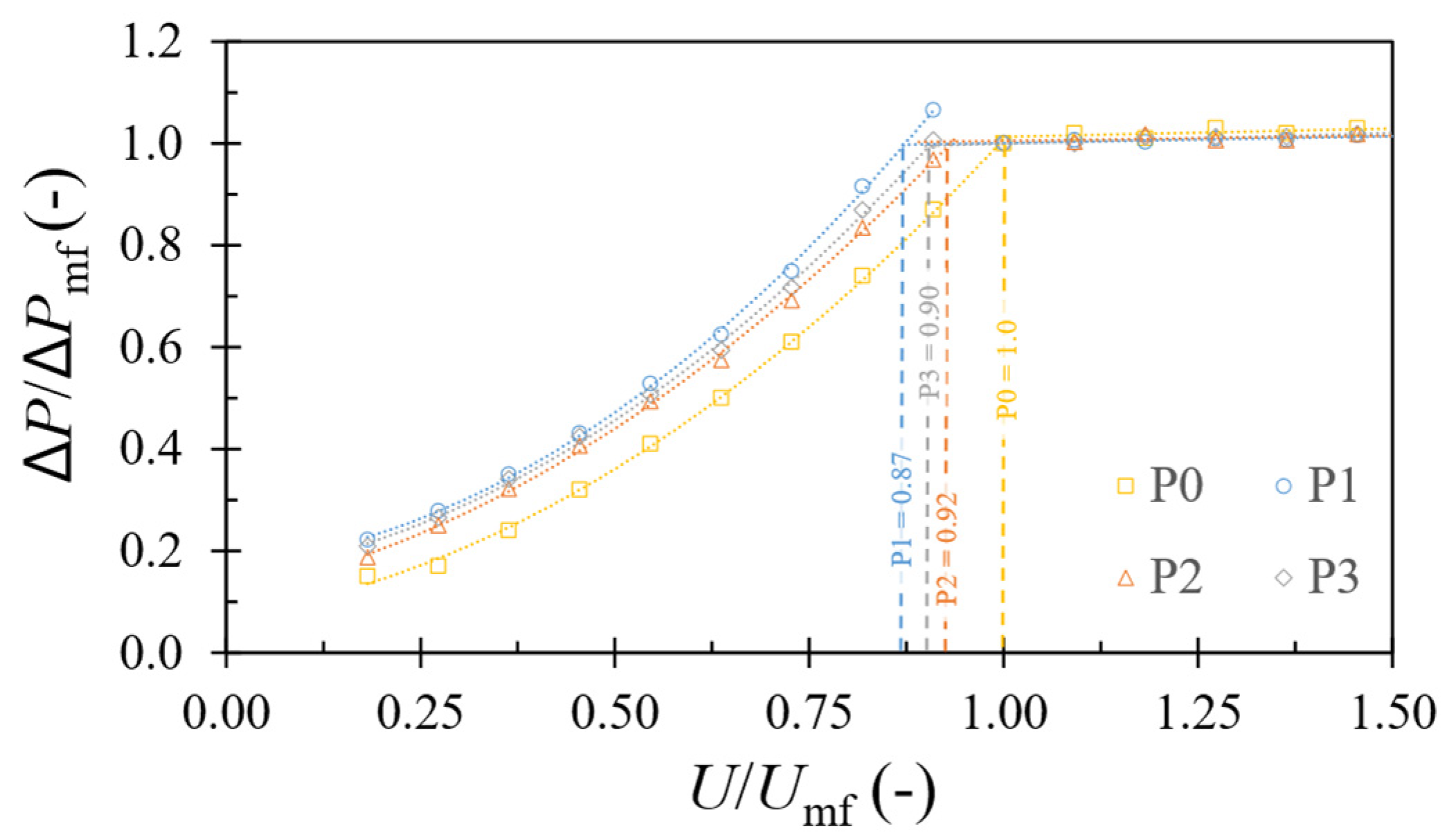
To determine the minimum fluidization velocities in a fluidized bed reactor, the variations in pressure drop from the bed inlet to the freeboard were plotted against the superficial gas velocities using different types of moving internals: no internals (P0), Super Raschig (P1), Pall (P2), and square (P3) rings (Figure 2). These variations were normalized to the minimum fluidization pressure drop of the vertical bed (ΔPmf = 0.308 psig) and the minimum fluidization velocity (Umf = 0.25 m/s) used as a reference for comparison.
Compared with the P0 case, the P1 internals, while having high porosity and the ability to sustain multidirectional microflows, were responsible for an increased pressure drop at velocities below the minimum bed fluidization velocity (Umf-P1 = 0.87Umf-P0) due to the trapping of several bed particles that ballasted the internals and blocked their movement. However, when the bubbling regime was reached, i.e., when the gas velocity was sufficient to form bubbles, the latter could easily pass through the interior of the bed and help to “decongest” the inner space of the internals, which resulted in a pressure drop similar to that of the bed without internals. On the other hand, the P2 internals, although smaller than P1, had a more moderate fixed-bed pressure drop due to their cylindrical shape and fewer open spaces that limited the ingress and egress of particles, thus facilitating the passage of gas around or through them. In the presence of the P1 internals, the minimum bed fluidization was closest to P0 conditions, with a value of 0.92Umf-P0, surpassing all other internals. The P3 internals, with their square configuration and solid walls, severely limited the particle access to their interior space only through the gaps between the internals and the bed walls. The result was a resistance to gas flow that exceeded that of either no internals P0 or P2. However, providing a space sparsely occupied by the bed particles resulted in a lower pressure drop than P1 (Umf-P3 = 0.90Umf-P0).

3.2. Internals and Bubble Coalescence Inhibition

The vertical configuration of the internal-free fluidized bed served as a baseline for comparison with the P1, P2, and P3 modalities. Bubbles within the system were uniquely labeled to better track their trajectory and behavior, as shown in Figure 3. Sequential snapshots that were taken at 70 ms intervals in the internals-free vertical fluidized bed (Figure 3-P0) showed that the larger bubbles exerted an influence on their smaller neighbors, forcing them to undergo both vertical and lateral displacements, culminating in coalescence. During the initial phase, the four identified bubbles followed a zigzag trajectory, which was a result of the attraction exerted by the wake region of the upper bubble in each pair. After 0.14 s, bubbles 1 and 2 merged to form bubble 1+2, and a similar merging occurred with bubbles 3 and 4, resulting in the formation of a larger bubble identified as 3+4. For the next 70 ms, bubble 3+4 accelerated toward the trajectory of bubble 1+2. At t = 0.28 ms, both bubbles merged and ascended to the freeboard, which was collectively identified as bubble 1+2+3+4.
In the case of the P1 internals (Figure 3-P1), a significant reduction in bubble rise velocity was observed compared with the internals-free fluidized bed (Figure 3-P0). Therefore, the snapshot intervals were set to 90 ms in order to track the rise of the labeled bubbles over a longer time lapse of 360 ms (Figure 3-P1). The distinctive hollow structure of P1, which was characterized by its significant internal porosity, facilitated the free circulation of particles within its interior. At the same time, this structure acted as a deterrent, preventing approaching bubbles from coalescing into larger entities, in contrast with the internals-free fluidized bed. Hence, despite the tendency for a cluster of rising bubbles to accrue in proximity, the presence of P1 internals acted as a barrier, preventing them from coalescing and growing into larger bubbles. This was evident in the case of bubbles 1, 2, 3, 5+6, and 4+7+8 at t4. Furthermore, coalescence was not a permanent state, and bubbles could swiftly disintegrate upon collision with other internals, as exemplified by the behavior of bubbles 1 and 2 at t2 and t3.
The floating P2 internals (Figure 3-P2), which were characterized by smaller wall openings than P1, provided more restricted entry/exit for bed particles. This resulted in the formation of a new, more dilute emulsion phase within the internals themselves. This region of least resistance redirected some of the gas flow into the internals at the expense of the bubble and bed emulsion phases. This was especially accentuated when the internals fell over the bubble roof into their gas-rich core, exposing the particles trapped in the falling internals to the high-velocity gas in the core of the bubbles. This exposure increased the efficiency of the gas–solid contact. The exclusive opportunity for tiny bubbles to coalesce lay in their ability to navigate through the spaces between the internals, as illustrated in Figure 3-P2 during the time interval from t0 to t1. This phenomenon was exemplified by the bubbles labeled 7, 8, 4, and 5, which merged into pairs 7+8 and 4+5. Indeed, P2 internals also affected the dissipation rate of bubble wakes in their immediate vicinity. As a result, smaller bubbles (7+8+9 at t3 and t4) that followed larger front bubbles (1+2+3 at t3 and t4) were deprived of the kinetic energy of the frontal bubble’s wake. This prevented larger bubbles from coalescing with their lateral neighbors, allowing them to continue to rise vertically toward the freeboard (Figure 3-P2). Consequently, the coalescence rate of bubbles was primarily influenced by the presence of nearby internals, which restricted larger bubbles from coalescing and allowed only the smaller ones to connect with their counterparts.
By having only two openings and being 1.2 mm smaller than the gap between the front and rear walls, the P3 internals (Figure 3-P3) exhibited a lower pressure drop when empty. This characteristic allowed some of the gas flow that would normally pass through the emulsion phase to be bypassed. However, the EPS particles, each less than 1 mm in size, could be transported by the air within the internals and gradually filled the internals. Once filled, the internals experienced a significant increase in pressure drop, resulting in a noticeable reduction in the gas flow. Gas tended to escape preferentially along the outer walls of the internals. As a result, the driving force for particles to exit the internals was reduced, resulting in the entrapment of particles within the internals for an extended period. P3 internals, which were characterized by walls without openings, were sensitive to the bubble wakes and were pulled toward the wake region. Internals located within the proximity of each bubble’s cloud descended toward the wake region, which is illustrated for t0 to t3 around bubble number 1 and in the proximity of bubbles 2 and 3 at t3 and t4. In addition, the internals located at the top of each bubble descended from within the bubbles to the wake region. This concentration of internals within the wake region induced a notable pressure drop that counteracted the effects of the bubble wake and prevented coalescence. As a result, trailing bubbles maintained their distance (7.1 cm between t0 and t4) from the leading bubble until they reached the freeboard, as depicted in Figure 3-P3.

3.3. Time-Average Local Void Fraction/Velocity Field

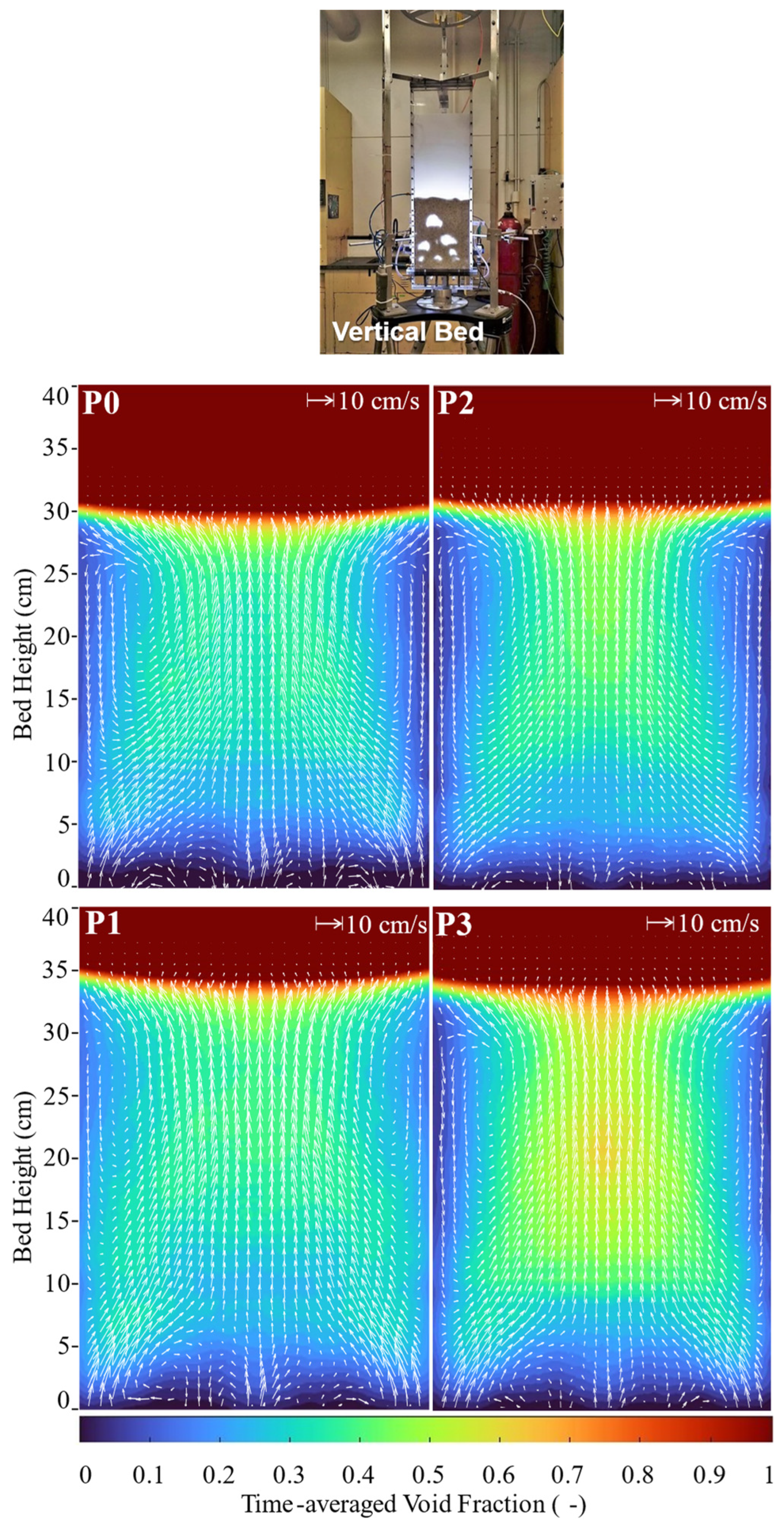
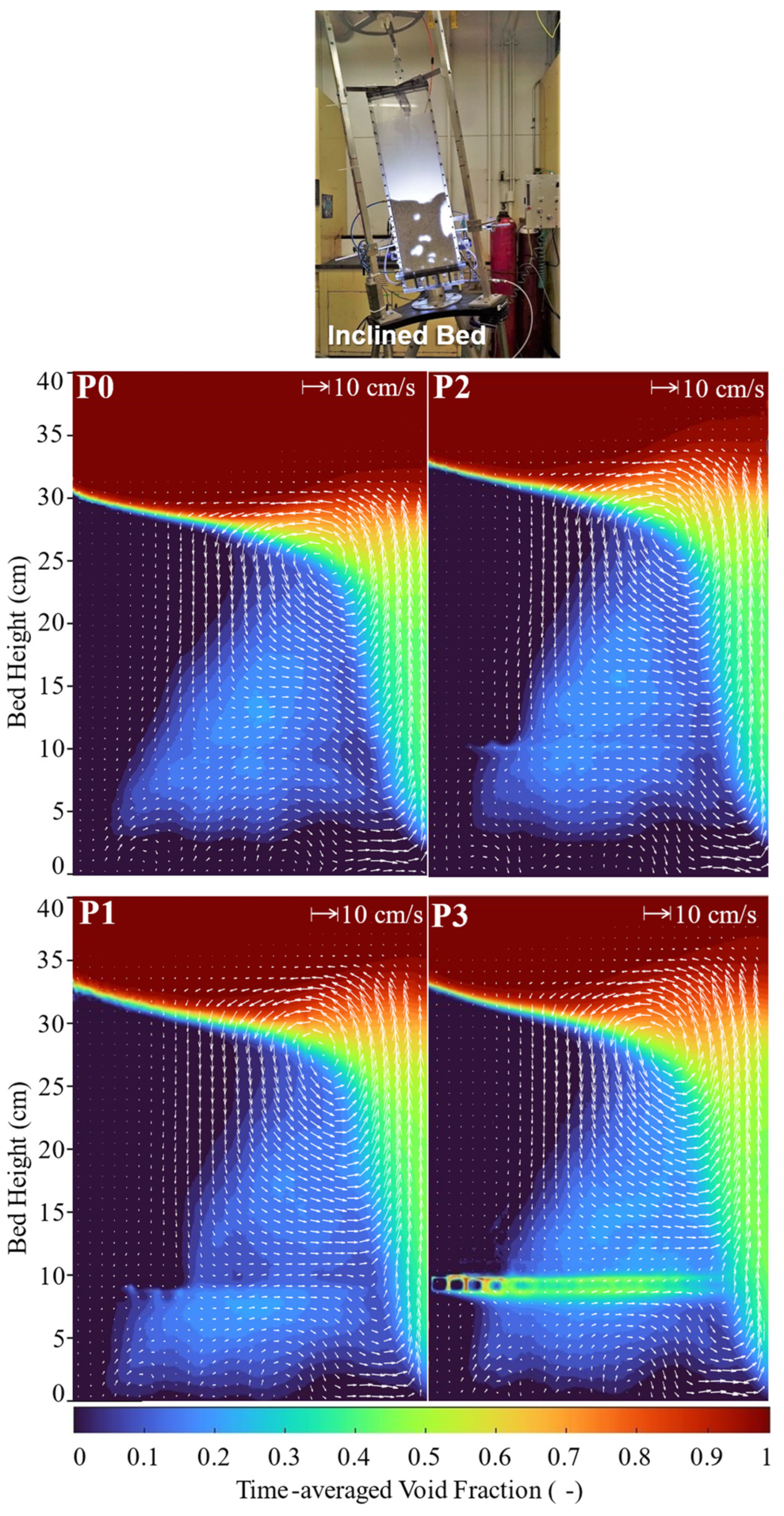
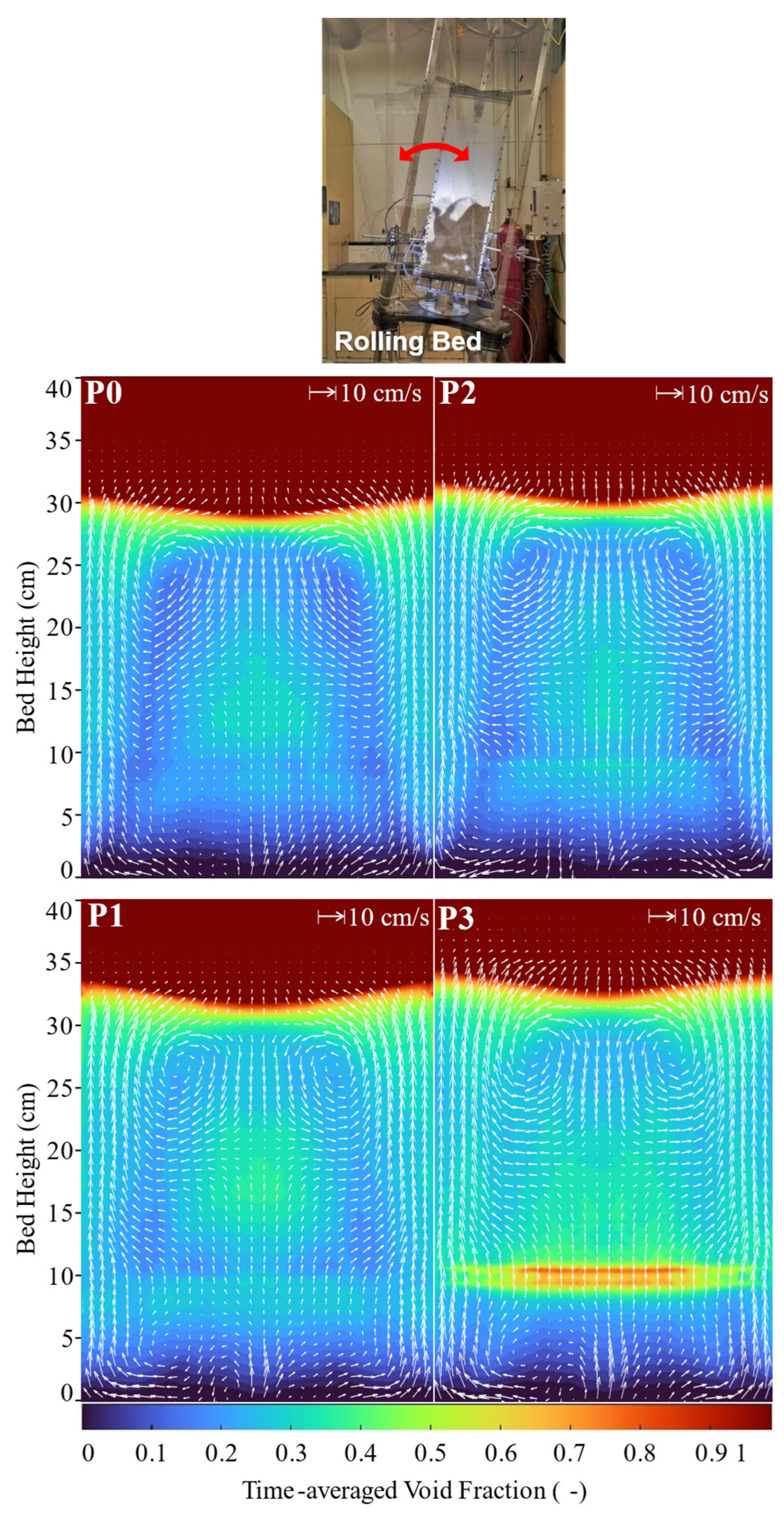
By simultaneously applying digital image analysis (DIA) to assess the local void fraction and particle image velocimetry (PIV) to assess the local particle velocities, and averaging these data over time, a comprehensive picture of the intertwined dynamics of the gas flow and solid phase motion was obtained. This approach was applied to three different bed configurations: vertical, statically inclined (9°), and rolling at a ±9° amplitude and 0.1 Hz frequency. The time-averaged local void fraction and particle velocity fields for these configurations are detailed in Figure 4, Figure 5 and Figure 6.

3.3.1. Vertical Bed

In a vertically oriented fluidized bed with no internals (see Figure 4-P0), the bed height was observed to reach approximately 30 cm during the bubbling regime, which was achieved at a gas superficial velocity of 1.5Umf. This particular configuration served as a baseline for evaluating the effects of different freely mobile internals, specifically P1, P2, and P3.
The introduction of P1 internals resulted in a noticeable increase in bed height, indicating an increase in pressure drop as described above. This outcome was attributed to the distinctive open geometry of the P1 packing, fostering a form of “extrusion” that generated smaller and more evenly distributed bubbles. These smaller bubbles, with correspondingly weaker wakes, exerted minimal influence on the displacement of the P1 internals. The hollow design of the P1 internals promoted gas and particle movement, dampening the disruptive bubble wake force and ensuring stable positioning of the internals. In addition, the ability of the P1 internals to split larger bubbles improved the uniformity of bubble distribution throughout the bed, as shown in the contour plot (Figure 4-P1). A comparison of Figure 4-P0 and Figure 4-P1 shows a significant improvement in the time-averaged void fraction near the walls, which increased from 5% without internals to 25% with P1 internals.
Similar to the P1 internals, the arrangement of the Pall rings in the fluidized bed influenced their interaction with bubbles and, consequently, their displacement (Figure 4-P2). However, in the case of P2 internals, the trajectories of bubbles closely resembled those in the internal-free bed (Figure 4-P0), maintaining a comparable time-averaged void fraction near the walls of approximately 5%. Additionally, the introduction of P2 internals altered the particle flow dynamics, leading to an extended residence time for bubbles within the bed. This modification further contributed to an elevated pressure drop, resulting in a roughly 3% increase in bed height. This was particularly evident in the yellow-green area of Figure 4-P2, which shows a significant increase in the bubble residence time in the top third of the bed compared with the Figure 4-P0 condition, with the time-averaged void fraction increasing from 35% to 55%. Despite these changes, the particle trajectories in the P2 condition were very similar to those in the P0 scenario. However, there was an observable increase in the upward velocity in the center of the bed, highlighting the pronounced influence of the P2 internals on the bed dynamics.
The incorporation of P3 internals into the fluidized bed hindered the bubble coalescence (Section 3.2) by inducing temporary overcrowding after each bubble ascended, which led to an additional pressure drop in the bubble wake region and consequently amplified the drag force on the bubbles. This increased drag extended the bubble residence time, culminating in an increased bed height of 34 cm (Figure 4-P2), which was a 13% increase over the P0 condition (Figure 4-P0). In addition, the increased drag force exerted by the P3 internals directed bubbles toward the center of the bed. This rerouting nearly doubled the time-averaged void fraction in the center of the bed to 68% and slightly depleted the presence of bubbles near the walls to 2%, significantly altering the distribution of bubbles within the bed. Despite these changes, the P3 internals did not facilitate the formation of smaller bubbles. The particle and bubble phase trajectories closely resembled those of a vertical bed without internals, maintaining a core–annulus structure, as shown in Figure 4-P3.

3.3.2. Inclined Bed

Operating the fluidized bed at a 9-degree tilt resulted in a transition from a bubbling regime to a sidewall slug flow regime. In this configuration, most of the gas flow was concentrated in the slug regions, leaving areas outside of these zones with significantly reduced gas flow. As a result, the internals located in these low-flow regions remained predominantly stationary and less effective. The reduced gas flow outside the slug zones resulted in minor vibration and particle displacement, causing the internals to settle on a wire located 8 cm above the distributor, which was originally designed as a settling inhibitor. Crowding the internals on this wire had a profound effect on the bed dynamics, particularly by increasing the pressure drop near the wire and trapping bubbles beneath the layer of internals. This arrangement allowed the internals to act as a secondary distributor, as illustrated in Figure 5-P1–P3. Furthermore, the introduction of different types of internals in this inclined arrangement led to a variable increase in the bed height, with P1 causing the most significant increase, followed by P3 and P2. This variation underscores the distinct influence of each type of internal on the bed dynamics in an inclined setting. In addition, the presence of the internals slightly reduced the size of the wall slug region, highlighting their influence on gas flow distribution and bubble dynamics within the bed.

3.3.3. Rolling Bed

The behavior of the fluidized bed was studied under a rolling motion with an amplitude of 9 degrees and a frequency of 0.1 Hz, operating at 1.5Umf. The study included four different conditions: P0 (no internals), P1 (Super Raschig ring), P2 (Pall ring), and P3 (square ring). In the P0 condition (Figure 6-P0), the homogeneity of the bed was compromised by the formation of transient wall slugs at the specified amplitude. The introduction of P1 internals resulted in a 10% increase in the average bed holdup (Figure 6-P1), while P2 internals had a modest effect, contributing to a 3% increase in bed expansion (Figure 6-P2). In the P3 scenario, the addition of square ring internals had a significant effect on the bed hold-up, increasing it by approximately 15% (Figure 6-P3). Corresponding to these alterations were notable shifts in the fluid dynamics within the bed. The initial counterclockwise core–annulus gulf stream near the freeboard (Figure 6-P0) became less pronounced, and a crisscrossing particle trajectory emerged beneath it (Figure 6-P1, P2, P3), indicating increased local mixing in the lower half of the bed. This shift in flow dynamics, coupled with variations in the time-averaged void fraction—30% for P0, approximately 11% for P1, 15% for P2, and a reduced 5% for P3—underscores the significant impact of moving internals in improving the uniformity of bubble distribution in the fluidized bed.

3.4. Velocity Components of Granular Phase

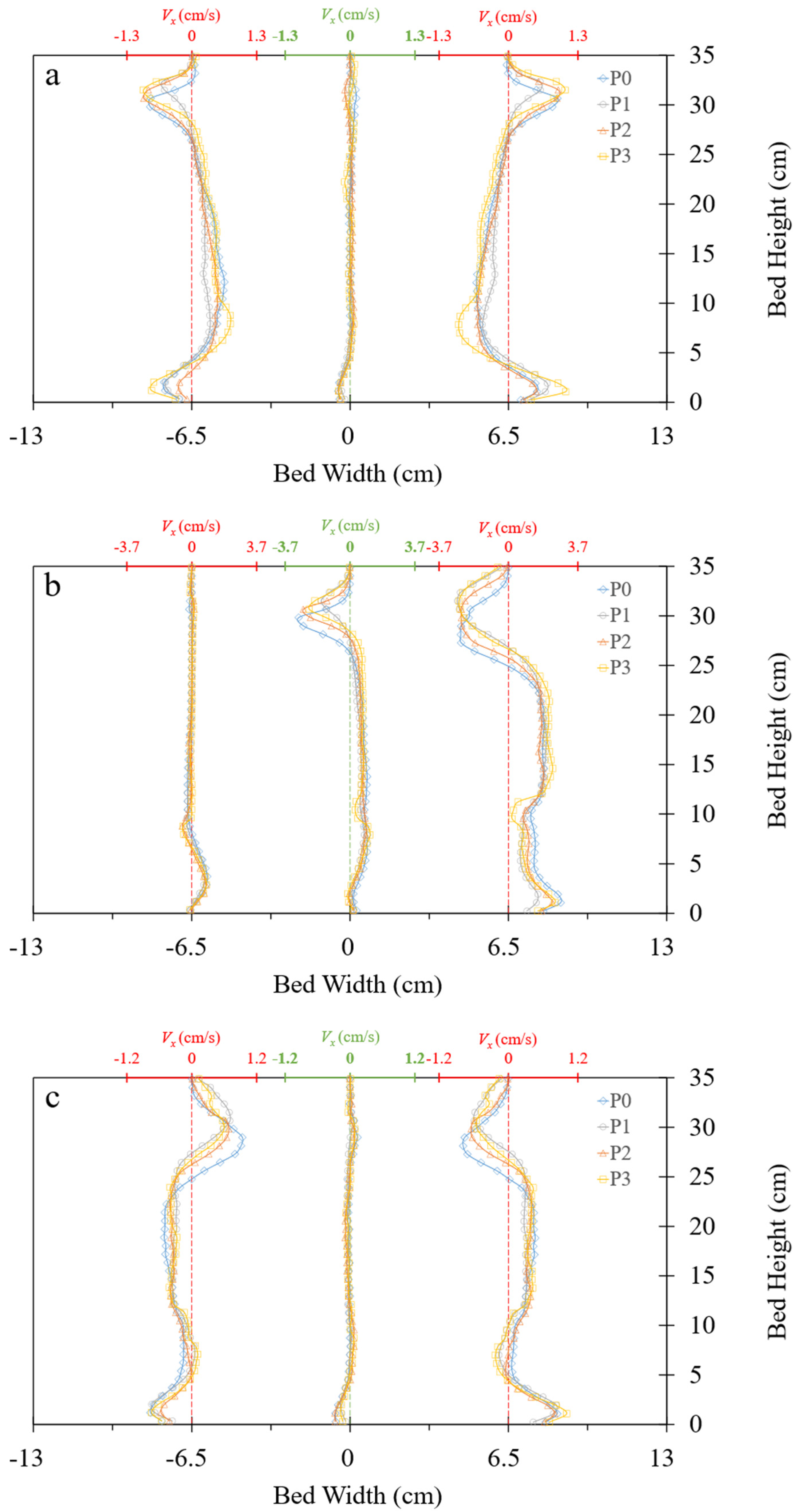
The aim of this section was to provide a thorough quantitative description of the effects on particle velocities induced by different moving internals within the bed under three different conditions: vertical, statically inclined at 9 degrees, and subjected to rolling with an amplitude of 9 degrees at a frequency of 0.1 Hz. To achieve this, quantitative analyses were performed on the Eulerian longitudinal (Figure 7) and transverse (Figure 8) velocity components of particles at different heights and transverse positions within a fluidized bed.
Figure 7a shows that at 8 cm above the distributor, the particle velocities were minimally affected by the internals. However, at the bed’s mid-height (16 cm above the distributor), the P1 internals distinctly decelerated the particle movement compared with the other packings and the P0 case. Conversely, the P2 and P3 internals contributed to the creation of a channel for rapidly ascending particles, with the P3 condition exhibiting the highest velocity. The introduction of internals in both statically inclined and rolling beds resulted in a decrease in the time-averaged ascending particle velocity compared with the P0 condition. The effects of the internals, in descending order, were as follows: P1, P3, and P2, as shown in Figure 7b,c.
In the vertical bed configuration, excluding the entry and exit (freeboard) zones, the longitudinal profiles of the time-averaged transverse particle velocities at the right/left central halves of the bed (±6.5 cm from the bed centerline) closely matched those at the central inversion line, where the VX component reversed its sign (Figure 8a). In this context, it was concluded that the bubbles completed their ascent by erupting in the central region, inducing an outwardly symmetric particle flow from the center to the sidewalls of the bed. The migration of bubbles toward the walls intensified with increasing bed inclination, as shown in Figure 8a. The internals had a marginal effect on the transverse particle velocity, except in the near freeboard region, where the P1 internals reduced the velocity due to increased bed expansion. A similar pattern was observed under inclined conditions, where the internals shifted the core of the counterclockwise particle gulfstream upward, correlating with differences in the hold-up ratio (Figure 8b). In addition, under rolling conditions, the presence of internals could reduce the time-averaged transverse velocity near the freeboard by up to 15%, with P1 internals having the most pronounced effect (see Figure 8c).

4. Conclusions

The primary motivation for this study was to test dynamic tools to mitigate gas maldistribution in a bubbling fluidized bed when subjected to oscillatory vagaries at sea. To this end, various moving internals were evaluated for vertical, inclined, and rolling fluidized bed operation. The observation of bubble and granular phase motion was enabled by combining digital image analysis (DIA) and particle image velocimetry (PIV) to measure local void fractions and time-averaged particle velocities.
Among the three types of packing used as moving internals, the Super Raschig (P1) showed clear superiority over the Pall (P2) and square (P3) rings in all configurations tested:
  • Vertical bed: The introduction of P1 internals had a significantly increased bed height and improved bubble distribution efficiency. This was in contrast with the moderate changes caused by P2 and the less efficient changes caused by P3 internals, highlighting the increased operability of P1 due to its unique geometry that favored the maintenance of smaller bubble sizes.
  • Inclined bed (9°): In this case, the P1 internals were found to be superior to the other internals. Nevertheless, the drastic maldistribution conditions imposed by a static bed inclination could not be corrected by adding internals to the bed.
  • Rolling bed: Once again, the effectiveness of the P1 internals was evident, with a notable 10% increase in the bed void rate due to the presence of smaller bubbles and the inhibition of bubble coalescence, surpassing the improvements achieved by the P2 and P3 internals. This underscores the versatility of the P1 internals in the dynamic environment of rolling fluidized beds.
The effect of these internals on the pressure drop and coalescence prevention in fluidized beds was also investigated. P1 internals, which were characterized by significant porosity, facilitated gas flow, resulting in an efficient reduction of bubble coalescence. Conversely, the P2 internals promoted particle mixing and influenced bubble formation with their smaller openings, while the P3 internals introduced a distinct dynamic that hindered coalescence by modifying the gas flow and particle entrapment patterns.
The study results underscore the superior performance of P1 internals in improving fluidized bed operations, especially under moving vessel operating conditions. This makes them the preferred choice for offshore applications seeking increased efficiency and controlled processing in fluidized bed systems. The significance of these findings extends to providing a fundamental understanding of the continued development of fluidized bed technology in marine applications.

Author Contributions

Conceptualization, A.A.S. and F.L.; methodology, A.A.S.; software, A.A.S.; validation, A.A.S., F.L. and S.M.T.; formal analysis, A.A.S.; investigation, A.A.S.; resources, F.L.; data curation, A.A.S.; writing—original draft preparation, A.A.S.; writing—review and editing, F.L. and S.M.T.; visualization, A.A.S.; supervision, F.L.; project administration, A.A.S.; funding acquisition, F.L. All authors have read and agreed to the published version of the manuscript.

Funding

This research was funded by the Natural Sciences and Engineering Research Council of Canada (NSERC) Discovery grants, the Canada Foundation for Innovation, and the CIRCUIT program for their financial support, and the APC was funded by NSERC.

Institutional Review Board Statement

Not applicable.

Informed Consent Statement

Not applicable.

Data Availability Statement

The original contributions presented in the study are included in the article; further inquiries can be directed to the corresponding author.

Acknowledgments

The authors would like to thank Jérôme Noël for his role in the construction of the setup and his contribution of a 3D sketch of the hexapod assembly.

Conflicts of Interest

The authors declare no conflicts of interest.

Nomenclature

dpParticle diameter (cm)
FIIn-plane missing particles
FOOut-of-plane missing particles
FTParticle shape
ftTracer fraction factor
FΔVelocity distribution
MPixel-to-millimeter conversion factor (mm−1)
NTotal number of particles
NIParticle count in interrogation window
P0No internal
P1Super Raschig ring
P2Pall ring
P3Square ring
RDParticle displacement (m)
UmfMinimum fluidization gas velocity (cm/s)
VXParticle transverse velocity component (cm/s)
VYParticle longitudinal velocity component (cm/s)
ΔPBed pressure drop (psi)
ΔPmfMinimum fluidization pressure drop (psi)
Acronyms
2DTwo dimensional
DIADigital image analysis
ECAEmission control area
EGCSExhaust gas cleaning system
EPSExpandable polystyrene
IMOInternational Maritime Organization
MARPOLInternational Convention for the Prevention of Pollution from Ships
PIVParticle image velocimetry

References

  1. Eyring, V.; Isaksen, I.S.A.; Berntsen, T.; Collins, W.J.; Corbett, J.J.; Endresen, O.; Grainger, R.G.; Moldanova, J.; Schlager, H.; Stevenson, D.S. Transport impacts on atmosphere and climate: Shipping. Atmos. Environ. 2010, 44, 4735–4771. [Google Scholar] [CrossRef]
  2. Motamed Dashliborun, A.; Zhang, J.; Taghavi, S.M.; Larachi, F. 110th anniversary: Marinization of multiphase reactors through the prism of chemical Engineers. Ind. Eng. Chem. Res. 2019, 58, 2607–2630. [Google Scholar] [CrossRef]
  3. Sarbanha, A.-A.; Larachi, F.C.A.; Taghavi, S.-M.; Thiboutot-Rioux, M.; Boudreau, A.; Dugas, G. Mitigation of Ship Emissions: Overview of Recent Trends. Ind. Eng. Chem. Res. 2023, 62, 1707–1724. [Google Scholar] [CrossRef]
  4. Fitzmaurice, M.; Borg, S.; Attard, F.G.; Vella de Fremeaux, P.M. Research Handbook on Ocean Governance Law. In Chapter 6: The International Convention for the Prevention of Pollution from Ships (MARPOL); Edward Elgar Publishing: Northampton, MA, USA, 2023; pp. 91–108. [Google Scholar]
  5. Zannis, T.C.; Katsanis, J.S.; Christopoulos, G.P.; Yfantis, E.A.; Papagiannakis, R.G.; Pariotis, E.G.; Rakopoulos, D.C.; Rakopoulos, C.D.; Vallis, A.G. Marine Exhaust Gas Treatment Systems for Compliance with the IMO 2020 Global Sulfur Cap and Tier III NOx Limits: A Review. Energies 2022, 15, 3638. [Google Scholar] [CrossRef]
  6. Papadopoulos, C.; Kourtelesis, M.; Moschovi, A.M.; Sakkas, K.M.; Yakoumis, I. Selected Techniques for Cutting SOx Emissions in Maritime Industry. Technologies 2022, 10, 99. [Google Scholar] [CrossRef]
  7. Joung, T.-H.; Kang, S.-G.; Lee, J.-K.; Ahn, J. The IMO initial strategy for reducing Greenhouse Gas(GHG) emissions, and its follow-up actions towards 2050. J. Int. Marit. Saf. Environ. Aff. Ship. 2020, 4, 1–7. [Google Scholar] [CrossRef]
  8. Chong, Y.O.; Leung, L.S.; Nguyen, T.H.; Teo, C.S. Inclined Fluidized Bed, AIChE Symposium Series; Department of Chemical Engineering, University of Queensland: St. Lucia, Australia, 1984; p. 241. [Google Scholar]
  9. O’dea, D.; Rudolph, V.; Chong, Y.; Leung, L. The effect of inclination on fluidized beds. Powder Technol. 1990, 63, 169–178. [Google Scholar] [CrossRef]
  10. Liang, J.D.; Hsu, C.Y.; Hung, T.C.; Chiang, Y.C.; Chen, S.L. Geometrical parameters analysis of improved circulating inclined fluidized beds for general HVAC duct systems. Appl. Energy 2018, 230, 784–793. [Google Scholar] [CrossRef]
  11. Chiang, Y.C.; Chen, C.H.; Chiang, Y.C.; Chen, S.L. Circulating inclined fluidized beds with application for desiccant dehumidification systems. Appl. Energy 2016, 175, 199–211. [Google Scholar] [CrossRef]
  12. Yasui, T.; Nakayama, T.; Yoshida, K. Heat-transfer characteristics in a rocking fluidized bed. Int. Commun. Heat Mass Transf. 1984, 11, 477–488. [Google Scholar] [CrossRef]
  13. Mutsers, S.M.P.; Rietema, K. The effect of interparticle forces on the expansion of a homogeneous gas-fluidized bed. Powder Technol. 1977, 18, 239–248. [Google Scholar] [CrossRef]
  14. Gilbertson, M.A.; Yates, J.G. The tilting fluidized bed: A re-examination. Powder Technol. 1996, 89, 26–36. [Google Scholar] [CrossRef]
  15. Hamahira, S.M.Y.; Yutani, S.; Hashimoto, Y. Experimental Research of Fluidized Bed Combustion for Marine Application. J. Mar. Eng. Soc. Jpn. 1984, 18, 856–866. [Google Scholar] [CrossRef]
  16. Murata, H.; Oka, H.; Adachi, M.; Harumi, K. Effects of the ship motion on gas–solid flow and heat transfer in a circulating fluidized bed. Powder Technol. 2012, 231, 7–17. [Google Scholar] [CrossRef]
  17. Sarbanha, A.A.; Larachi, F.; Taghavi, S.M. Bubble and particle dynamics in a thin rectangular bubbling fluidized bed under emulated marine instabilities. Chem. Eng. Sci. 2023, 280, 119041. [Google Scholar] [CrossRef]
  18. Sarbanha, A.A.; Larachi, F.; Taghavi, S.M. Solids Mixing in Marinized Bubbling Fluidized Beds: Gas Distribution Study. Ind. Eng. Chem. Res. 2023, 62, 18879–18891. [Google Scholar] [CrossRef]
  19. Zhao, T.; Ding, X.; Wang, Z.; Zhang, Y.; Liu, K. Dynamic control method of particle distribution uniformity in the rolling circulating fluidized bed (RCFB). Eng. Appl. Comput. Fluid Mech. 2021, 15, 210–221. [Google Scholar] [CrossRef]
  20. Wang, Z.; Zhao, T.; Yao, J.; Liu, K.; Takei, M. Influence of particle size on the exit effect of a full-scale rolling circulating fluidized bed. Partic. Sci. Technol. 2018, 36, 541–551. [Google Scholar] [CrossRef]
  21. Zhao, T.; Nakamura, Y.; Liu, K.; Murata, H.; Takei, M. The effect of rolling amplitude and period on particle distribution behavior in a rolling circulating fluidized bed. Powder Technol. 2016, 294, 484–492. [Google Scholar] [CrossRef]
  22. Fu, Z.; Zhu, J. Characterization of the Effective Density for the Separation of Immersed Objects in the Gas–Solid Fluidized Bed Coal Beneficiator. Ind. Eng. Chem. Res. 2023, 62, 17236–17242. [Google Scholar] [CrossRef]
  23. Utomo, M.S.K.T.S.; Yohana, I.E.; Krisna, B.; Dwinanda, M.F.; Tauviqirrahman, M.; Choi, K.-H. Effect of ring baffle on erosion in circulating fluidized bed boiler. Cogent Eng. 2023, 10, 2274534. [Google Scholar] [CrossRef]
  24. Huang, Y.; Bao, X.; Duan, Y.; Li, L.; Fang, D.; Wang, Y.; Duan, L. Heat transfer behavior of an immersed tube with sCO2 working fluid in a hot fluidized bed at high pressure. Fuel 2023, 333, 126457. [Google Scholar] [CrossRef]
  25. Nemati, N.; Filiu Moreno, P.; Rydén, M. Investigation of the hydrodynamics of packed-fluidized beds: Characterization of solids flux. Fuel 2023, 335, 127010. [Google Scholar] [CrossRef]
  26. Bouhamri, N.; Zelmat, M.E.; Tilmatine, A. Micronized plastic waste recycling using two-disc tribo-electrostatic separation process. Adv. Powder Technol. 2019, 30, 625–631. [Google Scholar] [CrossRef]
  27. Uemoto, K.; Narita, S.; Harada, S.; Sakamoto, Y.; Tsuji, T.; Oshitani, J.; Kajiwara, H.; Matsuoka, K. Wireless measurement of Float-Sink motion of Variously-shaped objects in Gas-Solid fluidized bed. Adv. Powder Technol. 2023, 34, 104111. [Google Scholar] [CrossRef]
  28. Gallucci, F. 4-Fluidized bed membrane reactors. In Current Trends and Future Developments on (Bio)Membranes; Basile, A., Gallucci, F., Eds.; Elsevier: Amsterdam, The Netherlands, 2023; pp. 77–93. [Google Scholar]
  29. Liu, W.; Larachi, F.; Chu, G.-W.; Luo, Y.; Taghavi, S.M. Spreading of point-source liquid spills in a thin rectangular packed bed under simulated marine conditions. AIChE J. 2023, 69, e17424. [Google Scholar] [CrossRef]
  30. Grace, J.R.; Bi, X.; Ellis, N. Essentials of Fluidization Technology; John Wiley & Sons: Hoboken, NJ, USA, 2020. [Google Scholar]
  31. Antistatic Agent for Expanded Polystyrene (EPS) and Expanded Polypropylene (EPP) (MECOSTAT®-3/549); MEK GmbH: Allensbach, Germany, 2022.
  32. Xiao, D.; Dong, X.; Hu, S.; Liu, X. Coupling particle image velocimetry and digital image analysis to characterize cluster dynamics in a fast fluidized bed. Powder Technol. 2024, 434, 119267. [Google Scholar] [CrossRef]
  33. Yuan, Z.; Huang, Z.; Ma, S.; Zhao, G.; Yang, H.; Yue, G. Experimental investigation on the effect of superficial gas velocity on bubble dynamics properties of B particles in gas–solid fluidized bed reactor using digital image analysis technique. Fuel 2023, 348, 128617. [Google Scholar] [CrossRef]
  34. Zhu, X.; Liu, Y.; Li, Y.; Wang, H.; Wang, Z. Bubble behaviors of geldart B particle in a pseudo two-dimensional pressurized fluidized bed. Particuology 2023, 79, 121–132. [Google Scholar] [CrossRef]
  35. Hou, J.; Grace, J.R.; Bi, X. Effect of gas properties on particle charging and wall fouling in gas-solids fluidized beds. Powder Technol. 2023, 421, 118419. [Google Scholar] [CrossRef]
  36. Westerweel, J. Fundamentals of digital particle image velocimetry. Meas. Sci. Technol. 1997, 8, 1379–1392. [Google Scholar] [CrossRef]
  37. Sarbanha, A.A.; Movahedirad, S.; Ehsani, M. On the hydrodynamics of a pseudo two-dimensional two-zone gas-solid fluidized bed. Chem. Eng. J. 2018, 350, 971–981. [Google Scholar] [CrossRef]
  38. Jahandar Lashaki, M.; Sarbanha, A.A.; Movahedirad, S. Overall particles flow pattern in a two-zone gas-solid fluidized bed with a secondary-gas stream. Chem. Eng. Res. Des. 2022, 187, 570–583. [Google Scholar] [CrossRef]
  39. Helmi, A.; Campos Velarde, I.; Gallucci, F.; van Sint Annaland, M. Hydrodynamics of dense gas-solid fluidized beds with immersed vertical membranes using an endoscopic-laser PIV/DIA technique. Chem. Eng. Sci. 2018, 182, 146–161. [Google Scholar] [CrossRef]
  40. Campos Velarde, I.; Gallucci, F.; van Sint Annaland, M. Development of an endoscopic-laser PIV/DIA technique for high-temperaturegas–solid fluidized beds. Chem. Eng. Sci. 2016, 143, 351–363. [Google Scholar] [CrossRef]
  41. Carlos Varas, A.E.; Peters, E.A.J.F.; Kuipers, J.A.M. Experimental study of fullfield riser hydrodynamics by PIV/DIA coupling. Powder Technol. 2017, 313, 402–416. [Google Scholar] [CrossRef]
  42. Julián, I.; Gallucci, F.; Van Sint Annaland, M.; Herguido, J.; Menéndez, M. Hydrodynamic study of a Two-Section Two-Zone Fluidized Bed Reactor with an immersed tube bank via PIV/DIA. Chem. Eng. Sci. 2015, 134, 238–250. [Google Scholar] [CrossRef]
  43. Julián, A.I.; Gallucci, F.; van Sint Annaland, M.; Herguido, J.; Menéndez, M. Coupled PIV/DIA for fluid dynamics studies on a Two-Section Two-Zone Fluidized Bed Reactor. Chem. Eng. J. 2012, 207–208, 122–132. [Google Scholar] [CrossRef]
  44. Roghair, I. Development of an Experimental Method to Investigate the Hydrodynamics in a Fluidized Bed Using PIV and DIA; University of Twente: Enschede, The Netherlands, 2007. [Google Scholar]
  45. Sugii, Y.; Nishio, S.; Okuno, T.; Okamoto, K. A highly accurate iterative PIV technique using a gradient method. Meas. Sci. Technol. 2000, 11, 1666–1673. [Google Scholar] [CrossRef]
  46. Adrian, R. Dynamic ranges of velocity and spatial resolution of particle image velocimetry. Meas. Sci. Technol. 1997, 8, 1393–1398. [Google Scholar] [CrossRef]
  47. Keane, R.; Adrian, R. Optimization of particle image velocimeters: II. Multiple pulsed systems. Meas. Sci. Technol. 1991, 2, 963–974. [Google Scholar] [CrossRef]
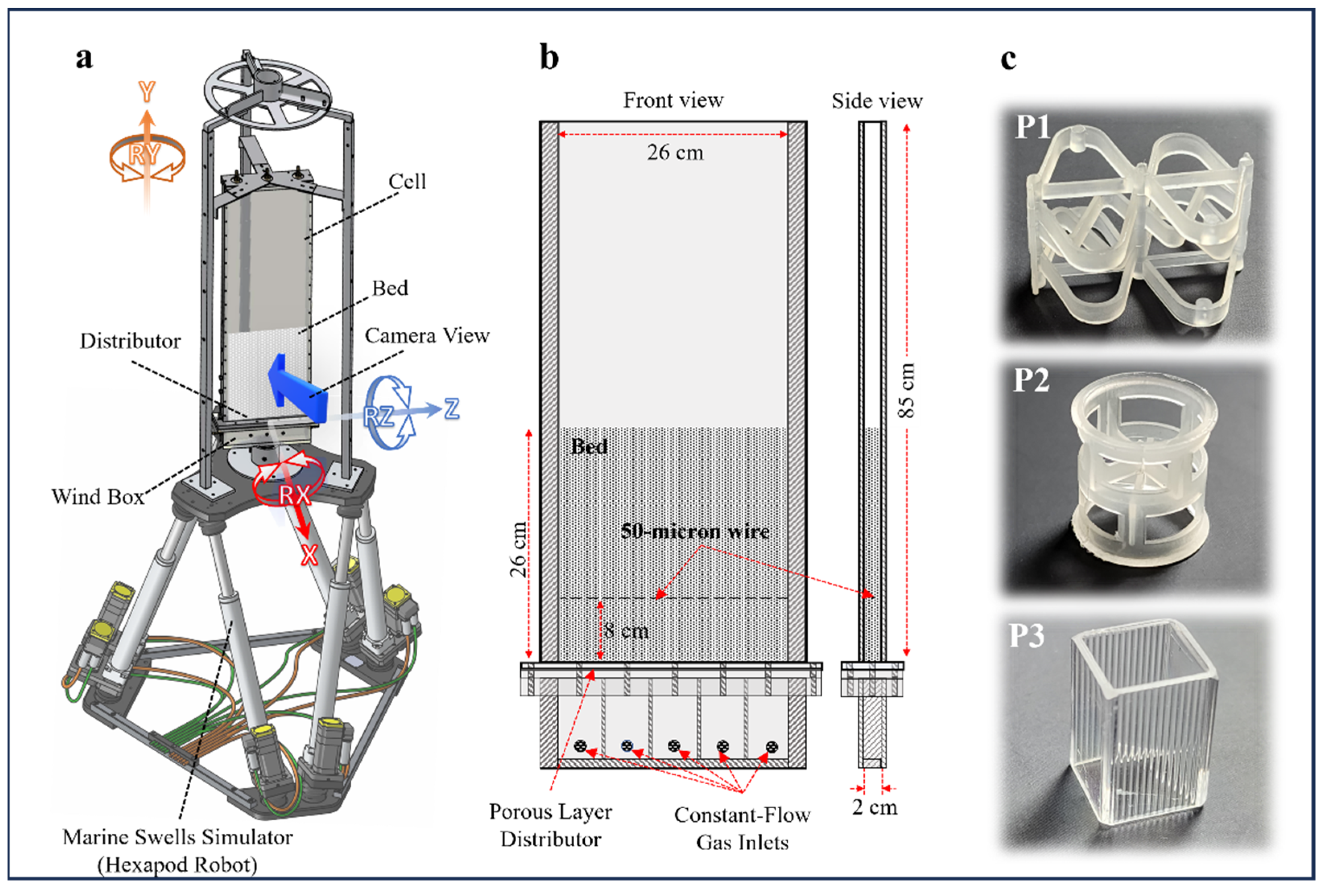
Figure 1. Schematic showing the cell position on a hexapod robot, along with its coordinate system (a); detailed view of the 2D parallelepipedal enclosure (b); and various internal components: P1—Super Raschig ring, P2—Pall ring, and P3—square ring (c).
Energies 17 00672 g001
Figure 2. Pressure drop vs. superficial velocity for vertical bed with various internals (P0: no internals, P1: Super Raschig, P2: Pall ring, P3: square ring).
Energies 17 00672 g002
Figure 3. Depiction of bubble behavior and trajectory (red arrows) in momentary snapshots illustrating a bed without internals (P0), and those with Super Raschig (P1), Pall (P2), and square (P3) rings in upright fluidized beds and U/Umf = 1.5.
Energies 17 00672 g003
Figure 4. Contour plots of the time-averaged void fraction from DIA, alongside the time-averaged velocity field from PIV in an upright fluidized bed with P0 to P3 internal configurations at U/Umf = 1.5.
Energies 17 00672 g004
Figure 5. Contour plots of the time-averaged void fraction using DIA, paired with the time-averaged velocity data from PIV in a fluidized bed inclined at 9° featuring P0 to P3 internal setups at U/Umf = 1.5.
Energies 17 00672 g005
Figure 6. Contour plots of the time-averaged void fraction derived from DIA, combined with the time-averaged velocity data from PIV in a fluidized bed rolling at 9° and 0.1 Hz incorporating P0 to P3 internal setups at U/Umf = 1.5.
Energies 17 00672 g006
Figure 7. Time-averaged cross-sectional profiles of solids’ axial speeds at three heights in vertical (a), 9° inclined (b), and (9°, 0.1 Hz) rolling (c) fluidized beds, with P0 to P3 internal modalities at U/Umf = 1.5.
Energies 17 00672 g007
Figure 8. Time-averaged cross-sectional profiles of solids’ transversal velocity at three different widths in straight (a), 9° inclined (b), and (9°, 0.1 Hz) rolling (c) fluidized beds, with P0 to P3 internal modalities at U/Umf = 1.5.
Energies 17 00672 g008
Disclaimer/Publisher’s Note: The statements, opinions and data contained in all publications are solely those of the individual author(s) and contributor(s) and not of MDPI and/or the editor(s). MDPI and/or the editor(s) disclaim responsibility for any injury to people or property resulting from any ideas, methods, instructions or products referred to in the content.