1. Introduction
Microgrid structures are designed to facilitate the grid integration of renewable energy sources, such as PV systems, wind turbines, and energy storage systems [
1]. Numerous studies focus on DC microgrids, primarily due to their ease of control, the absence of requirements for frequency and reactive power control, and the compatibility of renewable energy sources and energy storage systems with DC structures [
2,
3]. Control strategies play a crucial role in microgrid studies, employing various methods such as central, decentralized, hierarchical, and distributed hierarchical approaches [
4].
Central control has emerged as the simplest and most efficient method, as the microgrid is centrally managed [
5]. However, its reliance on a central controller makes the entire system vulnerable to collapse in case of a malfunction [
5]. Additionally, the effectiveness of central control diminishes with increased distances between sources. Decentralized control, involving local source control without communication, proves effective for power sharing but falls short in maintaining voltage stability and adapting to changing microgrid conditions [
6]. The hierarchical control method combines the advantages of central and decentralized mechanisms, with different control levels operating at distinct times. While primary control functions locally, secondary and tertiary control operate centrally [
7]. Though less dependent on communication than central control, this method is still susceptible to stability disruptions caused by communication delays, especially with increased source distances [
3].
In contrast to hierarchical control, the distributed method operates all control levels locally without a central controller, offering a decentralized approach to microgrid control [
8].
The distributed hierarchical control method has been widely used to control microgrids in recent years [
9,
10] due to its advantages such as minimizing the communication network cost [
11], reducing the communication burden, and being resistant to communication errors [
12,
13]. This hierarchical structure involves multiple control levels operating at different time intervals [
9,
10]. The primary controller, situated at the lowest level, operates locally and does not require communication. Typically implemented using droop control, this method regulates power sharing between sources [
14]. While primary control facilitates power sharing, it tends to compromise voltage stability [
15]. Voltage-stability issues resulting from primary control are rectified at higher hierarchical levels [
16]. The upper levels consist of secondary and tertiary control. While secondary control is sufficient to ensure energy quality in island microgrids [
11], tertiary control is utilized to manage power flow in systems where microgrids are connected to the grid or other microgrids [
17]. Additionally, these upper control levels exchange data with other controllers through the distributed communication network [
18]. The communication burden is reduced, and the communication distance is shortened because the microgrid is not controlled from a single center and has a distributed network structure [
19]. In this control method, various approaches are employed to estimate the data of the entire system by exchanging information solely with designated controllers [
20]. Consensus-based distributed control algorithms are the most common methods used to estimate the necessary energy parameters of the entire system with data received from neighbors [
21,
22]. By receiving data only from specified controllers, these algorithms offer comprehensive information about the entire system [
23].
While traditional distributed hierarchical control effectively manages microgrids with constant power sources, it may prove inadequate for those incorporating renewable energy sources such as PV systems and wind turbines and energy storage systems such as batteries [
24]. To ensure the energy quality of microgrids, energy flow must be regulated according to the dynamic power states of PV systems and wind turbines and the state of charge of batteries [
25]. Distributed hierarchical control algorithms have been developed for microgrids with these sources, incorporating additional energy-management algorithms [
26,
27].
In support of the frequency stability of microgrids with PV sources, an event-triggered distributed hierarchical control was developed in the study reported in [
24]. This controller enables PV systems to contribute to frequency stability, reducing the reliance on energy reserves from traditional synchronous generators or energy storage systems. Another study, referenced as [
28], enhanced the distributed hierarchical controller by adding state-of-charge control. This modification increased the efficiency of energy storage systems, preventing overcharging and over-discharging of batteries and ensuring more stable operation of microgrids. In the context of bipolar DC microgrids, a hierarchical control algorithm was developed. At the tertiary control level of this hierarchy, an artificial neural network (ANN)-based droop coefficient control algorithm was added to manage the charging rate of batteries. With this algorithm, energy flows were effectively managed based on the state of charge of batteries connected in parallel [
29].
For nanogrids consisting of a PV system and a battery, a hierarchical control system was developed in the study mentioned in [
30]. This control system effectively performed energy management within the nanogrid and between other nanogrids, concurrently controlling the state of charge of batteries. The wind–photovoltaic–battery microgrid is controlled by a distributed economic model control based on dual-mode prediction as detailed in [
31]. This control strategy meets the total demand, checks the state of charge of the battery, and prevents power fluctuations.
Event-triggered distributed controllers have been introduced to alleviate the communication burden in microgrid control. In this control system, communication is not continuous. During stable operating states, communication is suspended. As the system’s stability deteriorates, communication is maintained until the system stabilizes again. Once stability is restored, communication is interrupted again. This approach effectively reduces the burden and cost of communication within the system.
To reduce the data burden of hierarchical control providing voltage and frequency control in island mode microgrids, centralized and distributed event triggering methods were proposed in the study in [
32]. With these proposed methods, it was shown that there is a significant reduction in the amount of data to be handled compared to periodic communication. An event-triggered distributed hierarchical control strategy was proposed by [
33] to improve the economic operation of a hybrid AC–DC microgrid. It has been shown that event-triggered control significantly decreases the communication burden while minimizing the source production cost. An event-based distributed hierarchical controller for energy storage systems in DC microgrid clusters was developed in [
34]. This controller can manage the power flow between the microgrids as well as the power flow within the microgrid. A significant reduction in the communication burden was achieved by using event-triggered control in the communication structure of the control of all these microgrid clusters. In another study, an event-triggered secondary control strategy was developed to set the voltage and frequency of the microgrid to nominal values and to share direct current between sources. Furthermore, this study used an extreme learning machine algorithm to predict communication-disruption data and prevent the microgrid from collapsing [
35].
The study referenced as [
36] introduced an event-triggered distributed hierarchical control for parallel-connected inverters in the microgrid. This controller effectively manages active power and frequency control within the microgrid. Moreover, the utilization of event-triggered control reduces the communication burden in the system. While event-triggered control can decrease the number of controller updates, there is a potential risk of Zeno behavior within the controller. Zeno behavior entails an infinite number of event triggers in a finite time [
37]. To circumvent Zeno behavior, the lower limit of the trigger time interval must be greater than zero [
38]. The trigger time interval is maintained above zero because event trigger conditions are assessed at fixed intervals in sampled-data-based event-triggered control. Consequently, Zeno behavior is avoided, thanks to the inherent nature of the sampled-data-based event-triggered mechanism [
38,
39]. This observation underscores the fact that the incorporation of an event-triggered mechanism into a distributed hierarchical controller in microgrid control effectively diminishes the communication burden without compromising the operational performance of the microgrid.
Examining the literature studies presented in this section underscores the necessity of an effective energy management algorithm to ensure the safe operation of loads and the efficient utilization of resources in microgrids incorporating PV systems, wind turbines, and energy storage systems. In light of this requirement, the current study introduces a distributed secondary control with an energy management algorithm designed to ensure the continuous and secure operation of loads. This control system effectively manages power flow based on the power-generation status of the sources within the microgrid. Given the utilization of a distributed control infrastructure, each distributed controller equipped with an energy-management algorithm contributes to increased complexity and processing load. To address this challenge, the study strategically places the fuzzy-logic-based energy management algorithm exclusively within the secondary control level of the battery controller. This energy management system orchestrates power flow based on the charging rate of the battery and the power production status of renewable energy sources. Considering that participation rates of renewable energy resources vary with their power-production status, percentage calculator algorithms have been integrated into the secondary controllers of these sources. The participation information calculated in these controllers using percentage calculators is transmitted to the energy management system through the distributed communication network. The energy management algorithm processes battery charge data and participation data from sources, subsequently transmitting this information to other controllers. This comprehensive approach ensures efficient power-flow management, with sources operating at specified participation rates. Additionally, an event-triggered control has been incorporated into the system to mitigate the data burden in distributed communication. This control effectively reduces the quantity of data in the communication network during stable operating states of the system. An event-trigger mechanism has been devised to initiate communication in the event of compromised stability. In instances of no communication, event detectors are generated using local information to govern trigger criteria. Consequently, the event-triggered distributed secondary control, in conjunction with the developed energy management system, guarantees the continuous and secure operation of loads, along with the efficient use of resources, by alleviating the data load in the communication network.
2. Modeling of Microgrid and Design of Converters
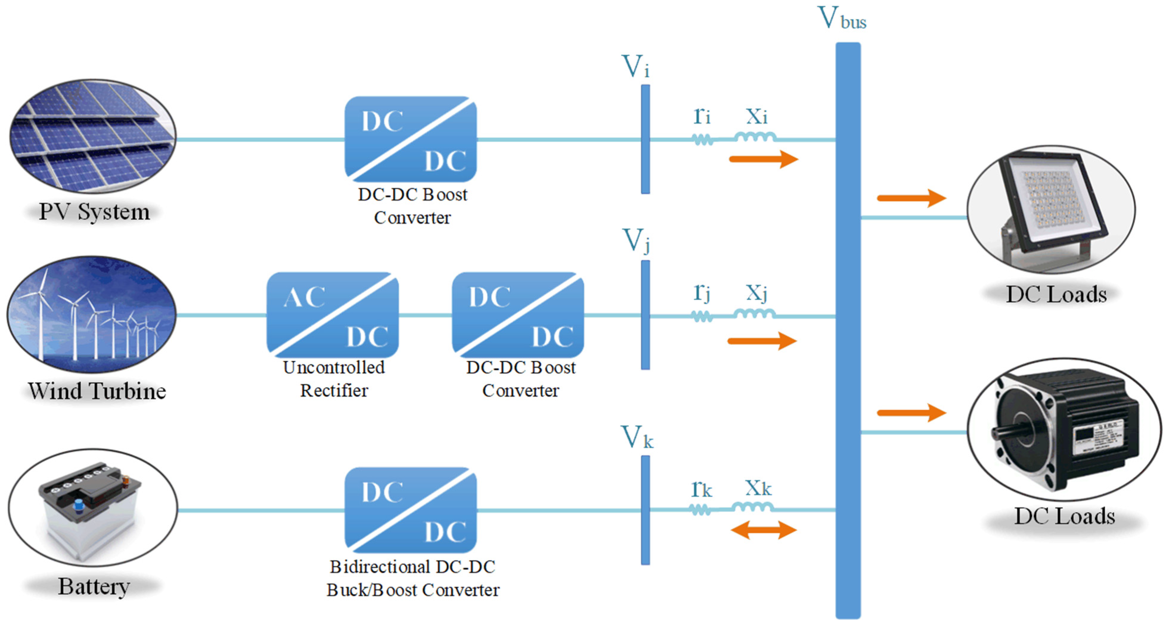
The general structure of the microgrid, comprising renewable energy sources (a PV system and a wind turbine) and energy storage systems, is illustrated in
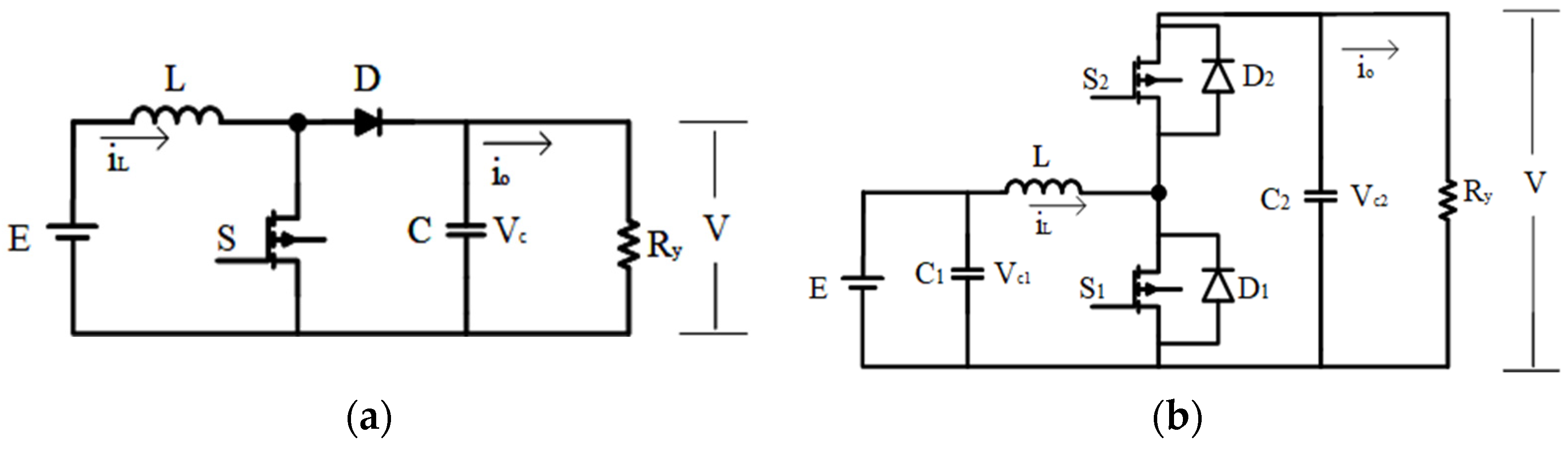
Figure 1. The sources and loads within the microgrid are connected in parallel to the DC bus. For connecting the wind turbine and PV system to the DC bus, DC–DC boost converters are employed, while bidirectional buck/boost DC–DC converters are utilized for connecting the battery groups to the DC bus. The equivalent circuit of the DC–DC boost converter is presented in
Figure 2a, and the equivalent circuit of the bidirectional DC–DC buck/boost converter is provided in
Figure 2b.
The control objective of the microgrid is to regulate the power states between the sources while maintaining the bus voltage at nominal values. Effective control of the power converters plays a crucial role in achieving these objectives. Power converters, composed of an inductor and a capacitor filter, are governed by the control of the duty cycle
d. The dynamics of energy conversion are represented by the inductor current
iL and the capacitor voltage
V [
40]. The operational state of the battery, whether in charge or in discharge, significantly influences the power management of the microgrid, thereby altering the dynamic equations of the system. During battery discharge, the bidirectional buck/boost DC–DC converter operates in boost mode and exhibits characteristics similar to other boost converters. The state space representation of the boost DC–DC converter equations is provided below [
40,
41]:
where
V is converter output voltage,
E is converter input voltage,
iL is inductor current,
L is inductor inductance,
R is resistor reactance, and
C is capacitor capacitance. While the battery is operating in charging mode, the bidirectional DC–DC buck/boost converter operates in buck mode. The state-space representation of this equation is given below [
42]:
As evident from the state-space equations, the battery transitions from the source state to the load state with a change in the direction of the current. Consequently, by manipulating the voltage on the battery, it can be shifted between charge and discharge modes. The parameters of the designed DC–DC boost converter and bidirectional DC–DC buck/boost converter are detailed in
Table 1.
3. Developed Distributed Secondary Control
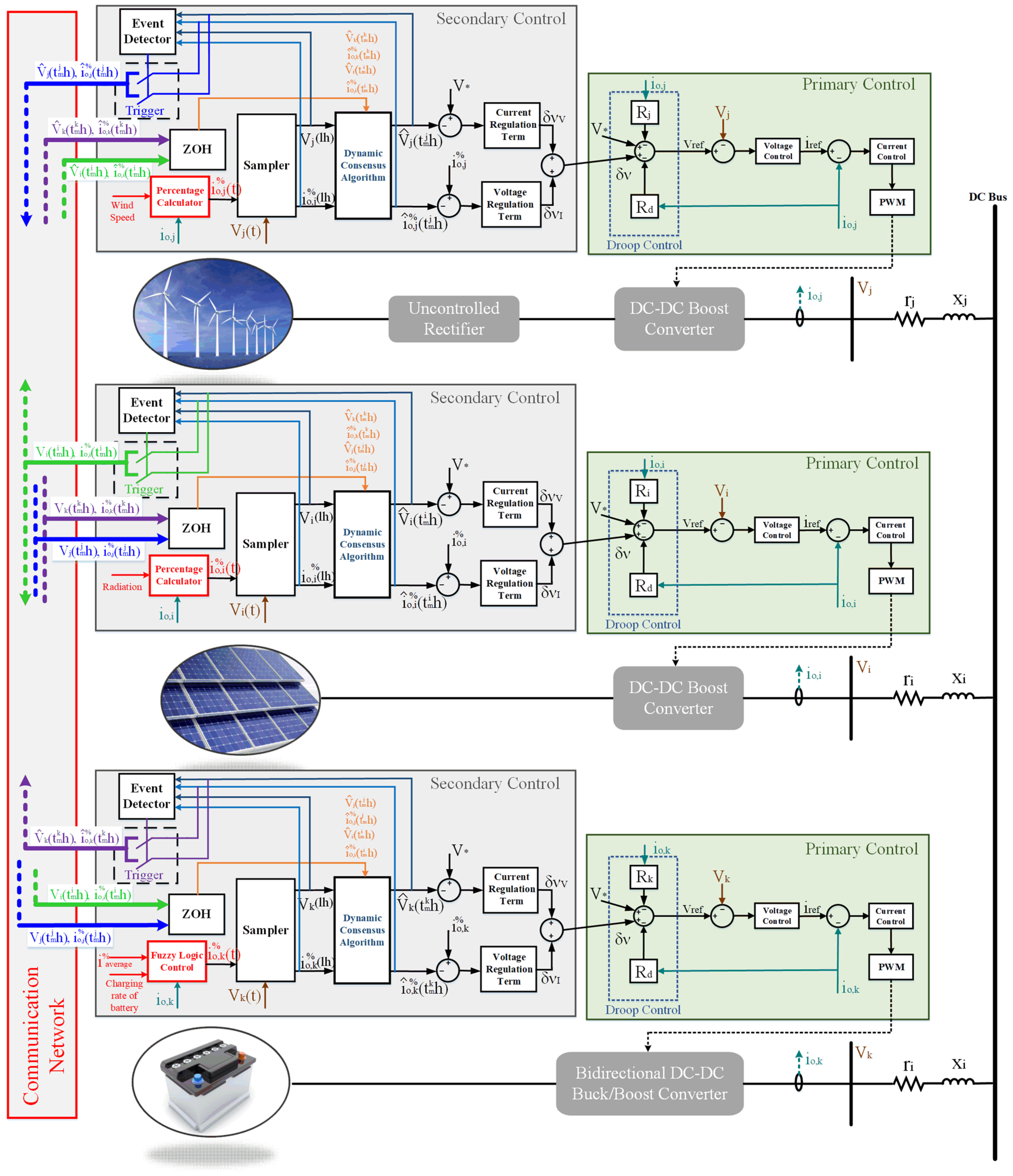
Distributed secondary control stands out as a widely employed method for microgrids. This control methodology comprises multiple layers that operate at distinct time intervals. Among these layers, primary control serves the purpose of achieving proportional current sharing among sources, using local information. While primary control effectively ensures proportional current sharing, it may lead to voltage deviation. To address this, the secondary control layer is implemented to rectify the voltage deviation. In this particular study, the secondary control layer is enhanced by integrating energy management algorithms, aiming to optimize source utilization in conjunction with the voltage- and current-controlling layers. The developed distributed secondary control scheme is illustrated in
Figure 3.
3.1. Primary Control Based on Droop Control
As depicted in
Figure 1, the energy sources within the proposed DC microgrid are linked to the DC bus (common connection point) through DC–DC converters. Droop control, a widely adopted method, is utilized to facilitate power sharing among sources in a microgrid where sources are interconnected in parallel [
43]. In this approach, a virtual resistor is introduced to achieve proportional power sharing [
10]. The power-sharing ratios among sources are adjusted based on the designated virtual resistor. When sources are situated at varying distances from the DC bus, their line impedances differ, subsequently influencing proportional current sharing. The formula below illustrates the calculation of the new reference value, accounting for the virtual resistance and line impedance (considering the ohmic resistance value) [
44]:
where
V* is reference output voltage,
Vbus is the bus voltage of the microgrid,
Rd is the virtual resistance,
ri is transmission line resistance and
io is the converter output current. Since all sources are connected to the common DC bus:
If the equation is simplified:
If
, the
r value in the formula can be ignored. Thus, the following equation can be obtained:
The chosen values for the virtual resistors have a direct impact on the current supplied by the sources to the loads, as indicated in the formula. Opting for a larger virtual resistance value facilitates more accurate power sharing among sources in the microgrid. However, this choice tends to increase the deviation of bus voltage. In contrast, selecting a smaller virtual resistance value aims to reduce bus voltage deviation. Nevertheless, in this scenario, there is a risk of disrupting proportional power sharing among sources. The power-transfer ratios of the sources are fine-tuned based on the determined virtual resistance values.
Primary control encompasses droop, current, and voltage control loops. In this context, the voltage loop governs the output voltage of the converters, while the current loop protects the sources from overcurrent. Both loops are regulated through proportional–integral (PI) control. PI control is commonly employed in voltage and current control loops as it ensures zero steady-state error and enhances the transient response of the system [
16]. The equations utilized for controlling the current are presented in Equation (7), and those employed for controlling the voltage are provided in Equation (8) [
10]:
where
d is the duty cycle,
iref is the current reference produced by the voltage control,
vref is the reference voltage produced by the droop control, and
V is the converter output voltage.
Kic,p and
Kpc,p are the integral and proportional coefficients of current control;
Kiv,p and
Kpv,p are the integral and proportional coefficients of voltage control.
3.2. Proposed Distributed Secondary Control
Droop control facilitates proportional current sharing among sources without the need for communication. However, the introduction of virtual resistance leads to deviation in the bus voltage. Furthermore, as the virtual resistance values are predetermined and fixed, droop control proves inadequate in ensuring proportional power sharing among intermittent generation sources. To address these limitations and distortions caused by the primary controller, a distributed secondary controller has been developed. This secondary controller has two main goals: first, to rectify the voltage deviation in the bus, and second, to readjust the proportional current sharing based on the changing power generation values of the sources. The correction term generated by the secondary control is added to the droop control, aiming to rectify the voltage deviation of the bus and reorganize the proportional current sharing [
14]:
where
is the correction value of the
ith controller. To adjust the bus voltage value to the reference value:
This added correction term includes both voltage correction and current correction terms. The correction term is obtaining by using the following equation:
where
is the voltage correction term and
is the current correction term. A voltage regulation loop is established within the secondary control to correct the voltage deviation caused by the droop control. This regulation loop applies PI control to the difference between the reference voltage value and the estimated voltage value:
where
Kpv,s and
Kiv,s are the proportional and integral coefficients of the PI control in the voltage regulation loop.
is the estimated bus voltage of the
ith converter.
While the voltage control loop addresses the correction of voltage deviation, it introduces distortion in the current sharing. To mitigate this distortion and ensure accurate current sharing, the current control loop is employed in conjunction with the voltage control loop. Within the current control loop, current percentage values are utilized instead of actual current values. These current percentages are calculated taking into account the maximum current values provided by the sources. This approach enables the easy tracking of proportional power transfer from sources with varying power values. In the current control loop, the percentage current value of the source is subtracted from the estimated percentage current value of the microgrid. The resulting difference is fed into the proportional–integral (PI) control to generate the current correction term. The calculation of the current correction term is presented below:
where
is the percentage of the estimated output current of the converters and
is the ratio of the converter’s output current to the maximum current.
Kpc,s and
Kic,s are the proportional and integral coefficients of the PI control in the current regulation loop.
For intermittent generation sources such as PV and wind, it is crucial to regulate proportional power sharing based on the current generation values of the sources for the security of both the sources and the microgrid. To achieve this, the secondary regulation utilizes current percentages instead of actual current values. These current percentage values dynamically adjust power sharing in response to changing power generation levels from PV and wind sources. Additionally, employing current percentages eliminates the need to transmit power information from variable generation sources. The basis behind this approach is that the percentage value of the output current serves as an indicator of the load on the source. During operation, the current percentage values of the source increase when the generation power decreases due to environmental conditions such as wind speed or irradiation. The control system responds by reducing the power transferred from the source to compensate for the rising percentage of current. This equalization based on current-percentage logic helps prevent source overloading and mitigates the negative effects caused by power reduction in the microgrid. The calculation of the percentage value of the output current for sources is expressed as follows [
14]:
where
io represents the measured current value and
imax is the maximum current that the source is capable of delivering at that specific time. Indeed, the determination of
imax takes into account the dynamic nature of power parameters, which are subject to variations in radiation, temperature, and wind speed for both wind and PV sources.
where
Pmax represents the maximum power that the source can generate at that moment and
V denotes the output voltage of the converter. Given that
Pmax is contingent upon varying factors such as radiation, temperature, and wind speed for PV and wind sources, it necessitates the real-time calculation of power generation information for these sources. Consequently, algorithms have been incorporated into the secondary control to compute the power generation amounts of PV and wind at any given moment. The maximum power generated by the wind turbine, taking into account the wind speed, is computed using the formula presented below [
45]:
where
ρ is the density of the air,
A is area of the wind turbine blades,
cp is the Betz limit and
v is the wind speed. Changes in parameters such as wind speed, radiation, and temperature significantly impact the generated power. Given the substantial influence of wind speed on power generation, adjustments to wind turbine power have been aligned with changes in wind speed in this study. The power produced by the PV system fluctuates with variations in radiation and temperature and is determined using the formulas provided below [
46,
47]:
where
T is PV panel temperature,
Tref is the reference temperature,
G is the irradiation of the PV panel,
Gref is the reference irradiation,
KT is temperature factor of the short-circuit current,
Isc is the short-circuit current at 25 °C and 1000 W/m
2,
Voc is the open-circuit voltage of the PV panel,
q is the electric charge,
k is the Boltzmann constant,
A is the diode quality factor,
VD is the diode voltage,
Rp is the parallel resistor,
Ipv is the output current of the cell, and
Vpv is the output voltage of the cell [
47].
3.3. Dynamic Consensus Algorithm
The dynamic consensus algorithm is employed to achieve consensus on a specific value [
48,
49]. In this approach, an agent is instantiated within each controller, and these agents have the ability to communicate with their neighboring agents, facilitating the estimation of the average information within the system. Each agent, integrated into the dynamic consensus algorithm, acquires estimated information from its neighboring agents. Subsequently, it derives its own prediction data based on the received estimates and aggregates the differences obtained. The estimated average value for this node is then computed by summing these aggregated values with the measured value of this particular node [
13,
49]. In this paper, the dynamic consensus algorithm is utilized to estimate the average bus voltage and average percentage current values of the sources.
where
is the bus voltage estimated by the
ith controller,
Vi is measured bus voltage of the
ith controller,
is the bus voltage estimated by the
jth controller, and
aij is the weight of communication. In the current consensus formula,
is the percent value of the output current estimated by the
ith controller,
is the percent value of the measured current of the
ith controller, and
is the estimated percent current value of the
jth controller. These equations reveal that when a node undergoes a change, the local estimation responds promptly, and this change is disseminated throughout the communication network, influencing all other estimations.
For the dynamic consensus algorithm to yield accurate estimates at node points, it is imperative to establish a precisely crafted communication network structure [
49]. The modeling of the communication network structure employed in this study was accomplished using graph theory. Graph theory proves crucial in achieving convergence and dynamic analysis by delineating the communication structure of systems [
48].
In this theory, controllers are expressed by nodes, and communication links between controllers are expressed by edges. The whole system is modeled as G = (Ɲ, ε). Ɲ = {Ɲ
1, Ɲ
2, …, Ɲ
n} represent the nodes. The connection between the nodes is denoted by ε ⸦ Ɲ × Ɲ. The communication weight of the whole system can be represented by the adjacency matrix A
G = [a
ij] ∈ ℝ
MxM. If a
ij > 0, there is communication between Ɲ
i and Ɲ
j. If there is no communication between two nodes, a
ij = 0. All neighbors of node
i are denoted by M
i = {j|(Ɲ
j, Ɲ
i) ∈ ε}. If
j is a member of
Mi, then node
i receives information from node
j [
50,
51]. The data entry numbers of all node points in the design are expressed with the input degree matrix D
in. This matrix is diagonal. The Laplacian matrix is obtained by subtracting the adjacency matrix from the input degree matrix as shown in the equation below [
50,
51].
The Laplacian matrix holds significance in graph theory, encapsulating information about the degree of each node and its connectivity with other nodes in the neighborhood. This matrix is square, with dimensions equal to the number of nodes present in the graph. The Laplacian matrix for this study was derived as follows:
In this matrix, global dynamics are determined. If the communication is bidirectional, meaning DG
in and DG
out are equal to each other, the Laplacian matrix is in equilibrium. In other words, communication connections are established bidirectionally [
49,
51].
Owing to the dynamic consensus algorithm, the secondary control exclusively exchanges data among specified controls, leading to the use of the peer-to-peer communication protocol in the survey. This protocol involves the direct exchange of data between users, eliminating the need for a central server. Additionally, this protocol was selected for the study because it facilitates synchronous and nonperiodic communication between peers, essential for event-triggered communication.
To support the peer-to-peer communication protocol, LoRa modules were incorporated in the study due to their advantages such as a broad communication network, bidirectional data exchange, cost-effectiveness, and low energy consumption. The E32 433T20d LoRa modules were utilized in the study, with configuration settings detailed in
Table 2.
3.4. Fuzzy-Logic-Based Energy Management System
Fuzzy logic control (FLC) is a control system designed to transform nonlinear functions into simple rules by incorporating measurements, human knowledge, and extensive experience [
52]. Unlike other nonlinear controllers, FLC operates without the necessity of a mathematical model, making it more adaptable to nonlinear functions [
53]. Moreover, FLC can facilitate control without relying on previous data, distinguishing it from other smart controllers [
54]. Notably, this control system is easily designed with minimal knowledge about the system model [
55] and exhibits resilience in handling noisy sensor data and input signals, avoiding abrupt changes in control outputs [
53]. FLC is employed as an alternative control approach to offer a more robust solution to control challenges in microgrids [
55].
Voltage stability in islanded microgrids poses a significant challenge. The power converters within the microgrid must operate in voltage control mode to address this issue. However, operating converters connected to intermittent generation sources such as PV systems and wind turbines in voltage control mode can lead to inefficiencies. To enhance the efficiency of renewable energy sources, maintain microgrid voltage stability, and prevent overcharging and discharging of the battery pack, a fuzzy-logic-based energy management system has been developed. Positioned within the secondary control layer of the battery group controller, this FLC system regulates the output of the battery and other sources based on the output of the renewable energy sources, the load requirements, and the battery’s state of charge.
The fuzzy logic controller comprises four components: a fuzzifier, a fuzzy rule table, a fuzzy inference model, and a defuzzifier [
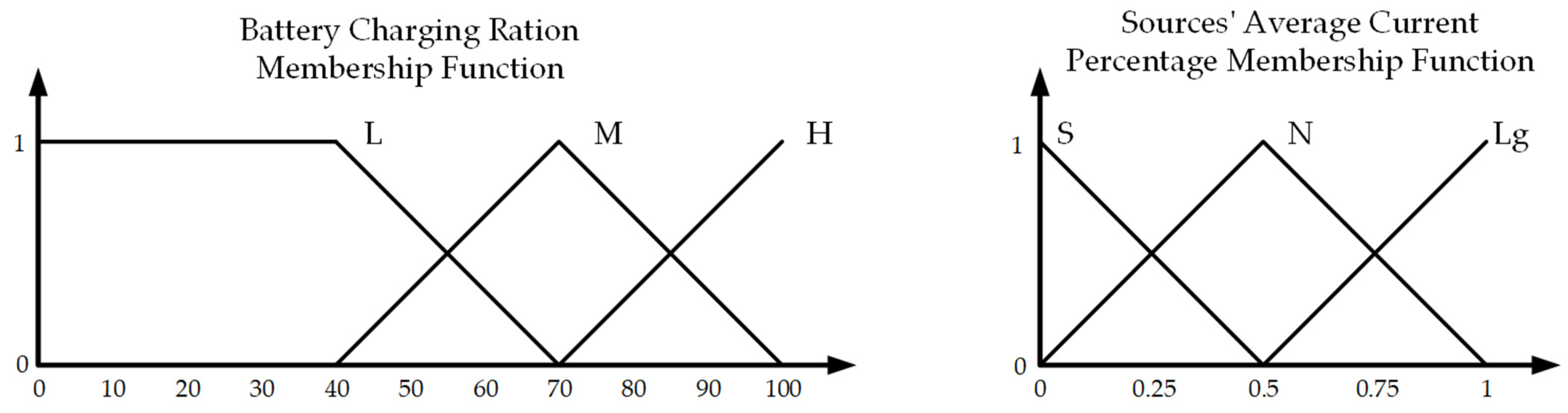
56]. This control method converts real numerical data into linguistic expressions that determine the membership degrees of input membership functions through the fuzzification unit. In this study, two triangular input membership functions were generated for control, as illustrated in
Figure 4. One of these membership functions represents the battery charge ratio, while the other corresponds to the percentage of source output current. Three input parameters were defined for the battery charge rate input: Low (L), Medium (M), and High (H). Additionally, Small (S), Normal (N), and Large (Lg) input parameters were created for the output current percentage of the sources. Triangular membership functions were chosen in this study for their simplicity, adaptability, stability, and ease of interpretation [
53].
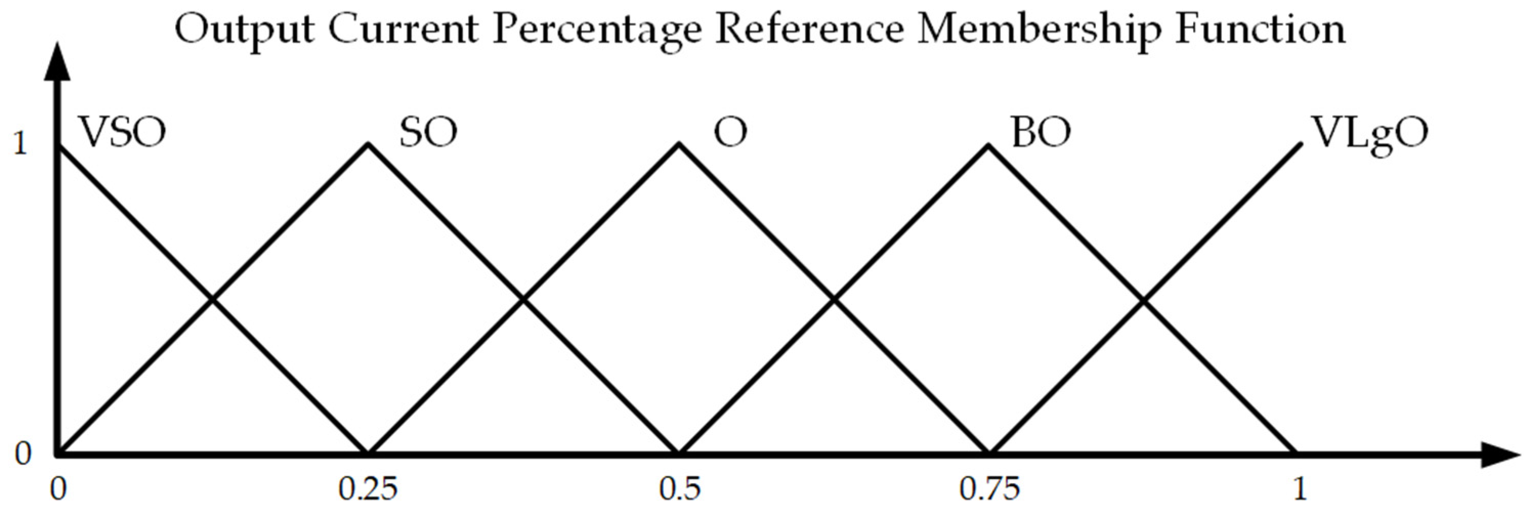
As depicted in
Figure 5, an output triangular membership function has been defined to encompass the output current percentage data that provides the participation information of the sources. For the output membership function, five output parameters were established: Very Small Output (VSO), Small Output (SO), Output (O), Large Output (LgO), and Very Large Output (VLgO).
A fuzzy logic rule table, which contains IF-THEN rules [
57], is utilized to establish connections between the output and input membership functions.
Table 3 presents the fuzzy logic rule table.
The rules are as follows: if x1 is and x2 is , then zj is Bj,
where
x1 and
x2 are inputs of the fuzzy logic system;
zj is the output of the fuzzy logic system; and
,
and
Bj are fuzzy logic membership functions. The output fuzzy logic membership function is determined from the input fuzzy logic membership functions using the Mamdani inference model. Defuzzification is performed using the centroid technique, which determines the percentage value of the source output current and the operating state of the sources. The mathematical expression of the fuzzy logic system is as follows [
57,
58]:
where
is the fuzzy membership function and
is the weight vector. Equation (23) can also be expressed as follows [
56]:
where
is the fuzzy basis function, defined as
, and
is the weight vector matrix, defined as
. Thus, the mathematical expression of the created fuzzy basis function is as follows:
3.5. Sampled-Data-Based Event-Triggered Control
Event-triggered control has recently become widely used in microgrid control, reducing the data load on the communication network and enhancing microgrid security [
59]. In this method, data transfer occurs based on a criterion rather than periodic data transfer [
60]. However, event-triggered control can lead to an infinite number of triggers in a finite time, resulting in Zeno behavior. This increases the computational load on the controllers and adversely affects their operation [
37]. In hierarchical control structures, the upper control levels of the controller operate within larger time intervals [
16]. Therefore, in this study, the operating time intervals of the secondary control level were adjusted using the sampled-data mechanism. The sampled-data mechanism makes it possible to obtain a limited quantity of data even in the case of continuous communication, reducing the computational burden of the secondary control. Subsequently, the event-trigger control added to the sampled-data mechanism further filters the communication data [
61]. Thus, even if the event-triggering condition is not correct, the minimum sampling period is always greater than zero (
h > 0), avoiding Zeno behavior [
37,
38,
39]. With the addition of sampled-data-based event-triggered control, the dynamic consensus algorithm only takes data when the event-trigger condition is met and performs the computation [
40]. The synchronous sampling time sequence is defined as
Ts = {
lh|
l = 0,1,2,…,}, and the time sequence of event-triggered instants for the
ith node is defined as
Ti = {
timh|
m = 0,1,2,…,}.
According to this approach, the dynamic consensus algorithm is calculated based on the last event time data as follows:
where
represents the estimated values of the
ith controller,
, represents the measured values of the
ith controller,
represents the estimated values of
jth controller,
is the last event time of the
jth controller, and
is the last event time of the
ith controller. Communication does not need to be synchronized with the event-triggered control method. According to its event-triggered states, each controller sends information. The event that triggers communication is determined by the local measurement values, as there is no communication in the steady state. For this reason, event-trigger states are created according to the
i% and
V values. Two different trigger conditions are used for both current and voltage:
The parameters
eerror and
ierror are employed to prevent unnecessary triggering of events due to measurement errors and to adjust energy stability in the microgrid. Opting for higher values for these parameters diminishes the stability of the bus voltage and the sensitivity of proportional current sharing, but it concurrently reduces the data in the communication network. Conversely, smaller selected values for these variables heighten the sensitivity of voltage stability and proportional current sharing, albeit they increase the volume of data in the communication network. The event-triggered algorithm for the sampled data-based control method is given in Algorithm 1 as follows:
| Algorithm 1 Event-Triggered Algorithm of Sampled-Data-Based Event-Triggered Control |
Step 1: Measure the output voltage and current of the converter.
Step 2: Calculate the percentage value of the output current. (Equations (14), (15), (17) and (18) are used for the PV system controller, Equations (14)–(16) are used for wind turbine controller)
Step 3: Loop:
If Has any data come from the neighbors?
Then
Update latest data from neighbors
End If
Step 4: Calculate the estimated average values of current and voltage with Equation (26)
Step 5: Loop:
If Are the event trigger conditions in Equation (27) or Equation (28) satisfied?
Then
Go back to Step 1.
Else
Send last calculated values to neighbors.
Go back to Step 1.
End If |
The controller updates its own event times and the event times of its neighbors with the estimated values obtained through the dynamic consensus algorithm. Consequently, alterations in data from one controller lead to the updating of estimated data in other distributed systems. To achieve a consensus, controllers must depend on the most recently updated data from their neighbors.
4. Experimental Results
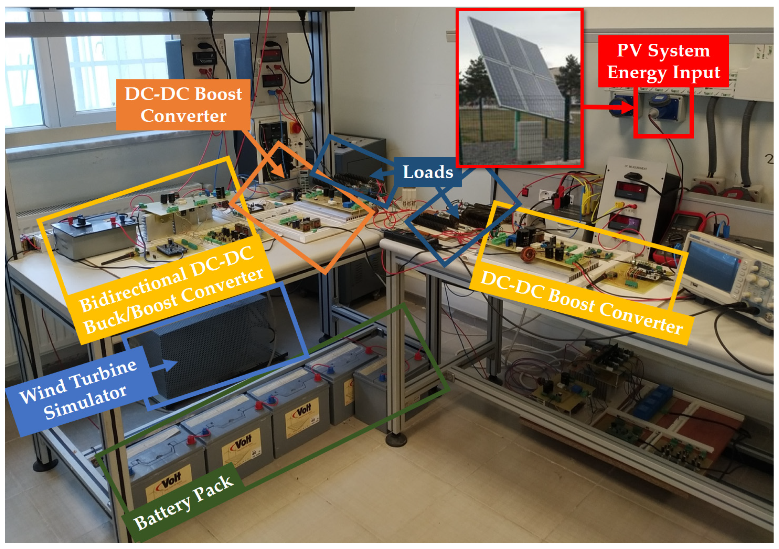
An islanded DC microgrid was designed and implemented, as illustrated in
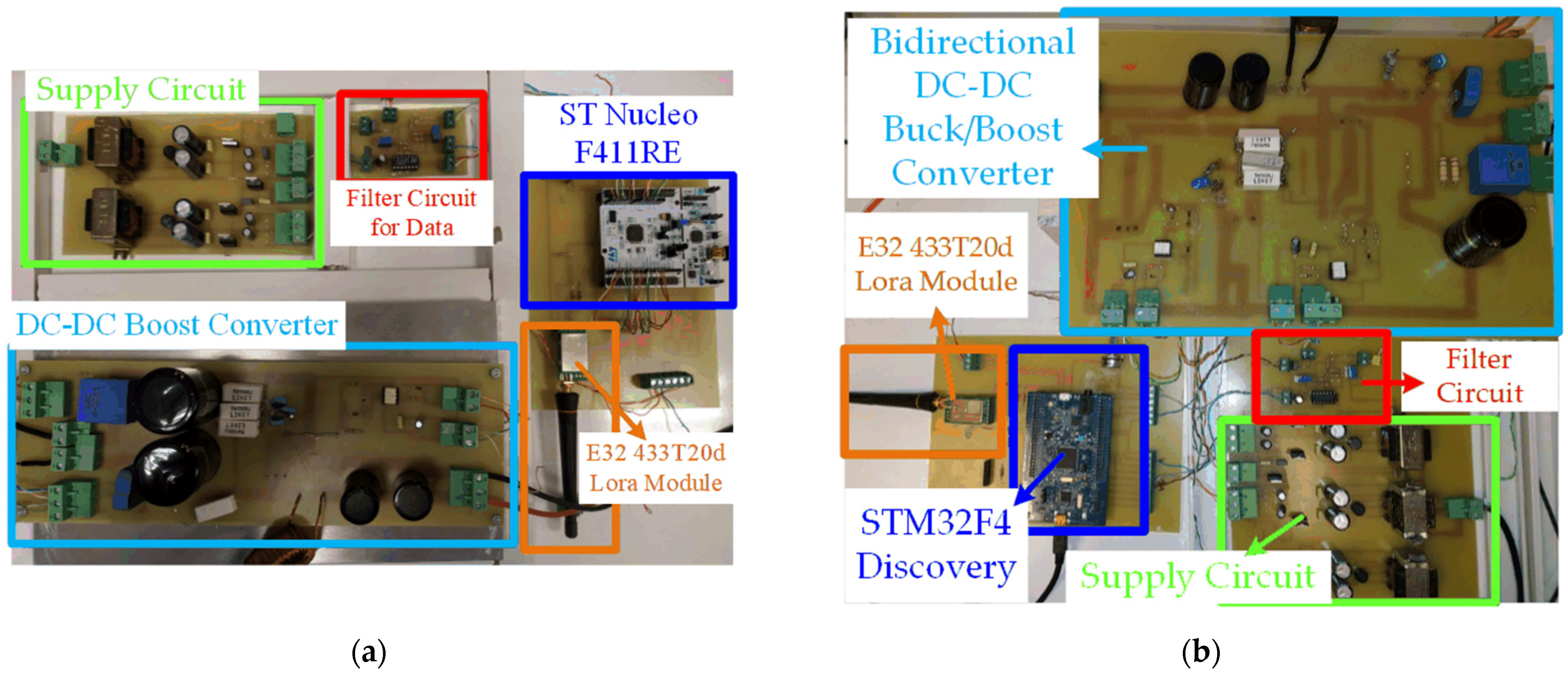
Figure 6, to assess the performance of the event-triggered distributed secondary control method developed by incorporating an energy management algorithm. This microgrid features a 200 V DC bus with sources and loads connected in parallel. The microgrid sources consist of a 1 KW PV system, a 1.2 KW wind turbine simulator, and a battery group with values of 60 V and 40 A. Energy from the PV system and the wind turbine simulator is transferred to the microgrid’s DC bus through DC–DC boost converters. The DC–DC boost converter units for the PV system and wind turbine are designed as depicted in
Figure 7a, with control managed by ST Nucleo—F411RE Development Kit controllers which are manufactured by STMicroelectronics company (Plan-les-Ouates, Switzerland). Additionally, a bidirectional DC–DC buck/boost converter, shown in
Figure 7b, connects the battery pack to the microgrid’s DC bus. Control for this bidirectional converter is implemented using an STM32F4 Discovery controller which is product of STMicroelectronics company. The supply circuits within the converter units provide power to an LEM LTS25-NP current sensor, an LV-25P voltage sensor, and a TLP250 optocoupler, amplifying the control signal and is a product of Toshiba Company (Kawasaki, Japan) This current sensor and voltage sensor are manufactured by LEM Company (Meyrin, Switzerland). Filter circuits are incorporated to mitigate noise in the measurement information obtained from current and voltage sensors. The E32 433T20d LoRa modules facilitate data exchange among controllers through a peer-to-peer communication protocol, with a communication range of up to 3 km in open areas.
To demonstrate the effectiveness and the performance of the developed control algorithm, a systematic evaluation was performed, and the results are presented herein. The operational phases involved initially applying traditional distributed secondary control to control the designed DC microgrid. Following this, experimental investigations were executed by integrating an energy management system, devised using fuzzy logic, into the distributed secondary control. Ultimately, the experimental phase concluded with the incorporation of event-triggered control into the microgrid’s control mechanism.
4.1. Distributed Secondary Control
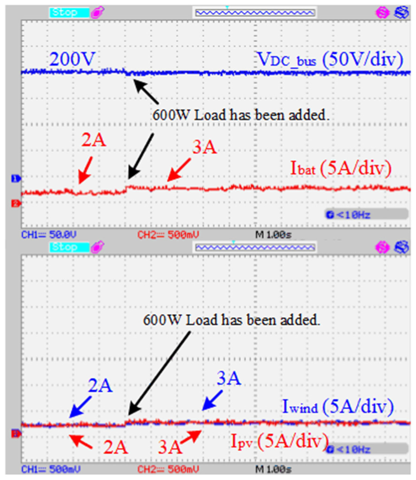
In this experimental study, the DC microgrid was controlled using traditional distributed secondary control, and communication between controllers was continuously adjusted at 100 ms time intervals. The secondary controller layer incorporated both voltage regulation control and current regulation control, generating a correction value for the primary control. Regarding the experimental results presented in
Figure 8, the microgrid initially operated with a 1200 W load, and the current was evenly shared among the sources. Subsequently, a 600 W load was added to the microgrid. The results show that, in response to the added load, the voltage remained constant at 200 V, and the new load was equally distributed among the sources. The voltage regulation loop within the secondary control maintained the voltage at 200 V, while the current regulation loop ensured equal current sharing among the sources. The experimental results indicated that the current control loop in the secondary controller successfully achieved equal power sharing among the sources.
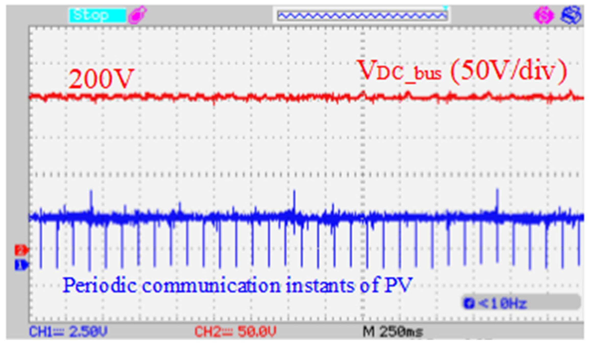
The PV system controller consistently transmits data at 100 ms time intervals, as depicted in
Figure 9, while the microgrid operates under traditional distributed secondary control.
4.2. Distributed Secondary Control with Fuzzy-Logic-Based Energy Management System
As indicated in the previous section, traditional distributed control is highly effective in power sharing among sources and maintaining voltage stability. However, this control methodology proves inadequate for microgrids incorporating intermittent generation sources and energy storage devices such as batteries. It does not guarantee that the battery will transition between charging and discharging modes in alignment with the microgrid’s power status, nor does it ensure power sharing with intermittent sources based on their power status. By introducing the fuzzy-logic-based energy management algorithm and percentage calculators into the event-triggered distributed secondary control, power sharing among resources is orchestrated in accordance with the current power values of the sources and the state of charge of the battery. The microgrid was subjected to various scenario studies to showcase the efficacy of the proposed energy management system, and the results are shared herein.
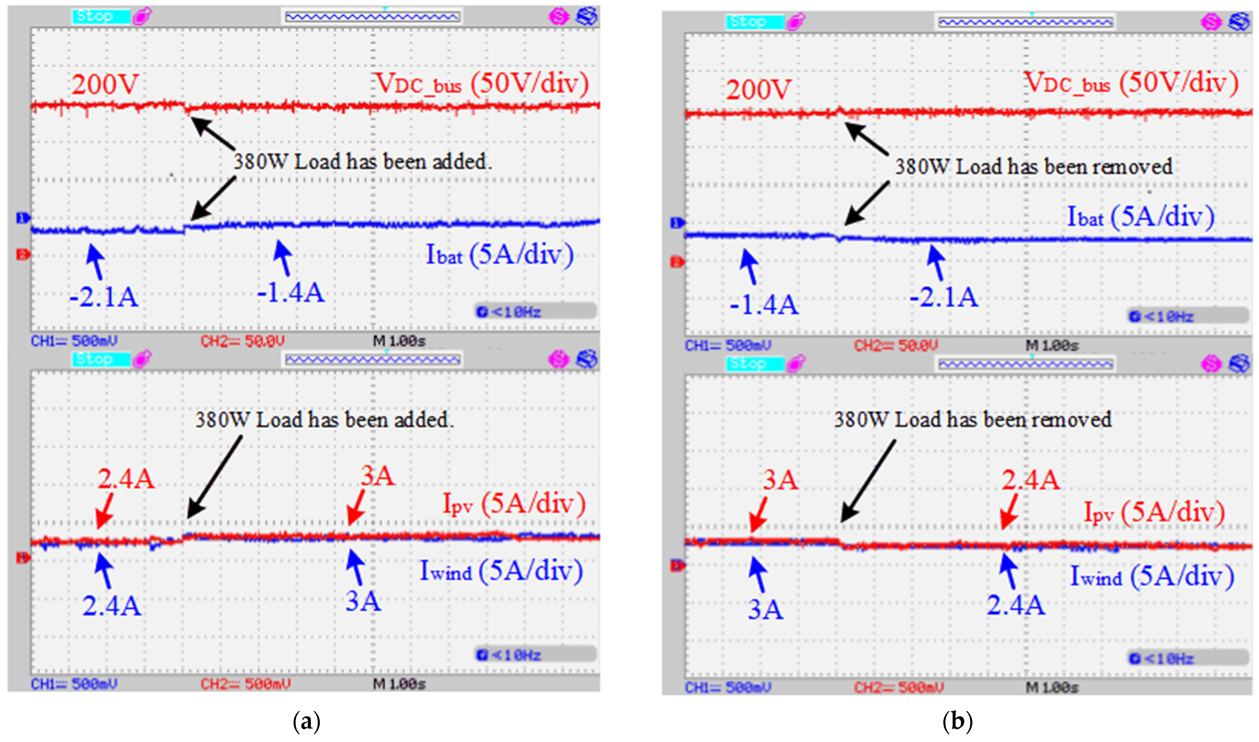
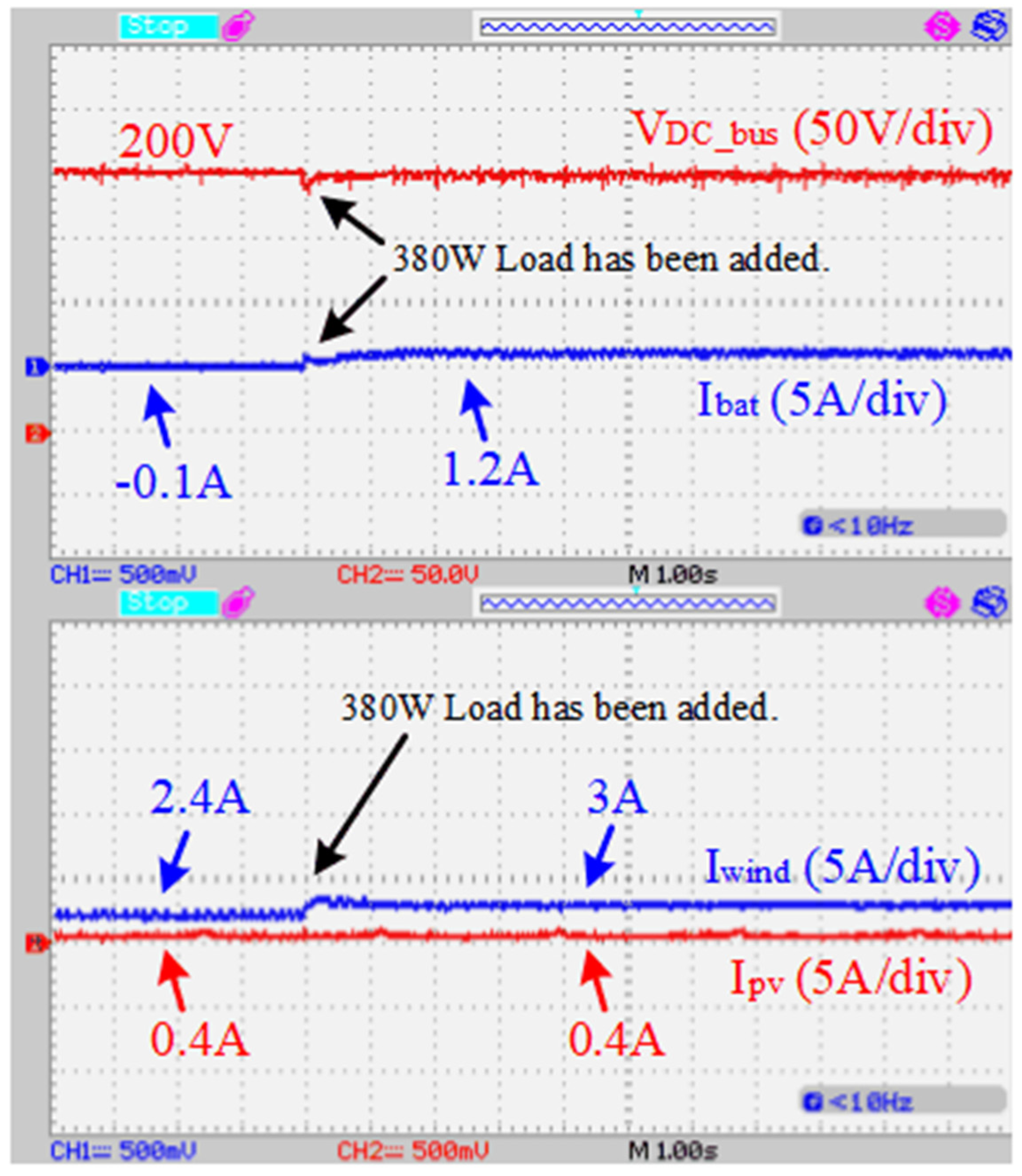
In this experimental study, the operational power of the PV system and the wind turbine were approximately 600 W. Initially, the microgrid carried a load of 540 W, with the battery having a charge ratio of about 90%. Due to the high battery charge ratio, the charging current of the battery was limited to prevent overcharging. Consequently, the PV system and the wind turbine each contributed roughly 80% of their maximum power output. As the power production values of the sources were equivalent, the energy management system orchestrated the power transfer from both sources to the bus in an equal manner. Approximately 2.4 A of current was directed from the sources to the bus, with each source supplying around 480 W, of which 540 W served the loads and approximately 420 W was allocated for charging the battery. As depicted in
Figure 10a, an additional load of 380 W was introduced to the microgrid. With the augmented load, the wind and PV currents increased to roughly 3 A, compensating for the extra load by reducing the battery charging current from 2.1 A to 1.4 A. This strategy ensured that the bus voltage remained stable at 200 V, and power sharing in the microgrid was adjusted based on the power production status of the sources.
Figure 10b illustrates the study’s results after removing the additional 380 W power load from the microgrid. Since the power production values of the sources remained unchanged, the removal of the load restored power sharing among the sources to their pre-load-addition values.
In another scenario, the PV system operated under cloudy weather conditions, producing a maximum of 80 W of power. The wind turbine’s operating power was 600 W, and the battery charging rate was set at approximately 90%. Initially, the microgrid carried a load of 540 W. Given the 90% battery charge ratio, the fuzzy logic controller adjusted the wind turbine’s operating power to 80% to maintain voltage stability during sudden load changes. As depicted in
Figure 11, the battery charging current was reduced by 0.1 A to supply power to the microgrid loads. Subsequently, a 380 W load was introduced to the microgrid. With the added load, the wind turbine’s output current increased by 3 A. However, the solar panel, producing power at its maximum capacity, could not contribute power to the added load. The battery compensated for the remaining required power, with the battery current rising from −0.1 A to approximately 1.2 A. Consequently, voltage stability was achieved as the wind turbine and the battery promptly responded to the added load, ensuring stability even when the PV system could not contribute due to its inability to produce power.
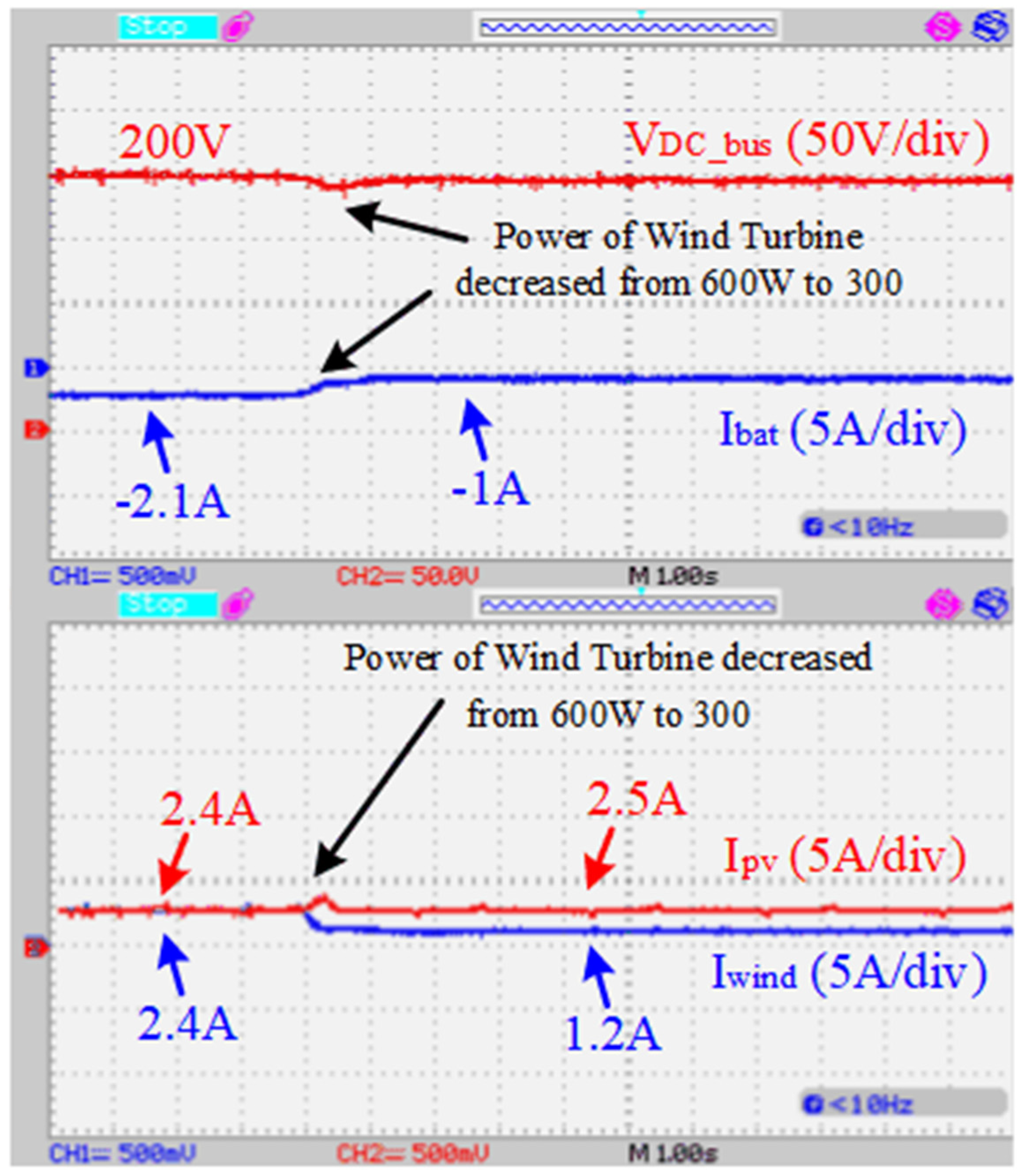
As a further scenario, the microgrid’s performance was observed as the power of the wind turbine decreased from 600 W to 300 W. The power output of the PV system remained around 600 W throughout the scenario, and the battery charging rate was approximately 90%. The load power was kept constant at 540 W during the experimental study. Initially, since the power outputs of the solar panel and wind turbine were equal, both sources contributed approximately 2.4 A of current. As depicted in
Figure 12, as the wind turbine’s power decreased, the current supplied by the wind turbine to the microgrid also dropped. To maintain voltage stability, the diminishing current from the wind turbine was compensated by the PV system and the battery. Given the PV system’s ability to respond rapidly to power changes, it initially maximized its current level. Subsequently, as the battery supplied power, the PV system adjusted itself to operate at roughly 80 percent capacity. The majority of the diminishing power from the wind turbine was compensated by the battery.
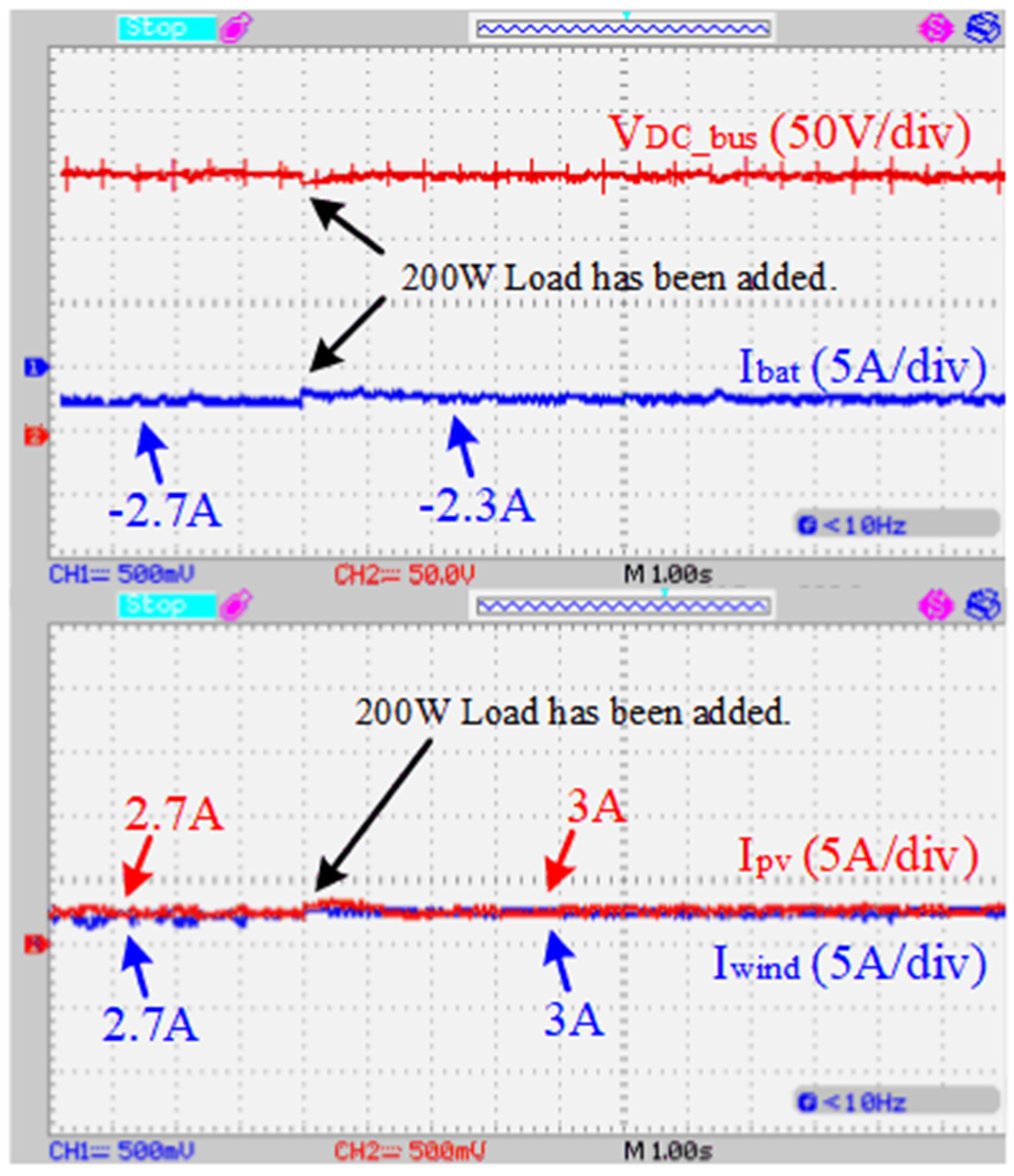
In the fourth experimental scenario, the battery charging rate was set to 80%, and the power values of the PV system and wind turbine were adjusted to be equal at 600 W. With the battery charging rate reduced to 80%, the fuzzy logic controller increased the contribution of the sources to approximately 90%. As depicted in
Figure 13, the microgrid initially operated with a load of approximately 540 W. The current values provided by the solar panel and wind turbine were approximately equal, around 2.7 A, and the battery drew approximately 2.7 A from the DC bus. In this operating state, a load of approximately 200 W was added to the microgrid. As a result, the current values from the solar panel and wind turbine increased to approximately 3 A. The remaining current required for the load was provided by the battery, and the battery charging current drawn from the DC bus decreased to 2.4 A. The experimental results demonstrate that the battery charging current was controlled by adjusting the participation rates of the sources according to the battery charging rate using the developed fuzzy logic controller energy management system.
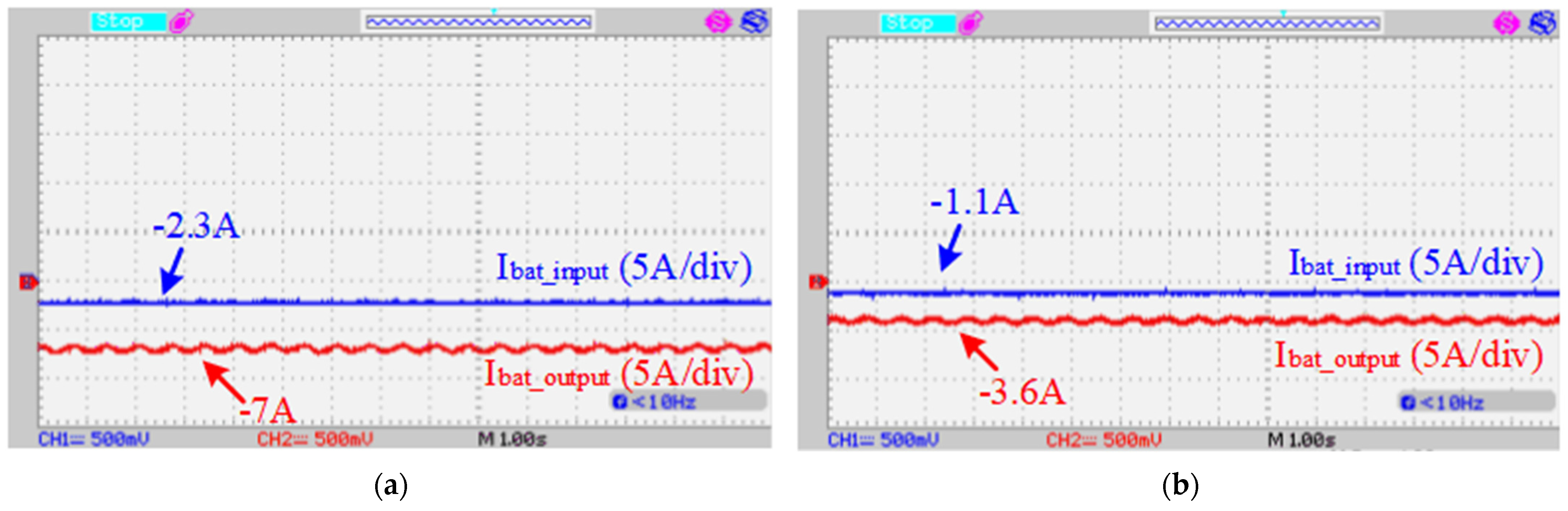
In the battery charging process, the bidirectional DC/DC buck/boost converter operates in buck mode, facilitating current flow from the bus to the battery. The charging current of the batteries fluctuates based on the power values generated by the renewables, the charging ratio of the batteries, and the microgrid load.
Figure 14 illustrates the battery charging current values at two different charging rates. In these experiments, the power values of the sources and the microgrid load were held constant, with both PV and wind generating approximately 600 W of power. In the result shown in
Figure 14a, with a battery charge ratio of about 90%, the bidirectional converter drew around 2.3 A current from the bus. The buck side of the bidirectional DC–DC buck/boost converter sent approximately 7.2 A current to the battery, charging it effectively. In the graph presented in
Figure 14b, when the battery charge ratio increased to about 95%, the current value drawn by the converter from the bus decreased to about 1.1 A. The battery was charged at around 4 A. The proposed controller effectively reduced the battery charge current as the battery charge ratio increased, protecting the battery from overcurrent and ensuring healthier operation.
The developed distributed secondary controller with an energy management algorithm was tested by operating at different power outputs from renewable energy sources and at different battery charge ratios, and the results showed that the controller managed the power flow at different operating values. Thus, it was shown that voltage stability and energy continuity were achieved in the island-mode DC microgrid with the proposed energy management system.
4.3. Distributed Secondary Control with Sampled-Data-Based Event-Triggered Control
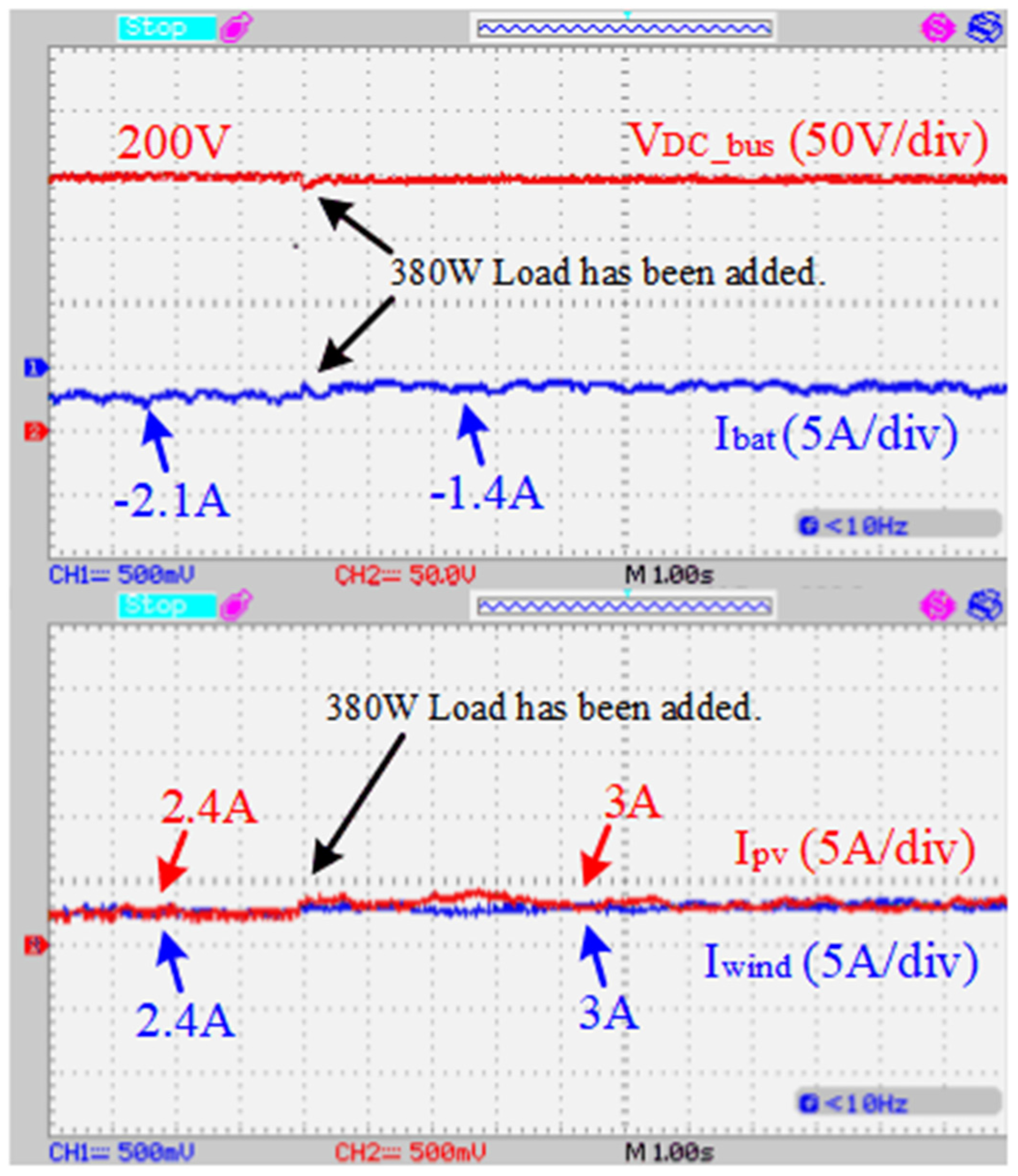
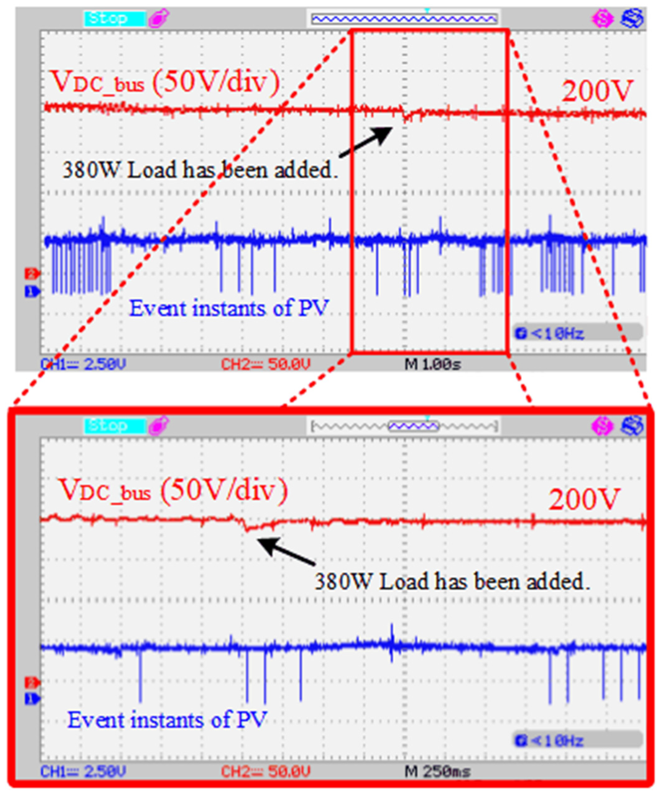
In this experimental study, sampled-data-based event-triggered control was added to the developed distributed secondary control method. To showcase the effectiveness of the proposed sampled-data-based event-triggered control, an experiment was conducted by introducing a 380 W load. The operating power of the PV system and the wind turbine was approximately 600 W, and the battery charge ratio was set to 90%. As shown in
Figure 15, the microgrid initially had a load of 540 W. In this case, the solar panel and wind turbine sent approximately 2.4 A current to the bus, while the battery drew around 2.1 A current from the DC bus. During the experimental study, a 380 W load was added to the DC bus of the microgrid. Upon examining the graph in
Figure 15, it is evident that due to the added load, there was a decrease of approximately 4% in the DC bus voltage, and the bus voltage returned to its reference value in approximately 250 ms. While the current values of the solar panel and wind turbine increased to approximately 3 A, the current drawn by the battery from the bus decreased to 1.4 A. The experimental study demonstrated that the current and voltage changes obtained with the event-triggered control were almost identical to the current and voltage changes in continuous communication, as shown in
Figure 10a.
Figure 16 illustrates the change in DC bus voltage and the moments of data transmission from the solar panel controller when microgrid control was facilitated using sampled-data-based event-triggered distributed secondary control. For this experimental study,
eerror was set to 2 V, and
ierror was set to 0.2 A. Upon examining
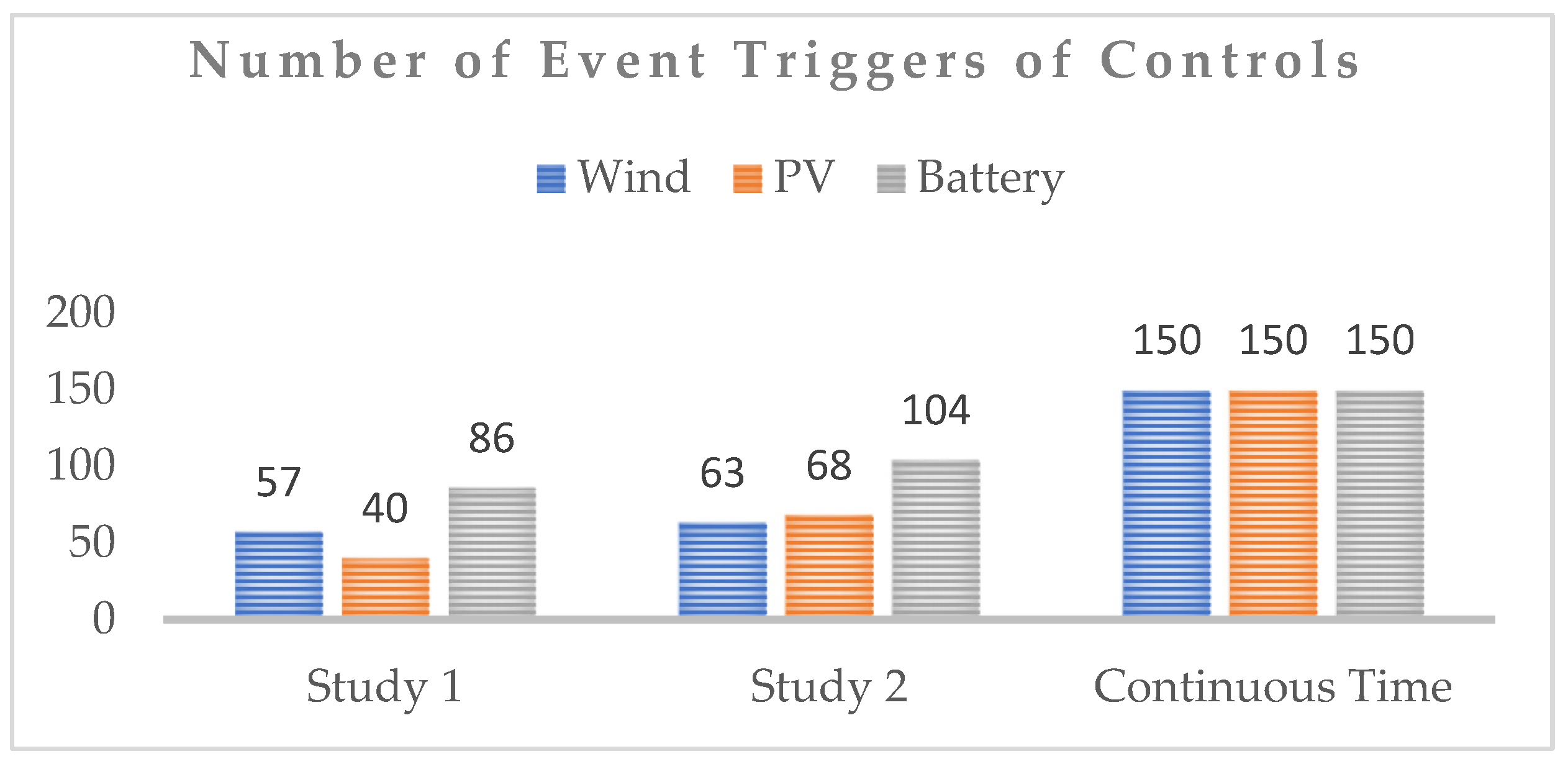
Figure 16, which spans 15 s during the addition of a 380 W load to the microgrid, it is evident that the solar panel controller sent data 40 times during this period. In contrast, without event-triggered control, the controller would send data 150 times in the same duration. Similarly, during this 15-s interval, the wind turbine controller sent data 57 times, and the battery controller sent data 86 times. Over the 15-s duration of the study, data transmission was reduced by approximately 59.4%. This underscores the significant reduction in the communication burden achieved by the proposed event-triggered distributed secondary control without compromising operational performance.
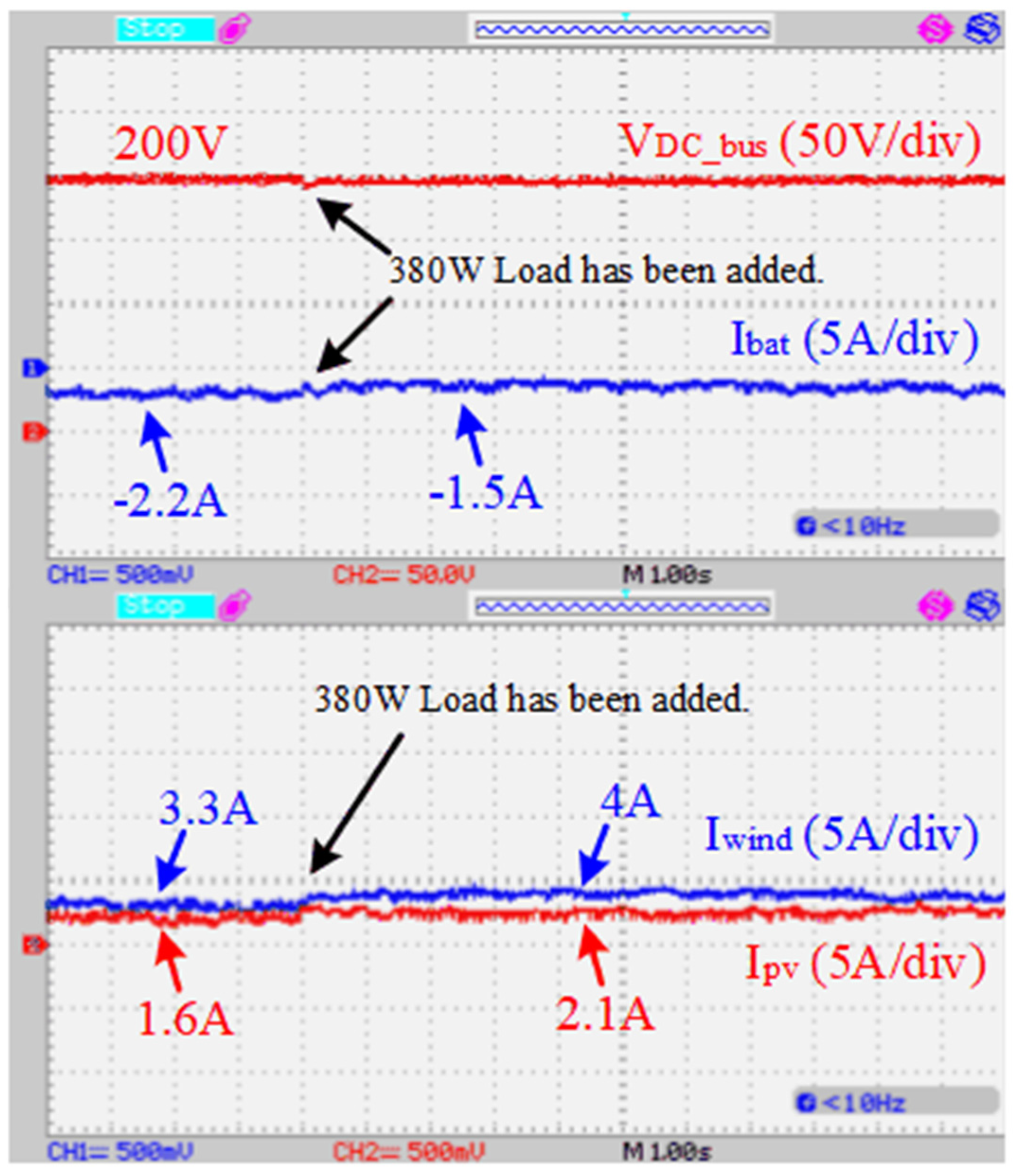
In another scenario utilizing event-triggered control, the wind turbine operated at approximately 800 W, and the PV system at around 420 W. Initially, a load of 540 W was present on the microgrid. The PV system supplied 320 W of power at a current of 1.6 A, while the wind turbine provided 660 W of power at a 3.3 A current. Both sources operated at around 80% capacity. During this period, 540 W of power was transferred to the loads, and 440 W of power was stored in the battery. Subsequently, a 380 W load was added to the microgrid. As depicted in
Figure 17, the battery charging current was adjusted to maintain system stability while the sources maximized power transfer with the added load. The bus voltage experienced a decrease of approximately 3%, but it quickly returned to the reference voltage value in approximately 200 ms. This scenario demonstrates the effectiveness of the event-triggered control in adapting to load changes while optimizing power transfer and ensuring stability in the microgrid.
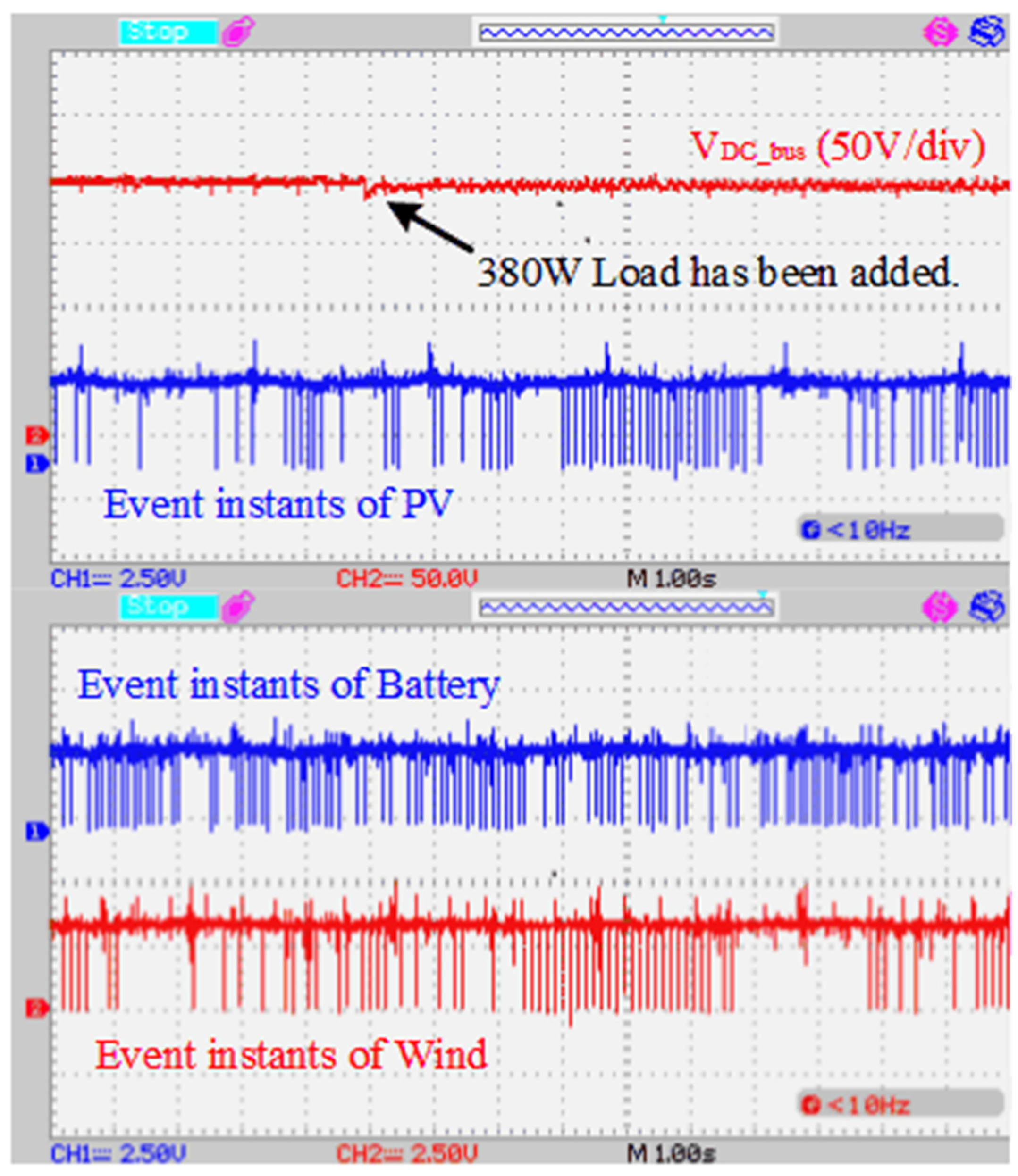
In the scenario where the PV system operates at 420 W, the wind turbine operates at 800 W, and the battery charge ratio is 90%,
Figure 18 illustrates the data transmission moments of the controllers. In this experimental study,
eerror was set to 2 V, and
ierror was set to 0.2 A. Upon examination of the oscilloscope screen, covering a 15-s time period in
Figure 18, it was observed that the solar panel controller transmitted data 68 times, the wind turbine controller 63 times, and the battery controller 104 times. In contrast, in the control operation without event-triggered control, each controller transmitted data 150 times in the same period. This represents a reduction in the quantity of data transmitted by approximately 47.2% during the 15-s period, highlighting the efficiency gains achieved through event-triggered control.
As seen in
Figure 19, experimental studies have demonstrated that incorporating sampled-data-based event-triggered control into the developed distributed secondary control reduces the communication load within the microgrid. The quantity of data was reduced by approximately 59.4% and 48.2% in two separate experimental studies with different power values for the sources, highlighting the effectiveness of sampled-data-based event-triggered control in minimizing the communication load within the microgrid. This reduction is significant for improving the efficiency and reliability of microgrid control while minimizing the burden on the communication network. The results confirm the benefits of the proposed control strategy in achieving efficient communication and control in the microgrid system.
With the event-triggered control added to the system, it was observed that the quantity of data sent by the controllers decreased by approximately 50% in microgrid control. This reduction decreases the dependence of microgrid control on communication and mitigates problems caused by communication issues in microgrid control. Considering some event-triggered studies in the literature, the sampling time was set to 50 μs in the study in [
32]. In the case of continuous communication, the controller sends 20,000 data per second. In the studies in [
4,
24], the sampling time was set to 1 ms. In these studies, 1000 data were sent per second in continuous communication. In the study in [
44], the sampling time was chosen as 0.1 ms. In continuous communication, 10,000 data were sent per second. Since the sampling time in the proposed control was 100 ms, data were sent 10 times in 1 s in continuous communication. By choosing a larger sampling time, the amount of data was greatly reduced. In addition, with the added event triggering, the quantity of data sent was reduced by an average of 50% compared to continuous communication.
Table 4 presents the power-sharing rates of the sources in the application studies conducted in this section. A comparison of the experimental results at a 540 W load in
Figure 10 and
Figure 13 reveals identical power production values for the PV system and wind turbine sources. In the study corresponding to
Figure 10, the battery charge ratio was 90%, while in the study corresponding to
Figure 13, it was 80%. At an 80% battery charge ratio, the battery drew 540 W of power from the bus, whereas at a 90% charge ratio, it drew 420 W from the bus. This observation underscores the fact that the charging ratio of the battery influences both the power drawn from the bus and the loading ratios of the sources. Upon comparing the experimental results in
Figure 15 and
Figure 17 under a 540 W power load condition, it is evident that the controller redistributed power, taking into consideration the power production status of the resources. With a battery charge ratio of 90%, the battery charged with approximately 420 W of power. As shown in
Figure 15, the wind turbine transmitted 480 W of power when operated at a maximum power of 600 W, with an 80% power transfer capacity. Similarly, the PV system operated at 80% capacity based on its maximum power generation value. Upon closer examination of the results in
Figure 17, it becomes evident that, while the battery drew a load of approximately 440 W, the loading values aligned approximately with 80%, as per the maximum power rates of the PV system and wind turbine.
5. Conclusions
In this study, the principal focus was on the implementation and assessment of an advanced event-triggered distributed secondary control system integrated with an energy management system for an islanded DC microgrid. The main objective was to optimize resource allocation while simultaneously maintaining voltage stability in the presence of renewable energy sources and an energy storage system. A secondary objective was to alleviate the data burden on the communication network, ensuring efficient and reliable operation of the microgrid.
The developed system employs a fuzzy logic controller to supervise power sources, intricately integrated into the secondary control of the battery controller. Additionally, a percentage calculator algorithm is incorporated into the secondary control of other controllers to enhance overall microgrid management. The fuzzy logic controller efficiently regulates power flow from the sources, leveraging power production values and battery charge ratios. Its capabilities extend beyond power flow management, encompassing the critical task of maintaining voltage stability within the microgrid.
The examination of experimental results highlights the efficacy of the developed controller, revealing a maximum deviation of only 5% in bus voltage under varying load conditions or power fluctuations within the microgrid. Notably, the bus voltage swiftly returns to the reference value within an impressively short time frame of approximately 250 ms, with a maximum error of 1%.
Addressing source efficiency, the participation rates of different power sources are dynamically adjusted based on the battery charge state and the power generation status of both the PV system and the wind turbine. The system operates sources at maximum power when required and intelligently reduces the power supply during periods of decreased load with a high battery charge ratio to prevent overcharging. This reduction is proportionate to the power production values, thereby equalizing power participation ratios based on the real-time power production status of the PV system and wind turbine.
To alleviate the communication burden imposed by the distributed secondary controller, an event-triggered control strategy is employed instead of continuous data transmission. The event-triggered control, rooted in sampled data, is meticulously designed to prevent Zeno behavior, a critical consideration in dynamic systems. Through the adoption of event-triggered control, the communication burden of controllers is substantially reduced by approximately 60% compared to continuous communication protocols. Additionally, the developed controller fortifies the microgrid against communication breaks, enhancing the system’s resilience in the face of delays and interruptions in communication.
The experimental results confirm the effectiveness of the energy management algorithm integrated into the distributed secondary control system. The comprehensive approach outlined in this study not only ensures optimal resource management and voltage stability but also demonstrates a significant reduction in the communication burden, thereby contributing to the overall robustness and reliability of islanded DC microgrid systems. The findings presented herein pave the way for further advancements in the field of smart grids and distributed control strategies for renewable-energy-based microgrids.
Future research can focus on refining and optimizing control algorithms, exploring advanced techniques, and integrating real-time adaptive strategies to enhance system performance. The investigation of machine learning techniques can improve decision-making processes, enhance prediction accuracy, and optimize resource allocation in dynamic microgrid environments. Crucially, addressing cybersecurity challenges associated with event-triggered control systems is essential for ensuring the microgrid’s robustness against potential cyber threats. Additionally, conducting a comprehensive economic and environmental impact analysis over an extended operational period, considering factors such as system longevity, maintenance costs, and overall energy efficiency, will contribute to the continuous improvement of smart grids, distributed control strategies, and renewable-energy-based microgrid systems.


