Article

Enhancing Economic Efficiency: Analyzing Transformer Life-Cycle Costs in Power Grids

1
School of Energy Power and Mechanical Engineering, North China Electric Power University, Beijing 102200, China
2
State Grid Economic and Technical Research Institute Co., Beijing 102200, China
3
Economic and Technical Research Institute of State Grid Liaoning Electric Power Co., Shenyang 110000, China
*
Author to whom correspondence should be addressed.
Energies 2024, 17(3), 606; https://doi.org/10.3390/en17030606
Submission received: 28 December 2023 / Revised: 19 January 2024 / Accepted: 24 January 2024 / Published: 26 January 2024
(This article belongs to the Section F3: Power Electronics)

Abstract

:
The transformer is a fundamental piece of equipment for power grids. The analysis and optimization of their life-cycle costs are of great importance to reinforce the economic efficiency of electrical networks. This paper constructs a comprehensive transformer life-cycle cost (LCC) model by fusing life-cycle cost theory with relevant transformer expenditure. It proceeds to examine the life-cycle cost aspects of the transformer, delving into its cost dynamics under various influencing factors, establishing interconnections between these factors and analyzing the cost relationship. By employing MATLAB software (Matlab 2021a) along with the whale optimization algorithm (WOA) this paper optimizes the objective function. Through this, it establishes the LCC model for 20 power transformers, obtaining the optimal objective function curve and the maximum value for LCC optimization of the transformer. Unlike previous research, this study adds a detailed analysis of several factors that influence LCC. At the same time, it develops a more complete, scientific and rational LCC optimization model. An illustrative example validates the model and the superiority of the whale optimization algorithm. The algorithm not only shows its scientific basis and superiority, but also serves as a guiding mechanism for LCC management in transformer engineering practices. Ultimately, it emerges as a fundamental tool to improve the efficiency of power grid asset management.

1. Introduction

The power transformer is the core energy conversion equipment in the power system and plays an important role in the power system. In recent years, China’s power demand has been growing rapidly; high-speed construction of power grids and investment has boosted the market demand for power transmission and transformation equipment. Huge investment in power construction has brought opportunities and challenges to the transformer industry, prompting the transformer industry to rapidly develop. Especially in recent times, accelerating the construction of projects such as west–east power transmission, north–south interconnection and cross-regional interconnection has driven the rapid development of China’s power transformer industry [1,2]. Therefore, how to optimize the life-cycle cost (LCC) of transformers and improve the economic efficiency of power enterprises is the hot spot of people’s attention nowadays.
The life-cycle management of a transformer’s assets requires huge data support, and the data are closely related to each other, so the cost management ca not be accomplished overnight, and it is necessary to establish a mathematical model of the life-cycle cost of a transformer, then analyze the cost characteristics of the transformer and then optimize the life-cycle cost of the transformer through the cost characteristics, so as to achieve step-by-step and stage-by-stage completion [3]. Therefore, how to establish a scientific and accurate transformer life-cycle cost model and analyze its cost characteristics to obtain standardized and reasonable optimization results has become the focus of discussion among scholars at home and abroad in recent years.
Regarding the research on transformer life-cycle cost modeling and calculation, scholars at home and abroad have achieved certain results. In [4], the authors constructed a life-cycle cost prediction model of a power transformer using Gray Wolf-algorithm-optimized support vector regression based on the dataset of a 110 kV power transformer, and carried out arithmetic simulation of the model; additionally, in [5], the authors proposed a life-cycle cost analysis model based on the state simulation of a transformer. In this model, the operating state of the transformer is divided into available and unavailable, and the Monte Carlo method is used to simulate the time series arrangement of the available and unavailable states of the transformer’s life cycle; in [6], the author established a dynamic service-age rollback model under the simultaneous influence of overhaul and undermining from the point of view of the life-cycle cost and applies the gray wolf–whale optimization hybrid algorithm to optimize the cost of transformer overhauling. The model was optimized. In [7], the authors adopted an objective function and used a non-dominated sorting genetic algorithm to optimize the cost and service life loss of transformers. The objective function finds a power transformer load factor that guarantees the optimal value of both aspects, and an improved economic model utilizing aggregation-based probability of failure is adopted. In [8,9], the authors propose a methodology to appropriately introduce environmental costs into life-cycle costing implemented by electric utilities and compare the results with the classical life-cycle costs to show the importance of environmental factors in the economic assessment of transformers. In addition, a sensitivity analysis of the various factors involved in transformer life-cycle costing was performed. In [10], the authors model the whole-life input costs of power transformers and employ the life-cycle cost technique. In particular, changes in transformer condition with maintenance and changes in equivalent uniform annual costs (EUAC) curves with maintenance cost and effectiveness were investigated and trends in EUAC were analyzed, based on which sensitivity analyses subject to changes in other cost factors were carried out.
In summary, scholars at home and abroad have conducted a lot of research on the establishment and application of transformer life-cycle cost models and have proposed a variety of algorithms to optimize the cost. However, the optimization algorithms used to optimize life-cycle cost in [4,6,7] are already some years old, and the optimization accuracy is greatly reduced and is no longer suitable to continue to be used to optimize life-cycle cost models for transformers. At the same time, this literature does not take into account the influence of some important parameters of the transformer on life-cycle cost, which does not guarantee that the results of the economic evaluation are accurate and reliable and may increase the cost and loss of personnel. In [5,8,9,10], the authors do not use optimization algorithms but only use the method of data fitting to draw the curve of the transformer state change with life-cycle cost, and the results obtained cannot support the stable and efficient operation of large-scale transformers in the power system, which is not conducive to the formation of a solid and mature optimization system for the cost of transformers. In order to more comprehensively analyze the transformer life-cycle cost characteristics, and obtain more scientific optimization results, this paper will model the life-cycle cost of a transformer as follows: L C C = C 1 + C 2 + C 3 + C 4 + C 5 , and will be on the transformer under the different influencing factors of the change rule of the cost, the link between the four influencing factors and the proportion of the life-cycle cost analysis; at the same time, using in recent years the new whale optimization algorithm (WOA) to optimize the transformer LCC model, which has some guiding significance for the actual engineering transformer cost management decisions, management decision making has certain guiding significance.

2. Transformer Life-Cycle Cost Model

The development of life-cycle cost technology can be applied to the calculation of power equipment, and as an important equipment in the power system, it is necessary to study the life-cycle cost of the transformer. According to the operation law of the transformer life cycle, taking the standard operation state and key control point of the transformer as the focus of management, based on the LCC theory and according to the relevant cost expenditure status of the transformer, the transformer LCC model can be constructed [11]:
L C C = C 1 + C 2 + C 3 + C 4 + C 5
According to LCC theory, in order to clarify the types of costs in the life cycle of assets and realize the application of quantitative analysis of production costs, the LCC calculation splits the costs into five stages for calculation: initial investment, operation and maintenance, overhaul, failure and recovery and disposal costs. According to the current situation of the company, with reference to the relevant LCC theories and the conclusions of the expert seminar, the decomposition principle of each stage of cost is established: the initial investment cost C1 is calculated by combining the cost of the same type of equipment in recent years; the operation and maintenance cost and the overhaul cost (C2 + C3) are unified and inseparable, so they are combined and calculated and the failure cost C4 is a series of costs incurred by a failure that leads to a power outage or an emergency shutdown, which requires an immediate restoration of the operating status. Decommissioning disposal cost C5 includes the end-of-life cost and salvage value of the transformer, the end-of-life cost is generally 32% of the equipment installation and commissioning costs, and the salvage value is generally up to 5% of the purchase cost [11].

2.1. Initial Investment Cost C1

Initial investment costs, C1, are measured on the basis of programmatic investment estimates, drawing on the results of the previous year’s bidding for the same type of equipment, and can be categorized into three types: procurement and construction costs; financial costs and installation, commissioning and training costs. Procurement and construction costs include the cost of land, construction consulting fees and the purchase of equipment when evaluating the project; financial costs include the expenses related to the substitution effect of funds, generally the interest expenses brought about by loans and other costs include the cost of installing and commissioning the machine and the cost of training workers [12].
C 1 = C pc + C f + C i + C c + C t
where Cpc is the procurement and construction cost; Cf is the finance cost; Ci is the installation cost; Cc is the commissioning cost and Ct is the training cost.

2.2. Operation and Maintenance Costs C2 + C3

Taking “project + work order” as the unit of analysis and “equipment maintenance inventory” as the means, the principle of quantifying the equipment layer costs, which are mainly attributed and supplemented by apportionment, is adopted to realize the quantification of equipment layer costs. Because operation and maintenance are accounted for in a unified manner and cannot be divided, they are combined and calculated, and the C2 + C3 operation and maintenance costs can be divided into transformer energy costs and transformer operation and labor maintenance costs [3].
C 2 + C 3 = C t e + C t o l m
where Cte is the transformer energy cost and Ctolm is the transformer operation labor maintenance cost.

2.2.1. Transformer Energy Costs Cte

The transformer energy cost refers to the cost incurred by the energy consumed by the transformer during operation. This cost depends mainly on factors such as the operating time of the transformer, its rated capacity and the unit cost of electricity. Selecting a transformer with the right capacity and stable operation and adjusting the load range of the transformer can improve efficiency levels and reduce unnecessary losses. Transformer losses include both no-load losses and load losses. Therefore, the mathematical model for the transformer energy cost is shown in Equation (4).
C t e = i = 1 N a × T × [ A F × P 0 + ( 0.15 K + 0.85 K 2 ) × P k ] ( 1 + r 1 + R ) t 1
where a represents the tariff level, generally take 0.47~0.5; P0 for no-load losses; Pk represents the load losses; AF represents the availability factor, generally take 1; T represents the number of hours of annual operation, take 8760 and K represents the load factor, generally take 0.5~0.65.

2.2.2. Transformer Operation Labor Maintenance Costs Com

Transformer operation labor maintenance cost refers to the cost of services such as routine inspection, cleaning, maintenance and upkeep of the transformer by maintenance personnel. These services include checking the operational status of the transformer, oil level, temperature, sound, etc.; cleaning dust, dirt, etc. from the transformer and replacing damaged parts. The transformer operation labor maintenance cost for transformer operation depends on a number of factors, such as the type and capacity of the transformer, the operating environment and the frequency of maintenance. Generally, large transformers are more expensive to maintain, while transformers in indoor or cleaner environments are relatively less expensive to maintain. In addition, regular maintenance and preventive maintenance can reduce the failure rate of transformers, thus reducing maintenance costs.
C o m = t = 1 N C o m ( t ) ( 1 + r 1 + R ) t 1
where Com is the transformer operation labor maintenance costs; Com(t) is the operation and maintenance cost of the equipment in year t; R is the social discount rate and r is the inflation rate.

2.3. Failure Costs C4

Failure costs C4 refers to a range of costs incurred as a result of a failure that results in a power outage or emergency shutdown that requires immediate restoration of operational status. Fault costs can be divided into three categories: emergency repair costs, load loss costs and compensation for important users. For emergency repair costs, transmission and substation emergency repair costs are calculated based on the power production management system (PMS) fault repair work order and enterprise resource planning (ERP) business and financial fusion results, and distribution emergency repair costs are calculated based on the reliability module of the supply and service system and ERP business and financial fusion results; load loss refers to the average load loss of fault outages caused by the type of equipment; compensation for important users refers to the cost of power outages for important users such as industries, hospitals, railroads, etc., or the cost of power outages that cause a voltage quality degradation and the need to pay compensation in accordance with the agreed terms of the power supply and use contract [13].
C 4 = C e r + C L L + C c u
where Cer is the cost of emergency repairs; CLL is the cost of lost load and Ccu is compensation for critical users.
Since breakdown cost C4 is measured from the costs incurred for the same type of equipment in recent years by drawing on the results of the quantification of production costs, the operations related to breakdown cost C4 and overhaul cost C3 are combined into an indivisible unit, and it is possible to combine breakdown disposal cost C4 into overhaul cost C3 without affecting the accuracy of the results.

2.4. Decommissioning Disposal Costs C5

The cost of decommissioning and disposal of transformers, C5, includes the end-of-life cost and salvage value of the transformer. The end-of-life cost is the cost required for the disposal of waste equipment after the equipment is scrapped; electrical equipment will retain a certain residual value, so its cost should be a negative number after normal recovery. This cost needs to be analyzed in conjunction with historical data to take into account the time effect of funds [14]. The model is built as seen in Equation (7).
C 5 = ( C R + C V C N S ) ( 1 + r 1 + R ) T 1
where CR is the cleanup cost of the transformer at end-of-life, CV is the cost of the lost value of the transformer at early end-of-life and CNS is the cost of the recovered salvage value. C V = C A Re a l ( 1 ( 1 ε ) N N ) where T denotes the life cycle years and ε denotes the expected salvage value rate: 0 ≤ ε ≤ 1 [3].
Decommissioning disposal cost C5 can be attributed to the disposal module of the ERP and e-commerce platform (ECP) systems for scrap materials, and those that cannot be attributed are measured at 5% of the initial investment cost.

3. Materials and Methods

In recent years, in order to make transformers run more smoothly and economically and to minimize the life-cycle cost of transformers, scholars at home and abroad use different optimization techniques, including genetic algorithms [15], particle swarm optimization [16] and imperialist competitive algorithms [17] in order to make sure that the transformer bank operates in an optimal way. The whale optimization algorithm used in this paper is more competitive than traditional methods and has the following advantages in engineering applications: (1) it relies on fairly simple concepts and is easy to implement; (2) it does not require gradient information; (3) it can bypass local optimums and (4) it can be used for a wide range of problems covering different disciplines. In addition to this, whale optimization algorithms have some advantages over evolution-based algorithms. For example, whale optimization algorithms retain information about the search space in subsequent iterations, whereas evolution-based algorithms discard any information as soon as a new population is formed. They typically include fewer operators than evolution-based algorithms (selection, crossover, mutation, elitism, etc.) and are therefore easier to implement [18]. In this paper, the whale optimization algorithm is used to optimize the transformer life-cycle cost by setting the objective function, determining the constraints to find the optimal value of LCC and drawing graphs to facilitate the visual presentation of the results.
The whale optimization algorithm is a novel meta-heuristic optimization algorithm proposed by Seyedali Mirjalili [18], which simulates the social behavior of humpback whales, i.e., the simulated hunting behavior guided with the bubble-net search strategy, the use of stochastic or optimal search agents to chase prey and the use of spirals to simulate the bubble-net attack mechanism of humpback whales. The WOA algorithm is highly competitive compared to existing metaheuristics as well as traditional methods, where nature-inspired metaheuristics solve optimization problems by simulating biological or physical phenomena. Figure 1 depicts the whale optimization algorithm flow.

4. Results and Discussion

4.1. Change Rule of Transformer LCC under Different Influencing Factors

From the literature [19,20,21,22], it is known that parameters such as voltage level, rated capacity, cooling method, manufacturer, etc., have a significant impact on the high and low cost of transformer equipment acquisition. In this section, the life-cycle cost data of transformers of multiple substations in a northern region is plotted as a box plot after removing some of the very large and very small values, which more intuitively reflects the comprehensive impact of various cost factors involved during the service life of the transformer, and can be derived from the range of fluctuations in the full-life-cycle cost of the corresponding equipment, the average and abnormal values and other parameters, which in turn summarizes the different influencing factors under the LCC of the transformer. The change rule of the transformer LCC under different influencing factors can be summarized.

4.1.1. Cost Comparison of Transformers of Different Voltage Levels

Voltage rating is critical for transformers, which directly affects the efficiency of power transmission, grid stability, equipment compatibility, system security and maintenance costs. Appropriate selection and configuration of transformer voltage rating is essential to achieve an efficient, reliable and secure power system [19,23]. Figure 2 compares the life-cycle cost of five voltage levels and the impact of different voltage levels on the life-cycle cost can be clearly seen.
When the voltage level is lower than 330 kV, the box width of the box-and-line diagram becomes larger and larger with the increase in voltage level; that is, the fluctuation of the transformer whole-life-cycle cost becomes larger and larger; when the voltage level is equal to 330 kV, the fluctuation range of the transformer whole-life-cycle cost reaches the maximum, fluctuating between 608,200,000 CNY and 6,778,300,000 CNY, and the median is located in the lower side of the mean value, which is smaller than the mean value, and this dataset shows a positively skewed distribution, i.e., most of the 330 kV transformer whole-life-cycle costs are lower than the mean value, but the effect of higher cost data on the overall data is more obvious; when the voltage level reaches 750 kV, the box width becomes narrower, i.e., the transformer whole-life-cycle costs are more concentrated, and the range of fluctuation is also narrowed by about 50% compared with 330 kV.
Interquartile range (IQR) is a method of detecting outliers by dividing a data set into quartiles. Quartiles divide a hierarchically ordered data set into four equal parts, i.e., 1st quartile (Q1), 2nd quartile (Q2) and 3rd quartile (Q3). The IQR is defined as Q3 − Q1, and data lying Q3 + 1.5IQR or Q1 − 1.5IQR outside the data are regarded as anomalous values; the more anomalous values the heavier the tail and the smaller the degree of freedom (i.e., the number of quantities that are free to change). The skewness indicates the degree of deviation; if the anomalous values are concentrated on the side of the smaller value, then the distribution is left-skewed, and if the anomalous values are concentrated on the side of the larger value, then the distribution is right-skewed. In Figure 2, the 35 kV transformer has fewer abnormal values, a larger degree of freedom, and more practical applications; the 750 kV transformer has more abnormal values, a smaller degree of freedom, less practical applications and the distribution is left skewed.
As the voltage level increases, the life cycle cost of the transformer increases. The main reason for this is the following: the transformer core, windings, insulation materials, etc., need to be selected and designed according to the voltage level, and higher voltage levels usually require larger sizes and higher-quality materials, which may lead to higher costs. However, in order to reduce costs, it is not feasible to always choose a lower-voltage-class transformer without considering other influencing factors and realistic conditions. Firstly, the life-cycle cost of a transformer of a higher voltage rating is more concentrated, with a smaller range of fluctuations and more stable cost data. A higher voltage rating reduces the current on the transmission lines, thus reducing the resistance loss and transmission loss of the wires, which contributes to the efficiency of the grid and reduces the waste of energy. Second, higher voltage levels can also reduce line voltage drops and voltage fluctuations in the power system, which helps maintain grid stability. In the long run, a higher voltage rating transformer may be able to save energy and maintenance costs. Therefore, when selecting a transformer voltage rating, factors such as cost, performance and feasibility need to be considered.

4.1.2. Transformer Cost Comparison by Manufacturer

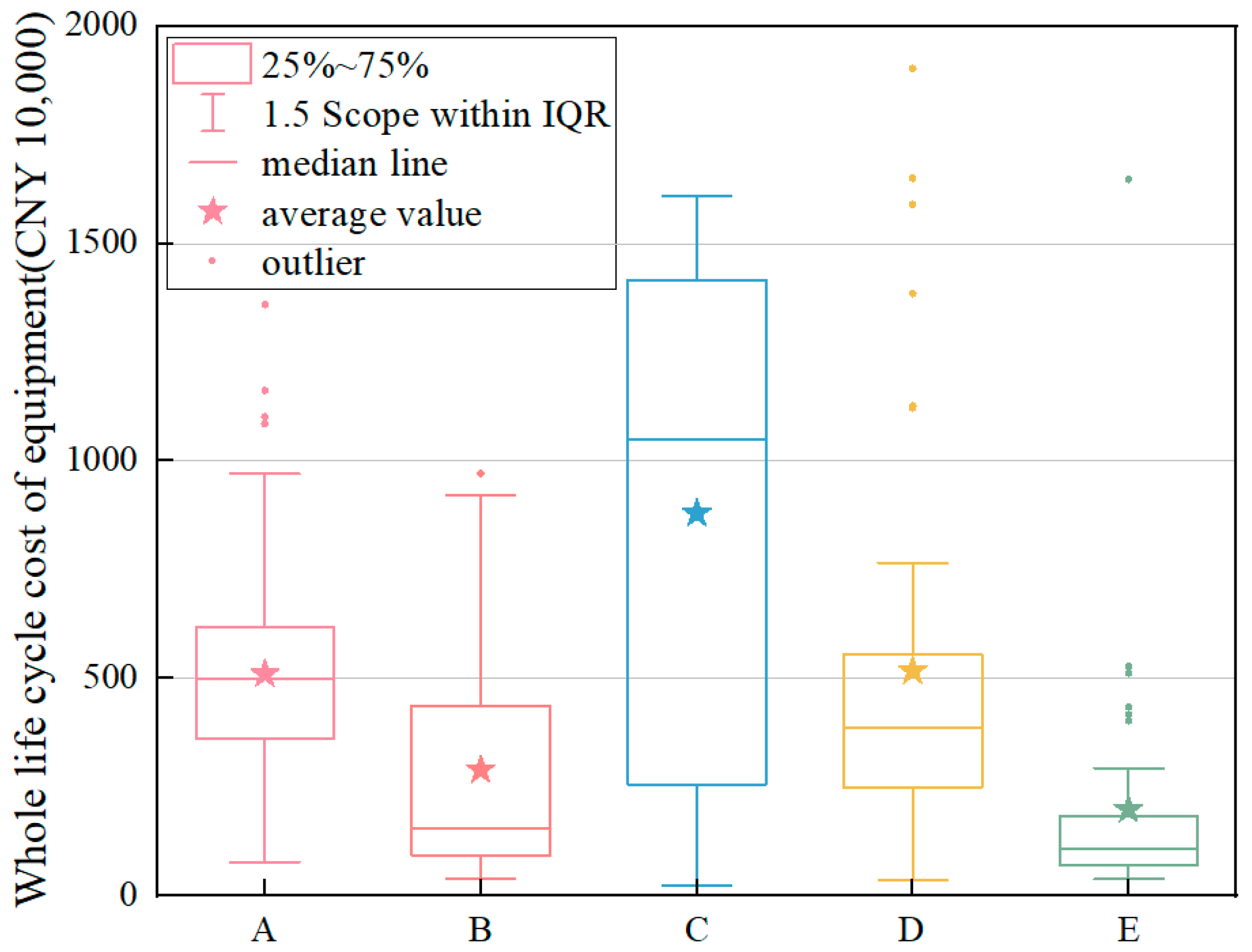
Differences in materials, manufacturing processes, production batches, lead times, transportation methods and other factors among different manufacturers can result in differences in transformer life-cycle costs [24,25]. In order to further analyze the influencing factors of the cost differences between different manufacturers, a more detailed study was carried out. Figure 3 compares the life-cycle costs of five manufacturers, and the impact of different manufacturers on the life-cycle costs can be clearly seen.
For manufacturer C, the fluctuation range of the transformer life-cycle cost reaches the maximum, fluctuating between 2,558,100 CNY and 14,165,100 CNY; the median line is located on the upper side of the mean, which is larger than the mean, the dataset has a negatively skewed distribution, and most of the life cycle cost is higher than the mean value, but the lower cost data have a more obvious effect on the overall data. For manufacturer E, the transformer life-cycle cost fluctuation range is the smallest; the box width becomes narrower, that is, the transformer life-cycle cost is more centralized; the fluctuation range is also narrowed by about 90% compared with manufacturer C, fluctuating between 699,400 CNY and 1,831,500 CNY; the median is located in the lower side of the mean, smaller than the mean; the data set exhibits a positively skewed distribution and most of the life cycle cost is lower than the mean, but the data of the lower cost have a more obvious effect on the overall data. The effect of the data is more obvious; the life-cycle cost fluctuations of the transformers of the three cooling methods of Manufacturer A, Manufacturer B and Manufacturer D range between the maximum and the minimum, in which the median lines of Manufacturer B and Manufacturer D are located on the lower side of the mean, smaller than the mean, and this dataset is positively skewed, while the median line of Manufacturer A is basically overlapping with the mean, and this dataset is normally distributed, and at this time, most of the life-cycle costs are close to the mean values, close to each other and have strong stability. In Figure 3, the transformers of Manufacturer B and Manufacturer C have fewer anomalies, larger degrees of freedom and more practical applications; the transformers of Manufacturer D have more anomalies, smaller degrees of freedom, less practical applications and the distribution is left skewed.
It can be observed through the box plots of the life-cycle cost of transformers of five different manufacturers that the life-cycle cost of the transformer of manufacturer C is the highest and that of manufacturer E is the lowest. Considering the range of fluctuation of the life-cycle cost of the transformer, the value of the life-cycle cost and the number of anomalies, it can be concluded that manufacturer B is the most suitable manufacturer, which has a lower range of fluctuation and a smaller value for the life-cycle cost of the transformer. The fluctuation range and life-cycle cost value are smaller, with stronger stability and better economy; in addition to that, its transformer has fewer anomalies, greater freedom and more practical applications. Therefore, when selecting the cooling method, it is necessary to comprehensively consider the life-cycle cost fluctuation range, life-cycle cost value and abnormal point number requirements and to make appropriate decisions according to the actual situation.

4.1.3. Cost Comparison of Transformers with Different Cooling Methods

The appropriate cooling method has a significant impact on the thermal management, power rating, reliability and life of the transformer. Choosing the appropriate cooling method ensures that the transformer operates within the safe operating temperature range and improves the performance and reliability of the equipment [20,26]. Figure 4 compares the life-cycle cost of the four cooling methods, and the impact of different cooling methods on the life-cycle cost can be clearly seen.
When the cooling method is forced oil circulation air-cooled (OFAF), the fluctuation range of the transformer life-cycle cost reaches the maximum, fluctuating between 3,086,200 CNY and 16,106,100 CNY, with the median line located on the lower side of the mean value, smaller than the mean value, and the dataset is positively skewed, with most of the full-life-cycle cost lower than the mean value, but the effect of higher cost data on the overall data are more pronounced. When the cooling method is natural cooling (ONAN), the transformer life-cycle cost fluctuation range is the smallest, and the box width becomes narrower, that is, the transformer life-cycle cost is more centralized, and the fluctuation range is about 75% narrower than OFAF, fluctuating between 1,642,300 CNY and 5,086,500 CNY; the two types of cooling methods, namely, natural oil circulating air-cooled (ONAF) and forced oil circulation directed air cooling (ODAF), exhibit transformer life-cycle cost fluctuations that range between the maximum and minimum, these methods and the ONAN median line almost coincide with the mean value; this data set is normally distributed, at this time most of the life-cycle cost is close to the mean value and it has strong stability. In Figure 4, transformers with cooling methods ONAF, ONAN and ODAF have fewer outliers, larger degrees of freedom and more practical applications; transformers with cooling method OFAF have more outliers, smaller degrees of freedom and fewer practical applications, and the distribution is left-skewed.
It can be observed from the transformer life-cycle cost boxplots for the four different cooling methods that the transformer life-cycle cost is the highest for the OFAF cooling method and the lowest for the ONAN cooling method; the main reasons for this are the following: the OFAF cooling method may require additional equipment and components, which can increase the manufacturing and material costs of the transformer, and the OFAF cooling method may also require additional space to accommodate cooling equipment such as fans or chillers, which may increase the installation and layout costs of the transformer, especially in locations with limited space. However, OFAF cooling can provide better thermal management and temperature control, which can extend the life of the transformer and improve equipment reliability. While this may increase initial investment costs, it can reduce future repair and replacement costs. Therefore, when selecting a cooling method, cost, performance, reliability and operational requirements need to be considered and appropriate decisions need to be made based on the actual situation.

4.1.4. Cost Comparison of Transformers of Different Rated Capacities

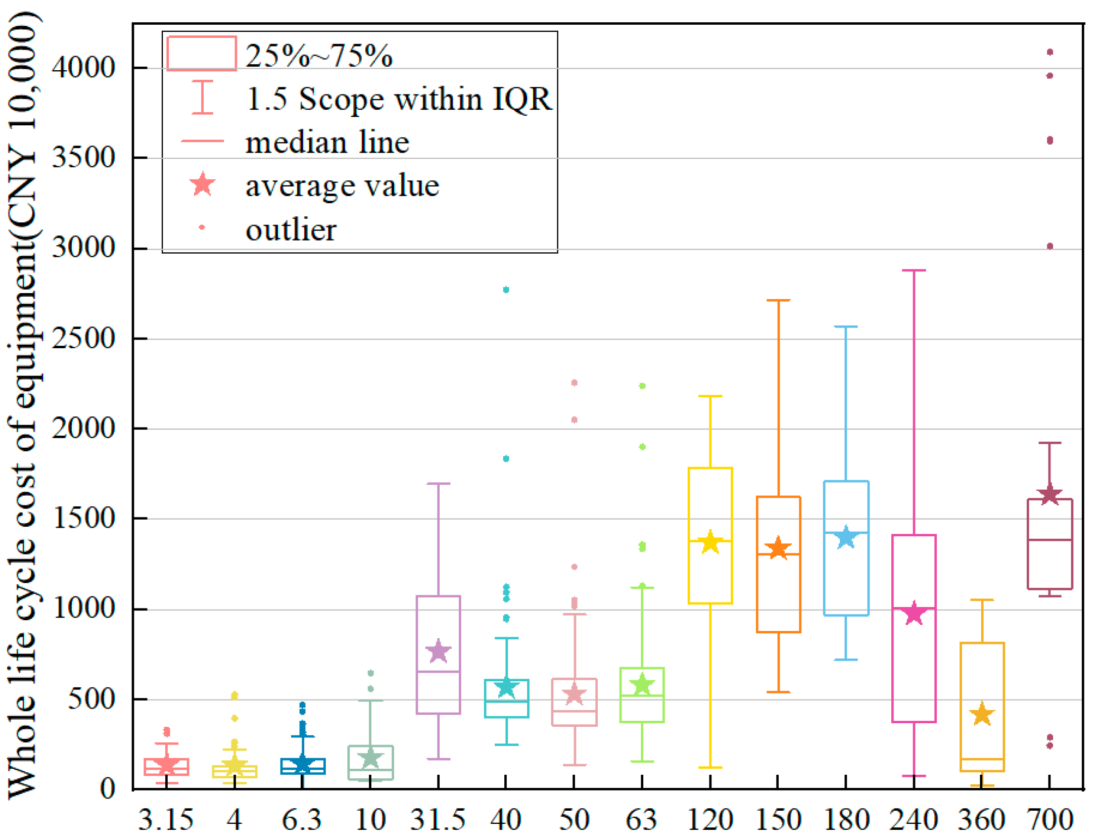
Rated capacity is the maximum power that can be continuously output as specified in the design and manufacture of the transformer. It determines the size of the transformer’s capacity, the operation and protection of the equipment and the thermal characteristics and cooling system design, as well as the economics and efficiency of the transformer [21,27]. Proper selection and configuration of the rated capacity of a transformer is a key factor in ensuring proper operation of the transformer, meeting the needs of the equipment and improving energy utilization. Figure 5 compares the life-cycle cost of 14 rated capacities, and the impact of different rated capacities on the life-cycle cost can be clearly seen.
When the rated capacity is lower than 31.5 MVA, with the increase in rated capacity, the box width of the box line diagram increases, i.e., the fluctuation of transformer life-cycle cost is increasing; when the rated capacity is equal to 31.5 MVA, the fluctuation range of the life-cycle cost of the transformer reaches the greatest value, fluctuating between 4.2271 million CNY and 10.728 million CNY; after that, the box width becomes narrower, i.e., the life-cycle cost of the transformer is more concentrated, and the fluctuation range is also about 60% narrower than that of 31.5 MVA, and the fluctuation range of the life-cycle cost of 40, 50 and 63 MVA transformers is mostly stable between 4,050,100 CNY and 4,087,200 CNY. When the rated capacity is less than or equal to 63 MVA, the median line is located at the lower side of the mean value and is smaller than the mean value, and this dataset is positively skewed; at this time, most of the life-cycle costs are below the mean, but the effect of higher costs on the overall data is more pronounced. When the rated capacity is equal to 120 MVA, the range of the life-cycle cost fluctuations for the transformer increases to 10,368,900 CNY to 17,852,600 CNY; after that, the range of life-cycle cost fluctuations for 150 and 180 MVA transformers mostly remains stable and unchanged. Only when the rated capacity is equal to 240 MVA does the range of life-cycle cost fluctuations for the transformer increase again, reaching 3,752,600 CNY to 1,400,000 CNY. It reaches between 3.7526 million CNY and 14.0989 million CNY. When the rated capacity is between 120 MVA and 240 MVA, the median line is almost overlaps with the mean value, and this data set is normally distributed, and at this time, most of the life-cycle costs are close to the mean value, which is highly stable. When the rated capacity is equal to 360 and 700 MVA, the box width is closer, roughly 7,127,800, and the median line is once again located on the lower side of the mean, smaller than the mean, and the data set is positively skewed. There are fewer anomalies in Figure 5 for 31.5, 120, 150, 180, 240 and 360 MVA transformers, which have narrower box widths, larger degrees of freedom and more practical applications; 700 MVA transformers have more anomalies, smaller degrees of freedom and fewer practical applications, and the distribution is left-skewed.
It can be observed from the box–line diagram of life-cycle cost of transformer for 14 different rated capacities that the life-cycle cost of the transformer is generally increasing with the increase in rated capacity and reaches a large value at rated capacities of 120, 150, 180 and 240 MVA, thus it can be concluded that proper selection of rated capacity helps in achieving economy and efficiency for the transformer. If the rated power is too small, the transformer may not be able to provide enough power, resulting in long-term operation of the transformer in an overloaded condition, causing equipment failure or insufficient power supply, which causes problems such as energy wastage and loss of efficiency; whereas too large a rated power may lead to over-investment and energy wastage, as the rated capacity directly affects the thermal characteristics of the transformer and the design of the cooling system, and a higher rated power means that the transformer needs to deal with greater power loss, which will generate more heat. The cooling system of the transformer needs to be able to effectively dissipate heat to ensure that the transformer maintains a normal operating temperature under the rated power, and proper thermal management is the key to ensure the long-term stable operation of the transformer. In short, when selecting the rated capacity of the transformer, it is necessary to consider factors such as cost, performance and feasibility in order to meet the actual demand and ensure economic rationality.

4.2. Linkages among the Four Influencing Factors

Figure 6 not only reflects the correlation of the four influencing factors, but also reflects the application of various parameters of the transformer in real life. From the nodes of the four influencing factors in Figure 6, it can be seen that for the transformer voltage level, the 110 kV node area is the largest and has the most practical application; with respect to the transformer manufacturer, the manufacturer B and manufacturer D node area is the largest with the most practical application; for the transformer cooling mode, the ONAN node area is the largest with the most practical application; for the rated capacity of the transformer, 31.5 MVA, 40 MVA, 50 MVA, 63 MVA and 240 MVA nodes have the largest area and the most practical applications. Next, from the flow and thickness of the lines in Figure 6, it can be concluded that 27.2% of the voltage class 110 kV transformers are produced by Manufacturer B, 68.3% of the transformers produced by Manufacturer B are cooled with ONAN and 25.4% of the transformers cooled with ONAN have a rated capacity of 31.5 MVA. In short, the 110 kV voltage class, Manufacturer B, the ONAN cooling method and the 31.5 MVA rated capacity of the transformers are the largest. In short, the 110 kV voltage level, Manufacturer B, the ONAN cooling method and 31.5 MVA rated capacity are closely related to each other, and this kind of parameterized transformer is more stable and efficient, which is widely used in actual production.

4.3. Analysis of the Proportion of Life-Cycle Costs of Transformers

According to the above analysis of the change rule of the transformer LCC under different influencing factors and the connection between the four influencing factors, a transformer of a substation in the north with a voltage level of 110 kV, from manufacturer B, with the ONAN cooling method and a rated capacity of 31.5 MVA is selected as the research object, and the main parameters of the transformer are shown in Table 1.
Based on the life-cycle cost model established in the first section of this paper, C2 operation and maintenance costs, C3 maintenance costs and C4 failure costs are combined, and in order to facilitate the visualization of the size of the share of each part of the cost of the transformer’s life cycle in the total cost of the LCC, the proportion of each cost of the LCC is obtained from the year of commissioning to the year of decommissioning, shown in Figure 7.
From Figure 7, it can be clearly seen that C1 stably occupies 98% of the LCC of this 220 kv transformer; C2 + C3 + C4 exceeds the share of C5 in the LCC in the 2nd and 17th year of commissioning; C5 exceeds the share of C2 + C3 + C4 in the LCC in the 10th and 26th years of commissioning and the difference between the shares of the two in the rest of the years is small. Therefore, when controlling the total cost of LCC, we should focus on C1, scientifically plan the initial program, efficiently manage the personnel and equipment, and minimize the expenditures on procurement, construction, financial management and labor training.

4.4. Using WOA to Optimize Transformer Life-Cycle Costs

This section uses the whale optimization algorithm and optimizes the cost of the transformer by setting the objective function. Since the optimization objective is to minimize the life-cycle cost of the transformer, the objective function can be obtained in conjunction with Section 1 as follows:
M i n { C 1 + C 2 + C 3 + C 4 + C 5 }
The actual operation of the transformer needs to meet certain reliability and economy, and the actual parameters need to meet certain objective laws. Therefore, the objective function needs to have constraints [7]:
q = 1 Q K t q × L t = L t
K t q × L t C t q
where Ktq is the Random number in (0, 1) for the substation; Ctq is the Rated capacity of the substation and Lt is the Total load of the grid.
Equation (9) states that the total load of all substations must be the same before and after optimization. Equation (10) means that the load on the transformer must not exceed its capacity.
For ease of calculation, Equation (8) is rewritten in the following form in conjunction with Section 1:
M i n { C 1 + C t e + C t o l m + C 4 + C 5 }
C t e = C N L L + C L L
C N L L = a × P 0 × T
C L L = a × P K × T × K 2
where Cte is the transformer energy cost; Ctolm is the transformer operation labor maintenance cost; CNLL is the cost of no-load loss; CLL is the cost of load loss; a is the level of tariff, generally take 0.47~0.5 CNY/kWh; P0 is the no-load loss, selected in this paper 3.2 of the 110 kV transformer parameters, 63.4 kW; Pk is the load loss, selected in the same way as the P0, for the 285 kW; T is the annual operating hours, take 8760 and K is the load factor.
For computational convenience, all parameters except K are defined as constants to obtain a single-objective optimization function with load factor K as the independent variable. Table 2 lists the average values of the LCC for 30 years of transformer operation at a substation in the north selected in 3.2 of this paper. Since the transformer energy cost Cte is relatively small compared to the transformer operation labor and maintenance cost Ctolm, from Section 1, the failure cost C4 and maintenance cost C3 are combined and counted; C2 + C3 + C4 can be approximated as Ctolm.
Substituting all the above values into Equation (11), the simplified objective function is obtained as follows:
M i n { 621.95 + 119.84 × K 2 }
Next, the objective function was optimized using MATLAB software, employing the whale optimization algorithm.
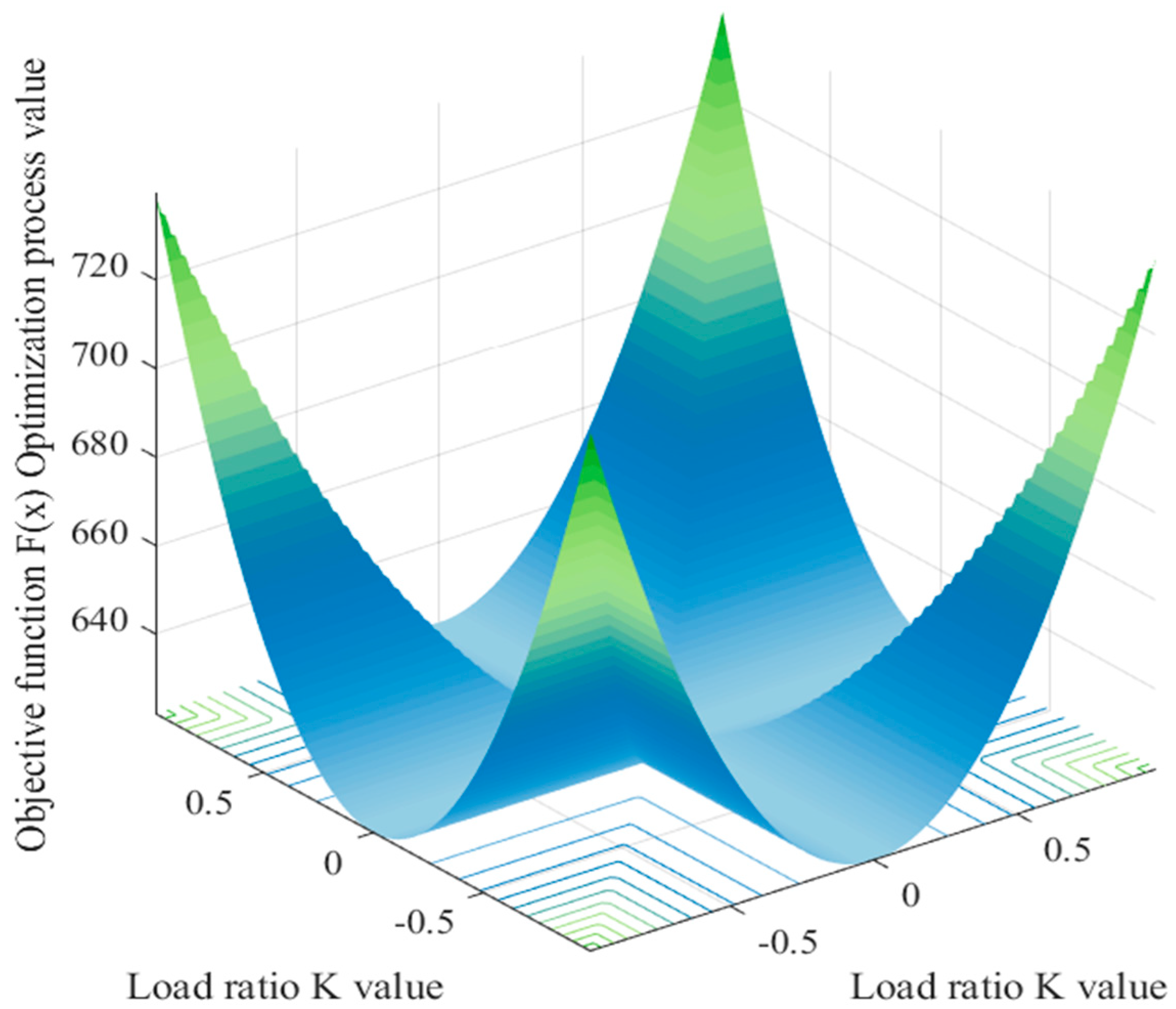
By setting y = x, a graph of the spatial 3D transformer LCC function can be obtained in order to observe the optimization seeking process of WOA more clearly, as in Figure 8. It can be discovered that the objective function is a single-peak function with only one global optimum, which demonstrates the stronger competitiveness and exploitation of WOA when compared to other meta-heuristic algorithms. WOA is also the most efficient optimizer, or at least the second-best optimizer, for this function in terms of the smoothness of the picture. Therefore, WOA can provide a very good optimization path for transformer LCC optimization.
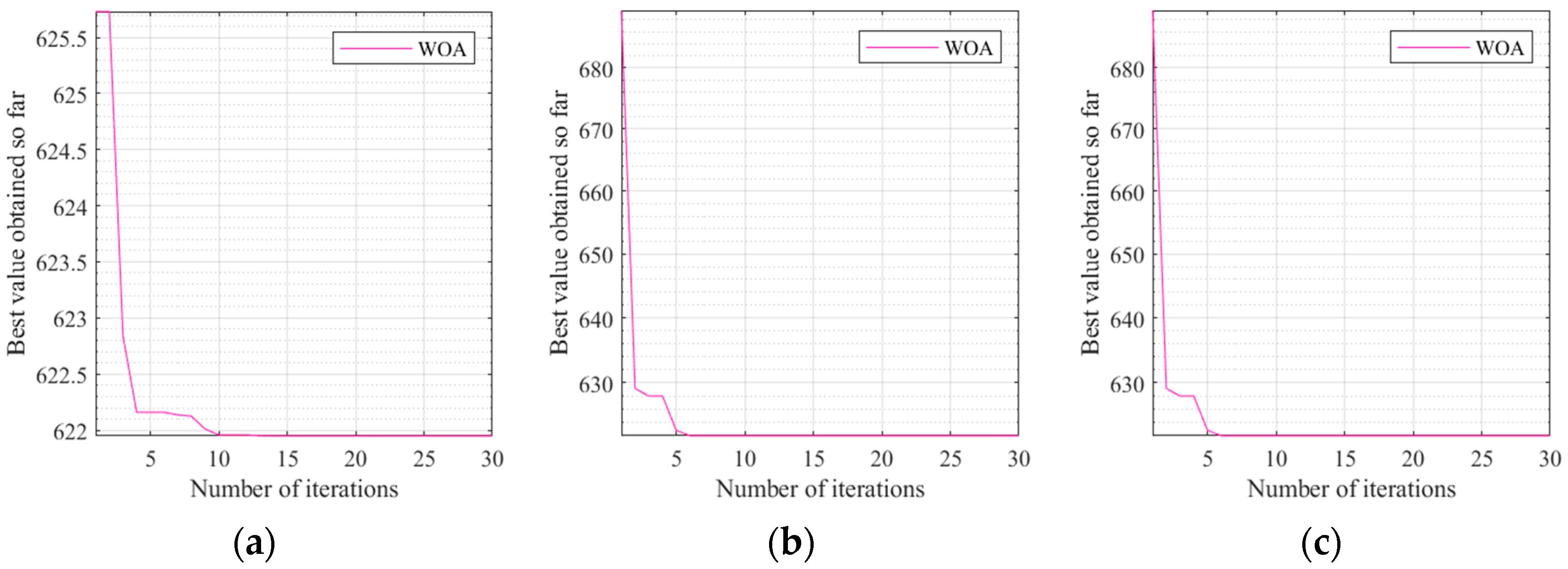
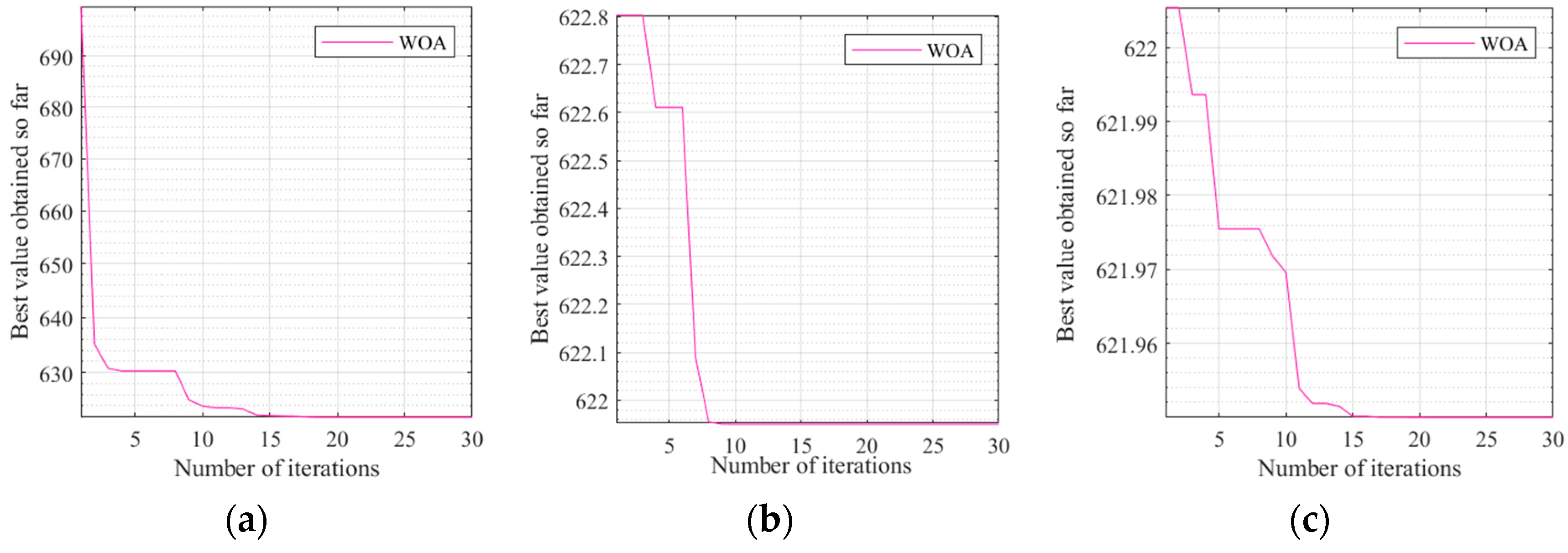
However, throughout the calculations, it was found that different population sizes and number of iterations produce different objective function optimization curves; therefore, transformer LCCs were calculated for population sizes of 10, 20 and 30 with a number of iterations of 10, 30 and 50, respectively. The results are as follows (Table 3):
In Figure 9a–c are the optimization curves of the objective function for different number of iterations when the population size is 10.
In Figure 10a–c are the optimization curves of the objective function for different number of iterations when the population size is 20.
In Figure 11a–c are the optimization curves of the objective function for different number of iterations when the population size is 30.
From the above graph, we can see the following:
  • Under the same number of iterations, the smaller the population number, the smoother the optimization curve; this is because the smaller population converges faster and the easier it is to enter the local optimal solution. On the contrary, the larger the population, the slower the convergence of the calculation, because with the expansion of the population the probability of wanting to cover all the solutions in the selection is decreasing, which can easily lead to the invalidation of the calculation, so generally the size of the problem that can be used in the population algorithm is not too large [28];
  • Under the same number of populations, the more the number of iterations, the smoother the optimization curve. This is because the objective function has not completely reached stability and basic convergence. The larger the number of iterations, the higher the accuracy and the smoother the curve that is obtained, but if the objective function has reached stability and basic convergence, the number of iterations to accumulate the computational error is also very large [29]. This paper lists the three different iteration times as within a reasonable range, so there is a law of the above;
  • When the number of populations is 10 and 30, with the number of iterations, the number of generations in which the optimal value occurs varies more. When the population size is 20, the number of generations with optimal values remains at a stable level with little change.
Therefore, the objective function optimization curve with a population size of 20 and an iteration number of 50 is the best optimization curve for the transformer LCC in this algorithm, and the optimal optimization value is 6,219,510,000 CNY. This objective function optimization cost saves nearly 0.1% compared to the transformer optimization cost with a population size of 10. Meanwhile, compared to the transformer optimization cost with a population size of 30, this objective function optimization curve is more stable in terms of convergence and number of generations of optimal values appearing, so that a more accurate optimal value can be obtained.
By selecting a 220 kV transformer and optimizing it with the whale algorithm, a solution close to the optimal solution can be found in a short time. For the optimization problems of transformers of other voltage levels, WOA can still be adapted to different voltage levels to find the optimal solution, and WOA can be used to solve transformer optimization related problems, both in the design of power systems and in other engineering fields. In conclusion, WOA has the advantages of high efficiency, flexibility and versatility and can be used to effectively optimize transformers of different voltage levels, which can be used to find the optimal transformer LCC in practical applications to reduce the cost of the transformer and to improve the efficiency of energy use.

5. Conclusions

  • This paper analyzes the cost law under different influencing factors involved in the transformer during its service life. Through the processing of a large number of grid transformer life-cycle cost data, under different influencing factors of the transformer LCC fluctuation range, mean value and normal curve distribution characteristics can be obtained and the following law can be stated: 110 kV voltage level, B manufacturers, ONAN cooling mode and 31.5 MVA Rated capacity are closely linked, this parameter collocation of the transformer use process is more stable and efficient and is widely used in actual production. Compared with the previous research, this paper combed the transformer LCC data under different influencing factors, drew charts to more intuitively show the above law and analyzed and summarized the connection between the four influencing factors, which makes up for the lack of previous literature on the study of the influencing factors of transformer LCC, and has a certain guiding role in the selection of transformers for practical application;
  • In addition to this, based on the transformer LCC model established in the first section of this paper, the LCC proportion of each type of cost from commissioning to decommissioning of the transformer was calculated using specific arithmetic examples, setting various parameters such as the rated capacity, voltage class and cooling method of the transformer as quantitative variables and considering only the impact of each part of the cost on the total cost, thus obtaining the following: C1 stably occupies 98% of the life cycle cost of the selected 220 kv transformer during the commissioning period. Therefore, when selecting a transformer, we should focus on the C1 of the selected transformer, scientifically plan the initial program, efficiently manage the personnel and equipment and minimize the expenditures in procurement and construction, financial management and labor training. Compared with previous studies, this paper sets other influencing factors as quantitative, focuses on the impact of C1C5 on the total cost and more scientifically and rationally proves the important impact of C1 on transformer LCC, which is of great significance to help enterprises make smarter decisions in the process of practical application and to reduce energy consumption and costs;
  • After that, based on the transformer LCC model established in the first section of this paper, the objective function is constructed for the specific arithmetic example of 3.2, and all the parameters except the loading rate K are defined as constants so as to obtain an objective optimization function with K as the independent variable. By setting y = x, a spatial 3D transformer LCC function plot is obtained, and the optimization seeking process of the whale optimization algorithm can be clearly observed: the objective function is a single-peak function with only one global optimum, and the WOA is also the most effective optimizer for this function in terms of the smoothness of the surface. Meanwhile, in the whole optimization calculation process, it can be concluded that under the same number of iterations, the smaller the population number, the smoother the optimization curve is; under the same number of populations, the larger the number of iterations, the smoother the optimization curve is; when the population number is 20, the number of generations of optimal values appearing maintains at a stable level without much change. Therefore, the objective function optimization curve when the population number is 20 and 50 iterations is the best optimization curve for the transformer LCC in this algorithm, and the optimal optimization value is 6,219,510,000 CNY. Compared with previous studies, this algorithm example shows that the whale optimization algorithm is very competitive and exploitable, and the principle of WOA is relatively intuitive and easy to understand, which helps to better explain and convey the optimization results in practical applications, and it can provide a very good optimization path for transformer LCC optimization, and it also proves that choosing a smaller number of populations and a larger number of iterations in the optimization process can make the optimization results more accurate and reliable, which provides a reliable basis and reference for the optimization of transformer LCC in practical applications. Procurement management is a management activity for procurement work. Through procurement management, the modernized management mode of the power grid company can be implemented; guaranteeing the improvement of the management level, procurement management can effectively reduce the procurement cost and prevent the procurement risk. In the future, we can combine the results of life-cycle cost optimization with the procurement management system of the power grid, analyze the change characteristics of procurement management under the concept of life-cycle management, adopt the methods of segment assignment and quantification, fuzzy comprehensive evaluation, etc., and study the differences in the requirements of procurement in various aspects such as power grid planning, engineering and construction, operation and maintenance, asset handling, etc., so as to provide a high-quality material guarantee for the construction of a strong and intelligent power grid.

Author Contributions

Conceptualization, F.G. and H.C.; methodology, F.G. and P.P.; software, F.G.; validation, F.G., X.Z. and X.J.; formal analysis, F.G. and P.P.; investigation, F.G. and H.C.; resources, F.G. and C.X.; data curation, F.G. and X.Z.; writing—original draft preparation, F.G.; writing—review and editing, F.G.; visualization, F.G.; supervision, F.G.; project administration, F.G. and X.J.; funding acquisition, C.X. All authors have read and agreed to the published version of the manuscript.

Funding

This work was supported by the Science and Technology Project of the State Grid Corporation of China (No. 5200-202356133A-1-1-ZN). Introduction to Fund Projects: Application units: State Grid Corporation of China, North China Electric Power University. Project Name: Research on Key Technologies for Optimal Selection and Cost Stability Control of Transmission and Transformation Engineering Schemes under Unified Large Market and Carbon Reduction Development.

Data Availability Statement

Data is contained within the article.

Conflicts of Interest

Author Cheng Xin was employed by the company State Grid Economic and Technical Research Institute Co. Author Xue Jiang was employed by the company Economic and Technical Research Institute of State Grid Liaoning Electric Power Co. The remaining authors declare that the research was conducted in the absence of any commercial or financial relationships that could be construed as a potential conflict of interest.

Nomenclature

aTariff levelECPE-commerce platform
AFAvailability factorERPEnterprise resource planning
AISAir Insulated SubstationEUACEquivalent uniform annual costs
C1Initial investment cost (CNY 10,000)GISGas Insulated Substation
C2Maintenance cost (CNY 10,000)HGISHybrid Gas Insulated Substation
C3Overhaul cost (CNY 10,000)IQRInterquartile range
C4Failure cost (CNY 10,000)KLoad factor
C5Decommissioning disposal cost (CNY 10,000)KtqRandom number in (0, 1) for the substation
CcCommissioning cost (CNY 10,000)LtTotal load of the grid (kW)
CcuCompensation for critical users (CNY 10,000)LCCLife-cycle cost
CerCost of emergency repairs (CNY 10,000)ODAFForced oil circulation directed air cooling
CfFinance cost (CNY 10,000)OFAFForced oil circulation air-cooled
CiInstallation cost (CNY 10,000)ONAFNatural oil circulating air-cooled
CLLCost of lost load (CNY 10,000)ONANNatural cooling
CNLLCost of no-load loss (CNY 10,000)P0No-load losses (kW)
CNSCost of the recovered salvage value (CNY 10,000)PkLoad losses (kW)
ComTransformer operation labor maintenance costs (CNY 10,000)PMSPower production management system
Com(t)Operation and maintenance cost of the equipment in year t (CNY 10,000)Q11st quartile
CpcProcurement and construction cost (CNY 10,000)Q22nd quartile
CRCleanup cost of the transformer at end-of-life (CNY 10,000)Q33rd quartile
CtTraining cost (CNY 10,000)rInflation rate
CteTransformer energy cost (CNY 10,000)RSocial discount rate
CtolmTransformer operation labor maintenance cost (CNY 10,000)TNumber of hours of annual operation (hour)
CtqRated capacity of the substation (CNY 10,000)WOAWhale optimization algorithm
CVCost of the lost value of the transformer at early end-of-life (CNY 10,000)εExpected salvage value rate

References

  1. Hussain Sheikh, A.; Ilahi Bakhsh, F. Sustainable development and applications of variable frequency transformer (VFT). Sustain. Energy Technol. Assess. 2023, 57, 103193. [Google Scholar] [CrossRef]
  2. Zhou, C.; Che, C.; Wang, P.; Zhang, Q. Diformer: A dynamic self-differential transformer for new energy power autoregressive prediction. Knowl. Based Syst. 2023, 281, 111061. [Google Scholar] [CrossRef]
  3. Yuqin, X.; Zheng, R. Modeling and Comprehensive Sensitivity Analysis of Life Cycle Cost of Power Transformers. J. North China Electr. Power Univ. 2014, 41, 80–87. (In Chinese) [Google Scholar]
  4. Du, M.; Zhao, Y.; Liu, C.; Zhu, Z. Lifecycle cost forecast of 110 kV power transformers based on support vector regression and gray wolf optimization. Alex. Eng. J. 2021, 60, 5393–5399. [Google Scholar] [CrossRef]
  5. Safaei, F.; Niasati, M. Calculation of UHV transformer insulation risk by extended Monte Carlo method. Electr. Power Syst. Res. 2023, 218, 109219. [Google Scholar] [CrossRef]
  6. Toren, M. Optimization of transformer parameters at distribution and power levels with hybrid Grey wolf-whale optimization algorithm. Eng. Sci. Technol. Int. J. 2023, 43, 101439. [Google Scholar] [CrossRef]
  7. Hosseinkhanloo, M.; Kalantari, N.T.; Behjat, V.; Ravadanegh, S.N. Optimal exploitation of power transformer fleet considering loss of life and economic evaluation based on failure probability. Electr. Power Syst. Res. 2022, 213, 108801. [Google Scholar] [CrossRef]
  8. Marchi, B.; Zanoni, S.; Mazzoldi, L.; Reboldi, R. Energy Efficient EAF Transformer—A Holistic Life Cycle Cost Approach. Procedia CIRP 2016, 48, 319–324. [Google Scholar] [CrossRef]
  9. Han, X.; Li, Y.; Nie, L.; Huang, X.; Deng, Y.; Yan, J.; Kourkoumpas, D.; Karellas, S. Comparative life cycle greenhouse gas emissions assessment of battery energy storage technologies for grid applications. J. Clean Prod. 2023, 392, 136251. [Google Scholar] [CrossRef]
  10. Park, S.H.; Jang, K.W.; Kweon, D.J.; Shon, J.G. Analysis of Economic Replacement Cycle of Power Transformer Based on LCC Considering Maintenance Effect. J. Electr. Eng. Technol. 2018, 13, 1630–1636. [Google Scholar]
  11. Chengjun, X.; Guihua, Q. Life Cycle Cost Model and Sensitivity Analysis of Power Transformers. East China Electr. Power 2012, 40, 26–30. (In Chinese) [Google Scholar]
  12. Jie, L. Research on Power Transformer Selection Based on Life Cycle Cost; North China Electric Power University: Beijing, China, 2016. (In Chinese) [Google Scholar]
  13. Xiubo, J.; Wenxuan, W. Application of Interval Analysis Method in the Life Cycle Cost Model of Power Transformers. Electr. Power Autom. Equip. 2011, 31, 50–53. (In Chinese) [Google Scholar]
  14. Dong, S.; Zhongneng, M. Life cycle cost model and Sensitivity analysis of distribution network switchgear. Power Syst. Prot. Control. 2018, 46, 150–155. (In Chinese) [Google Scholar]
  15. Mohan, T.M.; Nireekshana, T. A Genetic Algorithm for Solving Optimal Power Flow Problem. In Proceedings of the 2019 3rd International Conference on Electronics, Communication and Aerospace Technology (ICECA), Coimbatore, India, 12–14 June 2019; pp. 1438–1440. [Google Scholar]
  16. Awais, M.; Basit, A.; Adnan, R.; Khan, Z.A.; Qasim, U.; Shafique, T.; Javaid, N. Overload Management in Transmission System Using Particle Swarm Optimization. Procedia Comput. Sci. 2015, 52, 858–865. [Google Scholar] [CrossRef]
  17. Atashpaz-Gargari, E.; Lucas, C. Imperialist Competitive Algorithm: An Algorithm for Optimization Inspired by Imperialistic Competition. In Proceedings of the 2007 IEEE Congress on Evolutionary Computation, Singapore, 25–28 September 2007; pp. 4661–4667. [Google Scholar]
  18. Mirjalili, S.; Lewis, A. The Whale Optimization Algorithm. Adv. Eng. Softw. 2016, 95, 51–67. [Google Scholar] [CrossRef]
  19. Albrechtowicz, P.; Cisek, P. An impact of the line resistance on the power flow calculations with installed phase-shifting transformer in different voltage levels power systems. Electr. Power Syst. Res. 2022, 209, 107970. [Google Scholar] [CrossRef]
  20. Bengang, W.; Hua, H.; Junshang, L.; Nannan, W.; Mingqiu, D.; Tianyi, J. Three Dimensional Simulation Technology Research of Split Type Cooling Transformer Based on Finite Volume Method. Energy Procedia 2017, 141, 405–410. [Google Scholar] [CrossRef]
  21. Li, C.; Zhang, H.; Zhou, H.; Sun, D.; Dong, Z.; Li, J. Double-layer optimized configuration of distributed energy storage and transformer capacity in distribution network. Int. J. Electr. Power 2023, 147, 108834. [Google Scholar] [CrossRef]
  22. Gustavsen, B.; Portillo, A.; Ronchi, R.; Mjelve, A. Measurements for validation of manufacturer’s white-box transformer models. Procedia Eng. 2017, 202, 240–250. [Google Scholar] [CrossRef]
  23. Szczerba, Z.; Siodelski, A.; Grzenkowicz, A. The Problems of Transformer Automatic Control for Voltage Levels and Reactive Power Flow Regulation in Electrical Power System. IFAC Proc. Vol. 1997, 30, 55–61. [Google Scholar] [CrossRef]
  24. Chien, C.; Trappey, A.J.C.; Wang, C. ARIMA-AdaBoost hybrid approach for product quality prediction in advanced transformer manufacturing. Adv. Eng. Inf. 2023, 57, 102055. [Google Scholar] [CrossRef]
  25. Yang, Z.; Shang, W.; Zhang, H.; Garg, H.; Han, C. Assessing the green distribution transformer manufacturing process using a cloud-based q-rung orthopair fuzzy multi-criteria framework. Appl. Energ 2022, 311, 118687. [Google Scholar] [CrossRef]
  26. Ajour, M.N.; Abu-Hamdeh, N.H.; Mostafa, M.E. Optimizing and simulating cooling of electric transformer room utilizing genetic algorithm to reduce electricity/water demand by incorporating borehole ground heat exchangers. J. Taiwan Inst. Chem. Eng. 2023, 148, 104907. [Google Scholar] [CrossRef]
  27. Niu, B.; Wu, X.; Yu, J.; Wu, H.; Liu, W. Research on large-capacity impulse test technology for distribution transformer based on energy storage intelligent power. Energy Rep. 2022, 8, 275–285. [Google Scholar] [CrossRef]
  28. Chauhdry, M.H.M. A framework using nested partitions algorithm for convergence analysis of population distribution-based methods. Eur. J. Comput. Optim. 2023, 11, 100067. [Google Scholar] [CrossRef]
  29. Aarnoudse, L.; Pavlov, A.; Oomen, T. Nonlinear Iterative Learning Control: A Frequency-Domain Approach for Fast Convergence and High Accuracy. IFAC Pap. 2023, 56, 1889–1894. [Google Scholar] [CrossRef]
Figure 1. Flowchart of whale optimization algorithm.
Energies 17 00606 g001
Figure 2. Comparison of life-cycle costs for 5 voltage levels.
Energies 17 00606 g002
Figure 3. Comparison of total life-cycle costs for 5 Manufacturers.
Energies 17 00606 g003
Figure 4. Comparison of life-cycle cost of 4 cooling methods.
Energies 17 00606 g004
Figure 5. Life-cycle cost comparison chart for 14 rated capacities.
Energies 17 00606 g005
Figure 6. Schematic diagram reflecting the correlation of the four influencing factors and the application of the various parameters of the transformer.
Energies 17 00606 g006
Figure 7. The proportion of each part of the cost to the total life-cycle cost from the year of operation to the year of retirement.
Energies 17 00606 g007
Figure 8. 3D Diagram of transformer life-cycle cost function.
Energies 17 00606 g008
Figure 9. Optimization curves of the objective function with different number of iterations for a population size of 10. Where (a) the number of iterations is 10; (b) the number of iterations is 30 and (c) the number of iterations is 50.
Energies 17 00606 g009
Figure 10. Optimization curves of the objective function with different number of iterations for a population size of 20. Where (a) the number of iterations is 10; (b) the number of iterations is 30 and (c) the number of iterations is 50.
Energies 17 00606 g010
Figure 11. Optimization curves of the objective function with different number of iterations for a population size of 30. Where (a) the number of iterations is 10; (b) the number of iterations is 30 and (c) the number of iterations is 50.
Energies 17 00606 g011
Table 1. The main parameters of a substation transformer in the north.
ParametersValue
equipment typemain transformer
affiliated substation110 kV Substation
Wiring Methoddouble busbar 1
voltage levelAC 110 kV
date of commissioning1992.03
commissioning period30
rated capacity (MVA)31.5
GIS, AIS, HGISAIS 2
indoor, semi-indoor, outdooroutdoor
whether there is intelligent substationYes
arrangementabove ground outdoor
degree of dirtinessClass c 3
topographic conditionpeacefully
phasethree-phase
dielectricoil-dip
winding formtriple winding 4
wooling methodONAN
intervalsmain transformer interval 5
rated voltage110
rated current472.4
no-load loss (kW)63.4
load Loss (kW)285
1 The double busbar wiring where one set is the working bus and one set is the standby bus and is operated in parallel via busbar circuit breakers. 2 The Air Insulated Substation is the use of insulating devices (ceramic sleeve as the equipment shell and external insulation), the charged part, the grounded part of the separation of a certain distance, relying on air insulation. 3 The degree of dirtiness is divided into five classes from low to high: a, b, c, d and e. Class c is the medium degree of dirtiness. 4 The triple-winding transformer has three windings per phase, and when one winding is connected to the AC supply the other two windings induce different potentials. 5 The main transformer interval is the interval where the high and low voltage sides of the main transformer are connected to the busbar to realize the conversion between high voltage and low voltage.
Table 2. Average LCC value of a 110 kV transformer after 30 years of operation.
CostC1:C2 + C3 + C4
(Approximated as Ctolm)
C5
Average
(CNY 10,000)
609.0120.94−34.66
Table 3. Objective function optimization results.
Population SizeNumber of IterationsGeneration in Which the Optimal Value AppearsBest Value (CNY 10,000)
10106620.982
3014621.243
5019621.947
201010621.943
3011621.945
5013621.951
30107621.944
3016621.946
5021621.949
Disclaimer/Publisher’s Note: The statements, opinions and data contained in all publications are solely those of the individual author(s) and contributor(s) and not of MDPI and/or the editor(s). MDPI and/or the editor(s) disclaim responsibility for any injury to people or property resulting from any ideas, methods, instructions or products referred to in the content.