Article

Increasing the Efficiency of Loading Devices for Biomass Boilers

1
Department of Thermal Engineering and Energy Technology, Dnipro University of Technology, 49005 Dnipro, Ukraine
2
Power Supply Department, National Technical University of Ukraine “Igor Sikorsky Kyiv Polytechnic Institute”, 03056 Kyiv, Ukraine
3
Department of Microbiology, Virology and Biotechnology, Oles Honchar Dnipro National University, 49010 Dnipro, Ukraine
4
International Institute for Applied Systems Analysis, A-2361 Laxenburg, Austria
5
Green Technology Research Center, Yuan Ze University, Taoyuan 320, Taiwan
6
Department for the Forecasting of Power Sector Development, General Energy Institute of the NAS of Ukraine, 03150 Kyiv, Ukraine
7
Department of Theoretical Electrical Engineering, Institute of Electrodynamics of the NAS of Ukraine, 03057 Kyiv, Ukraine
*
Author to whom correspondence should be addressed.
Energies 2024, 17(3), 590; https://doi.org/10.3390/en17030590
Submission received: 13 November 2023 / Revised: 17 December 2023 / Accepted: 22 December 2023 / Published: 25 January 2024
(This article belongs to the Section A4: Bio-Energy)

Abstract

:
The article examines a method of loading biomass waste into a boiler unit, which ensures the gas tightness of the boiler’s working chamber by forming a “plug” of biomass as it moves through the cylindrical channel of the screw feeder. Local biomass wastes (sunflower husks, coniferous wood sawdust, and walnut shells) were selected for the study, a distinctive feature of which is that they did not undergo any prior processing before use (drying, fractionation, grinding, etc.). The properties of biomass as a bulk material (angle of internal friction) were determined experimentally. According to the results, sawdust from coniferous wood has an average angle of internal friction that is 1.48 times bigger than that of sunflower husks and 1.29 times bigger than walnut shells, while the average loading mass of sawdust is 2.2 times less than that of sunflower husks and 2.6 times less than that of walnut shells. This low bulk density and high angle of internal friction for sawdust suggest the likelihood of spontaneous compaction and layer suspension. Experimental studies were also conducted on the compaction force of the biomass layer. It was found that neither coniferous wood sawdust nor walnut shells can be used in the proposed feeder because the sawdust forms a dense layer that does not disperse under any compaction, and the walnut shells do not form a “plug” in the studied pressure range. Therefore, only sunflower husks were used for further studies. The empirical dependence of the density of the sunflower husk layer on the compaction pressure was obtained from the results. It was determined that to ensure a suction level through a screw feeder with a diameter of 0.1 ÷ 0.25 m into the furnace of the boiler unit of no more than 0.1 m3/h with a pressure difference between the boiler furnace and the surrounding environment ΔP = 0.05 ÷ 0.3 kPa, the relative increase in the density of the “plug” from sunflower husks should not exceed the bulk density of the uncompacted layer by more than 11.5%. Experimentally, it was determined that the geometric dimensions of the “plug” from sunflower husk, which ensure the necessary level of gas tightness of the feeder, depend only on the diameter of the channel and are 1.136·d. Calculations were made to obtain the dependencies of the compaction force of the biomass waste layer on the level of suction (in the studied range Q = 0.01 ÷ 0.1 m3/h) into the furnace of the boiler unit under controlled pressure drops (in the studied range ΔP = 0.05 ÷ 0.3 kPa) between the boiler furnace and the surrounding environment for feeders with different screw diameters (d = 0.1 ÷ 0.25 m), which can be used for the practical determination of the geometric and operational parameters of the screw feeder when operating a boiler unit on sunflower husks.

1. Introduction

Today’s difficult situation in the global energy market requires the continuous development of technologies in the usage of renewable fuels, the main requirements for which are energy, environmental, and economic efficiency. One of the available renewable energy sources is biomass, both in the form of primary wood and in the form of wood and agriculture processing waste (chips, sawdust, straw, sunflower and buckwheat husks, walnut shells, etc.). According to a Status Report [1], the value of all biofuels to the economy has a EUR 2.3 billion direct contribution impact on the EU GDP and provides 250,000 direct and indirect jobs along the value chain. Among them, 29% of innovative companies are based in the EU, behind the US and Japan. Research by The International Renewable Energy Agency (IRENA) [2] has shown that solid biomass from forests, farms, and cities is a major source of heat and power, which could provide one-fifth of the energy the world will consume in 2050.
Biomass as a fuel has the following advantages: it is widely distributed and in significant volumes, has large energy potential, can be renewed relatively quickly, can be used in its original form with existing energy equipment, and is also easily recyclable in other fuels. In addition, the harmful effects of biomass are minimal—the amount of greenhouse gases released while burning this fuel is equal to the amount of CO2 absorbed during its growth. Since there is no increase in the concentration of greenhouse gases in the atmosphere, biomass is considered a CO2-neutral fuel [3,4,5]. Furthermore, finely dispersed biomass in the form of waste is a by-product of the main production and therefore has a relatively low cost. The main disadvantages of such biomass include the low bulk density and a large number of volatile particles uneven in size and shape. The properties of various types of biomass waste have been investigated by many scientists in Ukraine [6,7,8,9] and abroad [10,11,12], but due to the large number of types of biomass suitable for energy use and the development of new technologies, projects are being carried out with the aim to improve the research area.
There is a large number of technologies for the energy-efficient use of biomass: combustion, gasification, pyrolysis, anaerobic fermentation, etc. The most common method is the direct combustion of biomass and its wastes in the furnaces of boiler units for heat and electricity. For example, currently in Ukraine, there are up to 20 CHPPs and thermal power plants that function on wood chips and sunflower husks; projects of another 30 power plants are at different stages of development, from the idea to the project design [1,6,13,14]. Depending on the type of boiler, it is possible to burn biomass of various sizes (firewood, briquettes, pellets, sawdust, and agricultural waste) and in different ways (burning in a dense layer, boiling layer, ingrown burning, etc.). For example, in previous studies [15,16], it is noted that the most suitable among the four types of biomass considered (sunflower husk, rapeseed cake, corn straw, and willow) in terms of energy and environmental indicators for use in domestic fuel boilers with a capacity of 10 kW are fuel pellets (pellets) made from sunflower husks and willow. There are also some studies on the possibility of maintaining the air excess coefficient in boiler units of small and medium power [17,18].
A necessary requirement for the work of a finely dispersed biomass solid fuel boiler is the sealing of the boiler working space, which prevents air suction when working under discharge, so the device for loading fuel into the boiler is one of the main components that determines both the efficiency of the entire boiler installation and its safety.
There are several types of biomass boiler-loading devices used to deliver biomass fuel into the combustion chamber. The most common types of biomass boiler loading devices are described below [2,6,12,19].
Screw auger feeders use a rotating screw mechanism to transport biomass fuel from a storage hopper to the combustion chamber. They are suitable for a wide range of biomass materials, including wood pellets, wood chips, and agricultural residues [20,21]. Chain grate feeders consist of a moving chain that transports biomass fuel across the combustion chamber. This type of loading device is often used for biomass boilers designed for larger and bulkier fuel types like wood chips or agricultural residues [21]. Rotary valve feeders use a rotating mechanism with chambers to control the flow of biomass fuel into the combustion chamber. They provide precise control over the feed rate and are commonly used in automated systems [20,21]. Gravity feed systems rely on the force of gravity to move biomass fuel from a higher storage area to the combustion chamber. They can be simple and cost-effective for certain applications [20,21].
The choice of loading device depends on factors such as the type of biomass fuel being used, the boiler design, and the desired level of automation.
Loading devices play a crucial role in delivering biomass fuel into the combustion chamber, ensuring proper combustion and energy generation. In this regard, improving the work of the feeder for finely dispersed biomass is relevant not only for Ukraine but also for many countries in the world [21,22,23,24]. To enhance the efficiency of biomass boiler loading devices, several strategies are used. First, the implementation of advanced automation and control systems regulates the loading process based on real-time data, such as the boiler’s temperature, combustion efficiency, and fuel moisture content. This ensures optimal fuel delivery and combustion [19,21]. Second, the integration of sensors to monitor parameters like biomass level, moisture content, and combustion performance is used. Feedback from these sensors can be used to adjust loading rates and optimize the combustion process [16]. Furthermore, using variable speed drives for the loading mechanisms allows for better control over the fuel feed rate, adapting to the boiler’s requirements and reducing overloading or underloading issues [17,25]. Moreover, using pre-processing for the biomass to achieve a uniform size and moisture content makes the fuel flow more consistent and predictable, improving the loading process [2,21]. In addition, routine maintenance (cleaning, lubrication, and inspection) for the loading device and associated components can prevent mechanical failures and ensure consistent performance [22]. Lastly, regular assessment of the loading device’s performance and seeking opportunities for improvement of its loading efficiency are necessary [21].
The optimal strategy for improvement of the efficiency of biomass boiler loading devices depends on the specific design and requirements of a biomass boiler system.
It is known from previous studies that when loading into the working chamber of the boiler unit of finely dispersed material, a consequent installation of two feeders was previously traditional: drum and screw [20,22,25]. Another option was the installation of intermediate tanks—bunkers. Such a solution regarding biomass waste, with low bulk density and a tendency to suspend the layer, requires the installation of additional mechanical devices (vibrators, screws, etc.), which increase capital costs and complicate the operation of the entire energy complex [22].
According to previous studies [26], another property of fine biomass is its ability to compact when being pushed through a channel. Such a method is widely used, for example, in the briquetting of waste. This property lays the basis for the work of screw feeders with an elongated tail channel (sometimes narrowing), in which a layer of material compacted due to friction forces is formed [21]. The disadvantage of such a device is that for each individual technological unit and type of fuel, it is necessary to perform separate calculations.
In this publication, the method of loading is considered, which ensures the gas density of the working chamber of the unit by the formation of a “cork” of finely dispersed biomass, formed as a result of the movement of biomass along the cylindrical channel. The purpose of the work was to obtain graphic dependencies to determine the parameters of compaction of the layer of fine biomass from the level of suction cups in the furnace of the boiler unit for screw feeders with different geometric characteristics.

2. Materials and Methods

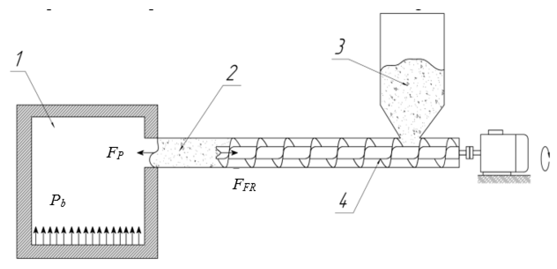
Compaction and movement of finely dispersed biomass (agricultural waste) is carried out by a screw, which feeds the material from the hopper. The feeder scheme proposed for consideration is shown in Figure 1.
To check the possibility of applying the proposed method of loading, the following data are required:
  • Properties of biomass as a bulk material—to verify the ability of layers of various types of biomass to return to a loosened state after pressure is removed.
  • Patterns of compaction of the material as it moves through the channel—to check the possibility of forming a gas-tight “plug” of biomass in the channel due to frictional forces.
  • Conditions of the movement of compacted material—to verify the possibility of the gradual movement of the formed gas-tight “plug” in the channel of the loading device.
All these data will allow us to determine the structural ratios (channel diameter and length of the sealing cylindrical area from screw to furnace boiler) and technological parameters (sealing forces and drive power), providing specified conditions for the tightness of the screw feeder.
For the studies, samples of biomass waste (sunflower husk, coniferous wood sawdust, and walnut shells) were used, provided by farming enterprises in the Dnipropetrovsk region (Ukraine). The raw material arrived in bags measuring 1 × 1 × 1 m. A distinctive feature of this raw material is that it arrived in its primary form and had not undergone any prior processing before use (such as drying, fractionation, grinding, etc.). The preparation of samples was carried out in accordance with the requirements [27] and involved the following steps: to ensure an averaged composition of each type of biomass waste, samples of 100 mL were taken from 5 places on the plane of the bag and at three levels of depth (a total of 15 samples of 500 mL volume for each type of raw material). The selected samples were then thoroughly mixed to average the composition, after which they were used for the studies.

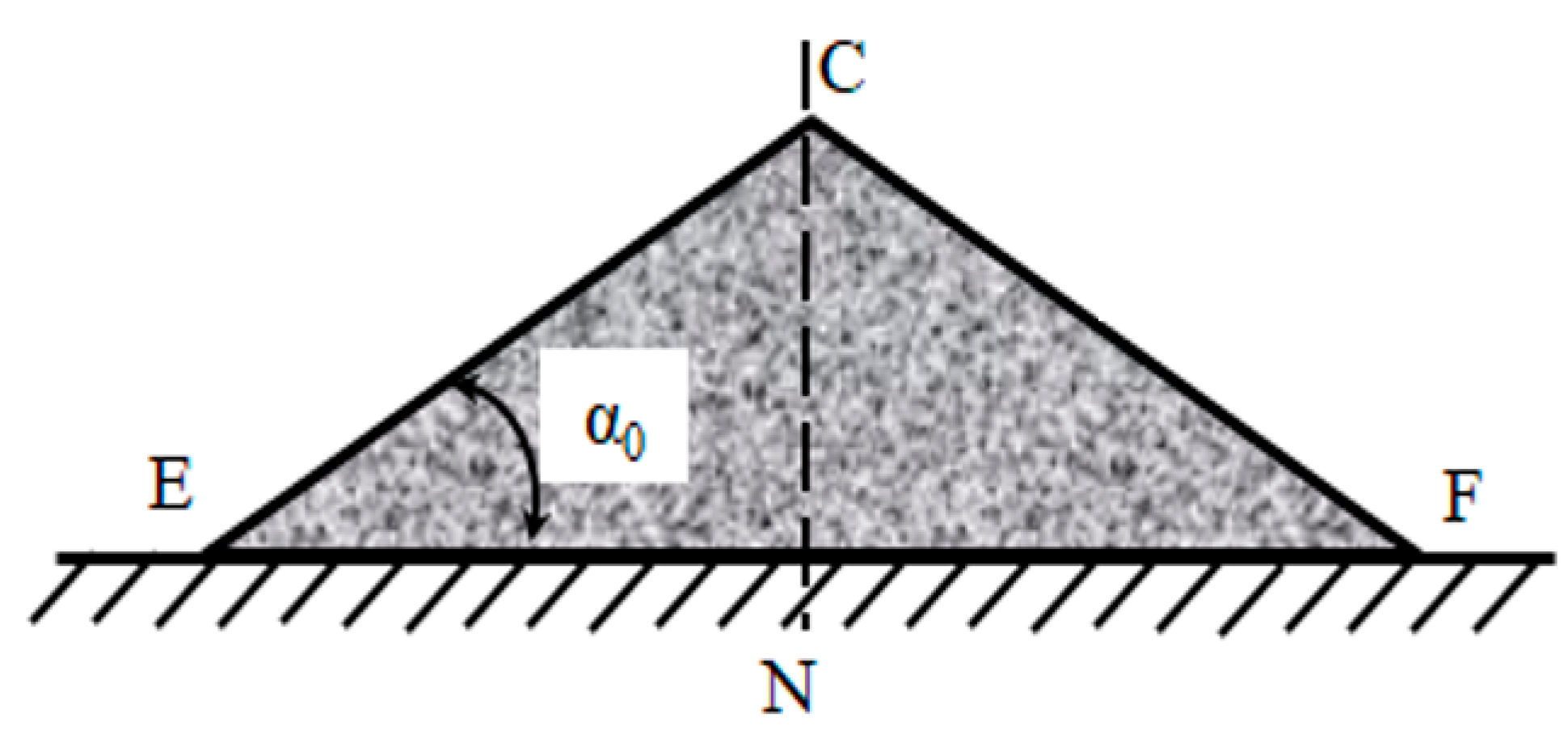
2.1. Determination of the Angle of Internal Friction of Biomass

For bulk materials, the angle of internal friction φ is equal to the angle of natural slope α0 [5]. The determination of the angle of internal friction in the study was carried out according to the methodology presented in [5,28]. The determination of the angle of the natural slope is shown in Figure 2.
The experiment used:
  • A container of a cylindrical shape.
  • Two rulers.
The sequence of actions was as follows:
  • The required amount of bulk material is measured. It is equal to the volume of the cylindrical tank:
V c = π · d 2 4 · h ,   m 3 ,
where d—capacity diameter, d = 0.105 m; h—capacity height, h = 0.127 m.
2.
A cylindrical container filled with bulk material is located on the plane. Next, the container slowly rises while the material in it is poured out and located at the angle of natural slope α0.
3.
The value of the angle of the natural slope α0 is calculated.
The angle α0 of the natural slope is determined by the formula:
t g   α 0 = C N · E F 2 ,
where C N , EF—the height and base of the triangle, as shown in Figure 2.
The experiment is carried out at least five times.

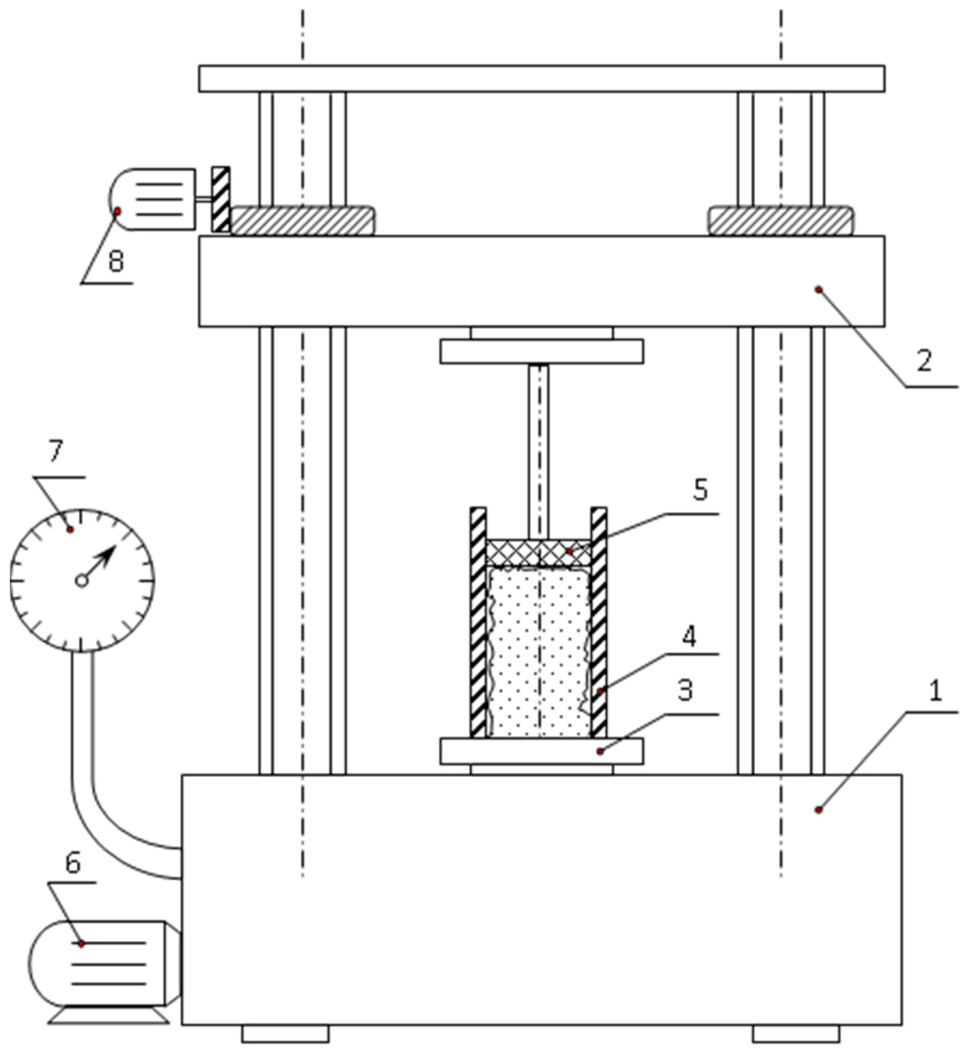
2.2. Study of Efforts Required for Biomass Layer Compaction

The study of the effort required for the compaction of the biomass layer was carried out on an experimental installation (Figure 3), consisting of:
  • A hydraulic press with adjustable pressure in the range of 0.039 ÷ 24.5 MPa.
  • Container 4, which is a pipe with a diameter of d = 146 × 10 mm, height 500 mm.
  • Piston 5 with a base diameter of dP = 140 mm.
For the experiments, a hydraulic press type P-10 produced by VO “Tochmashpribor” (USSR) was used. Key specifications of the hydraulic press include a maximum load capacity of 10 tons; the maximum stroke of the working cylinder piston is 280 mm; the allowable error in the press readings is 1% of the measured value, with a power consumption of 2.31 kW. The press is powered by a three-phase 380 V electrical network.
In the process of preparing for the experiments, it was determined that neither sawdust from coniferous trees nor walnut shells could be used in the proposed feeder for the following reasons: the sawdust forms a dense layer that does not disperse under any (even minimal) compaction, while the walnut shell, conversely, does not form a “plug” in the studied pressure range. Therefore, for further studies, only sunflower husks were used.
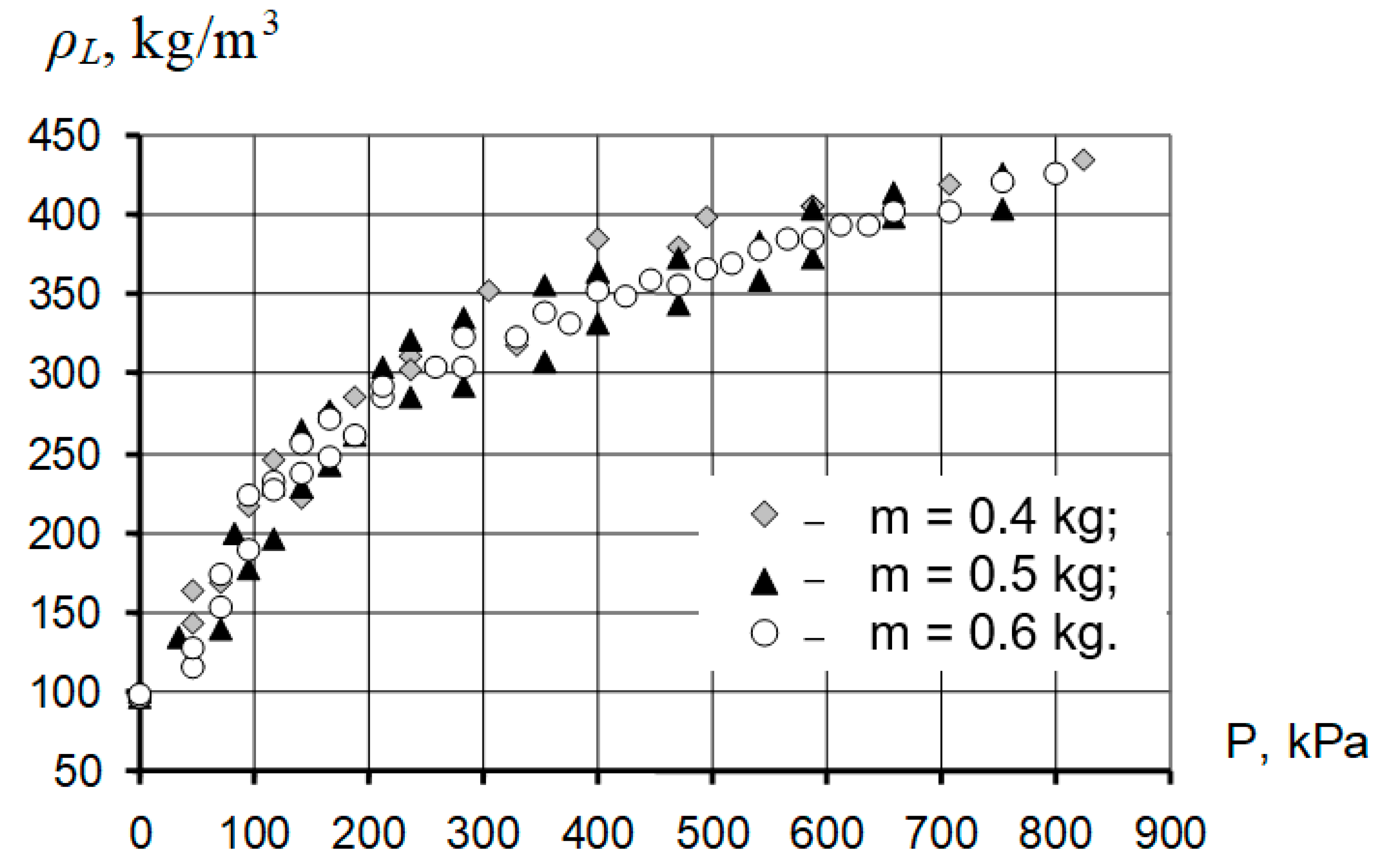
Three series of experiments were conducted to hang, weighing 0.4, 0.5, and 0.6 kg. The experiment was conducted in the following sequence. In container 4, the hanging of raw materials was poured, which was loaded with piston 5 and compressed with a hydraulic press. During the pressing process, the height of the waste layer and the oil pressure in the working cylinder were monitored. The pressure size was determined by the indications of the exemplary pressure gauge 7.
In the course of previous experiments, it turned out that when compressing the material with the pressure of the seal (on the surface of the biomass layer), more than 500 kPa, a dense briquette is formed. The density of it practically does not increase with a further increase in compression force. Therefore, the experiments were stopped when the pressure of the specified value was reached.
The experimental data allowed us to determine the density of the layer of material ρL and its porous E.

2.3. Determining the Parameters of the Screw Feeder for Loading with Sunflower Husks

The process of loading biomass waste into the furnace of the boiler unit must meet the following requirements:
  • Ensure a continuous and uniform supply of material.
  • Ensure that the level of suction in the furnace is not higher than acceptable in accordance with safety conditions.
The model of moving the biomass “cork” along the cylindrical channel was based on the condition of equality of the pushing force FP and the friction force of the biomass against the walls of the channel FFR (Figure 1):
F P = F F R .
The pushing force FP was determined using the equation:
F P = P · F S E C ,
where P—pressure created by the screw on the “cork” of biomass, kPa; FSEC—cross-sectional area of the channel, m2.
The friction force of the biomass against the walls of the channel FFR was determined using the equation:
F F R = P · μ · ε · f s i d e ,
where fside—the area of the side surface of the channel, m2; μ—friction coefficient; ε—the coefficient of the lateral spacer, which characterizes the proportion of pressure of biomass on the walls of the channel from compression pressure, similar to [22].
After the substitution of Equations (4) and (5) into Expression (3), we obtain a dependence that determines the ratio of the size of the biomass “cork” and the conditions of its movement by the channel:
d L = 4 · μ · ε ,
where d—the diameter of the screw channel, m; L—the height of the “cork” of biomass waste, m.
The value of coefficients μ and ε for sunflower husks is experimentally determined. The research was carried out on the installation shown in Figure 3.
For research, as a container, a pipe with a diameter of Ø218 × 10 mm and 500 mm high was used, which was filled with sunflower husks (the weight of the backfill was 3 kg). On a vertical press, the material was consistently pushed from one end of the container to the other until the height of the waste plug stopped changing.
A total of three experiments were conducted, as a result of which the final height of the sunflower husk stopper was determined, which amounted to 230 ± 5 mm. This value was applied to determine the numerical value of the value of the coefficients from the Equation (6):
μ · ε = 0.22 .
Thus, the height of the “cork” of biomass, that is, the length of the channel from the end of the screw to the space of the boiler furnace, should be:
L = 1.136 · d ,   m .
The determination of the choice of parameters of the process, providing a given level of gas leaks or air suction, was carried out by joint numerical solutions of the system of previous equations.
The following range of parameters was investigated in the work:
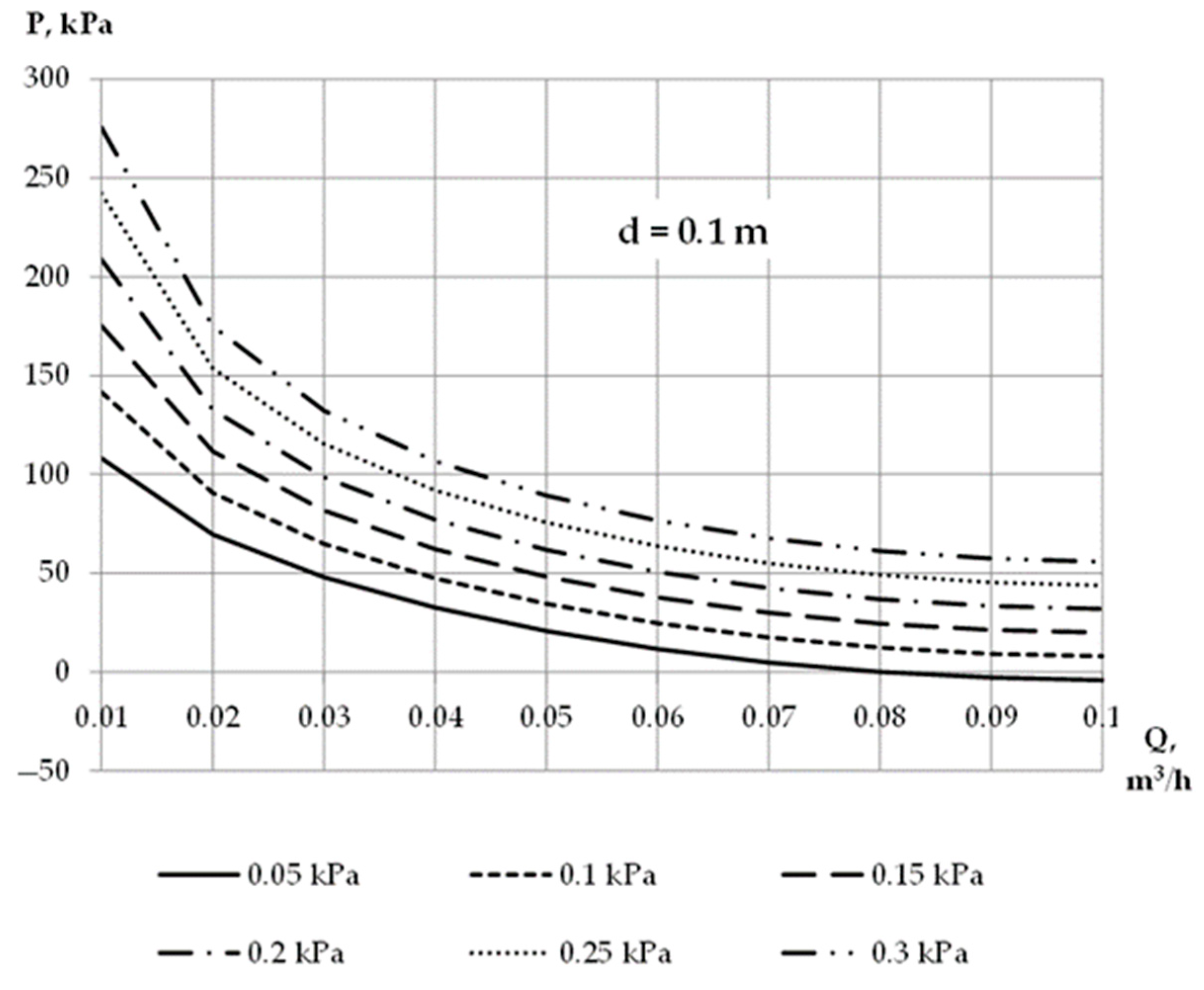
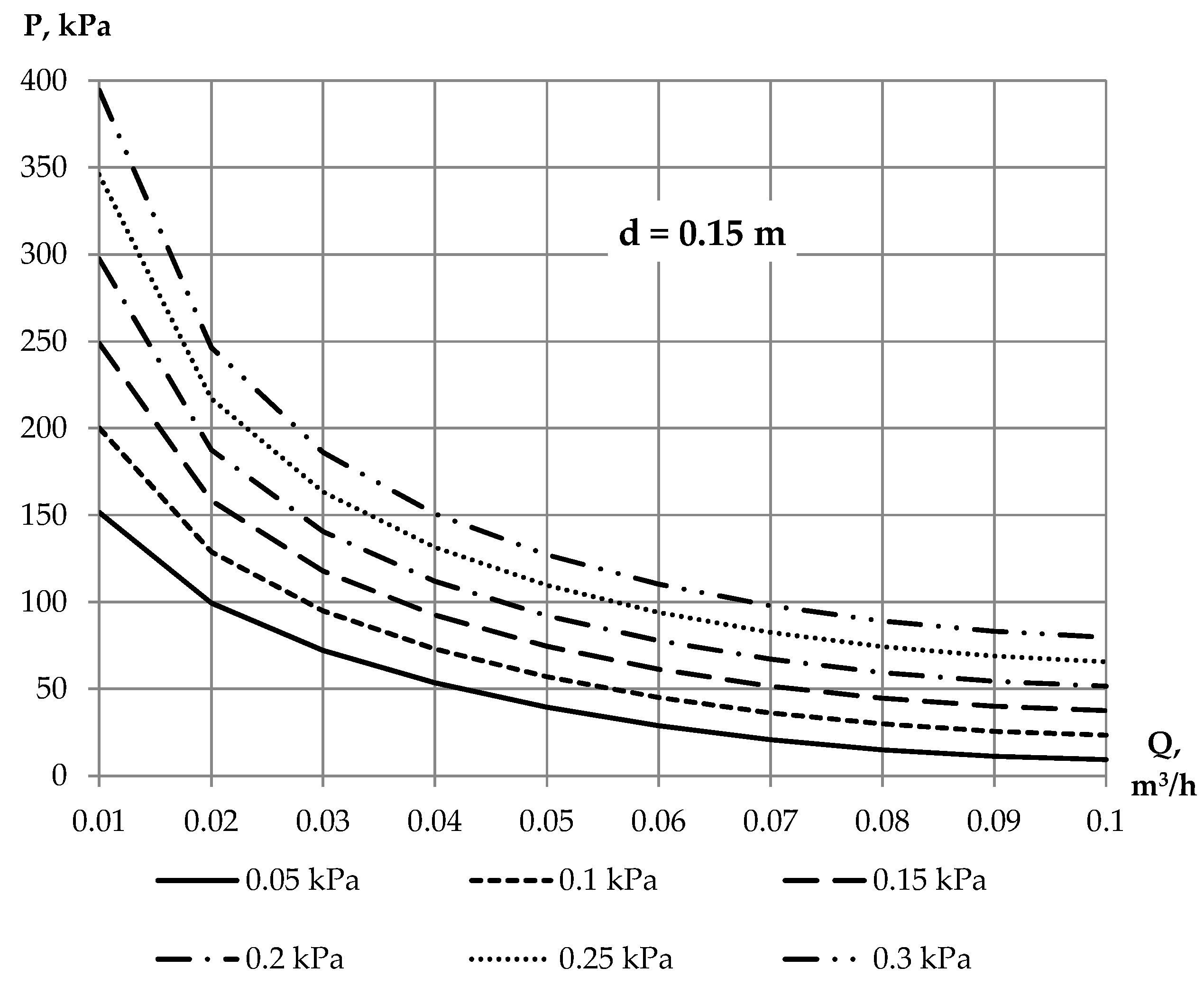
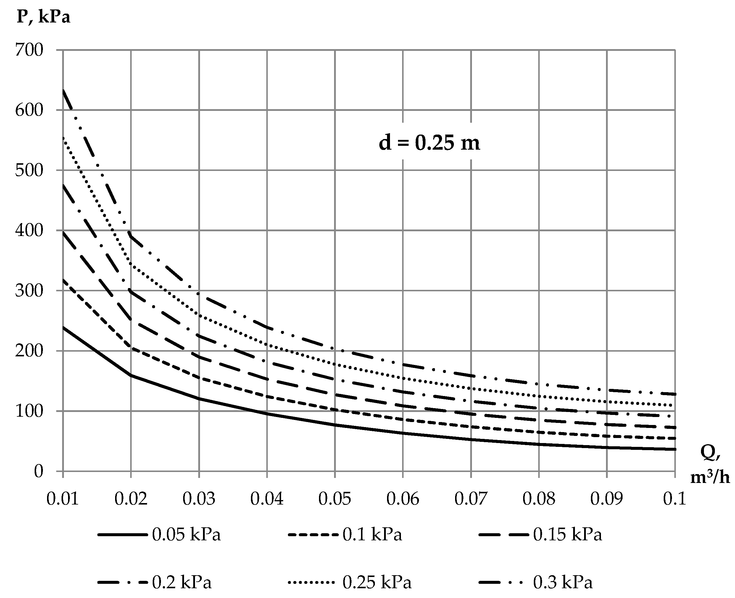
  • A pressure drop between the furnace of the boiler unit and the environment ΔP = 0.05 ÷ 0.3 kPa.
  • The permissible level of suckers in the furnace of the boiler unit Q = 0.01 ÷ 0.1 m3/h.
  • A screw channel diameter of d = 0.1 ÷ 0.25 m.
Statistical processing of the results of numerous studies in the specified range of parameters made it possible to obtain a generalized regressive dependence of the effort of compaction of the biomass waste layer on the diameter of the channel, the pressure difference between the boiler and the surrounding space, and the permissible level of suckers [29]:
P = 120 · Q 0.85 · Δ P · d + 90 · Q 0.4 · d + 345 · Q 0.35 · Δ P + + 7795 · Q 2 1486 · Q + 32 ,   P a .
Dependence (8) was used for calculated studies of the dependence of the effort of compaction of the biomass waste layer on the level of suction cups in the furnace of the boiler unit, subject to controlled pressure drops between the furnace of the boiler unit and the environment for feeders with different diameters of auger.

3. Results

3.1. Results of Determination of the Angle of Internal Friction of Biomass

During the experiment, the angle of internal friction for three types of biomass was determined: sunflower husks, sawdust, and walnut shells.
The values of the angle of internal friction for three types of biomass are given in Table 1, Table 2 and Table 3.
Based on the results of experimental studies on determining the angle of internal friction, it can be concluded that all considered types of biomass are classified as bulk materials [28]. Simultaneously, the average angle of internal friction for sawdust is 1.48 times higher than that for sunflower husks and 1.29 times higher than that for walnut shells. The average loading mass of sawdust is the lowest among the considered types of biomass, amounting to 0.169 kg. This is 2.2 times less than that of sunflower husks, whose average loading mass is 0.373 kg, and 2.6 times less than that of walnut shells (average loading mass of 0.431 kg) for the same loading volume. Such a low bulk density and high internal friction angle for sawdust indicate the likelihood of spontaneous compaction and layer suspension, which is corroborated by studies of other authors, such as [30], who also note the significant impact of sawdust moisture on its bulk properties. These characteristics of sawdust may hinder the dispersion of a “plug” made from it when entering the boiler furnace, leading to incomplete combustion of the sawdust due to limited contact with the oxidizer.

3.2. Results of Experimental Studies of Efforts Required for Biomass Layer Compaction

Figure 4 shows the graphic dependence of the density of the biomass layer on the seal pressure, which showed that in the studied range of parameters, the effect of the hanging mass on the density of the layer is insignificant.
Mathematical processing of experimental data was carried out by regression analysis using the Microsoft Excel package of programs.
As a result, we acquired the empirical dependence of the density of the biomass layer on the pressure of compaction P acting on the surface of the sunflower husk layer in the form of:
ρ L = x · P + y ,   kg / m 3 ,
where x—empirical coefficient, x = 0.4; y—average value of bulk density of sunflower husk, y = 87.3 kg/m3 [8].
The average relative error in determining the density of the biomass waste plug according to dependency (9) does not exceed ±15%.

3.3. Results of Determination of the Parameters of the Screw Feeder for Loading with Sunflower Husks

The joint solution of Equations (8) and (9) made it possible to determine the value of the compaction of the layer, which corresponds to the forces of compaction of the sunflower husk layer, depending on the levels of suckers in the furnace of the boiler unit, subject to controlled pressure drops between the furnace of the boiler unit and the environment for feeders with different diameters of auger. The results of calculations are given in Table 4, Table 5, Table 6 and Table 7.
Based on the results of the calculations presented in Table 4, Table 5, Table 6 and Table 7, regarding the dependence of the density of the sunflower husk layer on the compaction pressure in a screw feeder with a screw diameter in the range of 0.1 to 0.25 m, it can be concluded that to ensure a suction level through the feeder into the furnace of the boiler unit of no more than 0.1 m3/h, with a pressure difference between the boiler furnace and the surrounding environment (ΔP) of 0.05 to 0.3 kPa, the relative increase in the density of the “plug” made from sunflower husks should not exceed the bulk density of the uncompacted layer by more than 11.5%.
The results of calculations on the dependence of the effort of compaction of the biomass waste layer on the level of suction cups in the furnace of the boiler unit, subject to controlled pressure drops between the furnace of the boiler unit and the environment for feeders with different diameters of auger, are given in the form of graphic dependencies in Figure 5, Figure 6, Figure 7 and Figure 8.
The provided graphs are of practical significance and can be used to select the geometric and operational characteristics of the feeding device within the specified range of parameters.

4. Conclusions

When working with a solid fuel boiler on finely dispersed biomass, a necessary requirement is the sealing of the boiler working space, which prevents air suction when working under discharge. The paper considers the method of loading sunflower husks into the boiler unit with a screw feeder, which ensures the gas density of the working chamber due to a compacted layer of biomass waste (“cork”), formed as a result of the movement of waste through the cylindrical channel in the tail of the screw (in front of the boiler furnace chamber). Such a method will help to avoid the installation of additional mechanical devices (cut-offs, latches, etc.), which increase capital expenditures and complicate the operation of the entire energy complex.
To check the possibility of using the proposed method of loading in the work, the following tasks were solved:
  • We experimentally determined the properties of biomass as a bulk material (angle of internal friction) for three types of biomass: sunflower husks, coniferous wood sawdust, and walnut shells. The results showed that sawdust from coniferous wood has an average angle of internal friction 1.48 times higher than that of sunflower husks and 1.29 times higher than that of walnut shells. Meanwhile, the average loading mass of sawdust is 2.2 times less than that of sunflower husks and 2.6 times less than that of walnut shells. This low bulk density and high internal friction angle for sawdust suggest a likelihood of spontaneous compaction and layer suspension, confirmed by a previous publication [30], which also notes the significant impact of sawdust moisture on its bulk properties. These characteristics of sawdust might hinder the dispersal of a “plug” made from it upon entering the boiler furnace, leading to incomplete combustion due to limited contact with the oxidizer.
  • We performed experimental studies on the compaction force of the biomass layer. The empirical dependence of the biomass layer density on the compaction pressure acting on the surface of the sunflower husk layer was obtained. It was determined that to ensure a suction level through a screw feeder with a diameter of 0.1 to 0.25 m into the furnace of the boiler unit of no more than 0.1 m3/h, with a pressure difference between the boiler furnace and the surrounding environment (ΔP) of 0.05 to 0.3 kPa, the relative increase in the density of the “plug” from sunflower husks should not exceed the bulk density of the uncompacted layer by more than 11.5%.
  • We experimentally determined that the geometric dimensions of the “plug” from sunflower husks, which provide the necessary level of gas tightness of the feeder, depend only on the diameter of the channel and are 1.136·d.
  • The dependencies of the compaction force of the biomass waste layer on the level of suction (in the studied range Q = 0.01 to 0.1 m3/h) into the furnace of the boiler unit under controlled pressure drops (in the studied range ΔP = 0.05 to 0.3 kPa) between the boiler furnace and the surrounding environment for feeders with different screw diameters (d = 0.1 to 0.25 m) were calculated. These dependencies can be used for the practical determination of the geometric and operational parameters of the screw feeder when operating a boiler unit using sunflower husks.

Author Contributions

Conceptualization, Y.S. and A.C.; methodology, Y.S.; software, Y.S. and D.S.; validation, O.B., Y.S., A.C. and A.Z.; formal analysis, Y.S. and I.Z.; investigation, Y.S. and D.S.; resources, Y.S., A.Z. and I.Z.; data curation, Y.S.; writing—original draft preparation, Y.S. and A.C.; writing—review and editing, O.B., A.C., A.Z. and I.Z.; visualization, D.S.; supervision, Y.S. and A.Z. All authors have read and agreed to the published version of the manuscript.

Funding

This research received no external funding.

Data Availability Statement

Data are contained within the article.

Conflicts of Interest

The authors declare no conflicts of interest.

References

  1. Hurtig, O.; Buffi, M.; Scarlat, N.; Motola, V.; Georgakaki, A.; Letout, S.; Mountraki, A.; Joanny, G. Clean Energy Technology Observatory: Advanced Biofuels in the European Union—2022 Status Report on Technology Development, Trends, Value Chains and Markets; Publications Office of the European Union: Luxembourg, 2022. [Google Scholar] [CrossRef]
  2. IRENA. Solid Biomass Supply for Heat and Power: Technology Brief; International Renewable Energy Agency: Abu Dhabi, United Arab Emirates, 2018. [Google Scholar]
  3. Bala-Litwiniak, A. Environmental and economic aspects of combustion of biomass pellets containing a waste glycerol. Combust. Sci. Technol. 2021, 193, 1998–2008. [Google Scholar] [CrossRef]
  4. Stanytsina, V.; Artemchuk, V.; Bogoslavska, O.; Zaporozhets, A.; Kalinichenko, A.; Stebila, J.; Havrysh, V.; Suszanowicz, D. Fossil Fuel and Biofuel Boilers in Ukraine: Trends of Changes in Levelized Cost of Heat. Energies 2022, 15, 7215. [Google Scholar] [CrossRef]
  5. Artyukhov, A.M.; Orishaka, O.V.; Orishaka, V.O.; Malashenko, Y.A. Research of physical and mechanical properties of fine-grained bulk materials. Technol. Agric. Prod. Branch Eng. Autom. 2011, 24, 72–76. [Google Scholar]
  6. Horák, J.; Bilan, Y.; Dankevych, A.; Nitsenko, V.; Kucher, A.; Streimikiene, D. Bioenergy production from sunflower husk in Ukraine: Potential and necessary investments. J. Bus. Econ. Manag. 2023, 24, 1–19. [Google Scholar] [CrossRef]
  7. Havrysh, V.; Kalinichenko, A.; Pysarenko, P.; Samojlik, M. Sunflower Residues-Based Biorefinery: Circular Economy Indicators. Processes 2023, 11, 630. [Google Scholar] [CrossRef]
  8. Shevchenko, G.L.; Shyshko, Y.V.; Usenko AYu Kremenova, E.V. Study of the Main Characteristics of Biomass Waste as a Fuel. Metallurgical Heat Engineering: Collection of Scientific Works of the National Metallurgical Academy of Ukraine; PE Grek O.S.: Dnipropetrovsk, Ukraine, 2007; pp. 305–313. [Google Scholar]
  9. Hubetska, T.S.; Kobylinska, N.G.; García, J.R. Sunflower biomass power plant by-products: Properties and its potential for water purification of organic pollutants. J. Anal. Appl. Pyrolysis 2021, 157, 105237. [Google Scholar] [CrossRef]
  10. Kazmi, B.; Taqvi, S.A.A.; Naqvi, S.R.; Mirani, A.A.; Shahbaz, M.; Naqvi, M.; Juchelková, D.; Eldesoky, G.E. Techno-economic assessment of sunflower husk pellets treated with waste glycerol for the Bio-Hydrogen production—A Simulation-based case study. Fuel 2023, 348, 128635. [Google Scholar] [CrossRef]
  11. Isemin, R.; Tabet, F.; Nebyvaev, A.; Kokh-Tatarenko, V.; Kuzmin, S.; Milovanov, O.; Klimov, D.; Mikhalev, A.; Dobkin, S.; Zhulaev, Y. Prediction of the Behavior of Sunflower Husk Ash after Its Processing by Various Torrefaction Methods. Energies 2022, 15, 7483. [Google Scholar] [CrossRef]
  12. Cui, H.; Grace, J.R. Pneumatic conveying of biomass particles: A review. China Particuology 2006, 4, 183–188. [Google Scholar] [CrossRef]
  13. Geletukha, G.; Drahniev, S.; Zheliezna, T.; Bashtovyi, A. Prospects of Sunflower Residues Use for Energy. Position Paper # 25. 2020. Available online: https://uabio.org/wp-content/uploads/2020/10/uabio-position-paper-25-en-1.pdf (accessed on 1 August 2023).
  14. Road Map of Bioenergy Development in Ukraine until 2050 and Action Plan until 2025. Available online: https://saf.org.ua/wp-content/uploads/2021/06/Dorozhnya-karta-rozvytku-bioenergetyky-v-Ukrayini-do-2050-roku-i-Plan-dij-do-2025.pdf (accessed on 13 June 2023).
  15. Bala-Litwiniak, A.; Musiał, D. Computational and Experimental Studies of Selected Types of Biomass Combustion in a Domestic Boiler. Materials 2022, 15, 4826. [Google Scholar] [CrossRef]
  16. Bala-Litwiniak, A.; Musiał, D.; Nabiałczyk, M. Computational and Experimental Studies on Combustion and Co-Combustion of Wood Pellets with Waste Glycerol. Materials 2023, 16, 7156. [Google Scholar] [CrossRef]
  17. Zaporozhets, A. Analysis of control system of fuel combustion in boilers with oxygen sensor. Period. Polytech. Mech. Eng. 2019, 64, 241–248. [Google Scholar] [CrossRef]
  18. Babak, V.P.; Mokiychuk, V.M.; Zaporozhets, A.A.; Redko, A.A. Improving the efficiency of fuel combustion with regard to the uncertainty of measuring oxygen concentration. East. Eur. J. Enterp. Technol. 2016, 6, 54–59. [Google Scholar] [CrossRef]
  19. Perea-Moreno, M.-Á.; Manzano-Agugliaro, F.; Perea-Moreno, A.-J. Sustainable Energy Based on Sunflower Seed Husk Boiler for Residential Buildings. Sustainability 2018, 10, 3407. [Google Scholar] [CrossRef]
  20. Dai, J.; Grace, J.R. Biomass granular screw feeding: An experimental investigation. Biomass Bioenergy 2011, 35, 942–955. [Google Scholar] [CrossRef]
  21. Dai, J.; Cui, H.; Grace, J.R. Biomass feeding for thermochemical reactors. Prog. Energy Combust. Sci. 2012, 38, 716–736. [Google Scholar] [CrossRef]
  22. Yalechko, V.I. Improving the Efficiency of the Energy-Technological Process of Burning the Healthy Wood Biomass. Master’s Thesis, National University “Lviv Polytechnic”, Lviv, Ukraine, 2021. [Google Scholar]
  23. Gomes, T.L.; Lourenço, G.A.; Ataíde, C.H.; Duarte, C.R. Biomass feeding in a dilute pneumatic conveying system. Powder Technol. 2021, 391, 321–333. [Google Scholar] [CrossRef]
  24. Barroso, G.; Hediger, L.; Nussbaumer, T. Modelling and validation of biomass combustion in a screw burner. Fuel 2019, 254, 115672. [Google Scholar] [CrossRef]
  25. Dai, J.; Grace, J.R. A model for biomass screw feeding. Powder Technol. 2008, 186, 40–55. [Google Scholar] [CrossRef]
  26. Bulinko, M.G.; Petrovsky, E.E. Technology of Peat-Briquetting; Nedra: Moscow, Russia, 1968; 312p. [Google Scholar]
  27. Letter from 13.09.2011 № 19/3-10.2/4839-EП Regarding the Sampling for Laboratory Research” Appears to Be a Citation of a Specific Document or Guideline, Possibly Related to Standards or Procedures for Sampling in the Context of Laboratory Studies. Available online: https://online.budstandart.com/ua/catalog/doc-page.html?id_doc=84209 (accessed on 6 December 2023).
  28. Naumenko, Y.V. Metodychni Rekomendatsii do Vyvchennia Rozdilu “Vlastyvosti Robochykh Seredovyshch Barabannykh Mashyn» Navchalnoi Dystsypliny «Robochi Protsesy Mashyn Barabannoho Typu” Dlia Studentiv Spetsialnosti 133 “Haluzeve Mashynobuduvannia” Dennoi ta Zaochnoi Formy Navchannia; NUVHP: Rivne, Ukraine, 2017; 95p. [Google Scholar]
  29. Gubinskiy, M.V.; Shyshko, Y.V. Study of the hydraulic resistance of a dense layer of biomass waste. Metall. Heat. 2001, 4, 145–151. [Google Scholar]
  30. Stasiak, M.; Molenda, M.; Bañda, M.; Gondek, E. Mechanical properties of sawdust and woodchips. Fuel 2015, 159, 900–908. [Google Scholar] [CrossRef]
Figure 1. Scheme of the screw feeder with a gas-sealing “plug” of biomass: 1—furnace of the boiler unit; 2—“cork” of biomass; 3—loading hopper; 4—screw feeder.
Energies 17 00590 g001
Figure 2. Determination of the angle of natural slope.
Energies 17 00590 g002
Figure 3. Scheme of experimental installation: 1—working cylinder; 2—moving platform; 3—press table; 4—container; 5—piston; 6—pump; 7—pressure gauge; 8—electric motor.
Energies 17 00590 g003
Figure 4. Dependence of the density of the biomass layer on the sealing force.
Energies 17 00590 g004
Figure 5. Parameters of the screw feeder with a screw diameter d = 0.10 m.
Energies 17 00590 g005
Figure 6. Parameters of the screw feeder with a screw diameter d = 0.15 m.
Energies 17 00590 g006
Figure 7. Parameters of the screw feeder with a screw diameter d = 0.20 m.
Energies 17 00590 g007
Figure 8. Parameters of the screw feeder with a screw diameter d = 0.25 m.
Energies 17 00590 g008
Table 1. The angle of internal friction for sunflower husks.
Iteration of ExperimentWeight, kg t g   α 0 φ
10.3650.00544518.5
20.3600.00646322.2
30.3680.00719225.0
40.3820.0073825.8
50.3920.00812528.8
Table 2. The angle of internal friction for sawdust.
Iteration of ExperimentWeight, kg t g   α 0 φ
10.1580.0103638.7
20.1610.0092433.5
30.1770.0104439.0
40.1770.0106239.9
50.1700.00787827.8
Table 3. The angle of internal friction for walnut shells.
Iteration of ExperimentWeight, kg t g   α 0 φ
10.4380.0082629.3
20.4450.00750826.3
30.4220.00815528.9
40.4160.00787527.8
50.4340.00750826.3
Table 4. Dependence of sunflower husk layer density on seal pressure in screw feeder (d = 0.10 m).
Q, m3/hΔP = 0.05 kPaΔP = 0.10 kPaΔP = 0.15 kPaΔP = 0.20 kPaΔP = 0.25 kPaΔP = 0.30 kPa
P, kPaρL, kg/m3P, kPaρL, kg/m3P, kPaρL, kg/m3P, kPaP, kPaρL, kg/m3P, kPaρL, kg/m3P, kPa
0.01108.291.46141.792.06175.292.60208.893.08242.393.53275.893.94
0.0269.590.6390.691.11111.691.53132.791.91153.892.26174.992.59
0.0347.990.0764.890.5281.790.9198.591.27115.491.60132.391.90
0.0432.589.5847.390.0562.290.4577.090.8191.991.13106.791.43
0.0520.789.1234.489.6548.190.0761.890.4575.590.7889.291.08
0.0611.688.6624.689.2937.689.7550.690.1563.690.4976.690.80
0.074.888.1817.488.9729.989.4942.589.9155.090.2767.690.59
0.080.087.3512.288.7024.589.2836.889.7349.090.1061.390.43
0.09−2.986.619.188.5121.289.1433.389.6145.389.9957.490.33
0.10−4.186.497.988.4219.889.0831.889.5543.789.9455.790.28
Table 5. Dependence of sunflower husk layer density on seal pressure in screw feeder (d = 0.15 m).
Q, m3/hΔP = 0.05 kPaΔP = 0.10 kPaΔP = 0.15 kPaΔP = 0.20 kPaΔP = 0.25 kPaΔP = 0.30 kPa
P, kPaρL, kg/m3P, kPaρL, kg/m3P, kPaρL, kg/m3P, kPaρL, kg/m3P, kPaρL, kg/m3P, kPaρL, kg/m3
0.01151.692.23200.292.96248.793.61297.394.20345.894.74394.495.24
0.0299.491.29128.891.84158.292.33187.692.78217.093.19246.493.58
0.0372.190.7094.991.20117.791.64140.592.04163.292.41186.092.76
0.0453.490.2272.990.7292.491.14111.991.53131.391.88150.892.21
0.0539.589.8157.090.3274.590.7592.191.14109.691.49127.191.81
0.0628.889.4545.189.9961.390.4377.690.8293.991.18110.291.50
0.0720.789.1236.189.7051.690.1767.090.5782.490.9397.991.26
0.0814.988.8429.789.4844.689.9759.490.3874.290.7589.191.07
0.0911.288.6425.689.3240.089.8354.390.2568.790.6283.190.95
0.109.388.5223.489.2437.589.7551.690.1765.690.5479.790.87
Table 6. Dependence of sunflower husk layer density on seal pressure in screw feeder (d = 0.20 m).
Q, m3/hΔP = 0.05 kPaΔP = 0.10 kPaΔP = 0.15 kPaΔP = 0.20 kPaΔP = 0.25 kPaΔP = 0.30 kPa
P, kPaρL, kg/m3P, kPaρL, kg/m3P, kPaρL, kg/m3P, kPaρL, kg/m3P, kPaρL, kg/m3P, kPaρL, kg/m3
0.01195.192.89258.793.73322.294.48385.895.16449.495.78513.096.36
0.02129.291.85167.092.47204.793.02242.593.53280.294.00318.094.43
0.0396.391.23125.091.77153.792.26182.492.70211.193.11239.893.49
0.0474.490.7598.591.27122.691.73146.792.14170.892.53194.992.88
0.0558.290.3579.690.87100.991.32122.391.72143.692.09165.092.44
0.0645.990.0165.590.5485.090.99104.691.39124.291.76143.792.10
0.0736.689.7254.990.2673.290.7291.591.13109.891.49128.291.83
0.0829.889.4947.290.0564.690.5282.090.9299.491.29116.891.62
0.0925.389.3142.089.8958.790.3675.490.7792.191.14108.991.47
0.1022.889.2139.089.8055.290.2771.490.6887.691.04103.891.37
Table 7. Dependence of sunflower husk layer density on seal pressure in screw feeder (d = 0.25 m).
Q, m3/hΔP = 0.05 kPaΔP = 0.10 kPaΔP = 0.15 kPaΔP = 0.20 kPaΔP = 0.25 kPaΔP = 0.30 kPa
P, kPaρL, kg/m3P, kPaρL, kg/m3P, kPaρL, kg/m3P, kPaρL, kg/m3P, kPaρL, kg/m3P, kPaρL, kg/m3
0.01175.692.60317.194.42395.795.26474.496.01553.096.71631.697.35
0.02122.291.72205.293.03251.393.64297.494.20343.594.71389.695.19
0.0392.891.15155.192.28189.792.81224.393.29258.993.74293.594.15
0.0472.390.70124.091.75152.892.24181.592.69210.293.10238.993.48
0.0556.890.31102.191.34127.391.81152.592.24177.792.63202.993.00
0.0644.889.9885.991.01108.791.47131.691.89154.492.27177.392.63
0.0735.689.6973.790.7394.991.20116.191.61137.391.99158.492.34
0.0828.889.4564.790.5284.790.98104.791.39124.691.77144.692.11
0.0924.289.2758.490.3677.590.8296.591.23115.691.60134.691.94
0.1021.589.1654.590.2572.890.7191.291.12109.591.49127.891.82
Disclaimer/Publisher’s Note: The statements, opinions and data contained in all publications are solely those of the individual author(s) and contributor(s) and not of MDPI and/or the editor(s). MDPI and/or the editor(s) disclaim responsibility for any injury to people or property resulting from any ideas, methods, instructions or products referred to in the content.

