Abstract
This article is about the detection of a partial inter-turn short-circuit fault in a brushless motor with permanent magnets (BLPMM). The detection of a single inter-turn short circuit is a difficult issue. The authors of this article tested the sensitivity of the tested powertrain damage detection method. The diagnostic method developed for BLPMM allows for any configuration of the motor winding. A number of analysed configurations have been applied for the combined star–delta connection (YΔ). For the combined star–delta connection Y/Δ, the problem of partial short circuit at two locations was analysed. In the first case, this was the short-circuit winding phenomena in the star part (SC1). In the second case, the short circuit was connected in part to the delta (SC2). A mathematical model has been developed that takes into account both the type of connection and the chance of a partial short circuit of the coil. Based on numerical calculations, the sensitivity of diagnostic methods is designated for both cases. Furthermore, the impact of partial short circuits on motor performance was also examined. The effect of a partial inter-turn short-circuit fault on motor parameters was also determined. Laboratory verification was carried out.
1. Introduction
Brushless motors with permanent magnets are now actually used more widely than several years ago. A significant proportion of servo drives use brushless permanent magnet motors (BLPMM) [1,2]. These are favoured due to their smaller dimensions, high energy conversion efficiency, and higher dynamics than, for example, typical induction motors (IM) [3]. A large influence on the increase in the practical application of BLPMM is the automotive industry. In this case, BLPMM are used to power electric or hybrid cars [4]. In the case of hybrid vehicles, they are also used to generate electricity (as generators) [5]. BLPMM are also used in small and large aircrafts or flying objects, which are ideal for their use [6].
Due to the wide range of applications for BLPMM, potential issues that may arise during its operation must be considered. Typically, a power electronics system is required for the proper functioning of the BLPMM. Depending on the mode of operation, information about the current position of the rotor is usually necessary. Irregularities in the operation of such a drive system may occur on the side of the power electronics system. These can include faults within the power converter system itself [7,8]. Irregularities can also arise in the accurate detection of the rotor position [9,10]. There are diagnostic methods available that allow the detection of irregularities originating in the power electronics system or control system [8,11].
Problems can also arise on the side of the motor itself; typically, for example, these are open circuits in the windings (OC) [12] or partial winding short circuits (SC) [13]. Detecting open circuits in the windings is relatively easier. Existing diagnostic methods generally handle this problem well [14]. A much greater challenge is the detection of partial winding short circuits, which is a significantly more complex problem. Generally, detecting larger short circuits does not pose much of a challenge [13,15,16,17,18,19]. Current SC detection methods are generally based on search coils [19] and winding function theory (WFT) to calculate impedance [16,20], current measurement [13,17,18], and voltage [21].
However, for most known diagnostic methods, detecting short circuits that even involve a single turn can be quite problematic. The use of a search coil [19] provides high efficiency but requires additional windings. In most motors, this approach is unacceptable. The method can detect a short circuit of three coils. However, the number of motor phase windings is not specified in article [19]. Short circuit detection discussed in [20] is based on input impedance. Methods based on winding function theory (WTF) generally do not detect single-turn short circuits. This is the case for operations below 40% of nominal speed. Diagnostics based on phase current measurement can be quite effective [17]. Using the third harmonic of the phase current, it is possible to detect single turn short circuits (1.39%). A major limitation of the method is the condition of operating with a higher load or the problem of detecting a lower speed. The voltage method [21] is effective but limited to the configuration of the star winding. The tests were carried out at 2% of the number of shorted coils. Its additional limitation is the problem of fault detection at lower speeds. Furthermore, the study did not determine the effect of the change in the load torque when changing the sensitivity of the method.
In article [22], the use of a voltage signal was suggested for the monitoring and diagnostics of BLPMM. It has been shown that it is possible to detect OC or SC regardless of the winding configuration used (star—Y, delta—Δ, mixed star/delta—YΔ. The SC state, as analysed in the publications, involved a relatively large part of the SC.
According to the authors, the method presented in [22] for BLPMM monitoring and diagnostics can be used to detect single-turn short circuits. The article demonstrates how winding configuration affects fault detection. According to the authors, the proposed diagnostic method has been shown to be more universal. As shown in the paper [22], it allows short circuits to be detected, regardless of the type of BLPMM winding configuration. The article [22] did not focus on the problem of detecting single-turn short circuits. This issue is included in this article. An unusual mixed star/delta winding combination (Y/Δ) was used for this purpose. This article analyses short circuits that arise in the star part (SC1) and the delta part (SC2). This is a new approach used to analyse the impact of partial short circuiting, their monitoring, and BLPMM diagnostics. The effect of the winding configuration on the sensitivity of the proposed diagnostic method was shown.
The introduction to the article reviews the literature on the issue under consideration. The second chapter presents the primary purpose of the analysed BLPMM, its parameters, the stator winding configuration, and the laboratory test rig. A mathematical model that takes into account the configuration of YΔ and the state of the partial SC is included in Section 3. An analysis of the impact of partial SC on selected time courses is included in Section 4. An analysis of the higher harmonic content of the diagnostic signal is provided in Section 5. An example of laboratory verification is included in Section 6. A summary is included in Section 7.
2. Winding Configuration and Laboratory Stand Test
For the tests, a prototype brushless motor with permanent magnets (BLPMM) was used. The BLPMM construction was modelled for a small unmanned flying hybrid drive object (Figure 1a). A cross-section of the BLPMM is shown in Figure 1b.
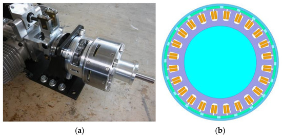
Figure 1.
View (a) hybrid drive and (b) cross-section of BLPMM.
Table 1 shows the basic parameters of the BLPMM tested.

Table 1.
Selected original parameters of BLPMM.
A schematic of the power converter and winding connections is shown in Figure 2.
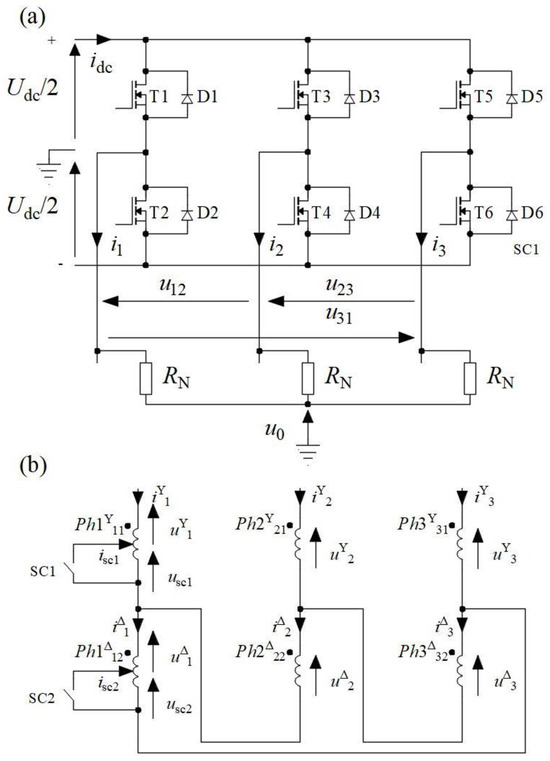
Figure 2.
Scheme (a) power converter, (b) winding connections.
The closing SC1 key implements the state of SC1 for star part configuration YΔ. The SC2 state occurs after closing the SC2 key. In this case, the SC occurs in a part of the winding connected in a delta.
Figure 2a shows a system to monitor and diagnose the operating status of the BLPMM. The authors used the zero-voltage component (ZEV) method proposed for BLPMM fault detection [21]. The paper [21] used the voltage u0s that requires the availability of the neutral point of the motor as a diagnostic signal. This is an important limitation of this approach. In an article [22], the authors demonstrated that it is possible to diagnose BLPMM based on the u0. signal. This allows any BLPMM winding configuration to be used. In the article [22], it was shown that the FFT analysis of the diagnostic signal u0 allows for the monitoring and diagnosis of the operating state of the BLPMM. The value of the diagnostic harmonic is important. This is the first harmonic of the u0 signal:
Under ideal operating conditions, the diagnostic signal u0 contains only the third harmonic and its odd multiples (9th, 15th, etc.). The appearance of the first harmonic f1 in particular suggests the emergence of an asymmetric operating condition (not necessarily a fault). A simplified block diagram of the proposed monitoring and diagnostic method is shown in Figure 3.
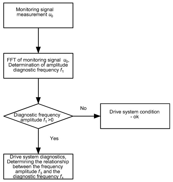
Figure 3.
Flowchart of the proposed monitoring and diagnostic method.
The monitoring and diagnostic method proposed by the authors detects partial short circuits (SC) or interruptions (OC) in phase windings. OC detection is clear. For SC, the sensitivity of the proposed monitoring and diagnostic method must be determined. The effect of SC on the proposed diagnostic signal depends on the number of shorted turns in the BLPMM winding.
The laboratory test rig shown in Figure 4 was used to verify the numerical results.
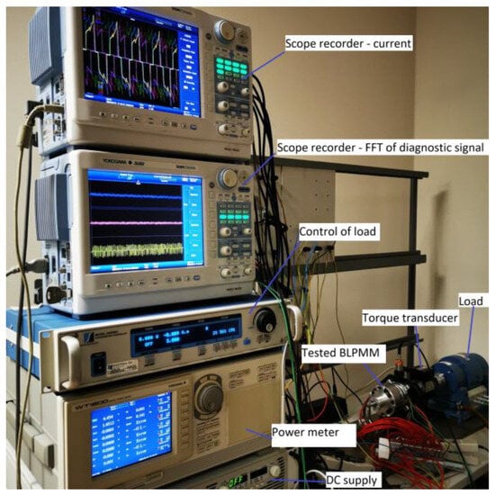
Figure 4.
Laboratory test rig.
The laboratory bench was equipped with a dynamometer with accessories, a torque transducer, a power meter, scope recorder, and a DC power supply.
3. Model of SC Fault Motor SC BLPM
3.1. A. No Constraints Star–Delta (YΔ) BLPM Motor SC Fault Model
The mathematical model of a three-phase BLPM motor (Figure 1) is presented for machines with star–delta (YΔ) winding configurations (Y). The model was formulated assuming the linearity of the magnetic circuit and short circuit of the winding coils with current Back EMF (BEMF) voltage , and the parameters of —resistance and —inductance. Vectors voltages , currents , and BEMF voltages are defined as follows:
The structure of the YΔ BLPM motor SC fault without constraints model can be written:
where the vectors of voltages , currents , and phase BEMF voltage are as follows:
The following symbols are used in (4): is total electromagnetic torque, J—rotor moment of inertia, —mechanical angular speed of the rotor, D—rotor damping of viscous friction coefficient, and —load torque. In (4) matrices, the resistances R and inductances are defined:
The matrices resistances and coefficients of self- and mutual inductances; for example, , , and in (6) have the following structures:
where θ—electrical rotor angle, —electrical angular speed, and p—machine number of pole pairs. For example, the phase BEMF voltage vectors and voltage in (6) are defined:
—BEMF constant of one phase and short circuit and —phase trapezoidal functions, profile BEMF.
3.2. B. Star–Delta (YΔ) Line Voltage BLPM SC Motor Fault Model
Additional constraints on voltages and currents are imposed by the arrangement of motor phase windings in star–delta (YΔ) configuration. The voltages and current line-to-line (L) vectors are defined:
The constraint matrices are defined, with —star, —delta, E—Unit matrix, and —YΔ:
The relationship of line-to-line voltages and line currents in a star–delta (YΔ) connection can be written as follows:
Including the constraint (12) in (4) and (5), the final equations of the YΔ BLPM Motor SC Fault Model can be written:
where the vectors voltages , currents , voltages BEMFs , matrices, the resistances , and inductances are defined:
Equations (13)–(16) generally constitute a mathematical model of the BLPM Motor with a short-circuit stator fault with combined YΔ winding configurations.
4. Results—Waveforms of Currents and Electromagnetic Torque
Under numerical calculation conditions, tests can be carried out under any condition. Laboratory tests significantly limit the possibilities of verifying numerical calculations. Under numerical conditions, the dependence of the RMS SC current was determined as a function of the rotational speed (with the SC1 key closed). The SC1 key short-circuits the two poles of the motor’s phase 1 (25% of the total number of coils). Figure 5 shows the results of the calculations.
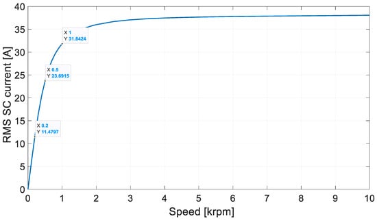
Figure 5.
RMS SC current vs. speed.
The resulting Isc vs. n characteristic is typical of synchronous machines. The rms value of the current in each path is 10.5 A. At 200 rpm under laboratory conditions, the SC effect allows the machine to run for a long time. At n = 500 rpm, the short-circuit current already reaches more than 23 A (two times the rated value). The short-circuit current reaches a value approximately three times higher at 1000 rpm. To reduce the possibility of damaging the permanent magnets, the BLPMM operating point was set at 500 rpm. At this operating point, the SC produces the desired effect without fear of damaging the permanent magnets. The thermal effect will be noticeable, but this allows for laboratory testing.
The present work [22] analysed the short-circuit condition of the partial winding for the tested construction. The results of the work were limited to an SC with an identical number of windings (two poles) for different motor winding configurations. It shows the waveforms of conductor currents, phase currents, short-circuit current, and electromagnetic torque. A proprietary method based on the detection of diagnostic frequencies included in the voltage signal u0 was used to detect the short-circuit condition (Figure 2a). It was shown that the method detected the SC state independently of the analysed winding configuration (star, delta, star/delta).
To determine the sensitivity of the proposed BLPMM monitoring and diagnostic method, a partial short circuiting of the coils was performed in the numerical model. From Nsc = 1 to Nsc = 15, the windings of a single pole were SC. The SC of one winding of the Nsc = 1 pole of the conventional Ph1 phase represents 0.83% of the total number of windings. The tests were carried out for SC1 and SC2. Figure 6 shows examples of short-circuit current waveforms for SC1 (Figure 6a) and SC2 (Figure 6b). The determined values of the RMS SC current as a function of the number of shorted Nsc windings are shown in Figure 7.
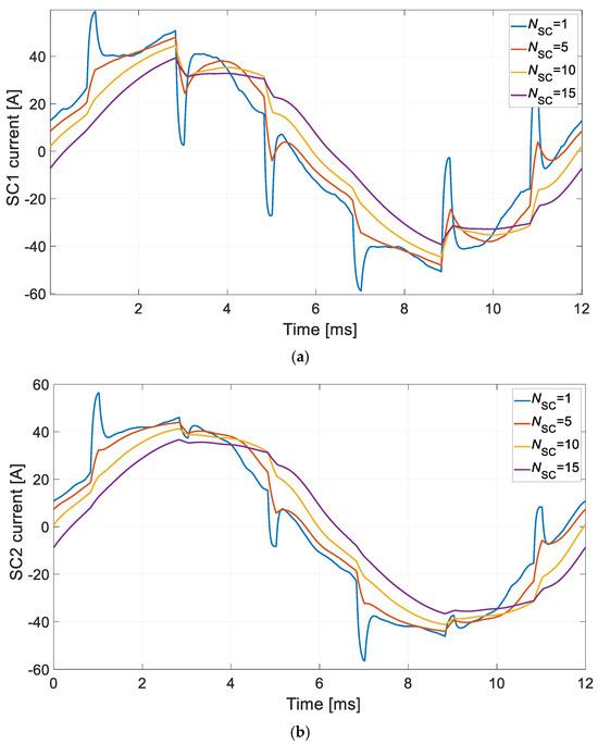
Figure 6.
SC current waveform: (a) stage of SC1, (b) stage of SC2.
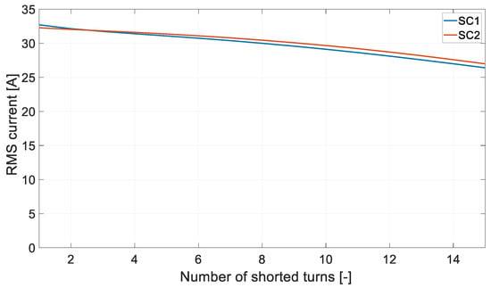
Figure 7.
RMS SC current vs. number of shorted turns Nsc.
The short-circuit current depends on the number of coils that have been shorted. It reaches its highest value when one winding is SC. This is due to the impedance of the shorted-circuit Zsc, which is as follows:
where f—frequency of current, Lsc—inductance of the short-circuited part of the winding, and Rsc—resistance of the short-circuited part of the winding. If the effects of magnetic coupling are ignored, the instantaneous value of the short-circuit current isc is determined by the following relation:
where uSC—voltage of the shorted part of the winding.
An analysis of the time courses of the obtained short-circuit currents shown in Figure 5 shows that there is a strong influence of magnetic coupling on the shape of the isc current. This is particularly evident for a single-turn short circuit (Nsc = 1). The short-circuit flux of the winding contains two components. The first comes from the permanent magnets. The second is the flux from mutual magnetic contradictions, generated mainly by the rest of the windings of the same phase. The influence of the second component clearly weakens as the number of windings increases. When the entire pole winding is short circuited, the influence of the second component is already small.
It should still be noted that identical dependencies of the RMS SC current values were not obtained for SC1 and SC2.
With a higher number of shorted turns, a higher RMS SC current value was obtained for SC2. In the case of SC1 (short circuit in the Y part), the conductor currents do not flow all the time. At SC2 (short circuit in the Δ section), the phase currents flow through the winding all the time. This generates a higher value for the second component of flux coupled to the shorted part of the winding. This increases the value of the short-circuit current.
Figure 8 shows the dependence of conductor currents (IY) and phase currents (IΔ) as a function of the number of shorted Nsc turns.
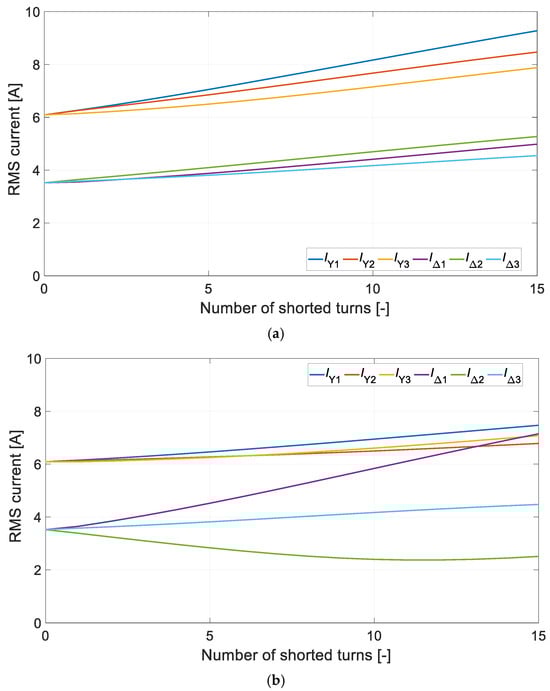
Figure 8.
RMS current vs. number of shorted turns Nsc: (a) stage of SC1, (b) stage of SC2.
As can be seen, the two SC cases have different effects. However, the SC2 condition is more damaging. It not only induces the flow of a large short-circuit current; in the rest of the shorted winding, the phase current also increases significantly. This also affects the average electromagnetic torque Teav produced by the motor (Figure 9).
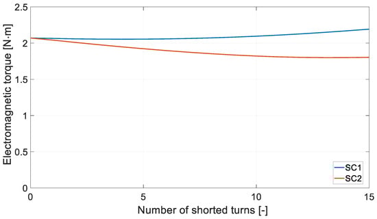
Figure 9.
Electromagnetic torque Teav vs. number of shorted turns Nsc.
In the case of SC2, there is a noticeable reduction in the value of the electromagnetic torque produced. Figure 10 shows the RMS value of the diagnostic signal.
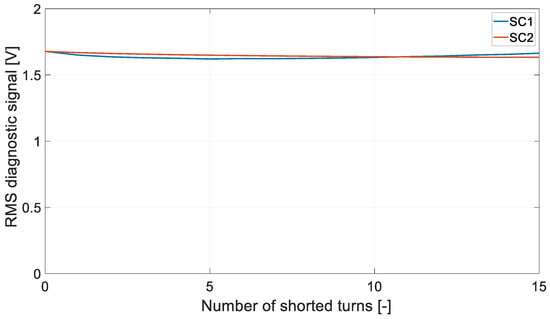
Figure 10.
RMS of diagnostic signal u0 vs. number of shorted turns Nsc.
Diagnostic information cannot be drawn from the RMS diagnostic signal u0.
5. Diagnostic Signal
An FFT analysis of the diagnostic signal u0 was performed for all the cases analysed. The characteristic frequencies of the diagnostic signal u0 such as f1, f3, f5, f7, f9, etc., were determined. Examples of harmonic content distributions are shown in the paper [22]. The harmonic amplitude was determined for each frequency. The amplitudes determined for the diagnostic signal as a function of the number of shorted turns are shown in Figure 11.
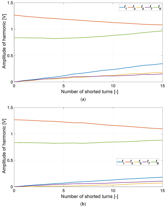
Figure 11.
Magnitude of diagnostic signal vs. number of shorted turns: (a) stage of SC1, (b) stage of SC2.
As can be seen, for a state of idle symmetry, the first, fifth, and seventh harmonics are missing. As the number of shorted Nsc coils increases, the amplitude of the first, fifth, and seventh harmonics increases. At the same time, the amplitude of the thirdrd harmonic decreases. Such trends are observed for both cases, i.e., SC1 and SC2. Increasing the number of coils decreases the difference between the amplitude of harmonic f3 and f1. This results in an increase in the amplitude of f1 relative to f3. Figure 12 shows the percentage of f1/f3.
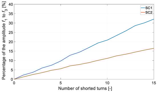
Figure 12.
Percentage of the magnitude f1/f3 vs. number of shorted turns Nsc.
The effect of partial short circuiting depends practically on the number of shorted Nsc windings. The method is more sensitive for star-connected winding configurations. In the case under consideration, the sensitivity of the method under test is approximately twice as high for SC1 as for SC2. For a state of perfect symmetry, the diagnostic harmonics f1, f5, f7, etc., are absent. In practice, obtaining such a state is not possible. Diagnostic harmonics f1, f5, and f7 will appear. However, their amplitudes should be very small.
In the case of SC2, a single-turn short circuit results in a diagnostic harmonic f1 with an amplitude of 15.9 mV. This represents 1.25% of the amplitude of the harmonic f3. For the SC1 condition for Nsc = 1, the first harmonic represents 2.3% of the f3 harmonic. Theoretically, a single-turn short-circuit condition should be detected. In this case, if the amplitude of the diagnostic harmonic f1 exceeds 1% of the amplitude of the harmonic f3, this indicates the emergence of an asymmetrical condition. An asymmetric operating condition can be caused by the inclusion of a single turn. In fact, a similar effect can be caused by the internal asymmetry of the machine, e.g., different phase resistance values.
The operation of the percentages of the harmonic amplitude ratio f1/f3 is an important indication of the condition of the BLPMM being monitored. For the monitoring and diagnosis of, for example, IM squirrel cage rotors, MCSA [23] is used. MCSA is generally based on the detection of the diagnostic harmonic f1. The amplitude of the diagnostic harmonic f1 is related to the fundamental harmonic f of the motor current. Amplitudes are given on a decibel scale. The difference between the amplitude of the fundamental harmonic f and the diagnostic harmonic f1 is important. The appearance of damage to the IM rotor winding results in a significant reduction in this difference. There are various tables that define the IM rotor condition on the basis of the value of the difference between the amplitudes. In general, a difference in less than 50 dB already indicates some deterioration in the quality of the rotor winding. A similar approach can be used to analyse the harmonics of the u0 monitoring signal. In this case, the harmonic f3 should be taken as the base harmonic. The results shown in Figure 10 are presented on a decibel scale. They are shown in Figure 13.
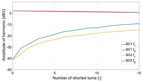
Figure 13.
Harmonic amplitudes f1 and f3 vs. number of shorted turns Nsc.
The difference in amplitude of the first and third harmonics of the diagnostic signal Δu0 is determined by the following relationship:
Figure 14 shows the calculation results obtained for both cases.
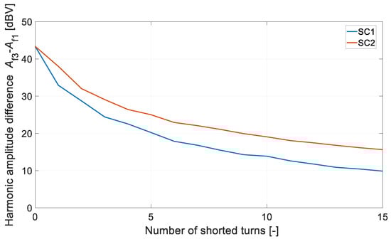
Figure 14.
The difference in amplitude f1 and f3 vs. number of shorted turns Nsc.
For the operating point analysed, a difference in Δu0 of less than 40 dBV begins to indicate an imbalance in the system operation. A difference in less than 30 dBV already indicates a significant failure (short circuit of several coils). However, the tests were carried out in a zone of limited short-circuit current influence (Figure 5). According to the authors, the developed method will detect single-winding short circuits under normal motor operating conditions (around the rated speed). Its sensitivity will decrease with low-speed operation.
To verify the possibility of detecting single-turn short circuits, additional numerical calculations were carried out. The impact of changing motor operating conditions was tested. Table 2 and Table 3 show the results obtained for several different motor operating points.
Table 2.
Impact of changing the load moment on the detectability of a single-turn short circuit.
Table 3.
Impact of rotational speed on the detectability of a single-turn short circuit.
In general, within the range of high- and medium-load torque values, the diagnostic method exhibits very similar behaviour. When operating at a low-load torque value, the difference ΔU0 increases significantly, making the method more sensitive. Simultaneously, after the appearance of damage (SC1, SC2), the value of the difference ΔU0 also increases.
Detecting SC2 short circuits (for a delta winding configuration) during low-speed operation can be challenging. However, it should be noted that the analysis considered only 0.83% of the shorted turns in the motor winding. The methods described in the articles [19,20,21] are significantly less tolerant of changes in load torque. They do not detect faults during low-speed operation with a higher proportion of shorted turns.
6. Examples of Laboratory Test Results
Laboratory verification was carried out under laboratory conditions. The waveforms of the conductor currents under symmetry conditions (Figure 15) and the two partial short-circuit winding conditions SC1 (Figure 16) and SC2 (Figure 17) were recorded for the operating point analysed.
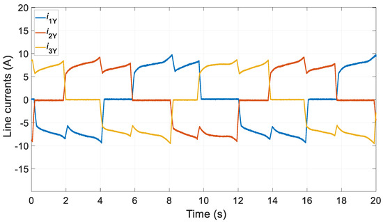
Figure 15.
Current waveforms—SYM laboratory test.
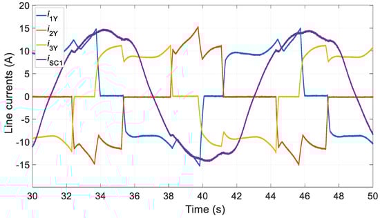
Figure 16.
Current waveforms—SC1 laboratory test.
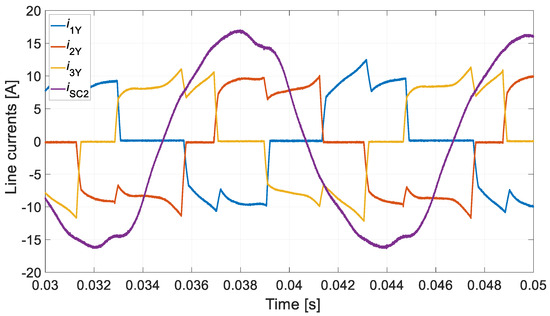
Figure 17.
Current waveforms—SC2 laboratory test.
In the laboratory tests, 30 coils (two poles) were short circuited. It is not possible to directly compare the results obtained with the laboratory tests. However, an indirect comparison is possible. The conventional symmetry condition (SYM) shown in Figure 15 is far from the theoretical assumptions. In this situation, it is difficult to expect that this will not be reflected in the diagnostic signal of the proposed method. The time courses obtained for conductor currents and short-circuit currents for SC1 and SC2 generally confirm the numerical calculations. A higher value of short-circuit current was obtained for state SC2. This is consistent with the numerical calculations (Figure 8). A higher value of the short-circuit current was obtained for the SC2 condition.
The harmonic content of the diagnostic signal u0 was determined for the states analysed. Figure 18 shows the test results obtained for the operating states analysed.
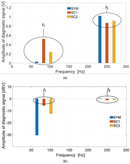
Figure 18.
FFT of diagnostic signal: (a) linear scale, (b) decibel scale.
Under real-world conditions, achieving a difference between harmonics f3 and f1 of 40 dBV is not straightforward. In the laboratory test, a difference of 30 dBV was obtained. This indicates the existence of some problems in the operation of the drive system. This is due to two problems. The first is the control asymmetry. The second problem is the asymmetry in the execution of the machine itself. Both problems are reflected in the diagnostic harmonic f1. They cause an increase in the amplitude of the harmonic f1. This affects the sensitivity of the analysed method. At the same time, the tests carried out clearly indicate that the detection of the SC2 state is more difficult (lower sensitivity of the method). This fully confirms the results of the numerical calculations.
7. Evaluation of the Monitoring and Diagnostic Method That Was Analysed
Every monitoring and diagnostic method has its advantages and disadvantages. There are no ideal solutions. According to the authors, the advantages of the analysed method include the following:
- -
- The very high sensitivity of the method;
- -
- The ability to work with any motor winding configuration;
- -
- No additional equipment is required within the motor itself;
- -
- The detection of small short circuits (less than 1% of the number of short turns);
- -
- Winding gap detection;
- -
- The detection of rotor eccentricity;
- -
- Satisfactory sensitivity of the method at very low speeds;
- -
- Only slightly changes the load torque in fault detection.
The method has the following disadvantages:
- -
- Fault detection is only possible in steady-state operation;
- -
- Recording a diagnostic signal for one electrical period is required to detect a fault;
- -
- The method has a lower sensitivity for detecting single short circuits for a delta-connected winding;
- -
- It is not possible to detect a short circuit in a power electronics transistor (shoot-through fault);
- -
- The internal asymmetry of the machine itself, along with control asymmetry, reduces the sensitivity of the method.
8. Conclusions
The diagnostic method developed by the authors for brushless permanent magnet motors was tested for sensitivity. Tests were carried out, taking into account different winding configurations, to show that a short circuit of one turn can be detected. However, this depends on the operating point of the motor and the type of winding configuration used. A greater sensitivity of the method was obtained for the detection of damage arising in the star part of the YΔ winding or the star itself. The short circuit of a one turn detection rate for a fault arising from part of a delta-connected winding is practically twice as low. This can make the detection of a single-turn short circuit impossible under certain conditions. However, the monitoring and diagnostic method developed by the authors is very sensitive. In the authors’ opinion, achieving a difference between the amplitude of the fundamental frequency (third harmonic) and the diagnostic frequency (first harmonic) of 40 dBV guarantees fully symmetrical operation. This applies both to the machine itself and the control system.
The proposed diagnostic method allows for the detection of single-turn short circuits (less than 1% of the total number of turns), even at low rotational speeds. The change in load torque does not significantly affect the sensitivity of the method. However, it should be noted that the Δ connection is more difficult to diagnose. For the Δ connection, the proposed method has a lower sensitivity in detecting single-turn short circuits. This is a certain disadvantage of the method.
The fault detection capabilities of the proposed method are much greater, e.g., it can detect rotor faults or faults in the power converter. This will be the subject of further work by the authors.
Author Contributions
Conceptualisation, M.K.; methodology, M.K. and J.P.; software, M.K.; validation, M.K., J.P. and K.R.; formal analysis, M.K.; investigation, M.K.; resources, M.K., J.P. and K.R.; data curation, M.K.; writing—original draft preparation, M.K. and K.R.; writing—review and editing, J.P.; visualisation, M.K.; supervision, J.P.; project administration, M.K.; funding acquisition, M.K. All authors have read and agreed to the published version of the manuscript.
Funding
This research received no external funding.
Data Availability Statement
The original contributions presented in the study are included in the article, further inquiries can be directed to the corresponding author.
Conflicts of Interest
The authors declare no conflicts of interest.
References
- Pajchrowski, T.; Zawirski, K. Application of Artificial Neural Network to Robust Speed Control of Servodrive. IEEE Trans. Ind. Electron. 2007, 54, 200–207. [Google Scholar] [CrossRef]
- Dianov, A.; Anuchin, A. Adaptive Maximum Torque per Ampere Control for IPMSM Drives with Load Varying over Mechanical Revolution. IEEE J. Emerg. Sel. Top. Power Electron. 2022, 10, 3409–3417. [Google Scholar] [CrossRef]
- Melfi, M.J.; Rogers, S.D.; Evon, S.; Martin, B. Permanent-Magnet Motors for Energy Savings in Industrial Applications. IEEE Trans. Ind. Appl. 2008, 44, 1360–1366. [Google Scholar] [CrossRef]
- Yang, Z.; Shang, F.; Brown, I.P.; Krishnamurthy, M. Comparative Study of Interior Permanent Magnet, Induction, and Switched Reluctance Motor Drives for EV and HEV Applications. IEEE Trans. Transp. Electrif. 2015, 1, 245–254. [Google Scholar] [CrossRef]
- Liu, C.; Chau, K.T.; Jiang, J.Z. A Permanent-Magnet Hybrid Brushless Integrated Starter–Generator for Hybrid Electric Vehicles. IEEE Trans. Ind. Electron. 2010, 57, 4055–4064. [Google Scholar] [CrossRef]
- Schiestl, M.; Marcolini, F.; Incurvati, M.; Capponi, G.C.; Stärz, R.; Caricchi, F.; Rodríguez, A.S.; Wild, L. Development of a High Power Density Drive System for Unmanned Aerial Vehicles. IEEE Trans. Power Electron. 2021, 36, 3159–3171. [Google Scholar] [CrossRef]
- González-Prieto, I.; Duran, M.J.; Rios-Garcia, N.; Barrero, F.; Martín, C. Open-switch fault detection in five-phase induction motor drives using model predictive control. IEEE Trans. Ind. Electron. 2018, 65, 3045–3055. [Google Scholar] [CrossRef]
- Xu, S.; Yu, H.; Wang, H.; Chai, H.; Ma, M.; Chen, H.; Zheng, W.X. Simultaneous Diagnosis of Open-Switch and Current Sensor Faults of Inverters in IM Drives Through Reduced-Order Interval Observer. IEEE Trans. Ind. Electron 2024. Early Access Article. [Google Scholar] [CrossRef]
- Zhao, D.; Wang, X.; Tan, B.; Xu, L.; Yuan, C.; Huangfu, Y. Fast Commutation Error Compensation for BLDC Motors Based on Virtual Neutral Voltage. IEEE Trans. Power Electron. 2021, 36, 1259–1263. [Google Scholar] [CrossRef]
- Dong, L.; Huang, Y.; Jatskevich, J.; Liu, J. Improved Fault-Tolerant Control for Brushless Permanent Magnet Motor Drives with Defective Hall Sensors. IEEE Trans. Energy Convers. 2016, 31, 789–799. [Google Scholar] [CrossRef]
- Kumar, P.H.; Somasekhar, V.T. An enhanced fault-tolerant and autoreconfigurable bldc motor drive for electric vehicle applications. IEEE J. Emerg. Sel. Top. Ind. Electron. 2023, 4, 368–380. [Google Scholar] [CrossRef]
- Aghili, F. Fault-Tolerant Torque Control of BLDC Motors. IEEE Trans. Power Electron. 2011, 26, 355–363. [Google Scholar] [CrossRef]
- Park, J.-K.; Hur, J. Detection of Inter-Turn and Dynamic Eccentricity Faults Using Stator Current Frequency Pattern in IPM-Type BLDC Motors. IEEE Trans. Ind. Electron. 2016, 63, 1771–1780. [Google Scholar] [CrossRef]
- Khan, M.A.S.K.; Azizur Rahman, M. Development and Implementation of a Novel Fault Diagnostic and Protection Technique for IPM Motor Drives. IEEE Trans. Ind. Electron. 2009, 56, 85–92. [Google Scholar] [CrossRef]
- Gupta, A.; Reddy, R.S.; Jayaraman, K. An input current-based method for fault diagnosis of high resistance connection in bldc motors. IEEE Sens. J. 2024, 24, 14844–14854. [Google Scholar] [CrossRef]
- Kim, K.-T.; Park, J.-K.; Hur, J.; Kim, B.-W. Comparison of the Fault Characteristics of IPM-Type and SPM-Type BLDC Motors Under Inter-Turn Fault Conditions Using Winding Function Theory. IEEE Trans. Ind. Appl. 2014, 50, 986–994. [Google Scholar] [CrossRef]
- Lee, S.-T.; Hur, J. Detection Technique for Stator Inter-Turn Faults in BLDC Motors Based on Third-Harmonic Components of Line Currents. IEEE Trans. Ind. Appl. 2017, 53, 143–150. [Google Scholar] [CrossRef]
- Kim, K.-H. Simple Online Fault Detecting Scheme for Short-Circuited Turn in a PMSM Through Current Harmonic Monitoring. IEEE Trans. Ind. Electron. 2011, 58, 2565–2568. [Google Scholar] [CrossRef]
- Kim, K.-T.; Lee, S.-T.; Hur, J. Diagnosis Technique Using a Detection Coil in BLDC Motors with Interturn Faults. IEEE Transac-Tions Magn. 2014, 50, 885–888. [Google Scholar] [CrossRef]
- Park, J.-K.; Jeong, C.-L.; Lee, S.-T.; Hur, J. Early Detection Technique for Stator Winding Inter-Turn Fault in BLDC Motor Using Input Impedance. IEEE Trans. Ind. Appl. 2015, 51, 240–247. [Google Scholar] [CrossRef]
- Yang, S. Online Stator Turn Fault Detection for Inverter-Fed Electric Machines Using Neutral Point Voltages Difference. IEEE Trans. Ind. Appl. 2016, 52, 4039–4049. [Google Scholar] [CrossRef]
- Korkosz, M.; Pakla, B.; Prokop, J. Frequency Analysis of Partial Short-Circuit Fault in BLDC Motors with Combined Star-Delta Winding. Energies 2022, 15, 196. [Google Scholar] [CrossRef]
- Jung, J.-H.; Lee, J.-J.; Kwon, B.-H. Online Diagnosis of Induction Motors Using MCSA. IEEE Trans. Ind. Electron. 2006, 53, 1842–1852. [Google Scholar] [CrossRef]
Disclaimer/Publisher’s Note: The statements, opinions and data contained in all publications are solely those of the individual author(s) and contributor(s) and not of MDPI and/or the editor(s). MDPI and/or the editor(s) disclaim responsibility for any injury to people or property resulting from any ideas, methods, instructions or products referred to in the content. |
© 2024 by the authors. Licensee MDPI, Basel, Switzerland. This article is an open access article distributed under the terms and conditions of the Creative Commons Attribution (CC BY) license (https://creativecommons.org/licenses/by/4.0/).