Abstract
The partial discharge (PD) measurement under pulse width modulation (PWM) voltage is a critical measurement of quality assessment for inverter-fed motors, as outlined in IEC 60034-18-41 and IEC 60034-18-42. One of the key parameters in PD measurement is the repetitive partial discharge inception voltage (RPDIV). This paper examines factors that influence the ageing process of hairpin windings in motors, with ageing tests designed using the Design of Experiment (DoE) method. The study focuses on the effects of electrical and thermal stresses on the ageing process. To achieve this, the failure rate, the RPDIV data, and the lifetime data are selected as the output responses. The findings highlights that RPDIV measurements alone cannot accurately predict the degree of ageing of hairpin windings. Specifically, RPDIV results are influenced not only by the quality of the hairpin windings under PWM voltage but also by other contributing factors. Furthermore, the change in RPDIV during the ageing process showed that the RPDIV measurement cannot predict the ageing degree of the hairpin winding. Experimental data on failure rates and lifetimes reveal that both electrical and thermal stresses significantly influence the ageing process, with a notable interaction between these factors. Among the three output responses, the failure rate provides a more accurate reflection of this interaction. To reliably estimate the lifetime of hairpin windings, more precise parameters are necessary. Further research is required to deepen the understanding of the underlying PD mechanisms under PWM voltage, which could enhance diagnostic and predictive capabilities for hairpin winding performance.
1. Introduction
The future of electric mobility is a promising one, with innovations such as electrified aircraft and autonomous driving poised to revolutionise transportation. The electric machine (EM) is one of the key components in electric mobility [1]. In recent years, there has been a remarkable trend in the production of EMs, emphasising the design of smaller yet more powerful devices with high power density. A highly effective approach to increasing power density while reducing volume is to maximise the copper content within the slot of the EM, known as the slot fill factor [2]. Rectangular windings allow high slot fill factors to be achieved in EMs. Hairpin windings, a specific type of rectangular winding employed in automotive applications [3], ensure high fill factors and are well suited to industrial automation in mass production [4].
When it comes to electric mobility, it is widely recognized that electric drives necessitate power converters with minimal rise/fall times to mitigate commutation losses. However, studies have shown that these modern pulsed voltages impose substantial electrical stresses on motor stator coils. This arises from a concentration of high electrical fields within the turn-to-turn insulation systems, as well as from transient voltages that surpass anticipated levels [5,6]. Among the different types of faults in the motor, stator winding failure is one of the leading causes of EM breakdowns [7]. Therefore, detecting early performance degradation of motor insulation is meaningful for preventive maintenance and failure avoidance.
The degradation of stator windings involves multiple factors, with the existing literature primarily focusing on electrical and thermal stress due to their substantial influence on lifetime [8,9]. Thermal stress arises from heat generated within the motor as a result of internal losses and external ambient conditions. Under normal operating conditions, thermal ageing alone does not directly cause failure; however, it progressively weakens the insulation, making it more vulnerable to additional stresses, such as electrical and mechanical forces, which ultimately lead to failure [10]. Recent studies have concentrated on predicting the lifetime of winding insulation under thermal ageing. The Arrhenius equation [11], along with an integrated approach combining the Arrhenius law and Miner’s cumulative damage theory [12], is widely employed to estimate lifetime under both constant and fluctuating temperature conditions.
In addition, while the electrical stresses on winding insulation in conventional sinusoidal-fed alternating current (AC) machines are well understood and incorporated into their design, e.g., through extensive field experience, testing, and established standards that ensure the quality and longevity of winding insulation systems [13,14], the behaviour of winding insulation systems under PWM voltage remains an ongoing area of research. With the increased use of the inverter, due to the increased dv/dt level, the turn-to-turn failures in motors have increased [15]. The electrical stress between the turns is particularly affected by both the rise time and the repetition rate. PWM voltage with a high slew rate (high dv/dt) can place additional stresses on the insulation of electromagnetic devices, potentially accelerating ageing processes [16]. Therefore, it is vital to characterise these effects to gain a full understanding of their impact on the assessment of machine insulation lifetime.
It is widely acknowledged that electrical degradation is a significant concern for insulation materials employed in electrical machines. The parameter known as RPDIV according to the IEEE standards [17,18] has been identified as a reliable indicator of the insulation condition. The RPDIV of qualified low-voltage motors has been observed to decrease with the ageing aggravation, as evidenced by the findings reported in [19]. While the impact of sinusoidal voltages on insulation ageing has been discussed in studies such as [20], the effects of PWM voltage on the RPDIV of hairpin windings—particularly over time and under varying stresses such as thermal and electrical—remain insufficiently understood. Previous results [21,22] indicate a significantly greater reduction in the RPDIV for twisted pairs subjected to steep voltage impulses from silicon carbide (SiC)-based converter impulses compared to those exposed to AC voltage waveforms. Despite this, methods to assess the quality of winding insulation systems in inverter-fed EMs are currently limited. Consequently, novel methods, such as the breakdown test [23] and weight loss test [24], are currently being investigated for the purpose of motor insulation testing.
This paper investigates the effects of electrical stress and thermal stress on the ageing of winding insulation in inverter-fed motors. The influence of factors such as temperature, voltage rise time, and amplitude was examined through systematic offline ageing tests. Thermal and electrical stresses were systematically applied using the DoE method to evaluate their influence on the RPDIV, the insulation lifetime, and the failure rate. Furthermore, the combined effects of these stresses were analyzed to better understand their interactions. Mathematical models were also employed to quantify the relationship between applied stresses and lifetime parameters.
The rest of the paper is organised as follows: Section 2 provides a detailed description of the ageing test setup and PD measurement configurations, including the circuit diagram, PD measurement methodology, and ageing procedure. Section 3 presents the measurement results and offers discussion on the effect of various stresses on the PD activity. Section 4 provides a concise introduction to the DoE method and details the measurement design based on it. The subsequent section, Section 5, discusses the individual effects and the combined effects of electrical and thermal stress. Finally, conclusions are drawn in Section 6.
2. Electrothermal Ageing Test System
The electrothermal ageing test system consists of three parts: the PWM voltage generator, temperature-controlled oven, and PD measurement system.
2.1. Device Under Test (DUT)
In order to ensure statistical significance in the investigation of the ageing mechanism or the lifetime of EMs, a large number of Device under Tests (DUTs) is required. Due to cost constraints and the necessity for a substantial number of DUTs, various emulations of the EMs insulation system have been established. Among these, the most economical option is the use of formettes, also known as hairpin-in-slot emulations. As suggested in [18], formettes are designed to represent the insulation system within a stator slot. Conversely, hairpin-in-slot emulation does not fully replicate the complex electromagnetic, thermal, and mechanical conditions of real motors. However, the focus of this paper is the fundamental ageing mechanism of the hairpin winding with polyamide-imide (PAI) insulation material. Consequently, hairpin-in-slot emulation remains a recognised methodology.
In this paper, the emulation with one hairpin in the slot was selected as the research object, shown in Figure 1. The hairpin winding placed in the slot is 30 cm long and is insulated with PAI, featuring a thickness of approximately 100 µm. The information of the DUT tested in the paper is shown in Table 1.
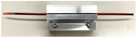
Figure 1.
An example of DUT (hairpin-in-slot emulation).

Table 1.
Parameters of the hairpin windings.
The hairpin windings from different manufacturers exhibit varying characteristics, such as differences in insulation properties. Hairpins with PAI insulation material from multiple manufacturers were evaluated in the lab. However, due to space limitations, this paper presents the results of hairpin windings from a single manufacturer and provides an analytical method for assessing the ageing of hairpin windings.
2.2. Test Platform
The electrothermal ageing test platform of the hairpin-in-slot emulation under PWM voltage is shown in Figure 2. The PWM generator is capable of generating an adjustable PWM voltage with a rise time ranging from 70 to 120 ns and a maximum voltage amplitude of 3 kV. The measurement of the PWM voltage signals was conducted by utilising a high-voltage probe connected with a 400 MHz bandwidth oscilloscope. The temperature controlled oven had a temperature setting range of 20 to 300 °C and a temperature control accuracy of 0.1 °C.
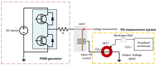
Figure 2.
Schematic diagram of the electrothermal ageing system under PWM voltage.
PD events occurring inside the DUT were measured with a high-frequency current transformer (HFCT) with a bandwidth of 10 MHz to 1 GHz. The HFCT detects interference signals, including discharge current, as well as system noise introduced by the high dV/dt of the PWM voltage. The denoising process follows the IEC 61934 standard [25]. The original signal captured by the HFCT is passed through a band-pass filter with a bandwidth of 290 MHz to 3 GHz, after which the filtered signal is denoised.
As illustrated in Figure 3, the measured pulse voltage waveform from the PWM generator (upper curve) and a typical PD signal measured by the HFCT (lower curve) are shown. It is evident from the figure that the current waveform aligns with the voltage waveform. The occurrence of PD is primarily observed at the rising and falling edges of the PWM voltage (though the falling edge is not shown, it behaves similarly to the rising edge). Furthermore, the presence of PD signals is detected during the high-level phase of the PWM voltage.
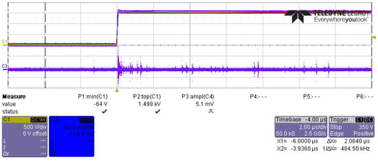
Figure 3.
Pulse voltage waveform from the PWM generator (upper curve) and PD signal (lower curve).
2.3. Parameters Settings and Test Procedures
The selection of temperature and voltage parameters was based on typical operating conditions in industrial and automotive traction motors, as well as the characteristics of the insulation material PAI. Studies have shown that winding insulation in electric motors typically experiences temperatures ranging from 40 °C to 160 °C under normal conditions and can exceed 180 °C in extreme scenarios [26]. Similarly, hairpin motors operate at rated voltages of up to 800 V, with rise times in the nanosecond range. Additionally, overvoltages may occur due to impedance mismatches, further increasing the electrical stress on the insulation. The 20 °C test condition simulates ageing at room temperature, while the 0 V test condition represents insulation ageing in the absence of electrical stress.
In order to maximise research efficiency within the available timeframe, the switching frequency was set to the highest value that could be accommodated by the experimental setup. This approach was adopted to accelerate the ageing process and to obtain meaningful degradation data within a reasonable testing duration.
In order to ensure that the test conditions closely replicated real-world environmental and electrical stresses, the selected parameters were aligned with industry standards. Furthermore, certain test conditions exceeded the rated values to evaluate the ageing process under extreme scenarios, providing valuable insights into the long-term reliability and failure mechanisms of the insulation system.
In this paper, the PWM voltage parameters were set as shown in Table 2. Ageing tests of hairpin windings were carried out at 5 different temperatures, 4 different rise times, and 6 different excitation voltage levels, resulting in a total of 20 test groups. Four DUTs were used in each test group. The test and analysis procedures were as follows:
Table 2.
PWM voltage parameters and temperature parameters.
- Referring to the IEC 60031-18-42, the RPDIV of 5 hairpin-in-slot emulations was tested under the different temperatures (20–180 °C).
- RPDIV measurements were performed on each DUT before the ageing process. The RPDIV measurements were carried out in the same environment as the ageing process.
- The ageing process was carried out on 4 DUTs for each test group. These 4 DUTs were divided into 2 groups, Group A and Group B. The RPDIV measurements were performed on Group A DUTs every 24–96 h. For Group B DUTs, the RPDIV measurements were performed at the beginning and at the end of the process. The RPDIV measurement was repeated 10 times. The total ageing time was ≥250 h.
- W established quantitative mathematical relationship equations between the lifetime of the hairpin winding and the influencing factors.
3. Introduction of DoE Method and Measurement Design for Combined Effect Analysis
The DoE is a systematic approach to experimentation in which a set of input variables, or factors, are intentionally varied to observe and identify their effects on the output response [27].
In experimental design, the controllable input variables to the ageing process (in this case, the temperature or the voltage amplitude) are the factors. The output of the experiment is called the response. The polynomial equation often used to model the response variable (Y) as a function of the input factors (X’s) is
where is the overall mean response; indicates the main effect of each factor (); denotes the interaction effect between the ith and jth factors, and denotes the three-way interaction effect among the ith, jth, and kth factors.
In the context of screening experiments, each factor is typically characterised by two levels, designated as “high” and “low”, and assigned the values +1 and −1, respectively. The utilisation of solely two levels suggests that the effects are monotonic on the response variable, though necessarily linear. Interaction between factors occurs when the effect of one factor on the response variable depends on the level of another factor. When plotting the response means for the 4 combinations of high and low levels of the 2 factors, this interaction is represented by two non-parallel lines, as illustrated in Figure 4.
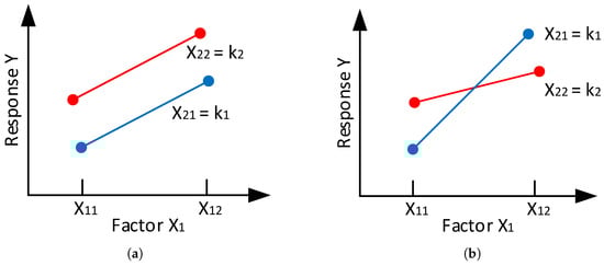
Figure 4.
Schematic of the absence or presence of a two-factor interaction. (a) No interaction of factors and , (b) Interaction of factors and .
Three factors have already been identified for the ageing process: temperature, excitation voltage amplitude, and the rise time. A full factorial experiment with three factors consists of treatment combinations. The two levels chosen for each input variable were controlled by the ageing test and are shown in Table 3.
Table 3.
The classification of value of the parameter for the design for the two-factor scenario.
The analysis of material ageing is dependent on critical parameters, including RPDIV data, insulation lifetime, and failure rate. The insulation lifetime is defined as the time at which a breakdown occurs in the hairpin winding, while failure rate represents the percentage of DUTs that experience breakdown during the ageing process. The three output responses are analyzed using an experimental matrix that encompasses all possible combinations of two levels for each of the three input factors: temperature, excitation voltage amplitude, and rise time, as detailed in Table 3.
To analyze the influence of the single factor and the combined effect of multiple factors, statistical methods are employed to analyze the experimental data as follows:
- Linear regression analysis is used to establish the relationship between ageing time and the RPDIV at specific excitation voltage and temperature. The ageing rate of the material is compared based on the slope of the linear regression;
- Based on the classification of the parameters, the average corresponding response at the “−” and “+” levels was calculated. The difference in average response denotes the influence of a single parameter as it increases from the “low” level to the “high” level;
- To assess the combined effect of multiple parameters, an interaction plot is used to visualize the interaction between two factors of interest.
4. Results
4.1. RPDIV Under Different Temperature and Rise Time
The variation of RPDIV with temperature and rise time is shown in Figure 5. It can be seen that RPDIV tends to increase as the rise time increases. The influence of the increasing temperature on RPDIV is more significant than the rise time. The difference between the maximum and minimum values of RPDIV at room temperature for different rise times is about 200 V, while at higher temperatures, such as 180 °C and 80 °C, the difference exceeds 400 V. This suggests that PD events are more easily triggered at higher temperatures. To ensure that the ageing of the hairpin winding takes place under the electrical and thermal stresses, the excitation voltage in the electrothermal ageing test is chosen below RPDIV.
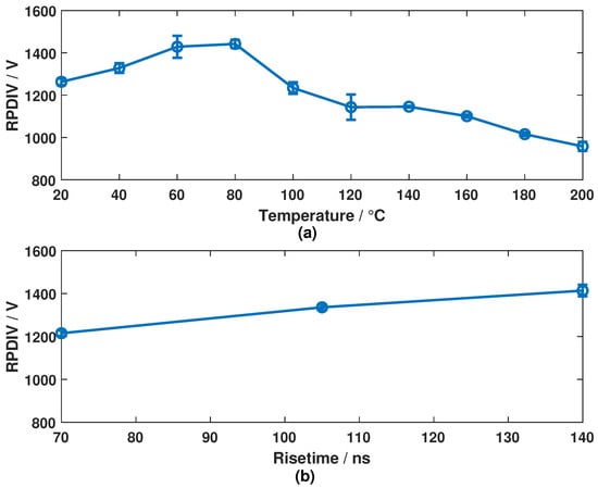
Figure 5.
Variation of RPDIV (mean value ± standard deviation) with different (a) temperature (b) rise time.
4.2. Influence of PD Measurements on Ageing of Hairpin Winding
The present study identifies the occurrence of PD events as a critical factor in the degradation of insulation [28]. A key aspect of the investigation is determining whether PD measurement itself could potentially accelerate the degradation process. It is imperative to comprehend this relationship to ensure the accuracy and reliability of ageing tests. The failure rates of the Group A and Group B DUTs are presented in Table 4.
Table 4.
Failure rate of Group A and Group B DUTs in ageing test.
The statistics presented in Table 4 reveal that the failure rate remains largely unaffected by the PD measurements during the ageing process. Given the inherent variation among the DUTs, a 10% difference is considered reasonable. The present study focuses on Group A DUTs, which provide more extensive PD measurement data compared to Group B DUTs.
4.3. Ageing of Hairpin Winding Under Different Temperature
According to the IEC 61858 standard [29], the lifetime of hairpin windings at different temperatures can be modeled using a regression curve. Once lifetime data at a specific temperature are obtained, the regression curve can be used to predict the lifetime at other temperatures. This relationship is expressed in Equation (2):
where is the correlation time and is defined as
where M is the slope of the regression equation (also the slope of the reference life model); is the ageing temperature corresponding to the reference life data [°C]; is the ageing temperature of the predicted life data [°C]; denotes the relative thermal endurance index of the insulation system [°C]; is the reference lifetime [h]; and is the predicted lifetime according to the regression curve [h].
The results of the RPDIV measurements as a function of ageing time at different temperatures are shown in Figure 6. In order to facilitate comparison of the change in RPDIV value at different temperatures and to normalise the RPDIV values, the relative RPDIV value is employed. The relative RPDIV is defined as follows:
where is the time before the ageing process begins, and is the specific ageing time at which the RPDIV is measured.
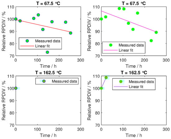
Figure 6.
RPDIV data of hairpin windings under different temperature (under same electrical stress).
In Figure 6, the solid dots represent the average measured RPDIV values, calculated as the mean of 10 individual RPDIV values, while the curve represents the linear regression fit of RPDIV values against ageing time. Each row corresponds to results from two different DUTs subjected to the same ageing test. An ageing time of less than 250 h indicates the failure of the DUT during the ageing process. For example, in the bottom subplot at 162.5 °C, the DUTs failed during the ageing process, resulting in only one recorded RPDIV measurement. In such cases, the regression method cannot be applied effectively.
As demonstrated in Figure 6, the lifetime of the DUTs is observed to decrease with increasing temperature, under constant electrical stress conditions. A comparison of Figure 5 and Figure 6 reveals that temperature exerts a consistent influence on RPDIV, paralleling its effect on the hairpin winding’s lifetime. It is evident that an increase in temperature leads to a reduction in both the RPDIV and the lifetime of the hairpin winding. However, it should be noted that the RPDIV measurements deviate from the fitted regression curve. For instance, at 162.5 °C, the RPDIV exhibits an increase before the failure happened. This finding indicates that while PD measurements can assess the condition of the insulation system, a reduction in RPDIV for an inverter-fed motor does not necessarily directly correlate with a decrease in the remaining lifetime.
4.4. Ageing of Hairpin Winding Under Different Excitation Voltage
When analyzing the influence of the amplitude of the voltage, the excitation voltage is higher than the rated voltage of the hairpin winding to analyse the effect of overvoltages. The RPDIV test data and linear fitted curves are shown in Figure 7. The thermal stress is the same for all the tests shown in Figure 7 (T = 67.5 °C). Under this thermal stress, the electrical stress ranges from 0 to 975 V (the rated voltage of the hairpin winding is 800 V) with the same rise time.
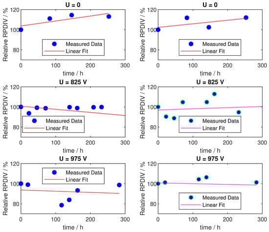
Figure 7.
RPDIV data of hairpin windings under different excitation voltage (same rise time, under same thermal stress).
The subplots in each row represent the RPDIV results of two different DUTs in Group A subjected to the same ageing test. As demonstrated, the RPDIV results occasionally exhibit differing trends within the same test. For instance, in the test with an excitation voltage of 825 V (second row in Figure 7), the RPDIV of one DUT decreases after 300 h (left subplot), while for the other, it increases (right subplot).
Comparing the subplots on the left side and the right side, the trends of change in the RPDIV value with increasing excitation voltage are different. On the left side, as the excitation voltage increases from 0 to 825 V, the rate of decrease of RPDIV accelerates. However, as the voltage continues to increase 975 V, the rate of decline slows. In contrast, the subplots on the right side show an increasing rate of RPDIV decline as the excitation voltage increases.
Conversely, increasing the excitation voltage did not lead to breakdowns during the ageing test, as no premature failures were observed. The RPDIV behaviour exhibited irregular fluctuations over time, suggesting that factors other than ageing influence RPDIV behaviour. Consequently, changes in RPDIV alone may not be a reliable indicator of ageing in hairpin windings under PWM voltage.
4.5. Ageing of Hairpin Winding Under Different Rise Time
The RPDIV is influenced by the rise time of the applied voltage signal, as illustrated in Figure 5. This section compares the ageing behaviour under different rise times. Figure 8 presents the RPDIV data and their corresponding fitted curves for various rise times. To ensure consistent overvoltage levels across different rise times, a 5 m two-wire cable was placed between the PWM generator output and the DUT. As shown in Figure 8, increasing the rise time from 70 ns to 120 ns has minimal impact on the rate of decline in RPDIV or the occurrence of early breakdowns. Consequently, rise time is not considered a significant factor in analyzing the ageing mechanism of the hairpin winding in this study.
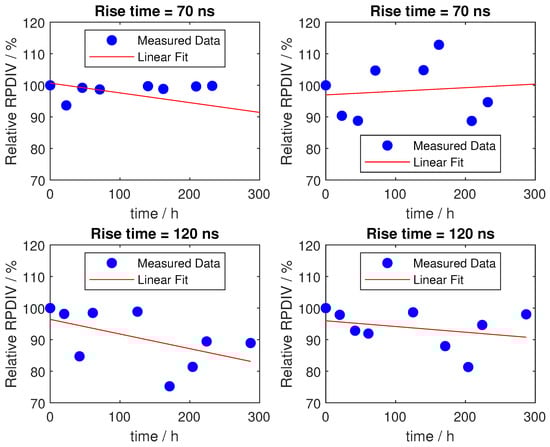
Figure 8.
RPDIV data of hairpin windings under different voltage rise time (same voltage level, under same thermal stress).
5. Discussion
Gian Carlo Montanari introduced an electrothermal lifetime model for solid insulating materials subjected to repetitive pulsed voltages [30]. The model delineates the relationship between the lifetime and the temperature T and the pulsed electric field E. This relationship is elucidated in Equation (5):
where A is the model parameter to be determined, is the activation energy in the electrothermal ageing process, K is the Boltzmann constant, E is the equivalent electrical ageing term, and E/T is the synergistic term.
Taking the logarithm of Equation (6), the following expression is obtained:
As demonstrated in (6), the lifetime is found to be contingent on the electric field E (in the absence of PD during the ageing process) at a constant temperature T. For a constant excitation voltage amplitude U and a given DUT (with the same electric field structure, where the electric field inhomogeneity coefficient f is constant), the electric field E is given by E = f (U/d). This relationship indicates that E remains constant, suggesting that the lifetime should also remain unchanged for the same voltage amplitude.
The main reason for the fluctuation of the PD may be the effect of the residual electric field caused by the PD activity under unipolar square waves [31]. Fabiani et al. pointed out that the electric field in the air gap between two wires under square wave voltage is influenced not only by the applied voltage but also by the residual electric field after the PD happens. Therefore, the factors governing PD activity are not only the amplitude of the applied voltage but also the residual electric field. However, there are currently no quantitative expressions for calculating the residual electric field, making it difficult to analyse its effect quantitatively.
5.1. Combined Effect of Temperature and Voltage Amplitude on Ageing of Hairpin Winding
The results presented in Section 4 demonstrate that the rise time of the PWM voltage exerts negligible influence on the ageing of hairpin windings. This finding is consistent with the conclusion drawn from Equation (6), which indicates that the lifetime of solid insulation material is influenced primarily by the combined effects of temperature and electric field strength (proportional to the voltage amplitude, E = f (U/d)). Consequently, the analysis of combined effects in this paper focuses exclusively on the interaction between temperature and voltage amplitude.
As the rise time is not considered in the combined effect analysis, there are only combinations of input parameters. The relative RPDIV data are analysed after 250 h of ageing. To assess the individual effects of the input parameters (voltage amplitude and temperature) on the output variables (relative RPDIV, lifetime, and failure rate), the average outputs at the “low” (−1) and “high” (+1) levels are calculated, as explained in Table 3. These averages are derived from the data collected to represent the impact of each parameter at its respective level. The results are presented in a bar chart, as shown in Figure 9.
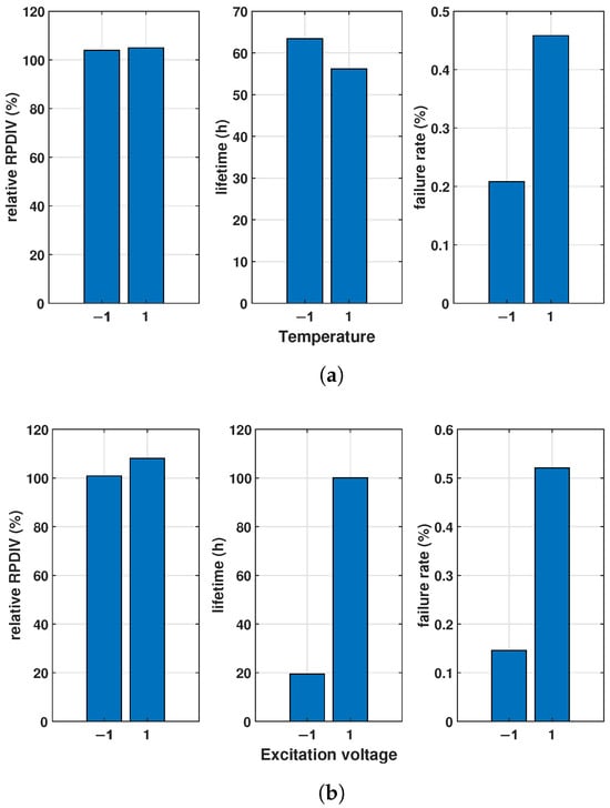
Figure 9.
Main effect diagram of (a) temperature and (b) excitation voltage on RPDIV, lifetime, and failure rate.
As demonstrated in Figure 9, it is evident that an increase in temperature from “low level” to “high level” results in a concomitant rise in the change in relative RPDIV. It is noteworthy that the relative RPDIV exceeds 100% at the end of the ageing process, indicating an increase compared to the initial RPDIV. This observation is consistent with the discussion in Section 3 and may be attributed to the influence of additional factors on the RPDIV.
In contrast, the other two outputs show opposite trends: the lifetime increases, while the failure rate decreases as the temperature rises to the “high level”. These results suggest that elevated temperatures accelerate the insulation ageing process of the hairpin winding. However, the changes in the relative RPDIV data do not directly support this conclusion.
In Figure 9b, the effect of excitation voltage amplitude is analyzed. The results show that all three outputs have an increasing trend as the excitation voltage increases from “low level” to “high level”. This behaviour contradicts the prediction of Equation (6). The discrepancy may be due to variations in the insulation quality of the DUTs, with failures resulting from these differences rather than the ageing process itself. To address this issue, if lifetime were used as the evaluation parameter, the ageing process would need to continue until all DUTs had failed, requiring a longer test duration.
The failure rate is probably the most reliable indicator of the influence of temperature and voltage amplitude of the three parameters. The results show that the ageing of hairpin windings is accelerated by increasing both the temperature and the voltage amplitude.
The combined effect of the temperature and the voltage amplitude is discussed using interaction plots for the relative RPDIV, the lifetime, and the failure rates. Interaction plots for the relative RPDIV, the lifetimes of failed DUTs, and the failure rates are shown in Figure 10, Figure 11 and Figure 12, respectively.
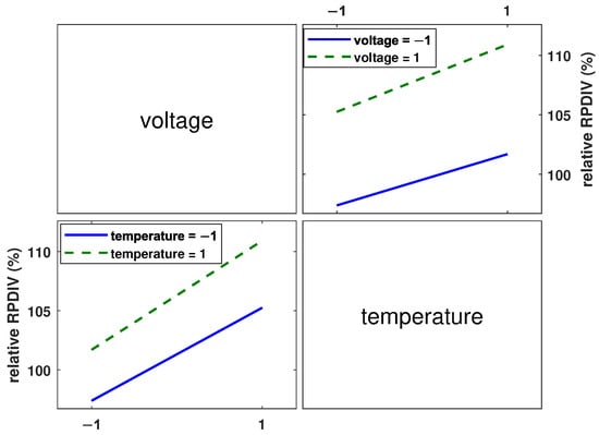
Figure 10.
Interaction plot for relative RPDIV.
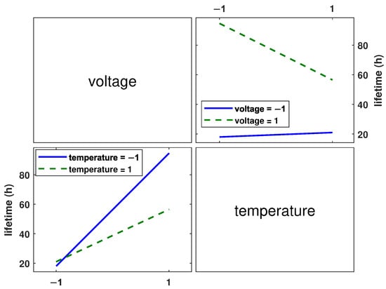
Figure 11.
Interaction plot for lifetime of DUTs.
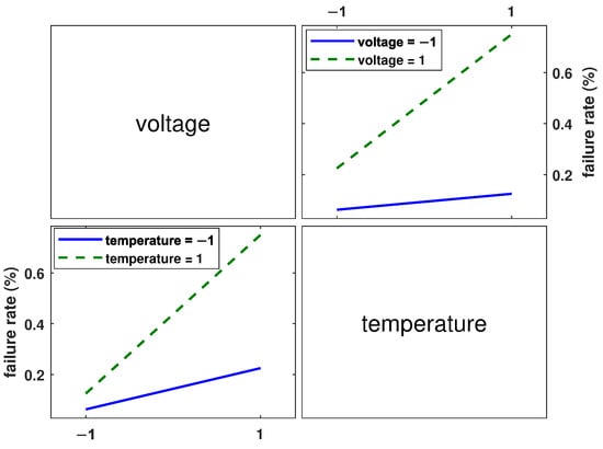
Figure 12.
Interaction plot for failure rate.
In Figure 10, the two plotted lines are nearly parallel, indicating that no significant interaction between temperature and excitation voltage is observed when the relative RPDIV is used as the response. However, in Figure 11 and Figure 12, the plotted lines are not parallel, indicating that there is an interaction between excitation voltage and temperature when failure rate and lifetime are considered as responses.
Specifically, Figure 11 demonstrates that the intersection of the lines signifies a reversal of the effect of temperature as a function of excitation voltage level when lifetime is utilised as the response. Specifically, at the “high level” of voltage, the lifetime decreases as the temperature increases from low to high. Conversely, at the “low level” of voltage, an increase in lifetime is observed as temperature increases from “low level” to “high level”. Furthermore, at both low and high temperature levels, an increase in lifetime is observed as the excitation voltage level is increased from low to high.
Figure 12 demonstrates that the effect of temperature on failure rate depends on the level of excitation voltage, as indicated by the divergence of the lines. The impact of temperature on failure rate is more pronounced at higher voltage levels, as indicated by the steeper slope of the corresponding line. Similarly, the effect of excitation voltage varies with the temperature level, with the impact of voltage on failure rate being more pronounced at higher temperature levels.
The combined effect of temperature and excitation voltage appears to vary depending on the chosen output response, although they are all used as an indicator of ageing. According to Equation (6), an interaction between the electric field (excitation voltage) and temperature is expected when considering lifetime or degradation. However, the analysis of the relative RPDIV data does not reveal any significant interaction. In addition, the predicted outcome of Equation (6) is that an increase in both the electric field and temperature should result in a decrease in the lifetime of the insulation system. However, Figure 11 does not demonstrate this trend. Of the three responses, only the failure rate aligns with the predictions of Equation (6).
5.2. Discussion of Inconsistency of Result
The inconsistency between the measured lifetime data and the prediction of Equation (6) may be due to the limited ageing time and the limited quantity of the DUTs. When no failures occur during the ageing process, it becomes impossible to accurately determine the lifetime. In addition, the lifetime of the DUT is influenced by individual differences in quality. With an insufficient number of DUTs, the lifetime data lack statistical reliability, further contributing to the discrepancy.
The study was conducted on a limited number of DUTs, which impacts the generalisability of the results. Due to cost and time constraints, only four DUTs per test condition were used, which may not fully capture the variability in manufacturing defects or material inconsistencies across a larger population of DUTs. Future studies should include a larger sample size to improve statistical confidence and allow for more robust conclusions regarding insulation ageing behaviour.
The ageing tests were conducted over approximately 250 h, which may not fully reflect the long-term performance of insulation systems in real-world scenarios. In practice, insulation degradation occurs over thousands of hours. Future studies should aim to extend the duration of ageing tests to better assess the long-term failure mechanisms and provide more reliable lifetime predictions.
The variability in RPDIV data observed in this study can be attributed to several interdependent factors. While a general decrease in RPDIV is expected due to insulation degradation, occasional increases in RPDIV suggest changes in the insulation system. Several mechanisms may explain this phenomenon:
- Surface charge accumulation and redistribution: During ageing, the applied PWM voltage can lead to surface charge accumulation on the insulation material. In some cases, this accumulated charge temporarily increases the apparent RPDIV, delaying the onset of PDs [32].
- Modification of the insulation microstructure: Prolonged exposure to thermal and electrical stress can induce molecular reorganization or oxidation in the insulation material, potentially altering its permittivity and thickness. These changes can temporarily improve the dielectric strength, resulting in an increase in RPDIV. However, as the degradation progresses, these effects are usually reversed [23,33,34].
- Localised curing or densification effects: The PAI insulation material undergoes complex ageing mechanisms, including thermally and electrically induced crosslinking. In certain conditions, this could lead to localised densification, temporarily enhancing insulation properties and leading to an increase in RPDIV. However, this effect is often non-uniform and diminishes as cracks and voids form over time [35].
The present study has determined that elevated temperatures and high excitation voltage amplitudes accelerate the ageing process of the insulation in hairpin windings. However, the prevailing trend in the development of electric motors is towards higher power density, which in turn results in increased motor temperatures. In order to mitigate excessive heat, it is necessary to reduce the motor current, which consequently leads to higher insulation voltage. The only viable solutions to counteract high temperatures and high excitation voltages are improving the system’s heat dissipation capabilities or developing new insulation materials with superior electrical properties.
On the other hand, if a hairpin winding or an electric motor with insulation material undergoes ageing due to elevated temperatures and PWM voltage, the results of this research indicate that PD measurements may not accurately reflect the motor’s ageing state. Consequently, new measurement techniques or parameters must be proposed in order better predict the motor’s lifetime. A deeper understanding of the PD mechanisms under PWM conditions is essential to provide more accurate insights into the insulation’s state of the hairpin winding under PWM voltage.
6. Conclusions
It has been documented that the increased temperatures and PWM voltage can expedite the degradation of the ageing of hairpin windings in electric motors. Conventionally, ageing tests have been conducted using the 50 Hz sinusoidal voltage. This paper aims to analyse the ageing of hairpin windings under PWM voltage. Through a series of experiments, the efficacy of the proposed ageing test setup and the test plan, based on the DoE method, in facilitating PD measurements, simulating the ageing process of hairpin windings, and collecting data for evaluation, has been demonstrated.
The experimental findings demonstrated show that PD measurements in the ageing process did not result in a substantial increase in failure rates, providing a robust foundation for the ageing test approach. In the tests, both increased temperatures and increased excitation voltage amplitudes were observed to accelerate the ageing of the hairpin windings, as evidenced by the increased failure rate. However, the changes in relative RPDIV were not significant, and the lifetime data did not align with theoretical predictions. The interaction plot demonstrated an interaction between temperature and voltage amplitude, whereby the failure rate and lifetime were used as the output variables. These results further substantiate the effect of temperature and excitation voltage amplitude on the ageing of hairpin windings, thereby contributing to a more comprehensive understanding of the ageing mechanism under PWM voltage.
The present study indicates the necessity of updating standard testing procedures. PD measurement alone may not be sufficient to assess the insulation condition under PWM voltage and should be complemented by additional parameters. The study demonstrates that the process of insulation ageing is affected by the combined effect of thermal and electrical stress. Therefore, it is recommended that standardised ageing protocols consider the effects of temperature–voltage interaction to ensure accurate lifetime predictions for inverter-fed motors. Subsequent research should consider additional influencing factors, such as humidity and switching frequency, when evaluating combined effects.
The results indicate that RPDIV under PWM voltage is influenced not only by the insulation state of the hairpin windings but also by other parameters during the ageing process, potentially linked to surface charge effects and variations in insulation thickness. Further in-depth research is needed to better understand PD mechanisms under PWM voltage, as this could serve as an early diagnostic indicator of hairpin degradation.
Additionally, developing a reliable lifetime model for hairpin windings will require further investigation to identify suitable parameters and enhance the understanding of the ageing process. Alternative diagnostic methods should be explored for a more accurate assessment of insulation ageing. Promising approaches include dielectric loss and dissipation factor () measurements and the electrical treeing and breakdown test.
Furthermore, future studies should incorporate the effects of humidity and switching frequency to provide a more comprehensive understanding of insulation ageing. By combining PD measurements with other diagnostic techniques, a hybrid model could be developed to assess insulation system health more reliably.
Author Contributions
Conceptualization, M.B. and S.T.; methodology, C.H.; software, C.H.; validation, C.H.; formal analysis, C.H. and M.B.; writing—original draft preparation, C.H.; writing—review and editing, C.H., M.B. and S.T.; supervision, M.B. and S.T.; funding acquisition, M.B. and S.T. All authors have read and agreed to the published version of the manuscript.
Funding
The research leading to this work is being carried out as part of the project “Lebensdauermodell Wicklungsisolation” (IGF-Nr. 21658N) and is supported by the Federal Ministry for Economic Affairs and Climate Action.
Data Availability Statement
The datasets presented in this article are not readily available because the data are part of an ongoing study.
Conflicts of Interest
The authors declare no conflicts of interest.
Abbreviations
The following abbreviations are used in this manuscript:
| PWM | Pulse Width Modulation |
| RPDIV | Repetitive Partial Discharge Inception Voltage |
| DoE | Design of Experiment |
| PD | Partial Discharge |
| EM | Electric Machine |
| SiC | Silicon Carbide |
| AC | Alternating Current |
| DUT | Device under Test |
| PAI | Polyamide-imide |
| HFCT | High-Frequency Current Transformer |
| ANOVA | ANalysis of VAriance |
References
- Bonnett, A.H.; Yung, C. Increased Efficiency Versus Increased Reliability. IEEE Ind. Appl. Mag. 2008, 14, 29–36. [Google Scholar] [CrossRef]
- Makita, S.; Ito, Y.; Aoyama, T.; Doki, S. The proposal of a new motor which has a high winding factor and a high slot fill factor. In Proceedings of the 2014 International Power Electronics Conference (IPEC-Hiroshima 2014–ECCE ASIA), Hiroshima, Japan, 18–21 May 2014; pp. 3823–3827. [Google Scholar] [CrossRef]
- Arzillo, A.; Nuzzo, S.; Braglia, P.; Franceschini, G.; Barater, D.; Gerada, D.; Gerada, C. An Analytical Approach for the Design of Innovative Hairpin Winding Layouts. In Proceedings of the 2020 International Conference on Electrical Machines (ICEM), Gothenburg, Sweden, 23–26 August 2020; Volume 1, pp. 1534–1539. [Google Scholar] [CrossRef]
- Zhao, Y.; Li, D.; Pei, T.; Qu, R. Overview of the rectangular wire windings AC electrical machine. CES Trans. Electr. Mach. Syst. 2019, 3, 160–169. [Google Scholar] [CrossRef]
- Sedding, H.; Chan, C.; Sasic, M.; Stone, G. Assessment of Stator Winding Insulation Condition Based on Absolute Partial Discharge Magnitude. In Proceedings of the 2023 INSUCON—14th International Electrical Insulation Conference (INSUCON), Birmingham, UK, 18–20 April 2023; pp. 19–23. [Google Scholar]
- Grubic, S.; Aller, J.M.; Lu, B.; Habetler, T.G. A Survey on Testing and Monitoring Methods for Stator Insulation Systems of Low-Voltage Induction Machines Focusing on Turn Insulation Problems. IEEE Trans. Ind. Electron. 2008, 55, 4127–4136. [Google Scholar] [CrossRef]
- Mancinelli, P.; Stagnitta, S.; Cavallini, A. Qualification of Hairpin Motors Insulation for Automotive Applications. IEEE Trans. Ind. Appl. 2017, 53, 3110–3118. [Google Scholar] [CrossRef]
- Madonna, V.; Giangrande, P.; Lusuardi, L.; Cavallini, A.; Gerada, C.; Galea, M. Thermal Overload and Insulation Aging of Short Duty Cycle, Aerospace Motors. IEEE Trans. Ind. Electron. 2020, 67, 2618–2629. [Google Scholar] [CrossRef]
- Mancinelli, P.; Stagnitta, S.; Cavallini, A. Lifetime analysis of an automotive electrical motor with hairpin wound stator. In Proceedings of the 2016 IEEE Conference on Electrical Insulation and Dielectric Phenomena (CEIDP), Toronto, ON, Canada, 16–19 October 2016; pp. 877–880. [Google Scholar] [CrossRef]
- Mirafzal, B.; Skibinski, G.L.; Tallam, R.M. A Failure Mode for PWM Inverter-Fed AC Motors Due to the Antiresonance Phenomenon. IEEE Trans. Ind. Appl. 2009, 45, 1697–1705. [Google Scholar] [CrossRef]
- Han, C. Lifetime evaluation of class E electrical insulation for small induction motors. IEEE Electr. Insul. Mag. 2011, 27, 14–19. [Google Scholar] [CrossRef]
- Hirose, H.; Sakumura, T. Foundation of mathematical deterioration models for the thermal stress. IEEE Trans. Dielectr. Electr. Insul. 2015, 22, 482–487. [Google Scholar] [CrossRef]
- Stone, G.; Boulter, E.; Culbert, I. Electrical Insulation for Rotating Machines: Design, Evaluation, Aging, Testing, and Repair; Institute of Electrical and Electronics Engineers, Inc.: Piscataway, NJ, USA, 2004. [Google Scholar] [CrossRef]
- IEEE Std 522-2004; IEEE Guide for Testing Turn Insulation of Form-Wound Stator Coils for Alternating-Current Electric Machines. IEEE: Piscataway, NJ, USA, 2004; pp. 1–28. [CrossRef]
- Cavallini, A.; Fabiani, D.; Montanari, G.C. Power electronics and electrical insulation systems—Part 2: Life modeling for insulation design. IEEE Electr. Insul. Mag. 2010, 26, 33–39. [Google Scholar] [CrossRef]
- Wang, P.; Montanari, G.C.; Cavallini, A. Partial Discharge Phenomenology and Induced Aging Behavior in Rotating Machines Controlled by Power Electronics. IEEE Trans. Ind. Electron. 2014, 61, 7105–7112. [Google Scholar] [CrossRef]
- IEC 60034-18-41; Rotating Electrical Machines—Part 18-41: Partial Discharge Free Electrical Insulation Systems (Type I) Used in Rotating Electrical Machines Fed from Voltage Converters—Qualification and Ality Control Tests. IEC: Geneva, Switzerland, 2014.
- IEC 60034-18-42. Rotating Electrical Machines—Part 18–42: Qualification and Acceptance Tests for Partial Discharge Resistant Electrical Insulation Systems (Type II) Used in Rotating Electrical Machines Fed from Voltage Converters. IEC: Geneva, Switzerland, 2017.
- Stone, G.C.; Campbell, S.R.; Sedding, H.G. Characteristics of noise and interphasal PD pulses in operating stator windings. In Proceedings of the 2011 Electrical Insulation Conference (EIC), Annapolis, MD, USA, 5–8 June 2011; pp. 15–19. [Google Scholar] [CrossRef]
- Szczepanski, M.; Fetouhi, L.; Sabatou, M.; Dreuilhe, S.; Pin, S.; Van de Steen, C.; Belijar, G. How does PDIV change during isothermal aging of magnet wire. In Proceedings of the 2022 IEEE Electrical Insulation Conference (EIC), Knoxville, TN, USA, 19–23 June 2022; pp. 266–271. [Google Scholar] [CrossRef]
- Rumi, A.; Cavallini, A.; Marinelli, J. The Impact of Impregnating Resins in Ensuring the Reliability of Inverter-Fed Machines. In Proceedings of the 2020 International Symposium on Electrical Insulating Materials (ISEIM), Tokyo, Japan, 13–17 September 2020; pp. 253–256. [Google Scholar]
- Sundeep, S.; Wang, J.; Griffo, A.; Alvarez-Gonzalez, F. Peak Voltage Stress on Stator Winding in PWM Inverter fed Drives. In Proceedings of the 2020 International Conference on Electrical Machines (ICEM), Gothenburg, Sweden, 23–26 August 2020; Volume 1, pp. 1579–1585. [Google Scholar] [CrossRef]
- Zeynalova, S.; Cepparrone, E.; Roffino, E.; Barbero, D. Effect of Thermal Aging on Electrical Performance of Perfluoroalkoxy- and Polyamide-Imide-Coated Magnet Wire. IEEE Electr. Insul. Mag. 2024, 40, 6–14. [Google Scholar] [CrossRef]
- De Vivo, B.; Lamberti, P.; Raimo, R.; Tucci, V.; Vertuccio, L.; Beneduce, L. Effects of thermo-electrical aging on the properties of epoxy-based nanocomposites for motor insulation. In Proceedings of the 2015 IEEE 10th International Symposium on Diagnostics for Electrical Machines, Power Electronics and Drives (SDEMPED), Guarda, Portugal, 1–4 September 2015; pp. 226–231. [Google Scholar] [CrossRef]
- IEC 61934; Electrical Insulating Materials and Systems—Electrical Measurement of Partial Discharges (PD) Under Short Rise Time and Repetitive Voltage Impulses. IEC: Geneva, Switzerland, 2011.
- IEEE Std 1349-2021; IEEE Guide for the Application of Electric Machines in Zone 2 and Class I, Division 2 Hazardous (Classified) Locations. IEEE: Piscataway, NJ, USA, 2021; pp. 1–211. [CrossRef]
- Verseput, R. Digging into DOE Selecting the right central composite design for response surface methodology applications. Qual. Dig. 2001, 21, 33–36. [Google Scholar]
- Lévesque, M.; Hudon, C.; David, E. Insulation degradation analysis of stator bars subjected to slot partial discharges. In Proceedings of the 2013 IEEE Electrical Insulation Conference (EIC), Ottawa, ON, Canada, 2–5 June 2013; pp. 479–483. [Google Scholar] [CrossRef]
- IEC 61858; Electrical Insulation Systems—Thermal Evaluation of Modifications to an Established Electrical Insulation System (EIS)—Part 1: Wire-Wound Winding EIS. IEC: Geneva, Switzerland, 2014.
- Montanari, G.C. Time behavior of partial discharges and life of type II turn insulation specimens under repetitive impulse and sinusoidal waveforms. IEEE Electr. Insul. Mag. 2017, 33, 17–26. [Google Scholar] [CrossRef]
- Fabiani, D.; Montanari, G.; Cavallini, A.; Mazzanti, G. Relation between space charge accumulation and partial discharge activity in enameled wires under PWM-like voltage waveforms. IEEE Trans. Dielectr. Electr. Insul. 2004, 11, 393–405. [Google Scholar] [CrossRef]
- Fabiani, D.; Cavallini, A.; Mazzanti, G.; Montanari, G. The effect of charge mobility on partial discharge characteristics of enamelled wires for PWM-controlled motors. In Proceedings of the Proceedings of the 2004 IEEE International Conference on Solid Dielectrics, 2004. ICSD 2004, Toulouse, France, 5–9 July 2004; Volume 2, pp. 856–859. [Google Scholar] [CrossRef]
- Diaham, S.; Locatelli, M.L.; Lebey, T.; Dinculescu, S. Dielectric and thermal properties of Polyamide-imide (PAI) films. In Proceedings of the 2009 IEEE Conference on Electrical Insulation and Dielectric Phenomena, Virginia Beach, VA, USA, 18–21 October 2009; pp. 482–485. [Google Scholar] [CrossRef]
- Fetouhi, L.; Sabatou, M.; Szczepanski, M.; Pin, S.; Thomas, C.; Belijar, G. Thermal aging of enameled wire: Dielectric markers and structural properties drift correlation. In Proceedings of the 2022 IEEE 4th International Conference on Dielectrics (ICD), Palermo, Italy, 3–7 July 2022; pp. 733–736. [Google Scholar] [CrossRef]
- Tanaka, K.; Allen, S.A.B.; Kohl, P.A. Variable Frequency Microwave Curing of Amide-Epoxy Based Polymers. IEEE Trans. Components Packag. Technol. 2007, 30, 472–477. [Google Scholar] [CrossRef]
Disclaimer/Publisher’s Note: The statements, opinions and data contained in all publications are solely those of the individual author(s) and contributor(s) and not of MDPI and/or the editor(s). MDPI and/or the editor(s) disclaim responsibility for any injury to people or property resulting from any ideas, methods, instructions or products referred to in the content. |
© 2025 by the authors. Licensee MDPI, Basel, Switzerland. This article is an open access article distributed under the terms and conditions of the Creative Commons Attribution (CC BY) license (https://creativecommons.org/licenses/by/4.0/).