Abstract
The fundamental idea underlying the research presented in this paper was the desire to use less magnetically charged areas of the general construction of induction machines by increasing the active working surface by interposing a new internal stator armature. This results in a new air gap and foreshadows the advantage of increasing the torques developed by the motor considered, compared to the equivalent standard motor, at the same volume of iron. The following research-validation methods were followed: theoretical studies (analytical simulation and FEM), an experimental model (prototype), and testing on the experimental platform. We recall obtaining solid conclusions on the technological construction, functional and energy characteristics, as well as superior performances of over 50% regarding electromagnetic torques compared to the equivalent classic version. The prototype of this type of machine was surprising due to the ease with which the rotor can be rotated, highlighting the reduced inertia. In conclusion, concerning the problem addressed and the objectives pursued, the research had, in essence, an applied and experimental nature. The recent development of permanent-magnet synchronous motor constructions has led to the concept of creating such motors in the constructive configuration specified in the paper (two stators and two radial air gaps).
1. Introduction
The research carried out focused on the study of unconventional structures of alternate-current electric servomotors with several armatures, aiming to increase the electromagnetic torques developed by these machines by increasing (almost doubling) the active working surfaces. We started by developing a concept of an asynchronous machine with a double stator and a tubular rotor; the research later extended to synchronous motors with permanent magnets, both with radial and axial air gaps.
The central idea of the research presented in this paper started from the finding that the magnetic induction in the rotor yoke—characteristic of a medium-power asynchronous motor with six poles—results in a value following the dimensioning of its transverse geometry (starting from the inner diameter of the stator) of only 0.65 T. This is a relatively small value because, in the specialized literature of the field, values of 1.2–1.4 T are recommended, even if (as Komeza, K. et al. show in []) high values of magnetic induction in the motor core can also lead to significant losses in the construction materials, especially in the magnetic motor housing. These losses can be estimated by determining the magnetic field distribution and additional losses in the yoke and motor frame [,,,,].
The first idea in the research process was to provide a series of ventilation holes in the rotor casing, between the cutout for the shaft and the lower diameter of the notches. In [], Yuxin Liu et al. show that the geometry of the receiving orifice and the relative velocity of the airflow are critical for the aerodynamic losses and cooling performance of the considered system. Also, in [], Nagpal, C. et al. discuss in detail the nuances that must be considered in the design of axially cooled induction motors so that the design process to complete the ventilation design leads to superior overall motor performance.
For the proposed constructive solution, these holes did not contribute to the cooling of the magnetic circuit of a closed machine in IP 44 protection, but they had the beneficial effect of reducing the mass of the rotor and led to reduced inertia. It is shown in [] that the reduced equivalent inertia of the induction motor can essentially improve the frequency stability of the system while exhibiting time-varying characteristics due to the combined effect of slip frequency and rotor speed.
The finding above was corroborated by the technological process we encounter in large and very large machines, where an intermediate hub must be inserted between the machine shaft and the package of laminated plates that make up the rotor core. The so-called circular waste resulting from the stamping operation could later be used without problems for the complete manufacture of ferromagnetic circuits for low- and medium-power motors, obviously after a modeling process, for simulation with specialized software, and then for their design [,,,].
In the analyzed context, a natural question can be asked according to which we can consider whether this portion of the ferromagnetic yoke of the rotor, which has a consistent reserve available in terms of magnetic loads, cannot be used to build a new internal armature, which should be fixed and provided with a second stator winding. In this case, the rotor will have a tubular construction with a thickness of the cylindrical wall of approximately 2–3 cm—a situation that will give it an extremely low inertia.
This remark was also associated with the observation that the power, or the electromagnetic torque, of an electric machine is proportional to the active surface (that is, a cylindrical surface ∑ taken through the air gap of the machine). As this surface was almost doubled, the advantage of increasing the torques developed by the electric motor in this construction, concerning the standard equivalent motor, with the same volume of iron, could also be seen. Practically, through this technological process, two machines are obtained that work independently, having a common rotor.
The calculation of the electromechanical constants defined a rotor with very low inertia—a quality that can be imposed in some flexible drives. The prototype of this type of motor is surprising due to the ease with which the rotor can be rotated compared to other machines of a similar size.
AC motors with dual stators or rotors are well-known in the literature. Paper [] proposes a common-rotor structure of a conventional squirrel-cage induction motor with two separate stator windings with a different number of poles. The additional stator winding will increase the reliability and improve the performance of the machine.
In [], a new axial-flux induction motor structure proposed for driving electric vehicles is presented. The motor consists of two rotors and a stator without a yoke. Alloying Fe with Si with oriented grains can be used to reduce weight and improve efficiency. The paper provides the basic topology of the motor, discusses the design method, and analyzes the performance.
In many situations, the construction of these structures with several stators or rotors presents technological complications, as they are made for various purposes [,,].
In [], Fransua, A. and Măgureanu, R. show that a pertinent increase in the number of rotor bars positively influences the characteristics of the machine.
The cage of the proposed motor can be split into two cages separated by a central isthmus. This type of double-cage solution is frequently found in the specialized literature of the field [,,,].
2. Materials and Methods
2.1. Intermediate Rotor Motors
For the situations in which it is desired to obtain a rotation speed higher than the value of 3000 rpm—the maximum synchronous speed for the classic variants when powering without a frequency converter from the 50 Hz network and for the cases in which it is desired to obtain different speed steps, as a constructive novelty—one more rotor, called an intermediate rotor, can be inserted between the stator and the rotor of an asynchronous machine in a classic construction, which on its outer and inner peripheries should be equipped with one polyphase winding each.
Such constructions are represented in Figure 1a,b, where the upper part of the longitudinal section through the machine is sketched. S is the fixed stator, R is the rotor, and RI is the intermediate rotor that can rotate on bearings both for the stator S and concerning the rotor R. In the figure, the possibility of rotation is indicated by ball bearings. In both cases, a cage winding is placed on the outer periphery of the intermediate rotor RI, so that if the polyphase stator winding is supplied from the mains at ideal idle operation, the rotor rotates at the synchronous speed of the rotating field of the stator winding. Figure 1c presents a tandem motor with two rotors, outer and inner, placed not on top of each other but side by side.

Figure 1.
(a) Intermediate rotor with a three-phase winding; (b) Intermediate rotor with cage windings; (c) Tandem motor with two rotors.
In the machine represented in Figure 1a, a three-phase winding is provided on the inner periphery of the intermediate rotor, which is fed from the same network as the stator winding through slip rings. The rotor carries a cage winding so that when idling it rotates relative to the intermediate rotor at synchronous speed . Therefore, as the rotating fields produced by the two primary windings are oriented in the same direction or opposite directions, at ideal idle operation, the rotor placed on the shaft acquires the rotational speed:
This is a relationship where is the number of pole pairs of the stator S, is the number of pole pairs of the inner winding of the intermediate rotor RI, and and are entered as being positive.
2.2. Asynchronous Servomotors with Two Stators and Tubular Rotor
The elaboration of the machine project with two radial air gaps in the asynchronous version gave rise to extensive research activity, both from a purely electrical point of view—the distribution of the number of turns on the two stator windings; the possibility of offset by a certain angle of the two stators (outer and inner); the axial inclination of the slots; and the play of the isthmuses in the rotor cage—and regarding the actual mechanical construction, taking into account the small radial air gaps, characteristic of asynchronous machines of 0.25 mm in the case of the prototype.
The optimal variant proposed contained a different number of notches for the two stators—54 for the outer stator and 36 for the inner stator—for six poles. Correspondingly, the number of turns per phase was higher for the outer stator.
Regarding the rotor, the double-cage solution with bars of the trapezoidal section proved to be the most advantageous, allowing for a certain control of the direction of the field lines. The tiny quantities required to execute the experimental prototype could not be honored by the traditional suppliers of drawn copper bars, so a double cage of round bars was executed.
An aspect that was of particular concern to the authors was achieving the centering of the rotor between the two stators and the transmission of the rotational torque to the motor shaft. Compared to the existing solutions, a novel construction was developed, with the sectioning of the machine shaft. One part—axially drilled to allow the cables to be removed from the internal stator winding—remained fixed and integral with the motor shield, and the other—which also contains the free end of the shaft—was driven by the rotor in its movement. There was also the idea of making the tubular rotor in the console, but it was abandoned because, in the case of technological processing inconsistencies, the concentricity of the bores along the entire length of the fittings could have been compromised.
The fundamental idea consisted of the widest possible use of benchmarks (especially the laminated plates) from standard motors, with which, moreover, technical–economic comparisons can be made. The two stators must have a certain relative position between them. If the inner package positioning is easy to achieve, providing wedge nuts—one for fixing the plates on the shaft and another for fixing the shaft in the shield supporting the inner stator—for the positioning of the outer stator package must be given attention to press it into the case (more precisely, concerning the holes in the case intended for fixing the shields). During the research and modeling of the various structures, it became clear that the initial proposal to exploit the rotor yoke of induction motors, which is generally poorly used from a magnetic point of view, to place a second inductor inside cannot be applied exactly. The calculation iterations demonstrated the necessity and the possibility of pushing the two gaps outward, keeping the outer diameter of the reference standard motor plates.
The magnetic circuit of the double-stator machine is made of classic cold-rolled sheets of 0.5 mm thickness that are insulated with ceramic oxides. Considering a flanged construction of the rotor, since there will be two air gaps, it is desired to avoid possible deformations of the rotor, as well as its rubbing against one of the two stators. For these reasons, a reduced length of the magnetic circuit will be adopted, of approximately 5–6 cm, obviously expecting the unfavorable consequences corresponding to a short motor compared to a long one, for the same number of active materials. At this reduced length of the ferromagnetic toles, we would expect an air gap of 0.3–0.35 mm thickness—in total, the width of the two air gaps approaching the value that is used in standard motors with a τ/l ratio of normal values. If we consider the most general expression of the electromagnetic torque that is developed by an AC motor, we obtain
For the asynchronous version, the flux that will pass through the two air gaps of the studied machine is practically the same, so it can be stated that an important element for the size of the torque is the value of the size of the total surface of the internal teeth section. For values of admissible magnetic inductions of 1.8–1.9 T for the inner stator teeth, the outer teeth will have lower values in terms of magnetic inductions by about 15–20%. This fact will allow for a slight increase in induction in the region of the outer yoke, so the result will be an outward push of the rotor compared to a standard asynchronous motor structure. The radial width of the rotor will be between 10 and 20 mm for a 200-gauge motor. This reduced width will ensure, along with a small axial length and a cantilever construction of the rotating part, the low inertia nature of the construction.
The stator windings are of the classic type, with shortened pitch, in two layers. They represent the inductors for the asynchronous variant. The number of turns is imposed by the voltage applied to the terminals, and the flux is determined by the total section of the internal teeth. Regarding the means of connecting the coils of the two stators, several options were studied—in the end, we preferred the one provided in Figure 2.
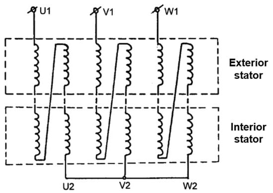
Figure 2.
The connection scheme of the stator windings in the asynchronous version.
2.3. Tubular Rotor with Squirrel Cage Winding
(a) Rotor squirrel cage. Regarding the construction of the rotor, there are several possibilities:
- The first is made of solid steel, with a copper cage either on the inner or outer surface. Such a machine could work with only the outer stator fed from the mains, or only with the inner one, or with both stators working in parallel. Assuming the copper cage is placed towards the inside of the rotor, in the first case, we are dealing with an asynchronous machine with a massive rotor; in the second case, there would be a classic machine in the cage; and in the last case, there would be two machines working in parallel. For this last situation, the characteristics will be a combination of the characteristics of the machine with a massive rotor and the machine with a cage coupled to the same shaft and fed through the stator windings, in parallel. For a given slip, the electromagnetic torque will be equal to the sum of the torques of each machine at that slip.
- The second is a normal cage placed in a magnetic circuit made of laminated sheets. The cage can be made of copper or die-cast aluminum. The notches stamped in the rotor plates will be closed to ensure the mechanical robustness of the assembly, although this solution leads to an increase in leakage flux.
The cage can be split into two cages separated by a central isthmus of 1.5–2 mm, as shown in Figure 3b.
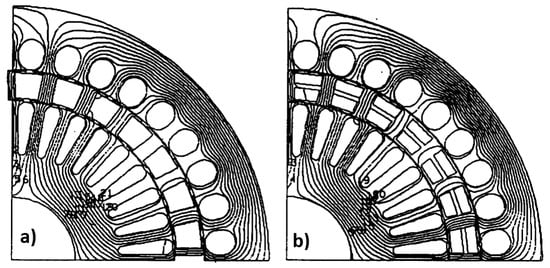
Figure 3.
The rotor cage. (a) The solution with a row of bars with semi-open rotor notches; (b) The solution with two cages separated by an isthmus, with closed notches.
(b) The shape of the rotor cage bars. After analyzing several shapes for the rotor cage bars (round; oval; rectangular; trapezoidal), two considerations emerged as important in choosing the shape: the rotor teeth should have a constant section (parallel walls), and the torque developed by the motor at high speeds (small slips) should have important values.
As in this situation, the electromagnetic torque is directly proportional to the rotor resistance relative to the stator :
It follows that for a rotor of a given radial thickness and a constant cross-section of the teeth, the trapezoidal cross-section bars provide the largest conductor cross-section.
Of course, with large slips (at start-up), the situation changes, but as for the proposed construction, we cannot count on the effect of pushing back the current. Thus, it remains that by choosing the material of the bar, the problem is solved in the form of a compromise. Indeed, when starting, a large section of the bars is not suitable because it reduces the starting torque, but it is beneficial for the performance of the machine.
It remains to be added that relations (3) and (4) were obtained through particularizations, from the general expression of the electromagnetic torque:
So, in conclusion, one will opt for bars of the trapezoidal section, made through brass-welded construction or made of aluminum, for pressure casting of the cage.
(c) The radial thickness of the rotor. If it is admitted that the section of the rotor teeth must be at least equal to that of the internal stator teeth and made by fixing the section of the rotor bars, the radial thickness of the rotor is unambiguous.
Special attention must be paid to the mechanical robustness of the cage and its fixing in the bracket on the flange. From this point of view, keeping the rotor slots open would lead to the fragmentation of the laminate plates—a mechanically inadmissible solution. The mechanical strengthening of the rotor requires the closing of the slots and the separation of the rotor bar into two trapezoidal bars separated by a central isthmus of 1.5–2 mm, which ensures the continuity of the middle of the laminate plates (Figure 3b). Before analyzing the electromagnetic influence of these measures, we note that the consideration of the above led to the establishment of the radial thickness of the rotor at the value of 18 mm.
We obtained the transversal geometry from Figure 4a, enabling us to also determine the flux distribution. The increase in leakage due to the closing of the slots has the effect of increasing the total leakage reactance, whose variation as a function of speed is represented in Figure 4b. Consequently, there was a reduction of the torque by approximately 3% in nominal mode and 6.5% at start-up. For the other characteristics of the machine, the influence of closing the notches is negligible.
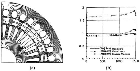
Figure 4.
The variant with closed notches. (a) Distribution of equipotential in geometry with closed notches and rotor isthmus; (b) Effect of notch closure on machine reactance.
(d) The influence of the number of bars. The study was carried out for Z2 = 20 and Z2′ = 28 bars, which agree for Z1 = 36 and 2p = 4.
The overall section of the rotor bars and teeth have been kept unchanged—a condition due to which the thickness of the rotor remains unchanged. The results of the field calculations show that the distribution of the same iron surface in a different number of teeth influences the flux distribution not only in the rotor teeth but also in the teeth of the two stators. The more important the number of rotor teeth (remaining within acceptable constructive limits), the more the distribution of the magnetic induction in the teeth of the three armatures approaches a sinusoid, and the abnormal saturation of some teeth is avoided.
The more favorable distribution of the flux in the teeth is felt in the increase of the power factor from 0.78 for Z2 = 20 to 0.83 for Z2′ = 28 (Figure 5), in the case of the studied geometry and—by the slight increase of the flux itself—in the increase of the electromagnetic torque by about 5%. For these reasons, the version with 28 rotor bars is preferred.
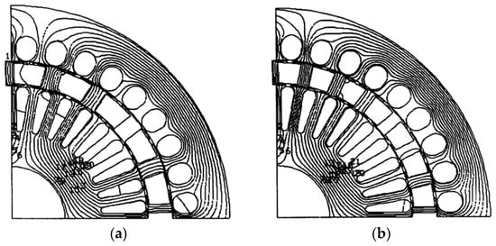
Figure 5.
Constructive variants with different numbers of bars: (a) Variant with 20 bars; (b) Variant with 28 bars.
2.4. Presentation Memorandum for the Technical Execution Project of the Three-Phase Asynchronous Motor with Double Stator
This section presents the execution project for the experimental model of a three-phase asynchronous motor with a double stator and a tubular cylindrical rotor, placed between the two stators. This project aims to create a product that performs as well as possible with high reliability and is relatively easy to execute, at least in the experimental project phase in specialized industrial laboratories.
Among the objectives pursued, we can mention the following: reduced inertia; a thin rotor in the radial direction; small axial dimensions; and the adequate exploitation of the double active transverse surface resulting from the creation of the second stator. Before dealing with the calculations of the experimental model, clarifications are needed related to the construction of the rotor—the most delicate part of the motor with a double stator and imposed tubular rotor. The shape of the rotor cage considerably depends on its production technology, namely by casting or assembling the cage bars with the two short-circuit rings, using the process of welding or gluing with a suitable alloy. In the first case, the cage will be made of aluminum, and in the second case, it will be made of copper or aluminum.
In the following, some details related to the sequence of operations for making the rotor are presented. Regarding the magnetic circuit laminated plates, the following sequence is prescribed: Stamping the central hole of the plate (diameter 80 mm); stamping the outer stator plate (diameter 320 mm); stamping the notches of the outer stator plate; cutting the outer stator plate from the rest of the material from which the rotor plate and the inner stator plate are to be made (cutting on the 225 mm diameter); step-by-step stamping of the rotor notches (simultaneously for the two levels of notches), to achieve a correct relative arrangement of the two layers of notches; cutting the inside of the rotor plate (cutting on the diameter of 180 mm); and stamping the notches of the inner stator plates.
Regarding the two stators of this type of motor, some observations must be made. First, it is required that the two stators have a certain relative position between them. If, for the package, inside the positioning is easy to achieve, by providing wedge nuts in the fixed shaft (one for fixing the toles on the shaft and another for fixing the shaft in the support shield of the inner stator) for the positioning of the outer stator, care must be taken when pressing it in the case (more precisely, in the holes in the case, intended for fixing the shields). The execution of the stator windings must be ensure they have well-defined positions concerning the two stators because the two stators did not place the winding exits on the same side of the tole packages; the exits from the inner stator winding are found on the side of the rotating shaft end of the motor, and the outputs from the external winding are on the other side of the respective package.
One of the objectives pursued when drawing up the technological project was to create an experimental model for the double-stator motor using as many existing devices as possible in the manufacture of electric machines already in production. In this sense, for the experimental model of the double-stator motor, the gauge figure of 200 (taken from normal asynchronous motors) was adopted. Their laminated plate is characterized by the machine manufacturer by an outer diameter of 320 mm. With the toles having this diameter, asynchronous motors with two, four, six, or eight poles are made. In the case of bipolar motors, the inner diameter of the stator is 180 mm, while for quadrupole motors, this diameter is 200 mm, and for those with six or eight poles, the value of the inner diameter is 225 mm. The double-stator asynchronous motor must have as large a diameter as possible at the inner hole of the outer stator to accommodate the rotor and the second stator. For this reason, the value of 180 mm cannot be retained for the inner diameter of the outer stator. The 200 mm inner diameter stator has 48 notches and the 225 mm diameter one has 54 notches.
Considering the unmodified use of the usual toles, some notches will result for the outer stator. For the six-pole motor, a number q = 3 notches per pole and phase corresponds. For this, the rotor of the asynchronous motor with 44 notches is employed. These Z2 = 44 notches will be adopted for making the experimental model, even though the notches of the prototype rotor will not resemble those of the tole of the usual rotor. For the second stator (inner stator), two variants will be analyzed: one with notches () and the second with a smaller number of notches, namely . As for the length of the coil pack, in practice, motors manufactured with stator coils with an inner diameter of 225 mm have the following coil lengths: 125–140–160–180–200–225–280–320 mm.
For the inner diameter of 225 mm and notches, the following widths result for the teeth of the outer stator:
At the bottom of the notch,
At the top of the notch,
In the calculations, we will work with the value of the width of the teeth equal to .
For the outer stator, the tooth pitch is
Thus is the calculation of the magnetic induction from the external stator teeth:
in which it was noted there was magnetic induction in the air gap.
The height of the stator yoke is determined as follows:
The polar step length τ′ at the inner surface of the outer stator is
For the magnetic induction in the external stator yoke, the following relation is used:
The rotor cage (for Z2 = 44) adopted has round copper bars so that there are no difficulties in supplying the material for these bars. The variants with diameters of 7 mm and 9 mm are analyzed; these types of bars are usually used for the manufacture of motors intended to drive submersible pumps. Starting from the currents that can appear in the rotor, it is found that it is necessary to insert either two bars with a diameter of 7 mm or two bars with a diameter of 9 mm in each notch, to obtain a reasonable value for the current density in the bars of the rotor cage.
The mechanical rigidity of the rotor, which, as we have seen previously, must be high, is given only by the bars of the rotor cage; they are the only elements with which the tole package is tightened to be rigid. In the specialized literature, there are also other methods of achieving the mechanical stiffening of the rotor. For the proposed solution, it should be specified that two bars in each notch can only be inserted under conditions where there are certain clearances (interstices) in the notch, but these clearances reduce the rigidity of the rotor, especially since it has a tubular shape. For this reason, the solution is adopted that each bar has its slot; so, from a physical point of view, there will be a double number of slots (the number of physical slots in the rotor will have to be 2 × 44 = 88). If 7 mm diameter bars are used, then 7.3 mm diameter slots are needed, and if 9 mm diameter ones are used, the rotor notches will be 9.3 mm in diameter (Figure 6).

Figure 6.
Arrangement of rotor notches: (a) The case of the 7 mm bar; (b) The case of the 9 mm bar.
As previously stated, the tubular rotor must have as little thickness for radial dimension as possible. If the two bars and their respective notches, which must be used instead of only one, were placed one below the other on the same radius, then the thicknesses of the isthmuses for each pair of slots would be quite small and the robustness of the rotor would be seriously affected. For this reason, a staggered arrangement of the bars in the upper notches compared to those in the lower notches of the rotor was resorted to. Solving this geometry problem, the dimensions of the isthmuses between the notches for the two cases of bars (7 mm and 9 mm) were established in the following figures.
The values above show that the use of bars with a diameter of 7 mm leads to isthmus values that give the rotor a much more robust construction. For the inner stator, the same number of notches () as for the outer stator is not used. The number of notches is adopted for the inner stator. The dimensions of the inner stator notches must be as large as possible, but they have a strong limitations due to magnetic saturation. Below we present the results obtained for two types of notches: a small one, marked with the symbol A, and a large, one marked with the symbol B. Figure 7 shows the notations used.
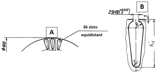
Figure 7.
Examples of two types of notches: small (A) and large (B).
As already specified, the surface of the notches of the inner stator is of great importance compared to the surface of the notches in the outer stator. However, the ratio between the magnetic induction in the teeth of the inner stator and the magnetic induction in the air gap between the rotor and the outer stator is also important; the calculation of the magnetic circuit is carried out using this induction as a starting point. The characteristics of notches A and B are presented in Table 1.

Table 1.
The characteristics of the two types of notches.
The type A notch, although it has a useful notch area equal to 36% of that of the outer stator notches, instead has lower inductances in the teeth compared to the inductances in the teeth between the type B notches. The latter has a useful notch area equal to 47.3% compared to those existing in the outer stator. As for the value of the air gaps between the rotor and the two stators, a value of 0.25 mm is adopted, and this value will be increased if difficulties arise in the manufacture of the experimental model. The Carter’s coefficient required to calculate the magnetic tension in the air gap has the following values: For the air gap between the rotor tooth and the outer stator, it is , while for the air gap between the rotor tooth and the internal stator, it is .
Considering the above, the calculation of the magnetic circuit can be performed. The results of this calculation are presented below, in Table 2, for the inner stator with type A notches with the magnetic inductions expressed in [T] and the magnetic voltages in [A].

Table 2.
Magnetic circuit calculation results.
To conduct a comparison between the magnetic circuits of the double-stator motor and the single-stator motor from which the first derives, in Table 3, the values of the magnetic voltage for these motors are specified for the inductions in the air gap with the values 0.1 T, 0.5 T, 0.6 T, 0.7 T, and 0.8 T.

Table 3.
Total magnetic tensions for various asynchronous motor configurations.
From Table 3, which contains the magnetic tension values for the entire magnetic circuit of the motors under comparison, the following aspects can be noted:
- Firstly, double-stator motors have a much more saturated magnetic circuit than similar motors made in the classical construction, which represents a disadvantage that, however, can be acceptable for intermittent operation in adjustable drives.
- Secondly, the area of the slots where the stator winding is to be placed is larger in the double-stator motor, which is an advantage.
- Thirdly, the magnetic circuit of the double-stator motor is less saturated in the case of type A notches compared to that of type B notches; for this reason, the type A notch is recommended, although it has a smaller useful surface.
(e) Equivalent air gap width. The determination of the air gap width of the equivalent machine can be performed by applying Ampère’s theorem for a contour that crosses the two real air gaps in the axes of two consecutive poles and which is closed by the stator yokes, considering only the fundamentals of the field in the air gap and the spatial distribution of the currents:
with being the resultant magnetomotive tension of the three windings.
The presence of notches is considered using Carter’s coefficient:
and, respectively,
where , , , and are Carter’s coefficients for the notched bores on both sides of the air gaps, and and are the lengths of the actual air gaps.
Writing relation (13) in the form
the value of the equivalent gap and the value of the field from this gap are deduced:
(f) Equivalent air gap diameter. The calculation of an equivalent diameter for the two gaps can be carried out starting from the condition of the equality of the useful fluxes (neglecting the escapes through the rotor isthmuses). In this situation, for the double-stator machine, the fundamental useful flux chaining the three armatures can be written for each of the two air gaps:
where is the active length of the machine and , are the polar steps at the level of the internal and external air gaps.
For the equivalent machine, the useful flux is obtained taking into account the expression (17) of the magnetic field in the gap:
From (18) and (19), we obtain
and taking into account that , we obtain
It is easy to prove that the equivalent diameter is between the two real diameters of the air gaps:
2.5. Simulation Results for the Two-Stator and One-Tubular-Rotor Induction Motor
Figure 8 presents the transverse geometry and the discretization network (approximately 46,000 nodes) for the two-stator and one-tubular-rotor induction motor.
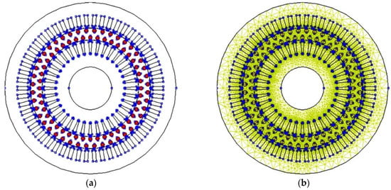
Figure 8.
(a) Transverse geometry; (b) The discretization network.
Figure 9 presents the simulation results for magnetic flux at idle operation and for magnetic induction at idle operation for the two-stator tubular, one-rotor induction motor only with the outer stator powered.
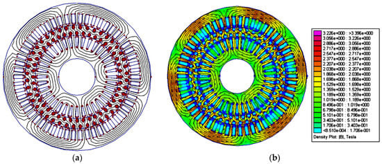
Figure 9.
(a) Magnetic flux at idle operation; (b) Magnetic induction at idle operation.
Figure 10 presents the simulation results for the magnetic induction in the outer and inner space for the two-stator tubular, one-rotor induction motor only with the outer stator powered at idle operation.
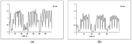
Figure 10.
(a) Magnetic induction in the outer space; (b) Magnetic induction in the inner space.
Figure 11 presents the simulation results for the magnetic flux at idle operation and magnetic induction at idle operation for the two-stator tubular, one-rotor induction motor only with the inner stator powered.
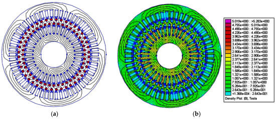
Figure 11.
(a) Magnetic flux at idle operation; (b) Magnetic induction at idle operation.
Figure 12 presents the simulation results for the magnetic induction in the outer and inner space for the three-phase asynchronous motor with two stators and one-rotor radial air gap only with the inner stator powered.
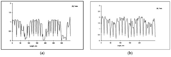
Figure 12.
(a) Magnetic induction in the outer space; (b) Magnetic induction in the inner space.
Figure 13 presents the simulation results for the magnetic flux at idle operation and magnetic induction at idle operation for the two-stator tubular, one-rotor induction motor with both stators fed in series.
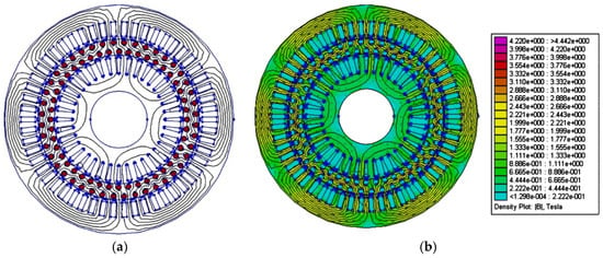
Figure 13.
(a) Magnetic flux at idle operation; (b) Magnetic induction at idle operation.
Figure 14 presents the simulation results for the magnetic induction in the outer and inner space for the three-phase asynchronous motor with two stators and one-rotor radial air gap with both stators fed in series.
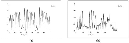
Figure 14.
(a) Magnetic induction in the outer space; (b) Magnetic induction in the inner space.
Thus, below, we present some of the simulation results for the two-stator tubular-rotor induction motor using QuickField™ 6.0 software, which is a very efficient finite element analysis package for electromagnetic, thermal, and stress design simulation with a multi-analysis coupled field. The analysis was performed for the cases where only the outer stator is powered, when only the inner stator is powered, and when both stators are powered in series, at no-load operation.
3. Results
3.1. Conception and Execution of the Prototype
In the first phase, entitled “Research and modeling”, the theoretical bases of the topic proposal were finalized, and the constructive proposals were established based on electromagnetic field calculations and simulations using the finite element method. Initially, induction motors were considered, as we sought to use a part of the rotor yoke to make the second inductor. During the study, it became obvious that the rotor must be pushed as far as possible to the outside of the machine, presenting the idea of creating a synchronous version where the rotor—interchangeable with the one in the cage—is equipped on both bores with permanent magnets of high magnetic energy. Preliminary calculations and modeling seem to have confirmed the fact that the synchronous version is more efficient than the asynchronous one. The simplicity of the construction of the asynchronous variant and the possibility of the interchangeability of the rotor required the realization of the prototype of the asynchronous variant first and the provision of a new phase for the prototype of the synchronous variant.
In the second phase, the “Technical Project” was drawn up for the prototype of the asynchronous motor with two stators; in fact, this was an execution project at the prototype level, using the usual benchmarks and technology. Factory-level execution drawings were prepared for all parts and subassemblies.
Execution of the prototype. The construction of the prototype in the asynchronous version was carried out based on the execution drawings produced in phase I of the general assembly. Mainly, the following functional subassemblies were made:
- The first was the external stator with winding, which included the tole package, with existing landmarks and the respective inductor winding. The electromagnetic circuit was fixed in a casing with welded longitudinal ribs. In general, the execution of this subassembly did not pose any particular problems, except for the machining of the casing and obtaining perfect concentricity between the interior of the tole package and the sills of the casing.
- The second was the internal stator with winding, whose magnetic circuit was made by a combination of existing constructive elements (molds for notches and internal and external cutting of metal sheets). The tole package was fixed to an axially drilled hub to remove the cables from the inner inductor winding, which also provides a support surface for the 6312 P63-2Z bearing from Eurobearings Brasov (Brașov, Romania) and machined shield. The high-precision processing of the surfaces and thresholds involved ensuring the concentricity of the two stators, and the tubular rotor constituted the most important stage of the prototype’s execution, given the reduced width of the air gap (0.25 mm).
- The third was the rotor in short circuit (in the cage), which required the execution of molds for notches and the adaptation of molds for the internal and external cutouts. The short-circuit winding contains a double cage of round copper bars welded at both ends into short-circuit rings. For this subassembly, the processing of the rotor cage and the support flanges required the same accuracy, with the deviations from concentricity and tolerances being in the order of microns.
For the assembly of the prototype motor, other parts (shaft, shields, bearing caps, wedges) or typical landmarks (bearings, safety rings, screws, grower washers) were needed. The motor construction type selected was IMB 3 (with flange) for easier mounting and centering on existing test fixtures.
3.2. Conducting Experimental Tests at the Test Stand
The tests of the proposed prototype were carried out in the test stand of the central laboratory of SC UMEB SA, thus ensuring the possibility of rapid interventions or adjustments within the test program (for example, the connection of the two stators, or the relative rotation of one concerning the other). Also, performing the tests in a neutral laboratory guaranteed complete impartiality in the assessment of the results.
The specialists from UMEB, who acted beneficially throughout the work as competent and neutral moderators, believe that a clear conclusion can be drawn only by comparing it with a classic motor made in a magnetic circuit with the same volume and the same configuration (the same outer diameter and same package length).
There is a belief that the prototype of the asynchronous variant can be optimized by exploiting the heating reserve and balancing the solenation in the two stator inductors. Experimental results are specified in the test reports. Below (Table 4), we present the results obtained during the test of the asynchronous motor prototype with a double stator and a tubular rotor, in the form of a professional test report, following the requirements and practices of the homologation documents.

Table 4.
The values of the main constructive characteristics of the three-phase asynchronous motor with a double stator and single rotor with the radial air gap.
3.3. Test Report 1
In Figure 15, we present the connection diagram used for Test Report 1 (only the outer stator is powered). The connection diagrams correspond to the tests of the prototype and represent how the two outer and inner stators are interconnected and powered. This is also explicated in Figure 3.
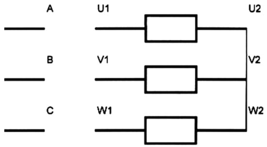
Figure 15.
Connection diagram for Test Report 1.
The diagrams from Figure 16, Figure 17, Figure 18, Figure 19, Figure 20 and Figure 21 correspond to the two-stator asynchronous motor for no-load and short-circuit operation with only the outer stator powered. The diagrams presented are as follows: Line voltage at idle—No load current; Power absorbed at idle—Line voltage at idle; Power factor at idle—Line voltage at idle; Short-circuit phase current—Line voltage at short-circuit operation; Power absorbed at short circuit—Line voltage at short-circuit operation; and Short-circuit current calculated—Line voltage at short-circuit operation.
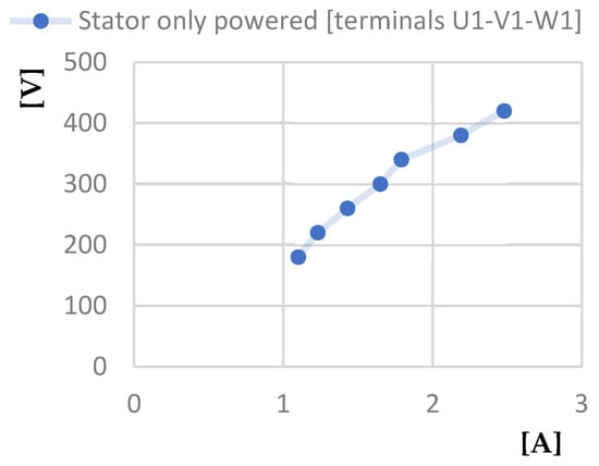
Figure 16.
Line voltage at idle [V]—No load current [A] characteristic.
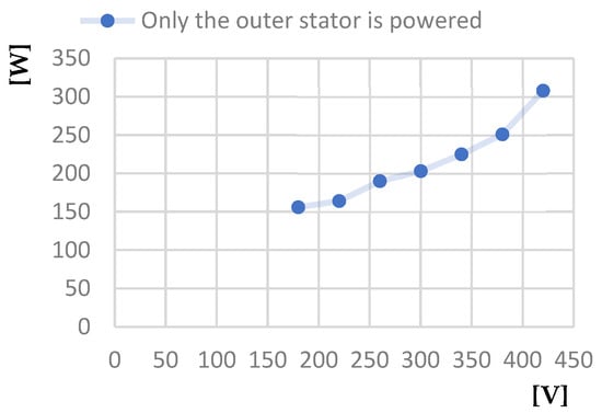
Figure 17.
Power absorbed at idle [W]—Line voltage at idle [V] characteristic.
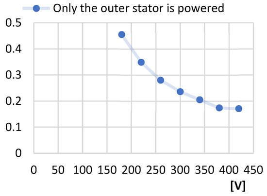
Figure 18.
Power factor at idle—Line voltage at idle [V] characteristic.
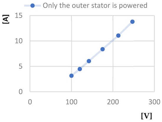
Figure 19.
Short-circuit phase current [A]—Line voltage at short-circuit operation [V] characteristic.
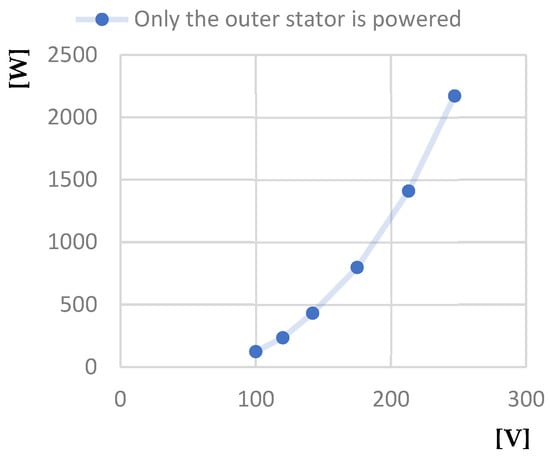
Figure 20.
Power absorbed at short circuit [W]—Line voltage at short-circuit [V] characteristic.
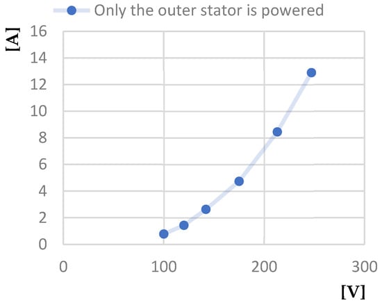
Figure 21.
Short circuit current calculated [A]—Line voltage at short-circuit [V] characteristic.
3.4. Test Report 2
In Figure 22, we present the connection diagram used for Test Report 2. For this test, only the inner stator of two stators and the one-rotor asynchronous motor is powered.
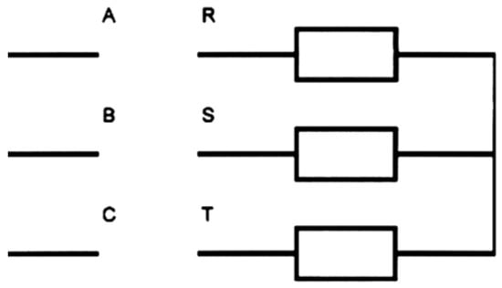
Figure 22.
Connection diagram for Test Report 2.
The diagrams presented in Figure 23, Figure 24, Figure 25, Figure 26, Figure 27 and Figure 28 correspond to the two-stator asynchronous motor for no-load and short-circuit operation with only the inner stator powered. The diagrams presented are as follows: Power factor at idle—Line voltage at idle; Power absorbed at idle—Line voltage at idle characteristic; Line voltage at idle—No-load current; Short circuit current calculated—Line voltage at short-circuit; Power absorbed at short-circuit—Line voltage at short-circuit; and Short-circuit phase current—Line voltage at short-circuit.
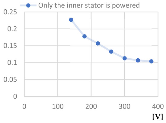
Figure 23.
Power factor at idle—Line voltage at idle [V] characteristic.
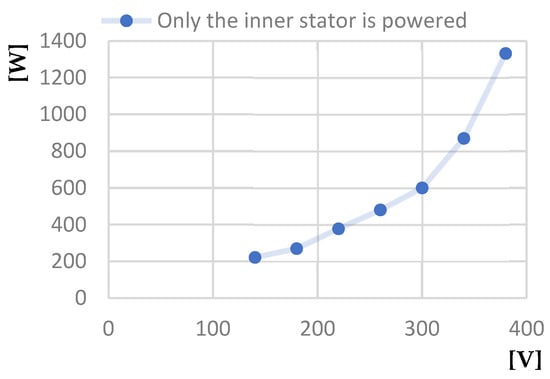
Figure 24.
Power absorbed at idle [W]—Line voltage at idle [V] characteristic.
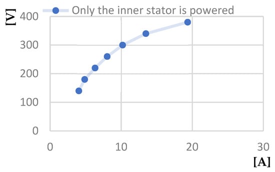
Figure 25.
Line voltage at idle [V]—No-load current [A] characteristic.
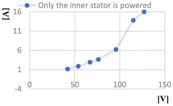
Figure 26.
Short circuit current calculated [A]—Line voltage at short-circuit operation [V] characteristic.
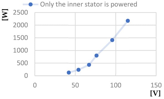
Figure 27.
Power absorbed at short-circuit [W]—Line voltage at short-circuit [V] characteristic.
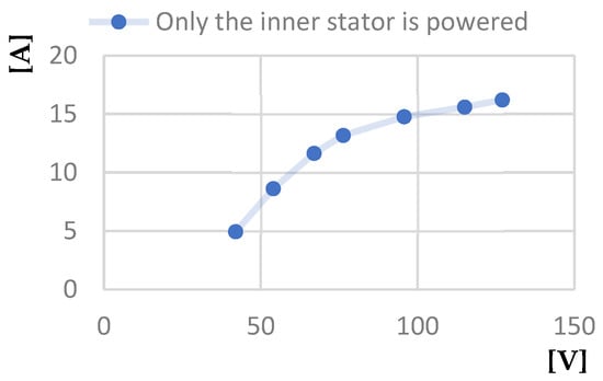
Figure 28.
Short-circuit phase current [A]—Line voltage at short-circuit [V] characteristic.
3.5. Test Report 3
Figure 29 and Figure 30 present the connection diagram corresponding to the two-stator motor with the series feeding from the windings of both stators and developing torques in the same direction, as well as the connection diagram corresponding to the two-stator motor with the series feeding from the windings of both stators and developing torques in the opposite direction to Test Report 3.

Figure 29.
The connection diagram develops torques in the same direction.

Figure 30.
The connection diagram develops torques in the opposite direction.
The diagrams in Figure 31, Figure 32, Figure 33, Figure 34, Figure 35 and Figure 36 correspond to the two-stator asynchronous motor for no-load and short-circuit operation with the series feeding from the windings of both stators.
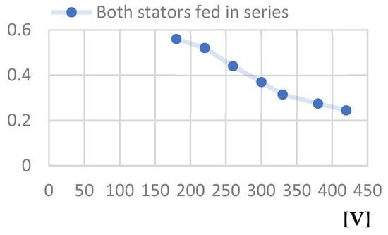
Figure 31.
Power factor at idle—Line voltage at idle [V] characteristic.
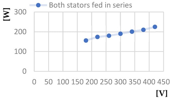
Figure 32.
Power absorbed at idle [W]—Line voltage at idle [V] characteristic.
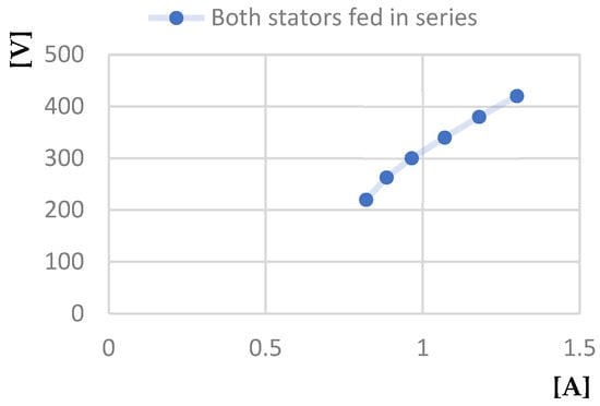
Figure 33.
Line voltage at idle [V]—No-load current [A] characteristic.
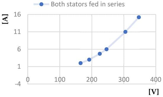
Figure 34.
Short circuit current calculated [A]—Line voltage at short-circuit operation [V] characteristic.
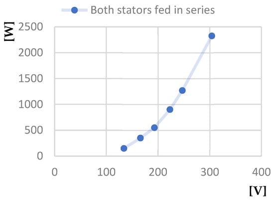
Figure 35.
Power absorbed at short-circuit [W]—Line voltage at short-circuit [V] characteristic.
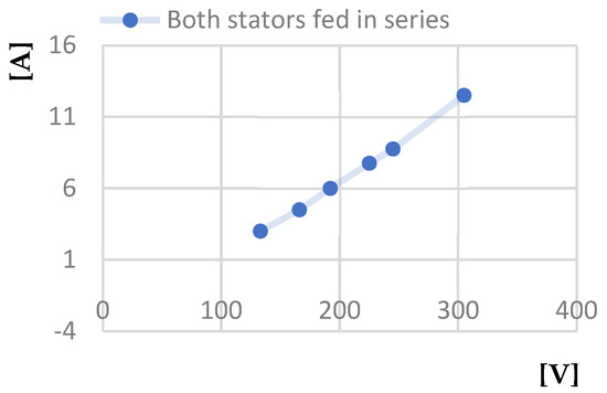
Figure 36.
Short circuit current calculated [A]—Line voltage at short-circuit [V] characteristic.
The diagrams presented are as follows: Power factor at idle—Line voltage at idle; Power absorbed at idle—Line voltage at idle characteristic; Line voltage at idle—No-load current; Short circuit current calculated—Line voltage at short-circuit; Power absorbed at short-circuit—Line voltage at short-circuit; and Short-circuit phase current—Line voltage at short-circuit.
Compared to operating with only the outer stator or only the inner stator, we can draw some conclusions for the case of operating with both stators powered in series:
- The first is that the power factor value is higher when both stators are powered, being approximately 0.55 at a line voltage of 200 V, compared to the value of 0.4 for the same line voltage when operating with only the outer stator powered, and only 0.17 when operating with only the inner stator powered.
- The second is that the power absorbed by the motor when operating in no-load mode at a voltage of 250 V, when both stators are powered, is 170 W, compared to the value of 210 W for operating with only the outer stator powered and of over 300 W for operating with only the inner stator powered.
- The third regards the power absorbed by the motor when operating in short circuit at a voltage of 250 V—in the case of powering both stators, it is 1200 W, compared to the value of 2000 W for the case of operation with only the outer stator powered and of over 3500 W for the case of operation with only the inner stator powered.
Consequently, it can be observed that when both stators of the analyzed motor are powered in series, it has superior characteristics compared to machines with a single stator in the classic construction.
3.6. Test Report 4
In Figure 37, we present the connection diagram used for Test Report 4. In this connection diagram, the windings of both stators feed in series, and the two-stator and one-tubular-rotor asynchronous motors function in the load operation.
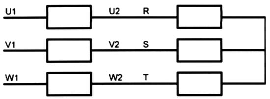
Figure 37.
The connection diagram in load operation.
The diagrams presented in Figure 38, Figure 39, Figure 40 and Figure 41 correspond to the two-stator motor with the series feeding from the windings of both stators for the load operation.
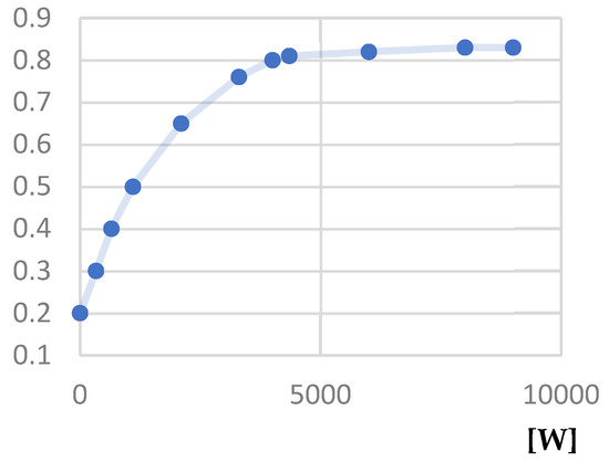
Figure 38.
Power factor—Useful power [W] characteristic.
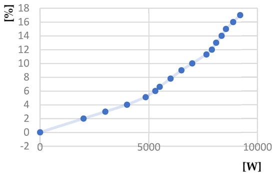
Figure 39.
Slip [%]—Useful power [W] characteristic.
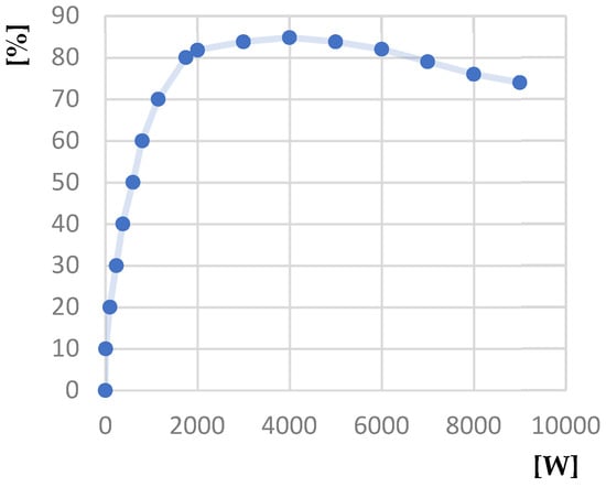
Figure 40.
Yield [%]—Useful power [W] characteristic.
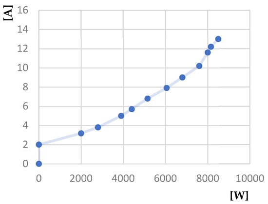
Figure 41.
Absorbed current [A]—Useful power [W] characteristic.
The diagrams presented are as follows: Power factor—Useful power; Slip—Useful power; Yield—Useful power; and Absorbed current—Useful power.
4. Conclusions and Discussions
Concerning the problem addressed and the objectives pursued, this research had, in essence, an applicative and experimental character. The theoretical interventions referred to the establishment of the equivalent scheme of alternating current machines with two iron gaps, with or without taking into account iron losses; to the determination of the parameters corresponding to this scheme; and to the methods of quantifying the influence of saturation on the parameters of the machine.
An important weight in the research activity carried out was the solutions of some magnetic field problems provided by the finite element method, using professional calculation programs, in various configurations of the transverse geometry of the tubular rotor, with respect to its short-circuit winding. At this stage, it emerged that the electromagnetic torques developed by the machine (in fact, by the two elementary machines consisting of the two stator armatures and the common rotor) would lead to the achievement of superior performances compared to the equivalent standard machine, with the same volume of iron. Instead, calculating the electromechanical constants defined a rotor with very little inertia—a quality that can be imposed in some flexible drives. The prototype of this type of machine was surprising due to the ease with which the rotor can be turned, concerning other machines of similar size.
The development of the project of the machine with two air gaps in the asynchronous version gave rise to extensive research activity, both from a purely electrical point of view and the actual mechanical construction. From the electrical point of view, the following problems were analyzed: the distribution of the number of turns on the two stator windings; the possibility of shifting one to another by a certain angle of the two stators, external and internal; the axial inclination of the notches; and the isthmus game in the rotor cage. From the point of view of the actual mechanical construction, a special problem consisted of obtaining small radial air gaps, which are characteristic of asynchronous machines. In the case of the prototype made, these radial air gaps were 0.25 mm. The optimal variant proposed contained a different number of notches for the two stators (54 for the outer stator and 36 notches for the inner stator, for six poles) and, correspondingly, the number of turns per phase was higher for the outer stator.
Regarding the rotor, the double-cage solution with bars of the trapezoidal section proved to be the most advantageous, allowing for a certain control of the direction of the field lines. The very small quantities required for the execution of the experimental prototype could not be honored by the traditional suppliers of drawn copper bars, so a double cage of round bars was executed.
An aspect that was very poignant was achieving the centering of the rotor between the two stators and the transmission of the rotational torque to the motor shaft. Compared to the existing solutions, a novel construction was developed, with the sectioning of the machine shaft. One part—axially drilled to allow the cables to be removed from the internal stator winding—remained fixed and integral with the motor shield, and the other—which also contains the free end of the shaft—was driven by the rotor in its movement. There was also the idea of making the tubular rotor in the console, but it was abandoned because, in the case of technological processing inconsistencies, the concentricity of the bores along the entire length of the fittings could have been compromised. The objective of making a reliable motor led to the proposal not resorting to the flanged construction of the rotor—a solution that, although theoretically feasible, may present difficulties in practical implementation and operation, including an inevitable residual mechanical imbalance. Making the unilateral magnetic attraction more intense in some regimes—for example, at start-up or overload—can lead to friction between the rotor and one of the stators.
The recent development of permanent-magnet synchronous motor constructions has led to the concept of making such motors in the previously specified constructive configuration, with two stators and two radial gaps. In the future, there may be problems such as keeping the two stators unchanged (including the windings, to allow for performance comparison) and building an interchangeable tubular rotor equipped with permanent magnets of high specific energy.
Author Contributions
Conceptualization, M.-F.S. and I.B.; methodology, M.-F.S., I.B. and E.-O.V.; software M.-F.S., I.B. and E.-O.V.; validation, M.-F.S., I.B., C.C., A.-G.H. and E.-O.V.; formal analysis, A.-G.H. and C.C.; investigation, M.-F.S., I.B., C.C., A.-G.H. and E.-O.V.; resources, M.-F.S.; writing—original draft preparation, M.-F.S. and A.-G.H.; writing—review and editing, M.-F.S., I.B., C.C., A.-G.H. and E.-O.V.; visualization, I.B. and A.-G.H.; supervision, M.-F.S. and E.-O.V. All authors have read and agreed to the published version of the manuscript.
Funding
This research was funded by Valahia University of Targoviste.
Data Availability Statement
Data are contained within the article.
Conflicts of Interest
The authors declare no conflicts of interest.
References
- Komeza, K.; Dems, M.; Wiak, S.; Libera, R.; Pietrzak, J.; Stando, P.; Tomczyk, K. Influence of the Cast Iron Frame on the Distribution of the Magnetic Field in the Stator Yoke and Additional Power Losses in the Induction Motor. Electronics 2024, 13, 119. [Google Scholar] [CrossRef]
- Aarniovuori, L.; Niemelä, M.; Pyrhönen, J.; Cao, W.; Agamloh, E. Loss Components and Performance of Modern Induction Motors. In Proceedings of the 2018 XIII International Conference on Electrical Machines (ICEM), Alexandroupoli, Greece, 3–6 September 2018; pp. 1253–1259. [Google Scholar]
- Bucci, G.; Ciancetta, F.; Fiorucci, E.; Mari, S.; Segreto, M.A. The Measurement of Additional Losses in Induction Motors: Discussion about the Actually Achievable Uncertainty. Energies 2020, 13, 78. [Google Scholar] [CrossRef]
- Al-Rawashdeh, A. Losses Reduction of Induction Motors Operating Below the Nominal Load. Int. J. Electr. Comput. Sci. IJECS-IJENS 2017, 17, 1–5. [Google Scholar]
- Balci, S.; Akkaya, M. Reduction of the core size and power losses by using soft magnetic material for a single-phase induction motor. Measurement 2022, 198, 111421. [Google Scholar] [CrossRef]
- Vondršek, Z.; Ryenko, V.; Linda, M. Thermal analysis of asynchronous machines under intermittent loading. Agron. Res. 2019, 17, 1246–1254. [Google Scholar]
- Liu, Y.; Yue, B.; Kong, X.; Chen, H.; Lu, H. Design and performance analysis of a vane-shaped rotating receiver hole in high radius pre-swirl systems for gas turbine cooling. Aerosp. Sci. Technol. 2021, 115, 106807. [Google Scholar] [CrossRef]
- Nagpal, C.; Jain, P.; Reddy, V. Rotor vent hole shape studies on totally enclosed fan cooled motor. In Proceedings of the 2012 IEEE International Conference on Power Electronics, Drives and Energy Systems (PEDES), Bengaluru, India, 16–19 December 2012; pp. 1–6. [Google Scholar]
- Zhao, X.; Qin, P.; Tang, Z. Equivalent Inertia Estimation of Asynchronous Motor and Its Effect on Power System Frequency Response. Energies 2022, 15, 8350. [Google Scholar] [CrossRef]
- Kidd, B. Vector-Based Magnetic Circuit Modelling of Induction Motors. Magnetism 2022, 2, 130–151. [Google Scholar] [CrossRef]
- Burduniuc, M.; Nuca, I.; Cazac, V.; Ambros, T.; Mangos, O. Magnetic field analysis in asynchronous motors with six-phase windings. Ann. Fac. Eng. Hunedoara Int. J. Eng. 2022, 3, 55–60. [Google Scholar]
- Mykhailiuk, O. Magnetic field analysis of an induction machine with multiphase stator winding through finite element method. Int. J. Mech. Eng. Technol. 2018, 9, 789–801. [Google Scholar]
- Cao, Y. Optimal Design of Asynchronous Motor based on Finite Element Simulation. Trans. Comput. Sci. Intell. Syst. Res. 2023, 1, 182–192. [Google Scholar] [CrossRef]
- Soman, A.; Holmukhe, R.; Bharadwaj, D.G. Multispeed Operation and Testing of Dual Stator Winding Induction Machine. Int. J. Sci. Technol. Res. 2020, 9, 3025–3028. [Google Scholar]
- Huang, P.; Li, H.; Yang, C. A Yokeless Axial Flux Induction Motor for Electric Vehicles Based on Grain-oriented Silicon Steel. J. Phys. Conf. Ser. 2021, 1815, 012042. [Google Scholar] [CrossRef]
- Soman, A.; Madaan, S.; Gupta, S.; Singh, A.; Yadav, V.; Tiwari, A. Performance Analysis of Dual Stator Induction Motor. Int. J. Sci. Technol. Res. 2018, 5, 1969–1973. [Google Scholar]
- Idoko, E.; Obe, E.S.; Agber, J.U. Operation of Single-Phase Induction Motor with two Identical Stator Windings. Am. J. Eng. Res. 2016, 5, 13–19. [Google Scholar]
- Romodin, A.V.; Kuznetsov, M.I. A way to start an induction motor during a change in the voltage phase on one of two stator windings. Russ. Electr. Eng. 2015, 86, 339–343. [Google Scholar] [CrossRef]
- Fransua, A.; Măgureanu, R. Electrical Machines and Drive Systems; Technical Press: Oxford, UK, 1984. [Google Scholar]
- Tulicki, J.; Sobczyk, T.J.; Sułowicz, M. Stator current spectrum analysis of a double cage induction motor with rotor asymmetry. Arch. Electr. Eng. 2023, 72, 357–371. [Google Scholar]
- Kalra, S. Rotor Material Selection for High-Speed Double Cage Solid Rotor Induction Motor. J. Electr. Eng. Technol. 2023, 18, 2885–2894. [Google Scholar] [CrossRef]
- Yahaya, E.A.; Omokhafe, T.; Agbachi, E.; James, A. Advantage of Double Cage Rotor over Single Cage Rotor Induction Motor. Innov. Syst. Des. Eng. 2015, 6, 1–4. [Google Scholar]
- Sinha, S.; Deb, N.; Biswas, S. The Design and its Verification of the Double Rotor Double Cage Induction Motor. J. Inst. Eng. 2017, 98, 107–113. [Google Scholar] [CrossRef]
Disclaimer/Publisher’s Note: The statements, opinions and data contained in all publications are solely those of the individual author(s) and contributor(s) and not of MDPI and/or the editor(s). MDPI and/or the editor(s) disclaim responsibility for any injury to people or property resulting from any ideas, methods, instructions or products referred to in the content. |
© 2024 by the authors. Licensee MDPI, Basel, Switzerland. This article is an open access article distributed under the terms and conditions of the Creative Commons Attribution (CC BY) license (https://creativecommons.org/licenses/by/4.0/).