1. Introduction
Forest fires are disasters for animals and plant resources in the forest, which also cause devastating losses for the entire forest ecosystem. Extinguishing the initial fire is the key to forest fire prevention, which requires the monitoring and timely detection of forest fires. At present, the commonly used forest fire monitoring methods mainly include artificial ground patrol, watchtower lookout, a fire-watch system, aviation patrol, and satellite monitoring [
1,
2,
3,
4,
5]. An artificial ground patrol is inefficient, with the sight being easily blocked and large manpower being needed to be invested. The watchtower can be utilized for carrying out fire monitoring in the long term, but a network of watchtowers should be established, which includes a large number of full-time staff and heavy investment in materials as well as equipment [
2]. The fire-watch system put into use in Germany is an automatic forest fire warning system utilizing digital camera technology. However, the installation of the system with a monitoring radius of 10 km requires 75,000 EUR per set [
3]. Aviation patrol has the merits of enhanced efficiency, a wide range, and the timely detection of fire points, but the aircraft is expensive to use and maintain, which determines its utilization only in the key period of fire prevention. Satellite monitoring boasts the advantages of a wide range and low cost. Nevertheless, it is greatly affected by the weather [
4]. As a new type of aviation platform, the drone is highly mobile, safe, and reliable, and easy to operate while low in price. It can be loaded with various monitoring equipment and carry out aerial operations without being limited by the terrain of the forest area [
5]. With the maturity of the technology, it is expected to replace helicopters for aviation patrols and forest fire monitoring.
The multi-rotor drone is the most suitable for forest fire monitoring operations, due to its straightforward operational benefits, high reliability, strong maneuverability, vertical take-off and landing without a runway, etc. [
6]. Oil-powered drones have strong endurance, which is required in forest fire monitoring. However, the drone utilizes a gasoline engine as the power source, and accidents such as accidental crashes during operation above the forest area may cause fires [
7]. This type of risk can be reduced by using a battery as the power source of the UAV platform, but the flight time of the system is greatly reduced and the work efficiency is lowered [
8]. In addition, UAVs encounter a decrease in endurance with an increase in payload. For example, the existing lithium battery multi-rotor drones boast about 30 min of flight time without any payload, but when fitted with a camera (6 kg), the time is dramatically reduced to about 16 min of usable flight time.
Despite significant technological efforts to enhance UAV endurance through the development of new models and advancements in battery technology, achieving substantial breakthroughs in the short term remains a challenge. To meet the endurance requirements necessary for tasks such as forest fire monitoring in vast areas, the provision of a continuous power source is essential.
There are many charging methods for drones, such as traditional wired charging, wireless charging via electromagnetic induction, solar power by equipping photovoltaic panels, laser charging through remote energy transmission, fuel cells for chemical-to-electricity conversion, supercapacitors for rapid peak power delivery, and charging stations for convenient recharging [
9,
10,
11,
12]. Charging methods for drones operating in vast forests have primarily focused on three main approaches: transmission line-based charging, solar-based charging, and laser-based charging [
13,
14,
15,
16,
17]. The transmission line-based charging method involves an autonomously charged unmanned prototype that uses the magnetic field emitted by transmission lines to locate an optimal charging position for self-charging. However, this method has a limited scope of application and poses potential security risks to the transmission lines. Solar-powered drones offer an alternative for achieving extended endurance and long-range flight, but the availability of solar irradiance is not guaranteed during a flight, which can impede their performance [
9,
10].
Laser-based charging systems have demonstrated potential, with one system successfully extending the continuous flight time of the Stalker UAV to 48 h in a wind tunnel test [
11,
12]. Furthermore, a laser-powered UAV wireless communication system has been proposed, where the UAV harnesses energy from the laser power link to support its flight and transmit downlink RF information to a ground station [
12]. While the advantages of laser charging for drones are significant, challenges such as energy conversion efficiency, laser transmission efficiency, accurate tracking, and safety protection still need to be addressed [
14,
15,
16,
17].
A microgrid is a compact power distribution network that integrates distributed generation sources, energy storage units, conversion equipment, connected loads, and systems for monitoring and protection. It operates as a self-sufficient entity capable of self-governance, safeguarding, and management [
18,
19,
20]. Its most prominent advantage is that it can operate independently without connecting to the main power network, which determines its adaptability in remote forest areas [
21]. Therefore, it can effectively utilize locally abundant wind energy, photovoltaic energy, and other natural energy sources to generate clean energy for forest fire surveillance drones. The selective construction of microgrids at decentralized locations in forests can resolve the problem of charging infrastructure vacancy for drones in remote forest areas and assist the drones in penetrating large-scale forest areas for fire surveillance.
Based on the above motivations, a novel microgrid-based hierarchical charging framework for fire surveillance drones is presented in this paper. Firstly, according to the varying charging scenarios, the structure and different operation modes of the microgrid are proposed. Secondly, the hierarchical charging framework and corresponding replenishment method of UAVs based on a microgrid in a forest area is specified, which is designed to support continuous surveillance. In the following, an improved coordination control with a speed regulation strategy for the forest microgrid is presented, which constructs the key part of the model predictive method of power control in the microgrid. Finally, simulations are conducted under different charging scenarios to verify the feasibility of the proposed method.
2. General Design of Forest Microgrid
2.1. The Exclusive Load of the Microgrid
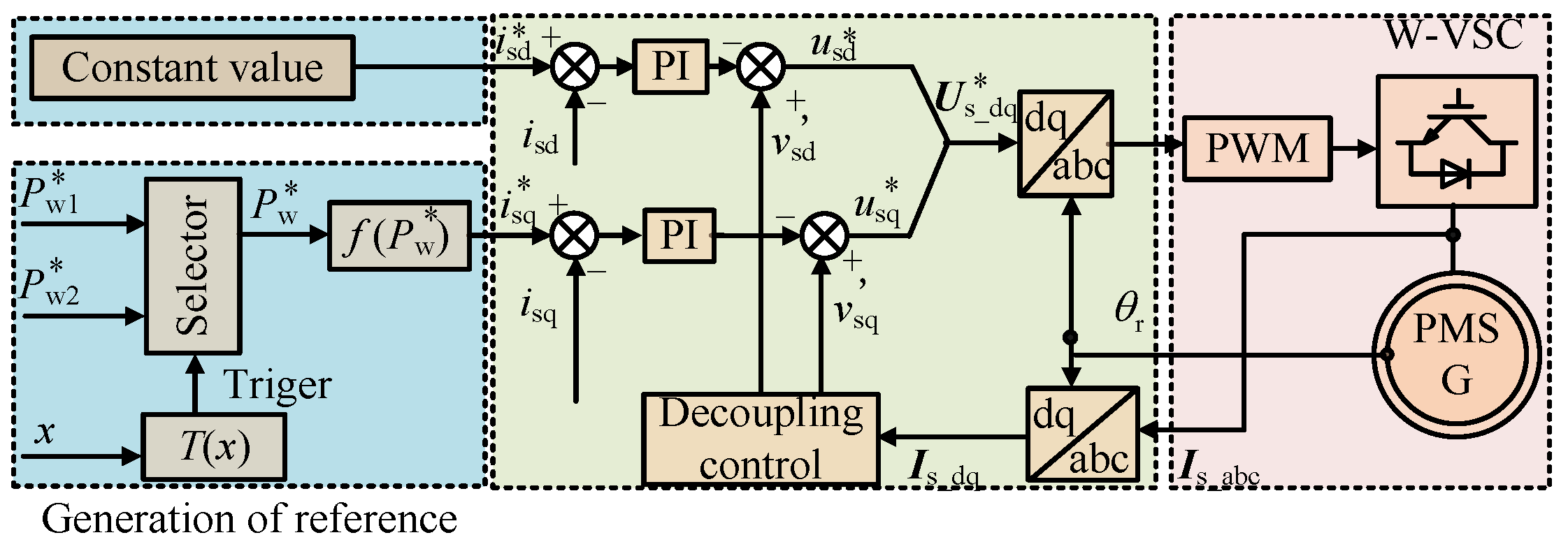
As different missions using the UAVs in the forest need to be accomplished, the models of the UAVs in the proposed framework are heterogeneous in terms of onboard processing, endurance, and sensorial capabilities. For example, some UAVs are equipped with infrared and visual video cameras, while others possess a still high-resolution camera and a specialized fire sensor. Therefore, three types of UAVs are organized to perform different tasks and are positioned at different layers as shown in
Figure 1. A mother drone may receive requests for charging from multiple child drones within its rechargeable areas. At the same time, the control center determines the charging priority and the rendezvous points for airborne docking at the low layer through optimization. When charging is completed, the mother drone returns to its own layer (middle layer), preparing for continuous support or seeking power support from the supremacy drone. Being different from the mother drones, the supremacy drone has the dual identities of mobile communication base station and charging station, and is connected to the ground microgrid through a power/signal composite cable with the rendezvous point for charging being within its scope of activities. The power source of each type of drone is shown in
Table 1.
2.2. Composition of Microgrid for Fire Surveillance Drones in Forest Area
The energy source of the whole surveillance system, including heterogeneous drones, is the microgrid established in an isolated forest. It is a low-cost utilization method of renewable energy with the benefits of low-cost investment, dependable energy provision, and adaptable management [
22,
23]. In the forest microgrid, the copious wind energy potential, biomass energy sources, and storage facilities are utilized locally to generate clean power continuously. Due to this feature, it can operate in a self-sufficient way in a desolate place far away from the utility grid and is thus referred to as an islanded microgrid. The forest microgrid utilizes a DC bus system, offering the benefits of flexible control, minimal line losses, and superior conversion efficiency. These advantages make it a more desirable connection scheme compared to its AC alternative [
24,
25]. A typical islanded forest microgrid is shown in
Figure 2, in which radiation topology is adopted. W-VSC, M-VSC, B-VSC, and L-VSC represent the converter of each unit in this figure.
A single microgrid is unable to meet the power demands of the huge aviation monitoring system in a vast forest area. Generally, networked microgrid systems should be designed according to the area to be monitored, the number of drones, and the requirements for monitoring accuracy, and they need to be set up in relatively flat areas on forest hills. However, the layout of the microgrid network is beyond the scope of this paper. In the following, the operation mode and predictive control methods, as well as the discrete control in the microgrid relating to charging the aerial vehicles, are presented.
2.3. Operation Mode of Microgrid for Fire Surveillance Drones
- (1)
Free mode
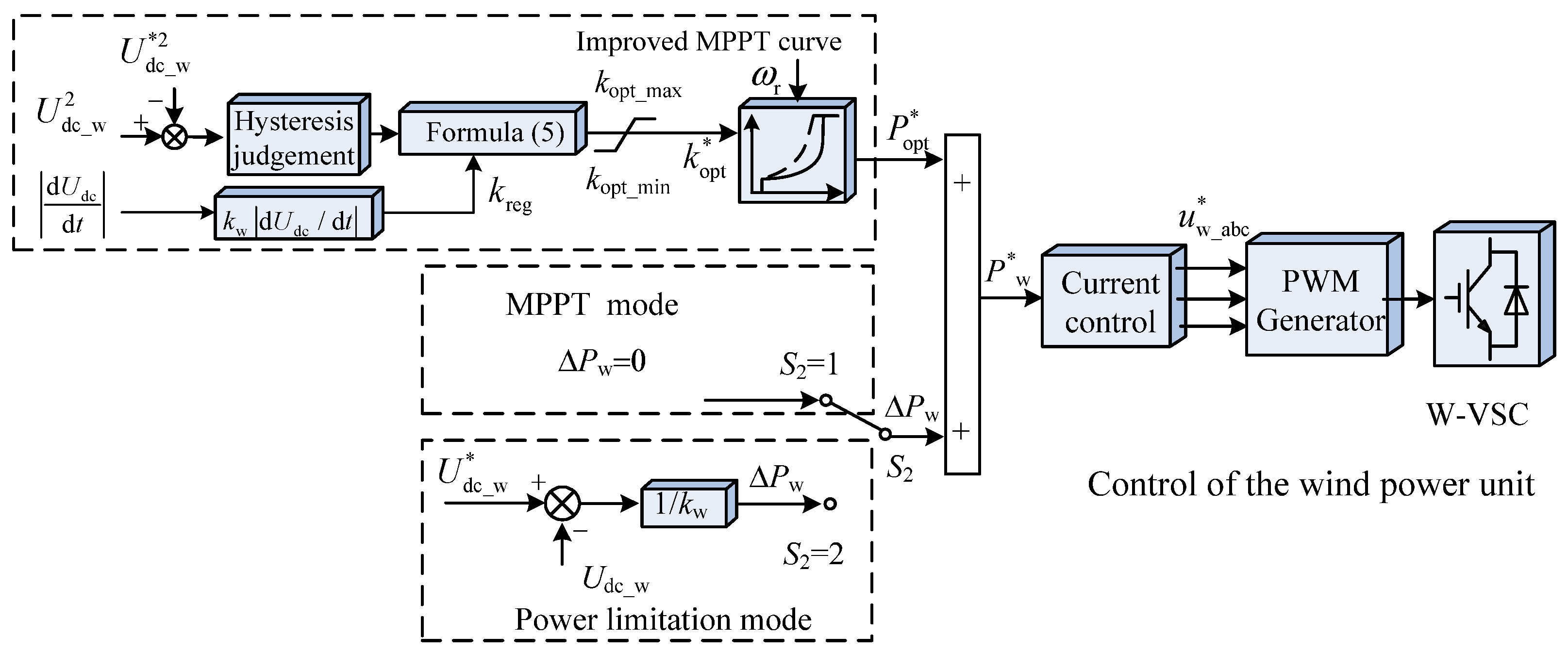
In the microgrid, DC voltage can reflect the power state, which determines the status of the criteria for system control. When the system maintains stable operation amidst minor power disturbances, the DC voltage exhibits minor fluctuations. Under this working condition, the wind power unit keeps performing maximum power point tracking (MPPT), while the energy storage unit is responsible for mitigating power disturbances by adjusting its charging power. In addition, as there is enough energy from the wind power/battery, the biomass power generation unit works in the standby state under this condition.
- (2)
Emergency mode
In case of an emergency, such as a failure in the wind power generation unit or a sudden decrease in wind speed with a low SOC of the batteries, the microgrid encounters huge power gaps, and the DC voltage may take on a step drop, which poses hazards to the voltage-sensitive supremacy drones. The biomass unit reacts rapidly to replenish the energy shortage to keep the stability of the system. Nevertheless, prior to the initiation of the biomass power generation unit, the power derived from the kinetic energy of wind turbines is utilized to temporarily mitigate power fluctuations, a topic that will be discussed in more detail in the subsequent section.
- (3)
Power limiting mode
In the mode of power limitation, the input from wind power exceeds the combined power requirements of the drones and the energy storage unit. And the withdrawal of the biomass power generation unit still cannot relieve the pressure of voltage rise. Under this circumstance, to ensure system stability, either the pitch angle control or speed control of the wind turbine will be implemented to decrease the wind power input or to temporarily store surplus power as kinetic energy.
- (4)
Load-shedding mode
In the event of prolonged power shortages, and the energy storage as well as the biomass unit are nearly depleted, the charging load of drones must be reduced based on priority through various control strategies.
4. Design of Master Controller Utilizing Model Predictive Control Techniques
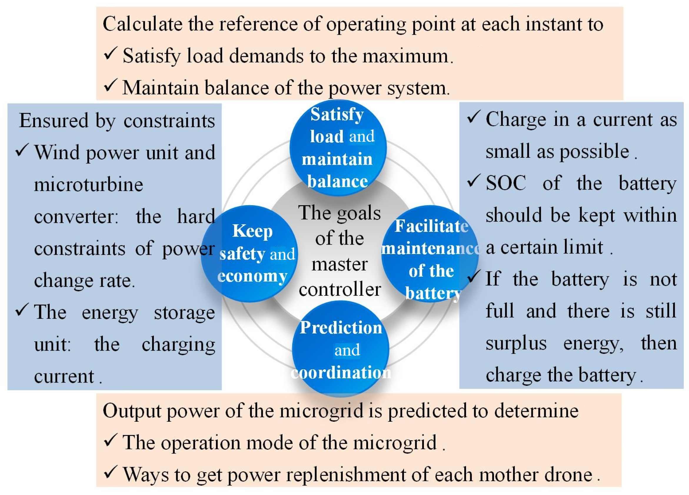
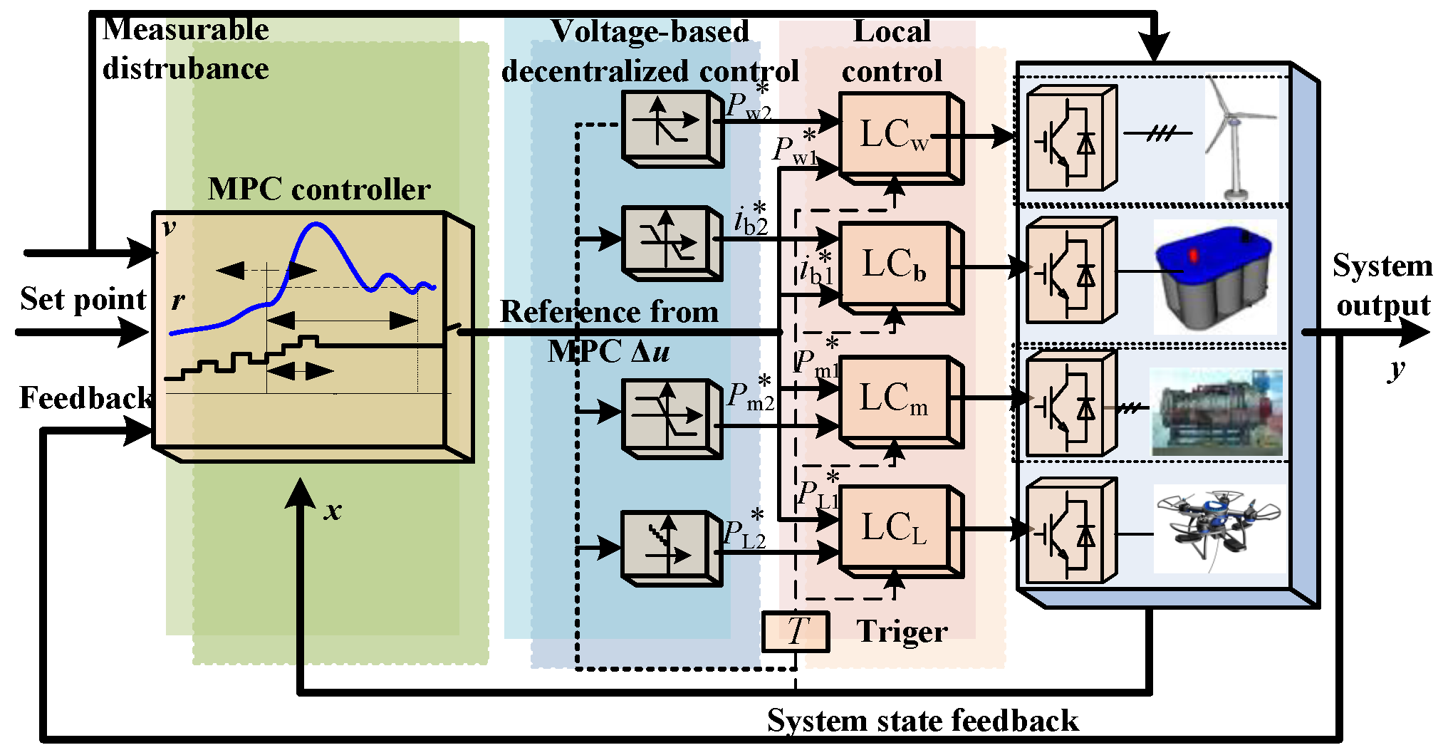
Compared with decentralized control methods, the model-based centralized predictive control method can accomplish many additional functions, such as energy management and economic operation management through the pre-definition and setting of functions. Furthermore, through the forecast and predictive information, the optimal control of the microgrid is realized so that the system operation is efficient and economical, rather than just realizing the power balance typical in decentralized control. The goals of the master controller design of the wind turbine DC microgrid are as depicted in
Figure 4.
During the normal operation of the microgrid system, state and forecast data are captured at every sampling interval and relayed to the master controller. Within this controller, the output trajectory over a predefined time horizon is forecasted using an internal system model. Subsequently, the optimal control sequence is determined by solving an optimization problem that minimizes the objective functions while adhering to operational constraints. The first element of this sequence is then implemented as the output for the control system.
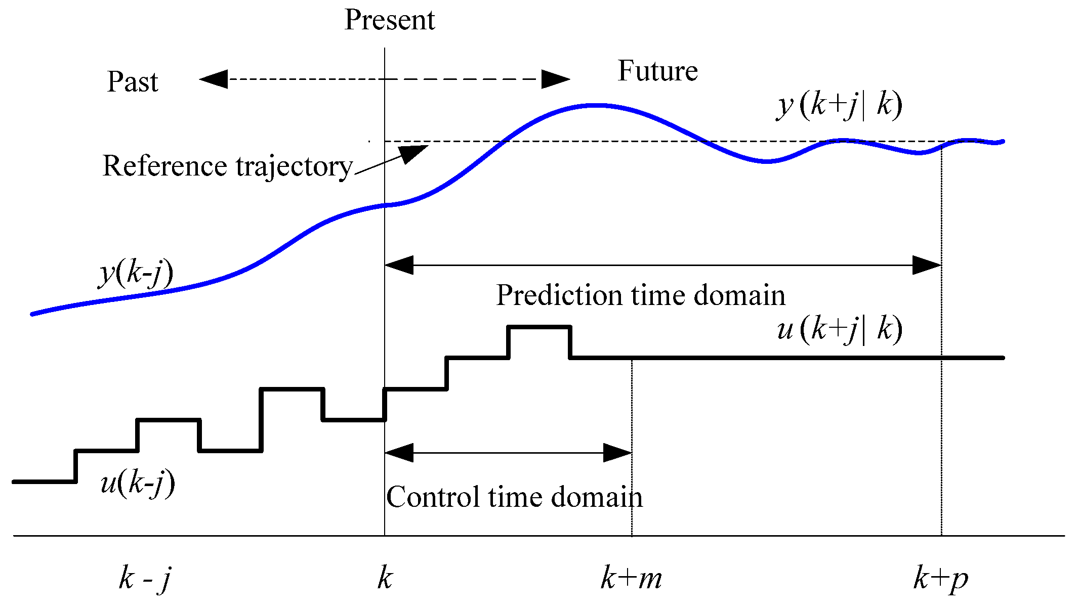
4.1. Prediction Model
In the model-predictive control process, predictive models are employed to forecast the process deviations within the projected time frame. The current optimal output for the controller is ascertained through a dynamic optimization approach, which is continuously updated as new data become available. The process is displayed in
Figure 5, where
u and
y denote the variables for process control as well as the system-controlled variables, time
k denotes the
k-th moment of sampling in the discrete system, and
u(
k +
j|
k) represents the predicted value of
u at the
k + j-th moment of sampling based on data available at time
k.
The prediction model adopts the state space equation shown in the following expression, which is a commonly utilized form.
where
x represents the state variables and
A,
B,
C, and
D correspond to the system matrix, input matrix, output matrix, and direct transmission matrix, respectively.
In free operation mode, the wind power generation unit employs the MPPT control to optimize the capture of wind energy. Any surplus energy is then allocated to the energy storage system. The power dispatch model for the wind power generation unit, along with its power limitations and rate-of-change constraints, is detailed below:
where
Pw denotes the output of the wind power unit while Δ
Pw signifies the rate of change.
Pw,max, Δ
Pw,max represent the upper bounds of
Pw and Δ
Pw, respectively, and
Pw,max, Δ
Pw,max denote the lower limits.
For the battery energy storage unit, its dynamic behavior is quantized into the subsequent formula.
where
Ts is the data acquisition interval.
Regarding the state of charge of the battery, Equation (7) yields the following result.
The limitations pertaining to the
SOC, along with the currents for charging and discharging, are delineated in inequalities (16) and (17).
where
SOCmax and
SOCmin denote the upper and lower thresholds of
SOC.
ib,max and
ib,min correspond to the upper and lower bounds of the currents during charging and discharging processes, respectively.
The vector of the system state variables, denoted as
x, comprises the elements [
Pw,
ib,
Pl,
vc,
SOC]
T. The system input is represented by
u, which is [Δ
Pw, Δ
ib, Δ
Pl]
T, and the system output is
y, which includes [
Pm,
Pw,
ib,
Pl,
SOC]
T. The matrices that represent the state space model are presented in the subsequent equations [
29]. As a per-unit system has been employed in the calculations for normalization purposes, the per-unit value of the voltage is equal to 1 at nominal conditions, making the current
ib numerically equivalent to the power of the battery system.
where
Pl represents the load, which are the UAVs in this paper.
4.2. Optimization Objective Functions of the System
Suppose that both the state and the disturbances of the system are known at time k. Then, the control variables at time k are capable of being determined by addressing the pre-established optimization problem.
The objective functions aligned with the design objectives (shown in
Figure 4), such as the balance, safety, efficiency, and battery maintenance of the microgrid, are presented in the following equation.
where
α,
β,
λ, and
ξ are the weighting factors for the subsequent corresponding expressions.
pr denotes the prediction time domain of the model.
Cwf stands for a constant.
x(
k +
j|
k) signifies the forecasted value of
x at instant
k +
j based on the information available at time k.
The initial term of the aforementioned function signifies that the battery should be charged if it is not already fully charged, while the second term aims to minimize the current used for charging. The third term encourages the wind power unit to operate under the MPPT control to maximize energy capture. The last item denotes that the three energy supply units and the load should ensure a balanced state of the system power to the maximum.
When the power demand of the mother drones is not large and the microgrid operates in free mode, the value of It is set to be 0, in which condition the wind power unit operates with the MPPT control to capture maximum wind power. As there is enough power provided by the wind turbine, the biomass unit works in standby. When there is a power deficiency in the system, the biomass unit should be connected rapidly to replenish the energy shortage. In this working condition, the value of It switches to 1 swiftly to maintain the power balance. On the contrary, when the power is superfluous, power balance should be maintained, with It being 1, and the pitch angle control or speed control of the wind turbine will be conducted.
The constrained optimization problem is shown in Formula (20), which aligns with the design objectives of the controller.
where
m is the time horizon for the control of the algorithm.
At time step k, the predicted output path within the forecasted time frame is determined using the established system model, taking into account both the current state and the anticipated future state. A multi-objective differential evolution algorithm is adopted to solve the optimization problem to obtain the most favorable solution that adheres to the constraints within the scope of the control period. The selection of weight coefficient values in Equation (19) is based on a set of predefined criteria that prioritize system performance. The first one of the solution {Δu(k|k), …, Δu(m – 1 + k|k)} is chosen as the outcome of the optimization process to generate the target values for each unit. As the sampling instant moves forward, the calculation process is repeated, and the optimizing correction is implemented in a rolling way to evolve into a closed-loop optimization.
6. Simulation Analysis
6.1. Main Settings of the Simulations
In order to verify the effectiveness of the proposed charging framework, as well as the improved distributed control of the microgrid, a simulation model of the charging system, including the wind power unit, biomass unit, battery, and UAV load, is established in MATLAB/Simulink with the structure being shown in
Figure 11. Simulations were conducted under the working conditions of moderate charging in free mode, charging in emergency mode, multiple charging with a variable load, and multiple charging with a malfunction in the biomass unit, respectively. The mother drones and the tethered drone chosen in this paper are small-sized drones, and the micro-sized drone was selected for the child drone. The main parameters of the system are listed in
Table 2.
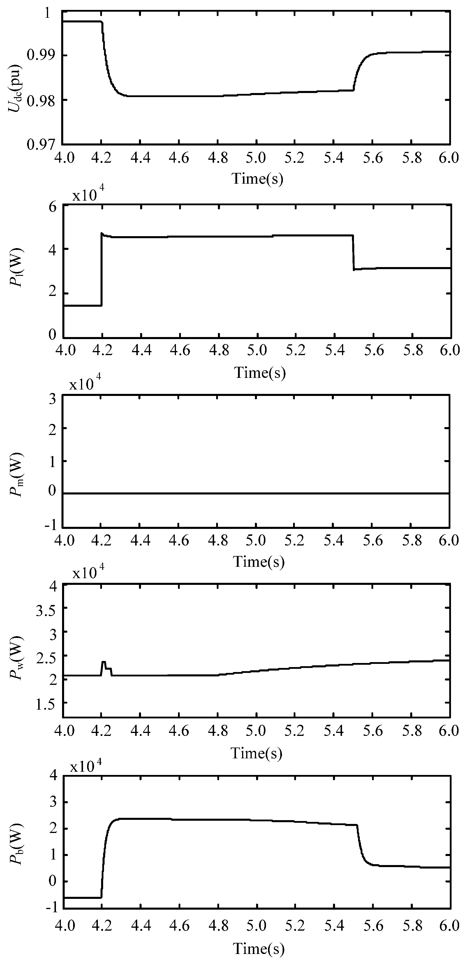
6.2. Simulation Study of Moderate Charging in Free Mode
As depicted in
Figure 11, the system maintains stable operation at the onset of the simulation, with the power demands of the drones hovering around 15 kW. At this time, the wind speed
v is 8 m/s, and the corresponding wind power is about 21 kW. As the deviation of DC voltage is within the specified range of the free mode, the battery is charged with a power of 6 kW. In this mode, the biomass power generation unit works in the standby state, and minor fluctuations in the system power are regulated by the energy storage unit.
At 4.2 s of the simulation, the load suddenly increases. The rotational kinetic energy of the wind turbine is rapidly released to smooth the DC voltage. With the joint effort of the energy storage and the wind turbine unit, the DC voltage is effectively prevented from further decreasing and is kept within the interval of [0.98, 1] pu. As there is no change in the operation mode, the biomass unit still works in the standby state. Starting at the 4.8-s mark of the simulation, the wind power begins to rise incrementally along with the wind speed, and the output of the energy storage unit decreases correspondingly to maintain the system balance. At the 5.5-s mark in the simulation, the overall power requests of the drones decrease. Correspondingly, the energy storage unit further reduces its output to fulfill the power demand.
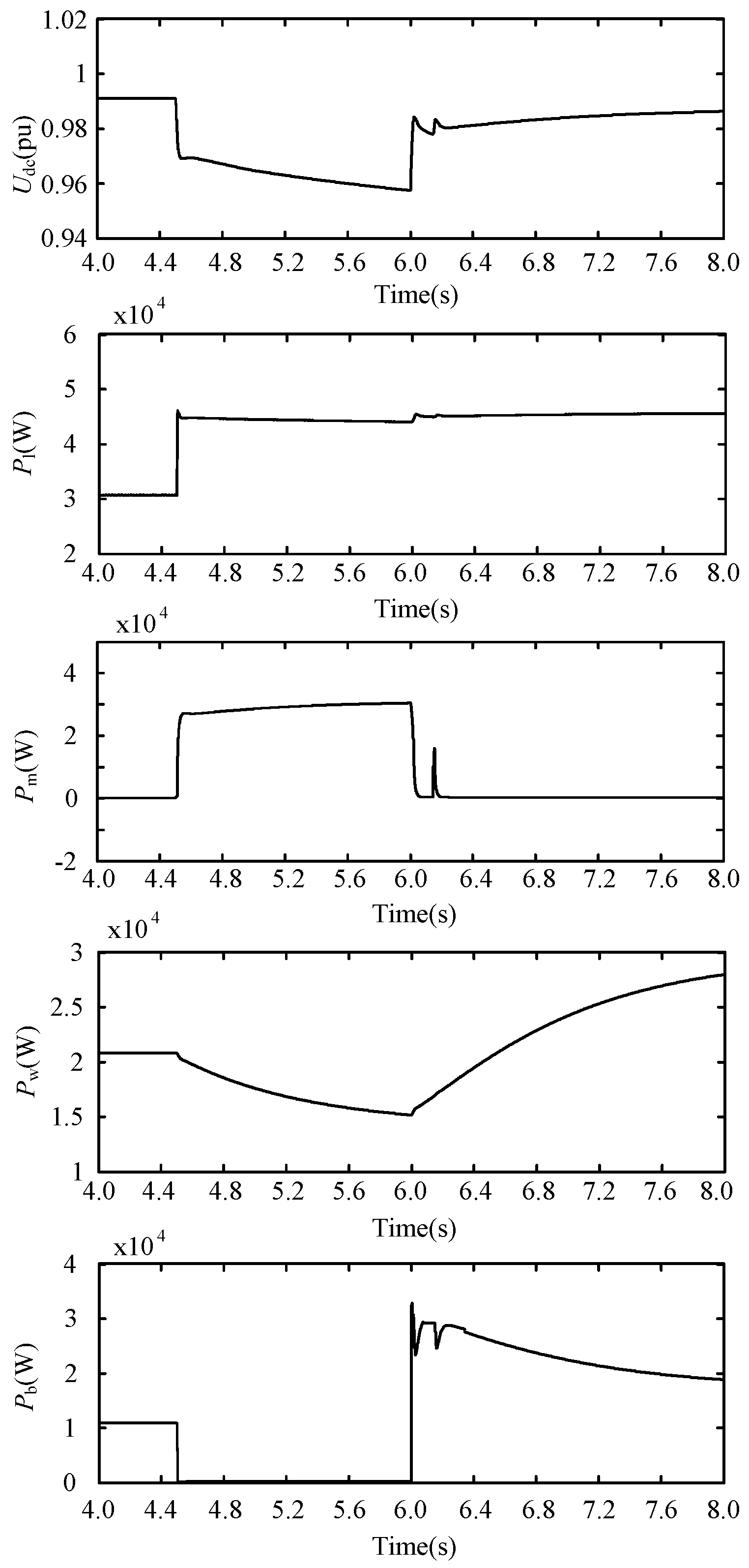
6.3. Simulation Analysis of Charging in Emergency Mode
As shown in
Figure 12, at the onset of the simulation, the system is in free mode, with the wind power unit producing the utmost power that corresponds to the prevailing wind speed. The energy storage unit replenishes energy deficiency, and the biomass unit works in the standby state.
At the moment of 4.5 s of the simulation, there is a sudden increase in the electricity demand of the drones, and a decrease in wind power output has exacerbated the power shortage in the system. Consequently, the DC voltage falls to the threshold for switching to emergency mode, which results in the start-up of the biomass power generation unit. In this condition, the biomass unit takes charge of system balance with its output power being about 28 kW, and the energy storage unit temporarily stops discharging. Under coregulation of the distributed units, balance of the system is quickly regained, with the DC voltage being maintained in a stable and controllable interval.
At the 6-s mark during the simulation, as the wind speed gradually recovers, the power supply of the system restores sufficiently. At this time, the system goes back to free mode, with the biomass unit exiting and the energy storage unit reacquiring the function of balance adjustment.
The power pulse of Pm at the instant of 6.1 s, shown in the figure, is caused by a voltage oscillation at the control threshold due to the rapid adjustment of the system.
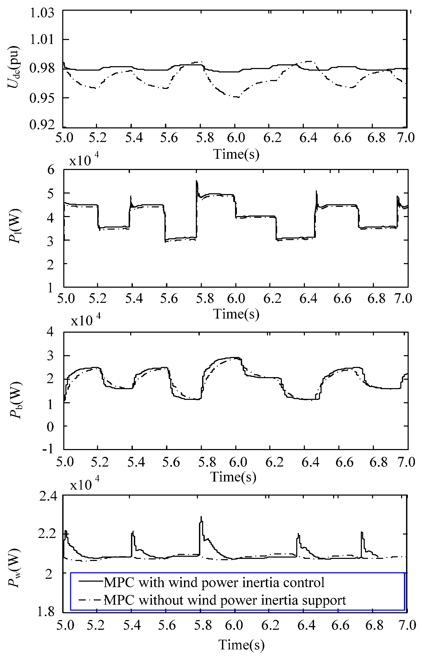
6.4. Simulation Analysis of Multiple Charging with Variable Load
The microgrid providing energy for aerial vehicles in a forest area is generally vulnerable to fluctuating power generated by the frequent access or withdrawal of several drones, particularly in cases where the biomass unit experiences malfunctions or runs out of fuel. The subsequent simulation illustrates the extreme scenario in which the output of the biomass unit is 0. MPC methods, with and without extra wind power inertia support, are adopted to exhibit the effect of utilizing the rotational kinetic energy of the wind turbine, as is shown by solid lines and dashed lines, respectively, in
Figure 13.
In scenarios where power regulation is undertaken without the inertial support of wind power, the system’s instantaneous fluctuations are managed exclusively by the energy storage unit. Despite the swift response to these variations in the energy storage unit, power fluctuations are still inevitable, and the DC voltage plummets to approximately 0.95 pu. Consequently, load shedding becomes an unavoidable measure until the voltage level is restored. In contrast, when predictive inertia support from wind power is incorporated, the wind turbine releases its rotational kinetic energy, offering an intermittent energy source that helps to smooth out power spikes. With the collaborative action of the battery and the wind turbine, the nadir of the voltage is elevated to around 0.97 pu, thereby ensuring energy reliability within the forest microgrid.
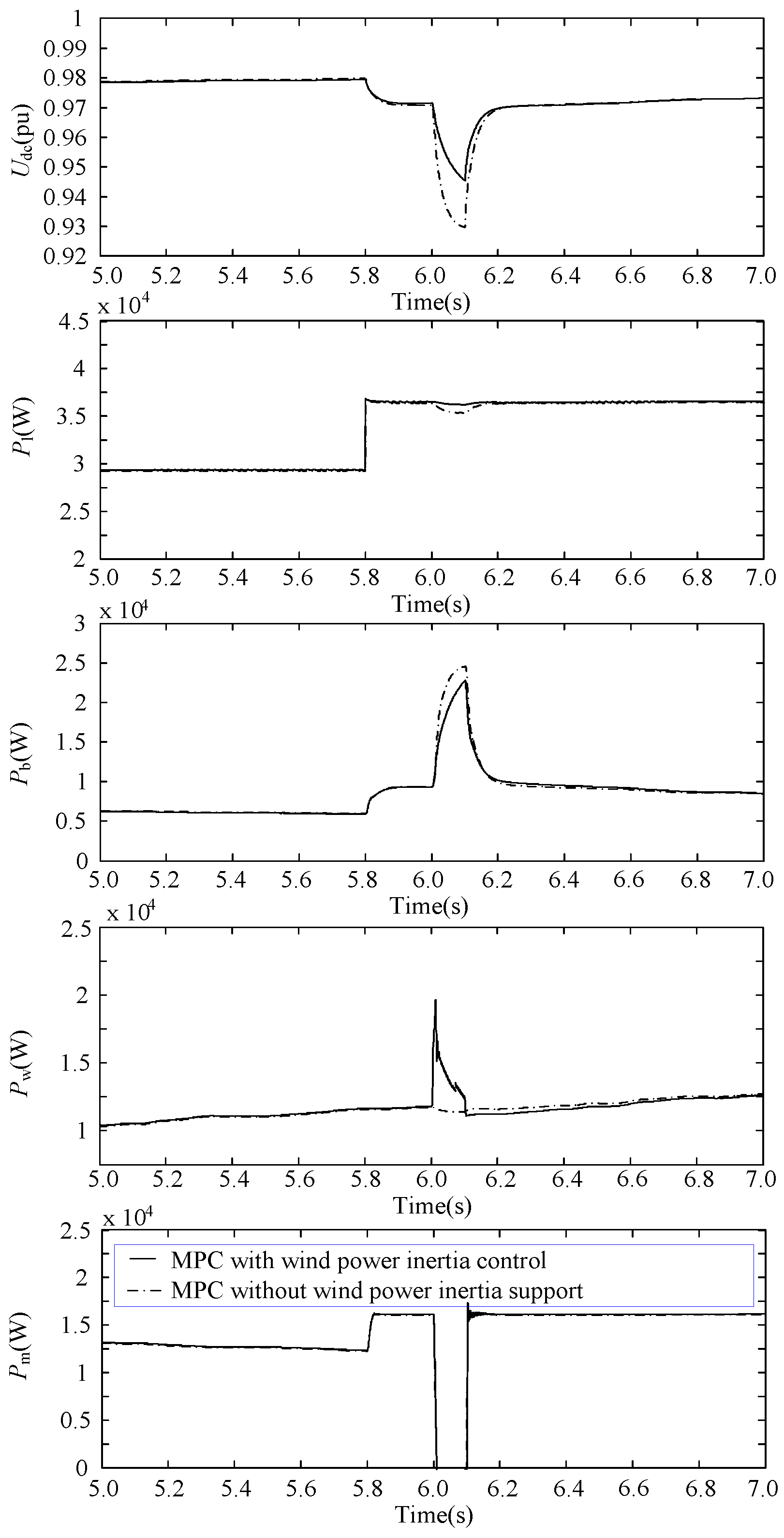
6.5. Simulation Analysis of Multiple Charging with Communication Fault
As shown in
Figure 14, before the moment of 5.8 s of the simulation, the microgrid operates stably. After a sudden rise in the multiple charging requirements of the drones, a power vacancy appears, which leads the DC voltage to fall lower. In this condition, the energy storage unit, which is also referred to as the energy buffer, takes charge of power regulation, and the biomass unit outputs constant power due to fuel limitation.
At the 6th second of the simulation, a fault emerges in the biomass power generation unit, causing a precipitous drop in its output power. At this juncture, the system faces a significant power shortfall. The responses of the microgrid units are depicted in the subsequent figures, where the dashed lines represent the operational trajectories when employing an MPC without wind power inertia support, and the solid lines signify those achieved with an MPC incorporating wind power inertia control.
When the MPC control without wind power inertia support is applied, the instantaneous power variations in the system are solely managed by the energy storage unit without any power contribution from the wind power unit. However, the increment of the battery power is insufficient to promptly bridge the substantial power gap, resulting in a sudden plunge of the DC voltage to 0.93 pu. As a result, load shedding is executed based on priority until the voltage recovers to 0.95 pu.
Upon the implementation of the supplementary speed control method, the rotor kinetic energy of the wind turbine is harnessed by reducing the mechanical speed, swiftly compensating for the power deficit in accordance with the voltage level and its rate of change. Concurrently, the energy storage unit escalates its power output, thereby mitigating the decline of DC voltage and elevating its nadir to a value exceeding 0.95 pu. Consequently, load shedding is circumvented, significantly enhancing the transient stability and the reliability of the power supply within the microgrid.
7. Conclusions
A novel comprehensive approach is proposed in this paper to enhance the transient stability and fault ride-through capacity of microgrids designed for the multiple charging needs of fire surveillance drones in vast forest areas. By leveraging the large rotating kinetic energy of wind turbines and employing a coordination control strategy with speed regulation, the ability to suppress power disturbances in a timely manner is successfully demonstrated. The model-based centralized predictive control method not only achieves power balance, which is typical of decentralized control, but also accomplishes additional functions such as energy and economic operation management through the pre-definition and setting of these functions. Utilizing forecast and predictive information, this method optimizes microgrid control, ensuring efficient and economical system operations.
In addition, a framework for charging systems of forest fire surveillance drones is outlined, in which a tiered charging infrastructure and a UAV replenishment strategy based on microgrids within forest regions are delineated to facilitate uninterrupted surveillance. The structure of the microgrid and its operational modes are proposed to accommodate diverse charging scenarios, followed by the detailing of the tiered charging framework for UAVs in forest microgrids, ensuring the continuity of surveillance efforts. The advanced coordination control strategy, incorporating wind turbine inertia regulation for the forest microgrid, is introduced as a pivotal component of the model predictive control method for power management within the microgrid. Simulations across various charging scenarios validate the effectiveness of the proposed method.
Several research challenges and considerations pertinent to the proposed charging framework are outlined. A key issue is determining the number and size of microgrids for vast forest areas, balancing monitoring precision with economic considerations. The development of efficient scheduling algorithms for UAV recharging is a critical topic that warrants discussion, aiming to optimize system performance. Furthermore, the exploration of secure and efficient recharging methods through airborne docking is necessary, and such methods should be integrated with scheduling strategies to ensure seamless surveillance across expansive forest areas. This research provides a foundation for future work in the field of UAV charging systems and their integration with microgrids for continuous forest fire surveillance.


