Abstract
The high penetration of renewable energy sources (RESs) and power electronics devices has led to a continuous decline in power system stability. Due to the instability of grid-following converters (GFLCs) in weak grids, the grid-forming converters (GFMCs) have gained widespread attention featuring their flexible frequency and voltage regulation capabilities, as well as the satisfactory grid-supporting services, such as inertia and damping, et al. Notably, the risk of wideband oscillations in modern power grids is increasingly exacerbated by the reduced number of synchronous generators (SGs). Thus, the wideband oscillation suppression method based on adaptive active power droop control of GFMCs is presented in this paper. First, the stability of the hybrid grid-forming and grid-following system is obtained according to the improved short circuit ratio (ISCR), where the GFMC is in parallel at the point of common coupling (PCC) of the GFLC. Then, an adaptive adjustment strategy of the active power droop control is proposed to enhance the oscillation suppression capability across the full frequency range, thereby mitigating the wideband oscillation caused by phase-locked loop (PLL) synchronization in the GFLCs. Additionally, a first-order inertia control unit is added to the active and reactive power droop controllers to mitigate frequency and voltage variations as well as suppress potential mid-to-high frequency resonance. Finally, the wideband oscillation suppression strategy is validated by the simulation and experimental results.
1. Introduction
With the increasing integration of renewable energy sources (RESs) through power converters, there has been a notable shift towards reducing reliance on fossil fuels [1,2]. However, this tendency leads to a decline in power system stability, as the traditional grid features enabled by synchronous generators (SGs) are replaced by a high penetration of power converters. The widespread adoption of power electronic devices has profoundly impacted the dynamic characteristics of the power system [3]. Weak inertia support from renewable energy generation, fluctuations and uncertainties in power transfer, regional coupling of converters and AC/DC interconnections, as well as negative damping characteristics introduced by the phase-locked loops (PLLs) in grid-following control, have triggered a series of risks associated with wideband oscillations [4]. As a result, the issue of wideband oscillations in power systems has attracted growing attention. Among these challenges, grid-connected converters for RESs lack synchronous inertia and are susceptible to negative damping effects due to PLLs, becoming a primary source of wideband oscillations. The mechanism and classification of wideband oscillations are illustrated in Figure 1, where the oscillations are generally composed of low-frequency, sub-synchronous, super-synchronous, and high-frequency oscillation [5,6].
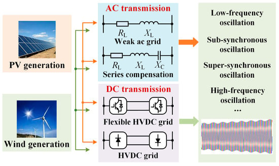
Figure 1.
Mechanism and classification of wideband oscillations.
In traditional power systems, SGs are capable of providing stable voltage support and essential grid services, including inertia and damping. In comparison, the mature control of grid-connected converters lacks these characteristics. Currently, two primary control technologies are employed for converters, including grid-following converters (GFLCs) and grid-forming converters (GFMCs) [7,8,9]. GFLCs connect to the grid by regulating the grid-injected current. They efficiently track the maximum power point, enabling high-efficiency power generation, delivering good power quality, and providing a fast response in power control. However, GFLCs exhibit weak voltage and frequency regulation capabilities, lack the ability to provide inertia, and heavily rely on synchronization units such as PLLs. As a result, they are prone to instability in weak grid conditions and face a heightened risk of oscillations under large disturbances. It is worth noting that grid-following control strategies based on PLLs reshape the impedance characteristics of the q-axis based on dq-frame control, causing negative impedance regions at low frequencies, which is a primary cause of power system instability induced by PLLs [4]. To overcome these inherent limitations, GFMCs have attracted widespread attention.
Specifically, GFMCs can provide flexible voltage and frequency regulation, explicit inertia, and broadband damping [10,11]. Unlike GFLCs, GFMCs do not rely on PLLs for grid synchronization, allowing them to seamlessly transition between islanded and grid-connected modes [7]. In extreme conditions, GFMCs support fault ride-through and black-start capabilities, enabling faster power restoration after grid failures. Additionally, GFMCs increase the short-circuit capacity of hybrid systems that integrate both grid-following and grid-forming technologies, enhancing the stability of power systems and effectively mitigating wideband oscillations [12,13,14].
Notably, some studies have introduced innovative designs to improve converter performance, enhance harmonic suppression, and increase system stability. Reference [15] presents a novel solution through a dual-purpose inverter in an AC/DC flyback converter. The key innovation lies in the integration of a dual-mode inverter, which functions as a harmonic filter under normal operating conditions. In the event of power outages, the inverter switches to backup mode, supplying sinusoidal voltage to maintain uninterrupted operation. In [16], an adaptive virtual impedance control has been proposed to suppress power oscillations and improve stability in multi-VSG grids, which also ensures stable power sharing and frequency response. However, these studies have not explored the impact of the coordinated operation of GFMCs and GFLCs on power system stability, which remains a critical issue to address in modern power-electronics-based grids.
Therefore, this article proposes a novel wideband oscillation suppression strategy based on adaptive active power droop control of GFMCs, where the stability enhancement of the hybrid system can be verified by the proposed improved short circuit ratio (ISCR). Further, we propose an adaptive adjustment strategy for the active power droop coefficient to enhance oscillation suppression across the full frequency range, mitigating the wideband oscillation caused by PLL synchronization in the GFLCs. In addition, we add a first-order inertia control unit to the active and reactive power droop controllers, further reducing frequency and voltage variations. By integrating and optimizing control of GFMCs, the strategy effectively mitigates oscillation risks and enhances the dynamic performance of power systems. The contributions of this article are concluded as follows:
- (1)
- Extracts ISCR to demonstrate that the stability of the hybrid system combining GFLCs and GFMCs has been improved.
- (2)
- Analyzes the mechanism by which the first-order inertia control unit enhances voltage transient stability.
- (3)
- Proposes the adaptive active power droop control strategy to enhance oscillation suppression capability.
The remainder of this article is organized as follows. Section 2 shows the system configurations of the hybrid grid-forming and grid-following systems, as well as the control structures. Section 3 gives a detailed description of the proposed ISCR and analyzes the stability of the hybrid systems. Section 4 proposes the wideband oscillation suppression strategy based on adaptive active power droop control of GFMCs, where the inertia control is also studied in detail. In Section 5, the wideband oscillation suppression strategy is validated by the simulations and experiments. Finally, Section 6 concludes this article.
2. System Configuration and Control Structure
The system configuration and control structure of the GFMC are illustrated in Figure 2, where the GFMC is integrated into the grid through the LCL filter, and in parallel with the grid-following system. The power grid is modeled as the serial connection of the equivalent grid inductance Ls and ideal voltage source vsabc. The LCL filter is composed of the converter-side inductance Lgi, filter capacitance Cgf, and grid-side inductance Lgg. Furthermore, igiabc and iggabc represent the converter-side currents and grid-injected currents, respectively. vgfabc denotes the capacitor voltages for voltage control. vdc stands for the DC-link voltage. In addition, pg and qg are the active and reactive power, transferring from the GFMC to the power grid. Notably, the grid-following system and the GFMC form a hybrid converter system by connecting at the Point of Common Coupling (PCC), which helps us explore the stability of the heterogeneous system.
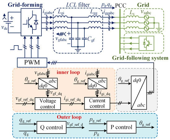
Figure 2.
System configuration and control structure of the hybrid grid-forming and grid-following system.
As shown in Figure 2, the control structure of the GFMC has also been constructed, including the inner-loop voltage control cascaded with current control (dual-loop), and the outer-loop power control. Notably, the subscripts d and q represent voltage and current variables in the synchronous dq-frame, and the subscript ref stands for the reference of variables. Furthermore, θg_ref and vgf_ref_d denote the phase angle and voltage reference generated by the active and reactive power control, respectively. In addition, the capacitor voltage and converter-side current are regulated in the inner-loop control and then produce the PWM modulation wave for power switches.
3. Principle of the Improved Short Circuit Ratio (ISCR)
3.1. Conventional Phase-Locked Loop for Grid-Following Converters
Accurate grid voltage information is essential for the proper regulation of grid-connected converters. Phase-angle extraction is typically accomplished using PLLs, where the structure schematic of the commonly-used PLL is depicted in Figure 3, which is also employed in GFLCs to synchronize with the grid for connection. Specifically, the phase coordinate transformation of grid-following control is achieved through locking the phase of the PCC voltages, thereby gaining high power factor transmission of current and active power.
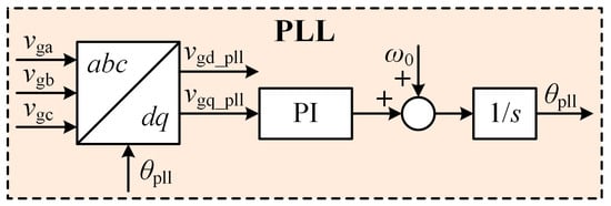
Figure 3.
Schematic diagram of a phase-locked loop.
It is noteworthy that the phase collected by the PLL cannot fully reflect the real grid phase information during dynamic adjustments of grid connection and control loops, the q-axis impedance will produce a negative damping characteristic in the low-frequency band of control loop, thereby posing a risk of wide-frequency oscillations in the system [4,17]. To address the instability issues introduced by PLLs, numerous solutions have been proposed, which primarily include two types of methods. The first type reduces the region of negative resistance by modifying the PLL design, while the other enhances stability by reshaping the impedance of adjacent grid-connected converters to suppress the torsional oscillations of the SGs. The approach proposed in this paper leans toward the latter.
3.2. The Proposed Improved Short Circuit Ratio (ISCR)
Generally, SCR is the ratio of the available short-circuit power at PCC to the rated power of the grid-connected power converter, indicating the strength and stability of the grid at that point. The system strength is defined as a weak grid when the SCR is less than 2, while the system is a strong grid when the SCR is larger than 3. The equivalent impedance model of the GFLC and voltage source has been illustrated in Figure 4, where Zg, ZL, and Zgi are the equivalent impedance of the grid, the filter inductor, and the GFLC, respectively. Notably, Zgi can be ignored since its impedance is usually quite large. Further, the SCR can be derived according to the equivalent impedance model, which is shown as
where Isc is the short-circuit current, S0 is the rated power of the power grid, and UN represents the rated voltage of the PCC.
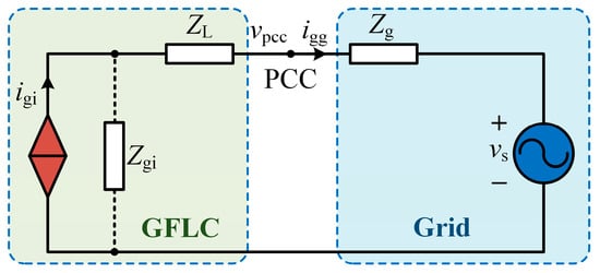
Figure 4.
The equivalent impedance model of the grid-following converter.
It is worth noting that the GFMC can be regarded as a controllable voltage source, as long as the capacitor voltages are stably controlled and regulated. Therefore, we illustrate the simplified system diagram of the GFMC in the hybrid system in Figure 5. Then, the ISCR of the GFLC can be derived, as follows.
where Sn is the rated power of the GFMC, and Isc1 and Isc2 are the short-circuit currents produced by the power grid and GFMC, respectively. USN represents the rated voltage of the power grid. In addition, Zg1 and Zg2 denote the equivalent impedance of the power grid and GFMC, respectively. SCR1 and SCR2 stand for the SCR generated by the ideal voltage source vsabc and the grid-forming system, respectively.

Figure 5.
The simplified system diagram of the grid-forming converter in the hybrid system.
Notably, the ISCR of the GFLC in the hybrid system is improved compared with the SCR of the specific grid-following system due to the additional SCR2 generated by the GFMC, which implies that the stability of the GFLC will increase in parallel with the GFMC. Although SCR1 changes with the dynamic variations in the grid’s equivalent impedance, it does not affect the criterion used by a traditional grid-following control to measure grid strength with the SCR. In addition, as the connection inductor Lgg of the GFMC is typically smaller than Ls, the SCR2 is often larger than SCR1. Therefore, in the modern power system, sufficient GFMCs are needed to enhance the grid strength. Meanwhile, the reasonable allocation of the GFMCs and GFLCs is required to achieve a balance between grid stability and the quality of the grid-injected current waveform [18]. It is worth noting that more GFMCs are not always better, as too many GFMCs will lead to instability.
4. The Proposed Wideband Oscillation Suppression Method Based on Adaptive Active Power Droop Control
In this section, we analyze the voltage inertia generated by the first-order low-pass filter unit of the reactive power droop control and propose an adaptive active power droop control method to suppress wideband oscillations.
4.1. The Inertia in the Droop Control
The droop control is often used in the academic and industry for the power controller and is easy to design owing to the first-order characteristic [19,20]. Further, the converter system will be stable when the equilibrium points exist. The block diagrams of the droop control are illustrated in Figure 6 and Figure 7, where s and ∆ represent the Laplacian complex variable and the parameter change, respectively. V0 and ω0 denote the rated voltage and rated angular frequency, respectively. In addition, Kpf and Kqv are the active and reactive power droop coefficients. Vgf_ref stands for the rated reference voltage. Therefore, the active and reactive droop control can be mathematically expressed as

Figure 6.
Block diagram of the active power droop control.

Figure 7.
Block diagram of the reactive power droop control.
Figure 8 depicts a simplified schematic of an infinite bus system with the GFMC and the grid. The GFMC is illustrated as a controllable AC voltage source, i.e., Vgf ∠ 0, where Vgf is the voltage amplitude and is selected as the reference of zero radian. The grid voltage is depicted as Vs ∠ −δg, where δg is the power angle between the two voltage sources. In addition, Igg ∠ φ represents the grid-injected current, and φ is the impedance angle. The dynamic behavior of transmission lines can be effectively modeled using a pure inductance, characterized by a line reactance denoted as Xgs. Therefore, the active and reactive power can be derived as
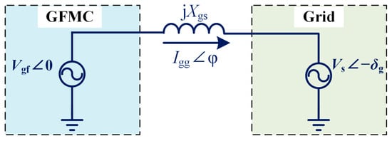
Figure 8.
Simplified schematic of the grid-forming converter and the grid.
Furthermore, we obtain (7) according to (4) and (6).
It is worth noting that the active power droop control with a series first-order inertia unit has been proven to be equivalent to the virtual synchronous machine (VSM). The added first-order inertia unit plays an inertial role in response to frequency changes. Similarly, reactive power droop control with a series first-order inertia unit also exhibits voltage inertia, which can smooth out voltage fluctuations. For better validation of voltage inertia, the expressions of reactive power and voltage with a first-order inertia unit and a PI controller have been derived as (8) and (9), according to Figure 9.
where ωc is the cutoff angular frequency of the first-order inertia unit, and kqp and kqi are the proportional and integral gains of the PI controller, respectively. Notably, the design of ωc is a tradeoff between power response speed and ripple rejection. We can design ωc based on the step response time requirements of reactive power and the requirements for suppressing the second harmonic ripple of reactive power according to the IEEE Std. 2800-2022 and National Grid ESO Grid Code [21,22]. We transform (8) and (9) into the time domain, as follows.

Figure 9.
Block diagram of the reactive power loop with droop + LPF controller and PI Controller.
As shown in Figure 10a, the curve of dVgfd/dt and Vgfd with reactive power control using a PI controller shows how the voltage changes during a fault. Typically, the curve has two equilibrium points: A is an unstable equilibrium, while B is a stable equilibrium. Further, Figure 10b depicts the curve with voltage inertia according to the time domain expression, which implies that the system has only one stable equilibrium point, when the capacitor voltage is greater than zero. Compared with Figure 10a, the transient stability is improved. Therefore, we can cascade a first-order low-pass filter in the feedforward path of traditional droop control to enhance the system’s transient stability.
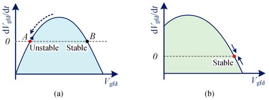
Figure 10.
Simplified dVgfd/dt and Vgfd curve of (a) the reactive power control with PI controller, (b) the reactive power droop control with voltage inertia.
4.2. The Proposed Wideband Oscillation Suppression Method Based on Adaptive Active Power Droop Control
The interaction between the GFMC with energy storage and the grid is crucial in maintaining stability and reliability, particularly under conditions of varying load demand and grid disturbances. The presence of the GFMC introduces enhanced control capabilities, allowing for precise regulation of voltage and frequency. This capability becomes pivotal in mitigating the impact of transient events and improving overall grid resilience. Moreover, recent studies underscore the importance of adaptive control strategies in managing the interaction between renewable energy sources. Adaptive control mechanisms facilitate real-time adjustments in response to changing grid conditions, thereby optimizing energy transfer efficiency and bolstering grid stability in the face of fluctuating renewable energy inputs.
The power angle curve has been illustrated in Figure 11 based on (5). After fault occurs, the system’s operating point goes through a process from A to C and then to A*, finally stabilizing at the newly established stable equilibrium point A*. Generally, most studies reduce the active power reference value to improve transient stability. However, it is worth noting that according to the relationship of the active power-frequency droop curve, reducing the active power reference value will inevitably lead to a slight decrease in system frequency (as droop control has a steady-state error), which will affect the safe and stable operation of the power system and increase equipment losses. Therefore, we designed an adaptive active power droop coefficient method to ensure system frequency stability.
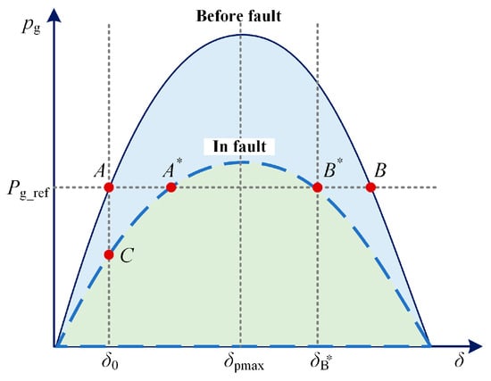
Figure 11.
Simplified pg and δ curve before and in fault.
The maximum value of pg can be determined from (5) when Vgf and Vs are stable.
The active power droop coefficient is typically obtained from the droop curve:
where ωmin is the required minimum angular frequency. In practical power systems, there are specific requirements for power quality, such as limiting frequency variations to within ±1%. Therefore, when designing the droop coefficient, it is necessary to consider an adaptive form.
The variables Vgf and Vs in the equation can be updated in real-time through sampling, while pg_ref can also be chosen as a suitable value to enhance system stability, as pg_ref is approximately equal to Sn when GFMC does not provide reactive power compensation, consequently allowing Kpf to be dynamically adjusted before the hybrid system stabilizes.
Figure 12 illustrates the schematic of the improved power controller proposed herein, incorporating a first-order low-pass filter and adaptive active power droop control. The first-order inertial unit in the active and reactive droop controllers is capable of attenuating frequency and voltage variations. The adaptive active power droop control adjusts dynamically according to (14), further enhancing system stability.
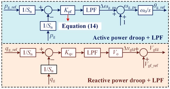
Figure 12.
The proposed adaptive active power droop control with the inertia units.
5. Simulation and Experimental Results
The simulation and experimental results for validating the adaptive active power droop control are shown in this section, where the parameters of the simulation are listed in Table 1.

Table 1.
Simulation parameters of the hybrid system.
5.1. Simulation Results
We conducted the simulations under the Matlab/Simulink (R2020a) environments. In Simulink, we built a simulation model of the hybrid system based on Figure 1, where the GFMC and GFLC are connected in parallel and then integrated into the power grid.
The simulation results of the grid-injected currents iggabc and the capacitor voltages vgfabc of the GFMC are illustrated in Figure 13. First, the GFLC is connected to the grid independently, when the current distortion can be observed along with some oscillation components. After 0.5 s, we connect the GFMC to the PCC. It is evident that the stability of the hybrid system has been significantly improved based on the proposed wideband oscillation suppression strategy with the grid-connected current being three-phase symmetric, and the waveform quality is better. Meanwhile, the capacitor voltages of the GFMC are controlled accurately. A zoom-in of simulation waveforms in Figure 13 is depicted in Figure 14, where the stable grid-injected currents as well as the capacitor voltages of the GFMC in the hybrid system exhibit strong sinusoidal characteristics. In addition, Figure 15 shows good simulated tracking results of the power in GFLC and GFMC before and after the GFMC is connected to the PCC.
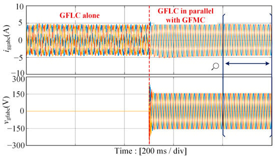
Figure 13.
Simulation waveforms of the grid-injected currents iggabc and the capacitor voltages vgfabc of the GFMC before and after connecting the GFMC with the proposed wideband oscillation suppression method.
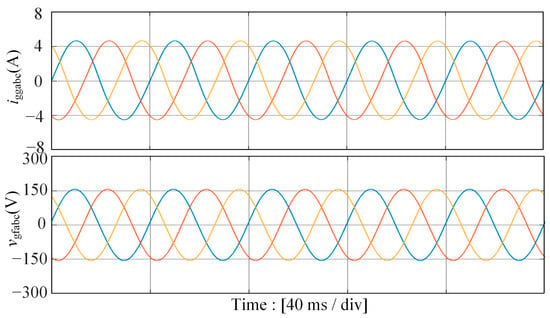
Figure 14.
Simulation waveforms of the stable grid-injected currents iggabc as well as the capacitor voltages vgfabc of the GFMC in the hybrid system.
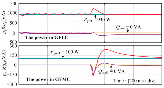
Figure 15.
The simulated results of the power in GFLC and GFMC before and after the GFMC is connected to the PCC.
Figure 16 depicts the simulated current spectrum of the grid-injected current before and after the GFMC is integrated into the grid. It can be observed that when the GFLC operates independently, multiple characteristic frequency ranges comprised of low-frequency, sub-synchronous frequency, and high-frequency oscillation components appear in the grid-injected currents due to the weak grid strength and the dynamic characteristics of the PLL. In comparison, after the GFMC is integrated into the system based on the proposed method, the suppression of oscillation components within a wide bandwidth range has been achieved, while the THD value of the grid-injected current rapidly decreases from 25.59% to 3.95%, which meets the requirements of the grid code, and the waveform quality is significantly improved. In this sense, we have verified the wideband oscillation suppression capability of the proposed method.
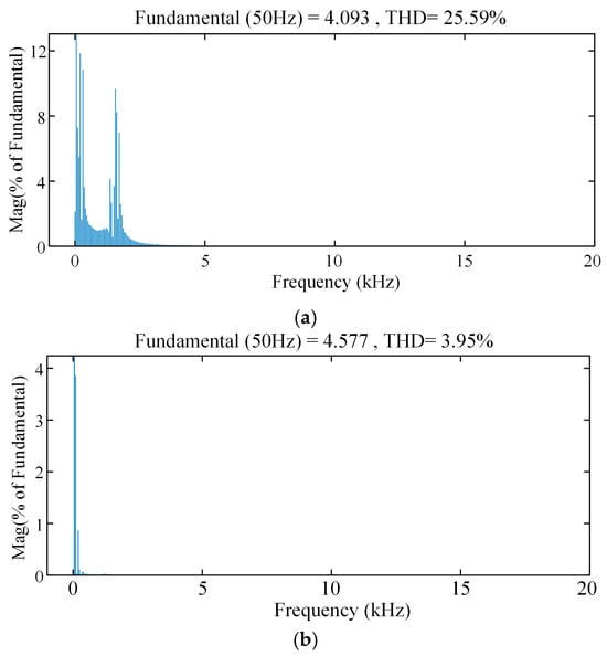
Figure 16.
Simulated current spectrums of the grid-injected current iggabc (a) before the GFMC connects to the grid, and (b) after the GFMC connects to the grid.
5.2. Experimental Results
We conducted experiments to further validate the proposed method, where the photo of the GFMC and GFLC is illustrated in Figure 17. The GFMC or GFLC consists of a digital signal processor (DSP) control board (TMS320F28379D), a sampling board (including 4 voltage and 4 current halls), et al. In addition, the grid is emulated by an AC programmable power supply (ITECH IT7625), while the GFLC and GFMC are fed by two DC power supplies (ITECH IT6526). The configuration of the GFLC, GFMC, and passive components in the experimental setup is the same as in the simulation, with only the voltage levels differing.
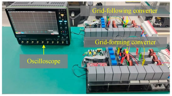
Figure 17.
Photo of the experimental setup.
The experimental results of the grid-injected current and PCC voltage with the GFLC operating independently and in parallel with the GFMC are shown in Figure 18 and Figure 19. As illustrated in Figure 18, the oscillatory instability occurred during grid connection by adjusting the proportional parameter of the PLL in GFLC, where the grid voltage is set as 30 V. In comparison, the experimental waveforms are stable and sinusoidal when the GFMC is connected to the PCC by setting a relatively small value of the active power reference, which validates the effectiveness of our proposed method.
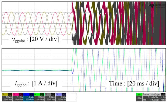
Figure 18.
Experimental results of the grid-injected current and PCC voltage with the grid-following converter operating independently.
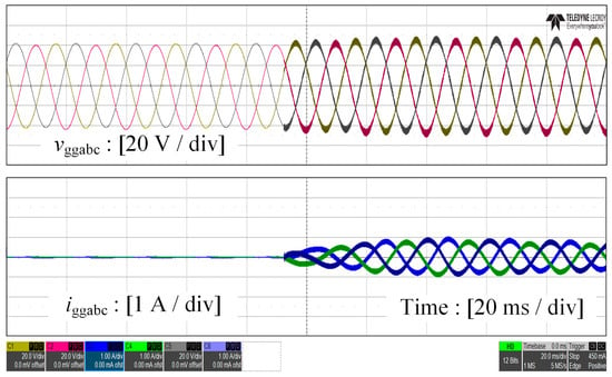
Figure 19.
Experimental results of the grid-injected current and PCC voltage with the grid-following converter parallel with the grid-forming converter based on the proposed method.
6. Conclusions
This article proposes a wideband oscillation suppression scheme based on the adaptive active power droop control of the GFMC, which aims at addressing the wideband oscillation issues in the grid-following system. By introducing the first-order inertial unit in the active and reactive power droop controllers and adjusting the active power droop coefficients adaptively, the transient stability of the system has been significantly improved, and the wideband oscillation issues have been effectively mitigated. Finally, simulation and experimental results verified the effectiveness of the proposed method.
Author Contributions
Conceptualization, L.Q. and J.F.; methodology, M.G.; software, Z.C.; validation, Z.D., Z.C. and M.G.; formal analysis, W.L.; investigation, L.Z.; resources, J.H.; data curation, L.Z.; writing—original draft preparation, W.L.; writing—review and editing, J.F.; visualization, J.H.; supervision, L.Q.; project administration, L.Q.; funding acquisition, L.Q. All authors have read and agreed to the published version of the manuscript.
Funding
This research was funded in part by the National Natural Science Foundation of China under Grant 52377192, Grant 20221017-9, and Grant 12411530110, in part by the Department of Science and Technology of Shandong Province under Grant ZR202210270088, in part by Jinan Science and Technology Bureau under Grant 202228069, in part by Guangdong Basic and Applied Basic Research Foundation under Grant 2022A1515110422, and in part by Shandong Provincial Universities under Grant 2022KJ007.
Data Availability Statement
The original contributions presented in the study are included in the article, further inquiries can be directed to the corresponding author.
Conflicts of Interest
Authors Lifeng Qiu, Miaosong Gu, Zhongjiang Chen, Zhendong Du, Ligang Zhang were employed by the company Zhejiang Huayun Electric Power Engineering Design & Consulting Co., Ltd. The remaining authors declare that the research was conducted in the absence of any commercial or financial relationships that could be construed as a potential conflict of interest.
References
- Carrasco, J.M.; Franquelo, L.G.; Bialasiewicz, J.T.; Galvan, E.; PortilloGuisado, R.; Prats, M.A.M.; Leon, J.I.; Moreno-Alfonso, N. Power-electronic systems for the grid integration of renewable energy sources: A survey. IEEE Trans. Ind. Electron. 2006, 53, 1002–1016. [Google Scholar] [CrossRef]
- Bragard, M.; Soltau, N.; Thomas, S.; De Doncker, R.W. The balance of renewable sources and user demands in grids: Power electronics for modular battery energy storage systems. IEEE Trans. Power Electron. 2010, 25, 3049–3056. [Google Scholar] [CrossRef]
- Fang, J. More-Electronics Power Systems: Power Quality and Stability; Springer: Berlin/Heidelberg, Germany, 2020; pp. 135–172. [Google Scholar]
- Fang, J.; Li, X.; Li, H.; Tang, Y. Stability improvement for three-phase grid-connected converters through impedance reshaping in quadrature-axis. IEEE Trans. Power Electron. 2018, 33, 8365–8375. [Google Scholar] [CrossRef]
- Chen, W.; Yang, Y.; Xie, Y.; Chang, X.; Lin, Y.; Yu, H.; Zhang, J. Subsynchronous oscillation mechanism of large-scale photovoltaic power generation connected to the grid through series compensation. Power Syst. Technol. 2021, 45, 4711–4721. [Google Scholar]
- Li, G.; Wang, W.; Guo, J.; Chen, X.; Liu, C.; He, G. Mechanism and analytical methods of wide-band oscillations in wind farms using MMC-HVDC transmission systems. Proc. CSEE 2019, 39, 5281–5297. [Google Scholar]
- Du, W.; Chen, Z.; Schneider, K.P.; Lasseter, R.H.; Nandanoori, S.P.; Tuffner, F.K.; Kundu, S. A comparative study of two widely used grid-forming droop controls on microgrid small-signal stability. IEEE J. Emerg. Sel. Top. Power Electron. 2020, 8, 963–975. [Google Scholar] [CrossRef]
- Pan, D.; Wang, X.; Liu, F.; Shi, R. Transient stability of voltage-source converters with grid-forming control: A design-oriented study. IEEE J. Emerg. Sel. Top. Power Electron. 2020, 8, 1019–1033. [Google Scholar] [CrossRef]
- Chen, M.; Zhou, D.; Blaabjerg, F. Enhanced transient angle stability control of grid-forming converter based on virtual synchronous generator. IEEE Trans. Ind. Electron. 2022, 69, 9133–9144. [Google Scholar] [CrossRef]
- Rosso, R.; Wang, X.; Liserre, M.; Lu, X.; Engelken, S. Grid-forming converters: Control approaches, grid-synchronization, and future trends—A review. IEEE Open J. Ind. Appl. 2021, 2, 93–109. [Google Scholar] [CrossRef]
- Awal, M.A.; Yu, H.; Lukic, S.; Husain, I. Droop and oscillator based grid-forming converter controls: A comparative performance analysis. Front. Energy Res. 2020, 8, 168. [Google Scholar] [CrossRef]
- Liu, P.; Xie, X.; Shair, J. Adaptive hybrid grid-forming and grid-following control of IBRs with enhanced small-signal stability under varying SCRs. IEEE Trans. Power Electron. 2024, 39, 6603–6607. [Google Scholar] [CrossRef]
- Wu, Y.; Wu, H.; Zhao, F.; Li, Z.; Wang, X. Influence of PLL on stability of interconnected grid-forming and grid-following converters. IEEE Trans. Power Electron. 2024, 39, 11980–11985. [Google Scholar] [CrossRef]
- Poolla, B.K.; Gros, D.; Dorfler, F. Placement and implementation of grid-forming and grid-following virtual inertia and fast frequency response. IEEE Trans. Power Syst. 2019, 34, 3035–3046. [Google Scholar] [CrossRef]
- Hoseini, S.M.; Sadeghzadeh, S.M.; Beromi, Y.A. A new method for active power factor correction using a dual-purpose inverter in a flyback converter. Turk. J. Electr. Eng. Comput. Sci. 2016, 24, 4736–4750. [Google Scholar] [CrossRef]
- Fu, S.; Sun, Y.; Li, L.; Liu, Z.; Han, H.; Su, M. Power oscillation suppression in multi-VSG grid by adaptive virtual impedance control. IEEE Syst. J. 2022, 16, 4744–4755. [Google Scholar] [CrossRef]
- Wen, B.; Boroyevich, D.; Burgos, R.; Mattavelli, P.; Shen, Z. Analysis of D-Q small-signal impedance of grid-tied inverters. IEEE Trans. Power Electron. 2016, 31, 675–687. [Google Scholar] [CrossRef]
- Yang, C.; Huang, L.; Xin, H.; Ju, P. Placing grid-forming converters to enhance small signal stability of PLL-integrated power systems. IEEE Trans. Power Syst. 2021, 36, 3563–3573. [Google Scholar] [CrossRef]
- Kawabata, T.; Higashino, S. Parallel operation of voltage source inverters. IEEE Trans. Ind. Appl. 1988, 24, 281–287. [Google Scholar] [CrossRef]
- D’Arco, S.; Suul, J.A. Equivalence of virtual synchronous machines and frequency-droops for converter-based microgrids. IEEE Trans. Smart Grid 2014, 5, 394–395. [Google Scholar] [CrossRef]
- IEEE Standard 2800-2022; IEEE Standard for Interconnection and Interoperability of Inverter Based Resources (IBRs) Interconnecting with Associated Transmission Electric Power Systems. IEEE: Piscataway, NJ, USA, April 2022; pp. 1–180.
- European Connection Conditions. National Grid ESO Grid Code. May 2023. Available online: https://www.neso.energy/document/287051/download (accessed on 17 October 2024).
Disclaimer/Publisher’s Note: The statements, opinions and data contained in all publications are solely those of the individual author(s) and contributor(s) and not of MDPI and/or the editor(s). MDPI and/or the editor(s) disclaim responsibility for any injury to people or property resulting from any ideas, methods, instructions or products referred to in the content. |
© 2024 by the authors. Licensee MDPI, Basel, Switzerland. This article is an open access article distributed under the terms and conditions of the Creative Commons Attribution (CC BY) license (https://creativecommons.org/licenses/by/4.0/).