Article

Recovering Low-Grade Heat from Flue Gas in a Coal-Fired Thermal Power Unit

1
State Key Laboratory of Low-Carbon Smart Coal-Fired Power Generation and Ultra-Clean Emission, Nanjing 210023, China
2
Guoneng Nanjing Electric Power Testing and Research Co., Ltd., Nanjing 210046, China
3
State Key Laboratory of Coal Combustion, Huazhong University of Science and Technology, Wuhan 430074, China
4
Guoneng Changzhou Secondary Power Generation Co., Ltd., Changzhou 213000, China
*
Author to whom correspondence should be addressed.
Energies 2024, 17(20), 5204; https://doi.org/10.3390/en17205204
Submission received: 13 September 2024 / Revised: 6 October 2024 / Accepted: 17 October 2024 / Published: 19 October 2024
(This article belongs to the Section B: Energy and Environment)

Abstract

:
To achieve the goals of carbon peaking and carbon neutrality, the retrofitting of existing coal-fired power plants is crucial to achieving energy-saving and emission reduction goals. A conventional recovery system of waste heat typically occurs downstream of the air preheater, where the energy quality in flue gas is low, resulting in limited coal-saving benefits. This study proposes a scheme involving a flue gas exchanger bypassing the air preheater and low-temperature economizers, which is used to transfer the waste heat from flue gas to primary and secondary air (System I). Additionally, a heat pump can be introduced to provide supplementary energy for primary and secondary air, as well as the condensate from the steam turbine (System II). The coal consumption rate and exergy efficiency are used to evaluate the two schemes. The results show that both waste heat recovery systems can increase the power output of the coal-fired unit by recovering waste heat. System II can boost power output by approximately 13.98 MW. The power increase in both waste heat recovery systems show a declining trend as the unit load decreases. This increased power is primarily attributed to the medium- and low-pressure cylinders, while the contributions from ultra-high-pressure and high-pressure cylinders are negligible. The increased power output for the medium-pressure cylinder ranges from approximately 3.49 to 3.58 MW, while the low-pressure cylinder has an increased power output of around 10.10 to 10.19 MW. The coal consumption rate is decreased from 250.3 g/(kW·h) to 247.5 g/(kW·h) under a full load condition for both systems, which can be augmented at lower load conditions. System II outperforms System I at 30% load condition, achieving a reduced coal consumption rate of 3.36 g/(kW·h). System I has an exergy efficiency of 40%, while System II shows a higher efficiency of 44%.

1. Introduction

To achieve peak carbon emissions and carbon neutrality, retrofitting existing coal-fired power plants is a crucial measure for enhancing energy conservation and reducing emissions, alongside the integration of renewable energy sources. For the coal-fired power plant, significant energy is lost due to the heat that escapes in the flue gas [1]. Recovering waste heat from flue gasses is one of the most effective ways to improve energy efficiency and reduce emissions in coal-fired power plants. Research shows that an increase of 10–15 °C in flue gas temperature results in a 1% decrease in boiler efficiency, which in turn raises the coal consumption rate of the power plant by 3–4 g/(kW·h) [2]. Therefore, minimizing flue gas heat loss is a highly effective approach to improving boiler efficiency, reducing carbon emissions, and supporting the objectives of carbon peaking and carbon neutrality.
Waste heat recovery technologies from flue gasses can be classified into two categories: direct utilization and waste heat upgrading technologies [3,4,5,6]. Direct utilization involves recovering waste heat through a heat exchanger, which is currently the primary method employed in power plants across China [7]. A common application of this technology is the use of low-temperature economizers to recover waste heat from flue gasses to preheat condensate water [8]. These economizers are usually installed downstream of the air preheater. Wang et al. [9] designed a waste heat recovery system that placed a low-temperature economizer between the electrostatic precipitator and the desulfurization unit, assessing its performance in a 600 MW unit. The results showed that this recovery system can reduce the coal consumption rate by 2–4 g/(kW·h). Zhang et al. [10] designed a novel waste heat recovery system. Their study showed that the exergy efficiency of the waste heat recovery system can reach 49.8%, and the coal consumption rate can be reduced by 4.75 g/(kW·h). Stevanovic et al. [11] studied a waste heat recovery system that combined high-temperature and low-temperature economizers, exploring their coupling with aging coal-fired power plants. They explored the impact of different flow arrangements on economizer performance. The results indicated that the lower inlet temperature of condensate water to the economizer resulted in higher heat transfer rates in the low-temperature economizer. Furthermore, they discovered that heating water with the high-temperature economizer after the feedwater pump was more effective than heating it at the high-pressure heater outlet. The system has the potential to increase the unit output by up to 26.1 MW and improve boiler efficiency by as much as 2.16%.
Waste heat upgrading involves the utilization of heat pumps to convert waste heat into medium or high-temperature heat, thereby enhancing the quality of the original heat for various applications [10,12,13,14,15,16,17,18]. This method addresses some of the challenges associated with the use of low-temperature flue gasses. Consequently, there has been significant academic interest in employing heat pumps for this purpose. Zhang et al. [19] designed a system that utilizes a heat pump driven by low-temperature flue gas, effectively recovering waste heat from flue gasses in coal-fired boilers. Their research results demonstrated an improvement in the coefficient of performance by 0.5% to 2.2%. Shahzad et al. [20] conducted a comparative analysis of the performance characteristics between double-stage open-cycle absorption heat pumps and single-stage systems, focusing on the influence of various intake parameters on energy absorption. Their findings showed that the double-stage system operated effectively at a lower driving heat source temperature (96.3 °C). Additionally, an increase in the low-pressure generator operating from 25 kPa to 35 kPa resulted in an enhancement in thermal performance by 8% to 11%. Wang et al. [6] developed a waste heat recovery system that integrates a condensing heat exchanger with an absorption heat pump, assessing its effectiveness in recovering high-humidity flue gasses. The results showed that the new system can reduce the flue gas temperature by 5 °C, recovering 81.4 t/h of water and 77.9 MW of waste heat.
This study focused on a 1000 MW unit and evaluated two types of waste heat recovery systems with flue gas bypass and heat pump individually and combined with the assistance of Ebsilon software 13.0. The incorporation of the heat pump into the flue gas bypass system is aimed to recycle more waste heat from the closed recirculation cooling water system of the power plant. System studies were conducted to explore the impact of integrating different waste heat recovery systems on the overall performance of the unit. Finally, the performance of the two waste heat recovery systems was evaluated.

2. System Introduction

2.1. The Introduction of Power Plant

The power plant studied in this work is a 1000 MW double-reheat ultra-supercritical unit with parameters of 32.55 MPa/610/625/625 °C. The boiler uses a four-compartment rotary air preheater. The turbine has an 11-stage regenerative extraction. The regenerative system includes 4 stages of high-pressure heaters, 1 deaerator, and 6 stages of low-pressure heaters.

2.2. Waste Heat Recovery System

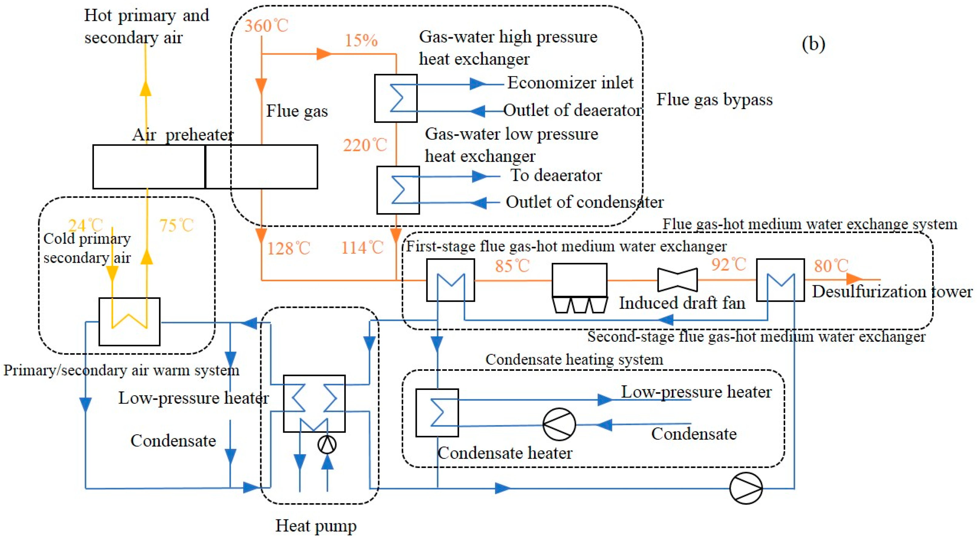
Two recovery systems of waste heat from flue gas are proposed. System I consists of a flue gas bypass component, a flue gas-hot medium water exchanger component, and an air heater component. The flue gas bypass component is engineered to recover relatively high-quality energy from flue gas bypassing the air preheater. This recovered energy is then transferred to the turbine through two exchangers. The flue gas bypass is divided into two stages. In the first stage, flue gas is directed through a gas–water high-pressure heat exchanger, which heats the feedwater existing in the deaerator before it enters the economizer. The second stage involves a gas–water low-pressure heat exchange that heats the condensate from the condenser, which is subsequently guided back into the deaerator after passing through the exchanger. Following the flue gas bypass component, the bypassed flue gas merges with the flue gas from the air preheater. The remaining thermal energy in flue gas is then transferred into a low-temperature exchanger component, which is composed of two-stage exchangers, as shown in Figure 1a. The low-temperature exchanger component is designed to recover thermal energy from flue gas to preheat the primary and secondary air, compensating for the bypass in flue gas. Initially, the flue gas passes through the first-stage flue gas-hot medium water exchanger, reducing its temperature to 85 °C prior to entering the electrostatic precipitator. To achieve further heat recovery, a second-stage flue gas-hot medium water exchanger is installed at the outlet of the induced draft fan, further lowering the flue gas temperature to 80 °C (considering a 7 °C temperature rise caused by the induced draft fan). Both stages of the flue gas-hot medium water exchanger utilize hot medium water as the heat transfer medium, effectively transferring waste heat from the flue gas to the primary and secondary air.
System II is based on System I by incorporating a heat pump. In this system, the thermal energy supplied by the flue gas-hot medium water economizer serves as the driving heat source for the heat pump. The heat source for the heat pump is derived from the closed recirculation cooling water system of the power plant. The thermal energy upgraded by the heat pump is transferred to an exchanger to elevate the temperature of cold primary and secondary air. Extra heat is used to heat the condensate water. As a result, additional thermal energy can be delivered to the condensate via the condensate heater, increasing power output. The system flow is illustrated in Figure 1b.

2.3. Evaluation Method

The coal consumption rate and thermal efficiency are used as evaluation indicators. The coal consumption rate is defined as the following formula [21]:
B = Q t η b q n e t P
P is the turbine power (kW); Qt is the energy in steam absorbed in the furnace (J/s); ηb is the boiler efficiency; and qnet is the heating value of standard coal (kJ/kg). For the calculation of the boiler thermal efficiency ηb, the boiler efficiency ηb varies compared to the original unit due to the effects of the flue gas bypass system. Here, the energy carried away by the flue gas bypass is all considered as flue gas heat loss. Additionally, due to the changes in the flue gas temperature at the air preheater outlet, the flue gas temperature is corrected according to the national standard GB/T 10184 [22].
t = t a . e n . d t f g . e n . m t f g . l v . m + t f g . e n . m t f g . l v . m t a . e n . m t f g . e n . m t a . e n . m
t a . e n . d is the design value of the air temperature at the air preheater inlet, °C; t f g . e n . m is the measured flue gas temperature at the air preheater inlet, °C; t f g . l v . m is the measured flue gas temperature at the air preheater outlet, °C; and t a . e n . m is the measured air temperature at the air preheater inlet, °C. After making the above corrections, the thermal efficiency of the boiler, incorporating the coupled waste heat recovery system, can be obtained. Subsequently, a performance calculation of the unit can be performed.
The exergy calculation method is calculated as follows [23]:
η e = E c 2 E c 1 E h 1 E h 2
E c 2 represents the exergy value of the heated fluid existing in the system, kW; E c 1 represents the exergy value of the heated fluid entering the system, kW; E h 2 represents the exergy value of the heating fluid existing in the system, kW; and E h 1 represents the exergy value of the heating fluid entering the system, kW.

3. Result and Discussion

3.1. Coal Consumption Rate Analysis

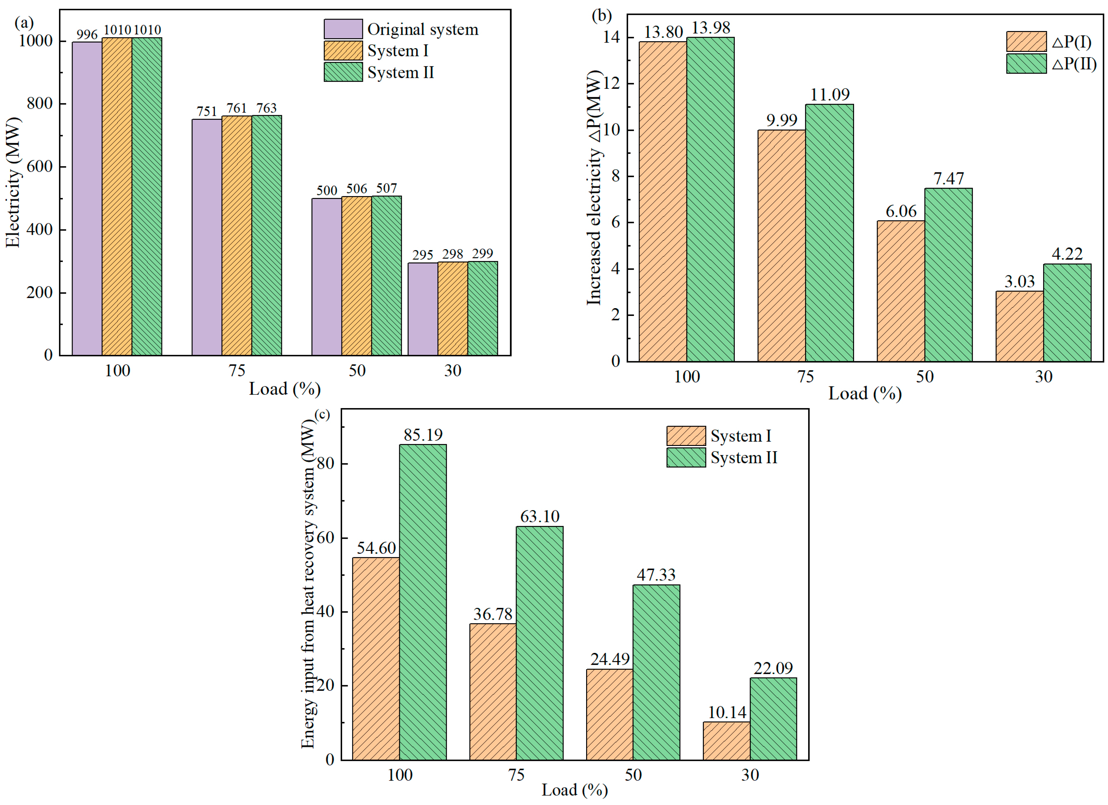
After equipping the unit with a waste heat recovery system, the variations in electrical power output are illustrated in Figure 2. As shown, System II exhibits an increase in the power output of 13.98 MW at full load, achieving a maximum output of 1010.2 MW compared to the original system. The additional power output from both systems diminishes with decreasing load due to the reduction in energy carried by the flue gas, which consequently lowers the energy recovered by the heat recovery system. Figure 2b demonstrates that the additional electrical power output of System II surpasses that of System I. For System I under full load, the energy transferred from the flue gas to the primary and secondary air accounts for 65.9% of the total energy in the flue gas entering the air preheater. Additionally, the energy recovered through the flue gas bypass accounts for 10.1% of the total. The energy directed to the turbine is approximately 54.6 MW, which generates 13.8 MW of electricity, resulting in an efficiency of 25.3%. Figure 2c indicates that System II recovers more energy for the turbine, enhancing electricity generation. System II employs medium water to drive a heat pump, bringing additional energy of 30.2 MW from the closed recirculation cooling water system of the power plant into the turbine. However, since the quality of energy after the heat pump upgrades is relatively low, limiting its ability to replace only the last stages of low-pressure steam extraction, this results in a lesser impact on overall power generation capability. Consequently, the observed difference in electrical power output is not as pronounced as the difference in recovered energy.
The impact of the waste heat recovery system on the coal consumption rate is shown in Figure 3a. The results indicate that both recovery systems can effectively reduce the coal consumption rate, lowering it from 250.3 g/(kW·h) to 247.5 g/(kW·h) under full-load conditions. However, as the load decreases, System II exhibits a more pronounced reduction in the coal consumption rate, achieving a decrease of up to 3.36 g/(kW·h). Figure 3b presents the variation in the coal consumption rate with the implementation of both recovery systems. As the load decreases, the disparity in coal savings between the two systems widens. Furthermore, coal savings from System I decline with decreasing load, whereas coal savings from System II increase, indicating that the energy-saving performance of System I deteriorates at lower loads while the performance of System II improves. This suggests that at low loads, the heat pump has a more significant impact on the performance of the recovery system.
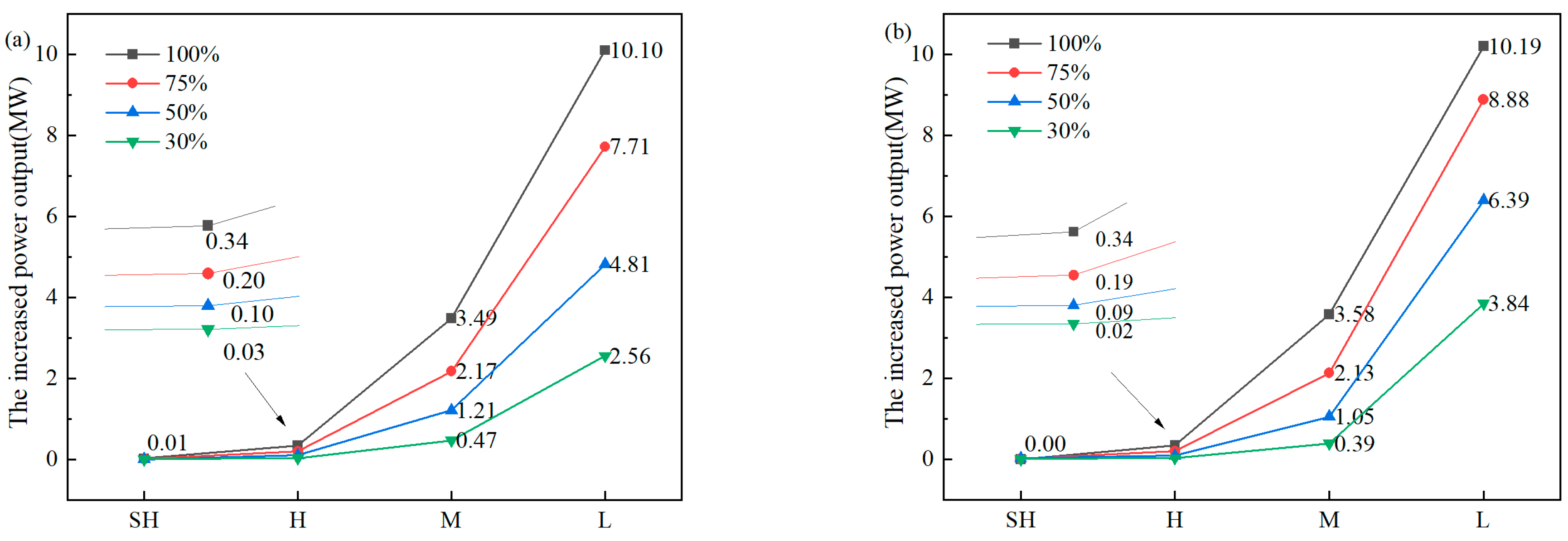
Figure 4 shows the increase in power output for each cylinder after the installation of two recovery systems under varying load conditions. Notably, System II demonstrates a slightly higher increase in power output compared to System I across all load scenarios. The super-high-pressure cylinder exhibits minimal change in power output due to the absence of extraction steam. Under high-load conditions, the power output of the high-pressure cylinder increases by 0.34 MW, while the power output of the medium-pressure cylinder rises between 3.49 and 3.58 MW. The low-pressure cylinder shows a more substantial increase, reaching up to 10.10–10.19 MW. This enhanced output primarily results from the recovery system displacing extraction steam, particularly affecting the final two stages of extraction in the medium-pressure cylinder and the fourth stage in the low-pressure cylinder. Comparative analysis of Figure 4a,b reveals how the decreasing trend in power output becomes more pronounced as the load decreases for both systems. Moreover, as the load decreases, the low-pressure cylinder experiences the most significant reduction in power output. In System II, the reduction in increased power output from the low-pressure cylinder occurs at a slower rate with decreasing load compared to System I. In System II, the energy output from the heat pump, except for heating the warm air, is utilized to heat the feedwater, which displaces the last two stages of extraction in the low-pressure cylinder, thereby enhancing its output. As the load decreases, the effect of additional energy from the heat pump becomes increasingly pronounced. Consequently, the reduction in power output for the low-pressure cylinder in System II is less significant than in System I.

3.2. Exergy Analysis

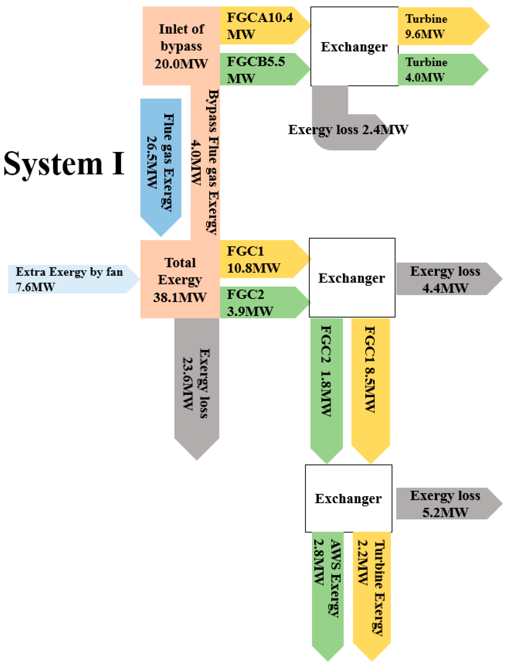
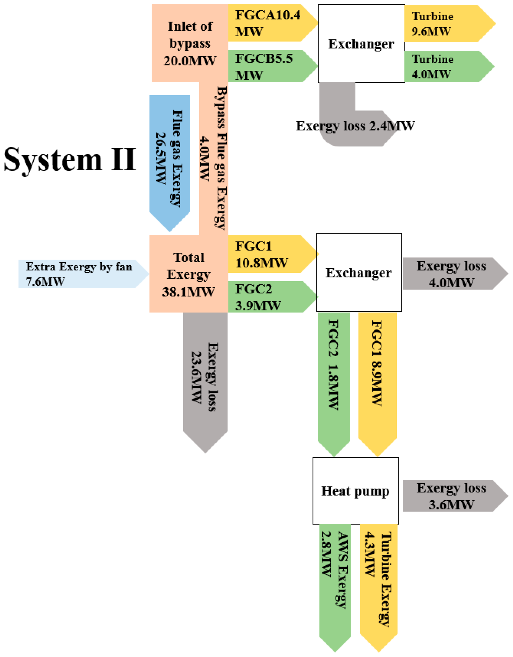
The installation of two bypass systems and a low-temperature waste heat recovery system is evaluated for total efficiency, as depicted in Figure 5. System I exhibits an exergy efficiency of 40%, whereas the exergy efficiency of System II is 44%. This means that System II can achieve a higher exergy efficiency compared to System I.
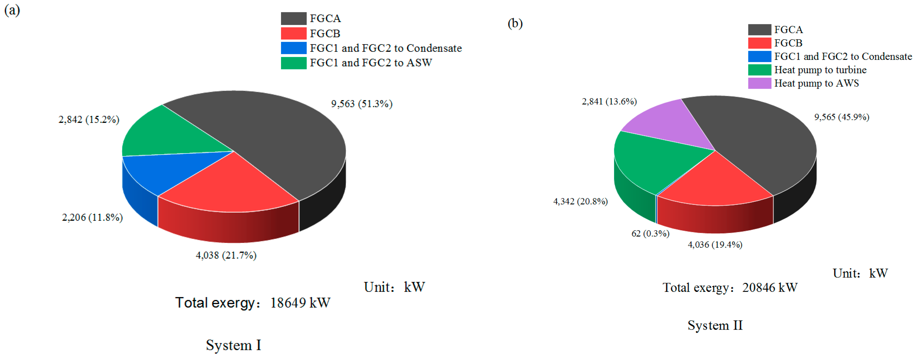
Figure 5 shows the exergy efficiency of various components of the recovery system. The efficiencies of FGCA, FGCB, FGC1, FGC2, and CHS show minimal variation. However, a significant difference is observed in AWS. In System I, the AWS is heated by the hot medium water from FGCA, which reaches a temperature of 117 °C. In contrast, System II employs a primary/secondary air heater that utilizes medium-temperature water (80 °C) from the heat pump. System II exhibits a smaller temperature difference in heat exchange, resulting in a higher efficiency of AWS. The distribution of recovered exergy for both recovery systems is shown in Figure 6. In System I, the recovered exergy via FGCA accounts for 51.3% of the total recovered exergy, whereas in System II, this figure is reduced to 45.9%. From the perspective of energy utilization, the design scheme that incorporates the air preheater bypass, supplemented by the air heater, demonstrates enhanced exergy efficiency in energy utilization.
The comparison of Figure 6a,b reveals that the total recycled exergy in System II is 20,845 kW, surpassing the 18,467 kW recycled by System I. This increase can be attributed to the implementation of heat pumps for generating medium-temperature water, which minimizes exergy losses. Additionally, System II benefits from the closed recirculation cooling water system compared to System I. Consequently, the heat pump recovery system in System II demonstrates superior exergy utilization in terms of both quantity and quality.
The exergy flows of the two recovery systems are shown in Figure 7 and Figure 8. It is evident that both systems experience a maximum exergy loss of 23.6 MW, primarily attributed to flue gas. In System I, the exergy loss in the flue gas-thermal medium water heat exchanger system is 9.6 MW. Low-temperature flue gas must first pass through the flue gas-thermal medium water heat exchanger, followed by thermal medium water-condensate and thermal medium water-warm air heat exchangers, before effective recovery can occur. This multistage heat exchange results in increased exergy loss. This configuration is implemented for safety reasons, as the relatively low flue gas temperature may lead to corrosion and damage to heat exchange surfaces if it drops below the acid dew point due to load fluctuations. Such corrosion can contaminate water quality and jeopardize the safety of water circulation. Reducing the indirect heat exchange process while ensuring safety is an effective method for enhancing system efficiency and overall energy utilization. In contrast, System II exhibits a lower exergy loss of 7.6 MW in its flue gas-thermal medium water heat exchanger, suggesting that the heat pump system contributes to reduced exergy loss compared to System I.

4. Conclusions

This study developed two types of waste heat recovery systems and investigated the impact of different recovery systems on the overall performance of the unit. The main conclusions are as follows:
(1)
Both waste heat recovery systems can increase the output of the unit, reduce coal consumption, and improve the energy utilization efficiency of the equipment by recovering waste heat. System II can boost power output by up to 13.98 MW while reducing the coal consumption rate by up to 3.36 g/(kW·h), showcasing significant energy-saving benefits.
(2)
The increase in power output due to the waste heat recovery systems decreases as the unit load reduces. Additionally, the increased power output is mainly distributed in the medium- and low-pressure cylinder sections, with minimal impact on supercritical and high-pressure cylinders.
(3)
From the perspective of energy utilization efficiency, System II has a better exergy utilization efficiency, achieving an exergy efficiency of 44% with a recovery amount of 20,845 kW. The primary thermal loss in the waste heat recovery system stems from flue gas heat loss. However, due to corrosion issues caused by flue gas temperatures reaching the acid dew point, further utilization of low-temperature heat is challenging. The heat pump system can reduce thermal losses. Corrosion problems arising from flu-gas temperatures hitting the acid dew point complicate the further use of low-temperature heat. Implementing a heat pump system can help minimize these thermal losses.

Author Contributions

Validation, L.H.; Investigation, X.X.; Resources, G.C., R.T. and H.Z.; Supervision, J.Y.; Funding acquisition, X.G. All authors have read and agreed to the published version of the manuscript.

Funding

This research received no external funding.

Data Availability Statement

The original contributions presented in the study are included in the article, further inquiries can be directed to the corresponding author.

Conflicts of Interest

Authors Linbin Huang and Guoqing Chen were employed by the company State Key Laboratory of Low-Carbon Smart Coal-Fired Power Generation and Ultra-Clean Emission. Author Rui Tan was employed by Guoneng Nanjing Electric Power Testing and Research Co., Ltd. Authors Xinglong Gao and Haifeng Zhang were employed by Guoneng Changzhou Secondary Power Generation Co., Ltd. The remaining authors declare that the research was conducted in the absence of any commercial or financial relationships that could be construed as a potential conflict of interest.

Abbreviations

FGCAgas–water high-pressure heat exchanger
FGCBgas–water low-pressure heat exchanger
FGC1first-stage flue gas-hot medium water exchanger
FGC2second-stage flue gas-hot medium water exchanger
CHScondensate heat system
AWSair warm system
HPheat pump
Symbols
Bcoal consumption rate
Pturbine power (kW)
Qtenergy in steam adsorbed in the furnace (J/s)
ηbboiler efficiency
qnetheating value of standard coal (kJ/kg)
t a . e n . d design value of air temperature at air preheater inlet
t f g . e n . m measured flue gas temperature at air preheater inlet
t f g . l v . m measured flue gas temperature at air preheater outlet
t a . e n . m measured air temperature at air preheater inlet
η e exergy efficiency
E c 2 exergy value of heated fluid existing system
E c 1 exergy value of heated fluid entering system
E h 2 exergy value of heating fluid existing system
E h 1 exergy value of heating fluid entering system

References

  1. Fu, C.; Anantharaman, R.; Jordal, K.; Gundersen, T. Thermal efficiency of coal-fired power plants: From theoretical to practical assessments. Energy Convers. Manag. 2015, 105, 530–544. [Google Scholar] [CrossRef]
  2. Chao, L.; Ke, L.; Yongzhen, W.; Zhitong, M.; Yulie, G. The Effect Analysis of Thermal Efficiency and Optimal Design for Boiler System. Energy Procedia 2017, 105, 3045–3050. [Google Scholar] [CrossRef]
  3. Xiao, P.; Zhang, Y.; Wang, Y.; Wang, J. Analysis of an improved economizer system for active control of the coal-fired boiler flue gas temperature. Energy 2019, 170, 185–198. [Google Scholar] [CrossRef]
  4. Xu, G.; Xu, C.; Yang, Y.; Fang, Y.; Li, Y.; Song, X. A novel flue gas waste heat recovery system for coal-fired ultra-supercritical power plants. Appl. Therm. Eng. 2014, 67, 240–249. [Google Scholar] [CrossRef]
  5. Yang, Y.; Xu, C.; Xu, G.; Han, Y.; Fang, Y.; Zhang, D. A new conceptual cold-end design of boilers for coal-fired power plants with waste heat recovery. Energy Convers. Manag. 2015, 89, 137–146. [Google Scholar] [CrossRef]
  6. Wang, X.; Zhuo, J.; Liu, J.; Li, S. Synergetic process of condensing heat exchanger and absorption heat pump for waste heat and water recovery from flue gas. Appl. Energy 2020, 261, 114401. [Google Scholar] [CrossRef]
  7. Wei, M.; Zhao, X.; Fu, L.; Zhang, S. Performance study and application of new coal-fired boiler flue gas heat recovery system. Appl. Energy 2017, 188, 121–129. [Google Scholar] [CrossRef]
  8. Xu, G.; Huang, S.; Yang, Y.; Wu, Y.; Zhang, K.; Xu, C. Techno-economic analysis and optimization of the heat recovery of utility boiler flue gas. Appl. Energy 2013, 112, 907–917. [Google Scholar] [CrossRef]
  9. Wang, C.; He, B.; Sun, S.; Wu, Y.; Yan, N.; Yan, L.; Pei, X. Application of a low pressure economizer for waste heat recovery from the exhaust flue gas in a 600 MW power plant. Energy 2012, 48, 196–202. [Google Scholar] [CrossRef]
  10. Zhang, G.; Zhang, S.; Sun, B.; Liu, J.; Yan, J. Design on a novel waste heat recovery system integrated with the bypass flue and outside primary air preheater for bitumite-fired power plants. Energy 2024, 291, 130341. [Google Scholar] [CrossRef]
  11. Stevanovic, V.D.; Petrovic, M.M.; Wala, T.; Milivojevic, S.; Ilic, M.; Muszynski, S. Efficiency and power upgrade at the aged lignite-fired power plant by flue gas waste heat utilization: High pressure versus low pressure economizer installation. Energy 2019, 187, 115980. [Google Scholar] [CrossRef]
  12. Yang, B.; Yuan, W.; Fu, L.; Zhang, S.; Wei, M.; Guo, D. Techno-economic study of full-open absorption heat pump applied to flue gas total heat recovery. Energy 2020, 190, 116429. [Google Scholar] [CrossRef]
  13. Han, Y.; Xu, G.; Zheng, Q.; Xu, C.; Hu, Y.; Yang, Y.; Lei, J. New heat integration system with bypass flue based on the rational utilization of low-grade extraction steam in a coal-fired power plant. Appl. Therm. Eng. 2017, 113, 460–471. [Google Scholar] [CrossRef]
  14. Yan, M.; Zhang, L.; Shi, Y.; Zhang, L.; Li, Y.; Ma, C. A novel boiler cold-end optimisation system based on bypass flue in coal-fired power plants: Heat recovery from wet flue gas. Energy 2018, 152, 84–94. [Google Scholar] [CrossRef]
  15. Faraji, H.; Faraji, M.; El Alami, M. Numerical Survey of the Melting Driven Natural Convection Using Generation Heat Source: Application to the Passive Cooling of Electronics Using Nano-Enhanced Phase Change Material. J. Therm. Sci. Eng. Appl. 2019, 12, 1–17. [Google Scholar] [CrossRef]
  16. Yang, M.; Zhou, Y.; Yang, J.; Bao, J.; Wang, D.; Yu, Q. Performance analysis of an efficient waste heat utilization system in an ultra-supercritical coal-fired power plant. Energy Rep. 2022, 8, 5871–5882. [Google Scholar] [CrossRef]
  17. Chen, X.; Xu, S.; Yang, Y.; Wang, L.-M.; Wang, D.-D. Performance Analysis and Optimization of Flue Gas Waste Heat Recovery System of a 600MW Coal-Fired Power Plant. In Proceedings of the ASME 2020 Power Conference Collocated with the 2020 International Conference on Nuclear Engineering, ASME 2020 Power Conference, Virtual, 4–5 August 2020. [Google Scholar]
  18. Du, X.; Bai, R.; Sang, P.; Fang, L.; Shi, Y. Experimental and simulation study on optimal operation of flue gas waste heat utilization system of coal-fired unit. J. China Coal Soc. 2023, 48, 2682–2690. [Google Scholar]
  19. Zhang, H.; Dong, Y.; Lai, Y.; Zhang, H.; Zhang, X. Waste heat recovery from coal-fired boiler flue gas: Performance optimization of a new open absorption heat pump. Appl. Therm. Eng. 2021, 183, 116111. [Google Scholar] [CrossRef]
  20. Kashif Shahzad, M.; Ding, Y.; Xuan, Y.; Gao, N.; Chen, G. Performance analysis of a novel double stage multifunctional open absorption heat pump system: An industrial moist flue gas heat recovery application. Energy Convers. Manag. 2022, 254, 115224. [Google Scholar] [CrossRef]
  21. Yong, L.; Yanhong, W.; Beingwen, Z. Correction of boiler thermal efficiency and standard coal consumption rate based on different standards. J. Chin. Soc. Power Eng. 2012, 32, 273–281. [Google Scholar]
  22. GB/T 10184—2015; Performance Test Code for Utility Boiler. China Standards Press: Beijing, China, 2015.
  23. Juan, Y.; Jianfeng, L.; Juan, W.; Ziyuan, Z.; Guitao, P.; Ma, Q.; Chu, J. Research on Retrofit Scheme of Ultra-high Heating Load of Coal-fired Units. J. Electr. Power 2022, 37, 287–297. [Google Scholar]
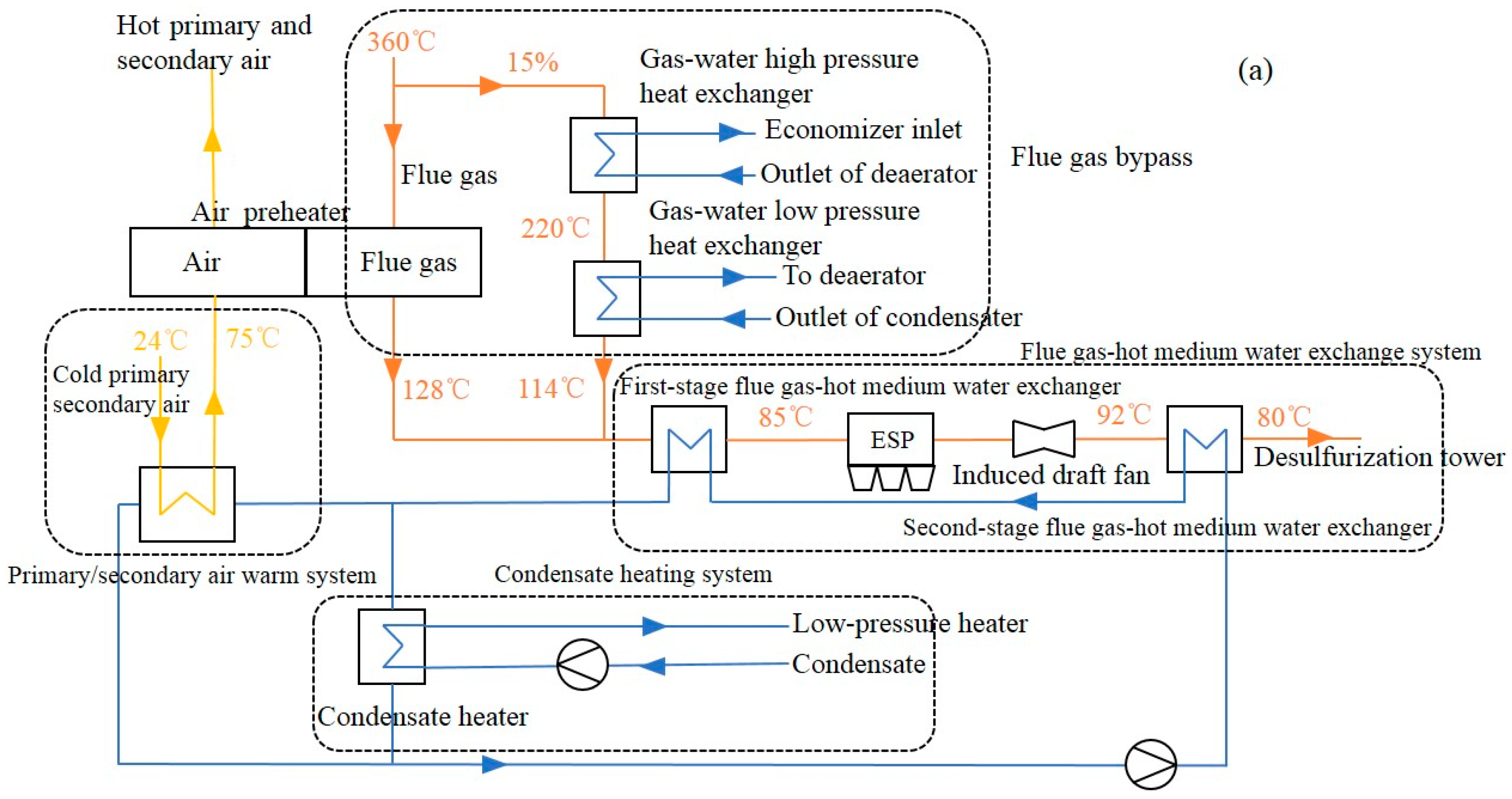
Figure 1. The design of the flue gas heat recovery system. (a) System I (b) System II.
Energies 17 05204 g001aEnergies 17 05204 g001b
Figure 2. The change in electricity with flue gas heat recovery. Load: power output. (a) Total electricity generation. (b) Increased electricity based on original condition. (c) The collected energy from the heat recovery system.
Energies 17 05204 g002
Figure 3. The change in coal consumption rate with the flue gas heat recovery. (a) The coal consumption rate at different conditions. (b) The change in coal consumption rate with respect to original system.
Energies 17 05204 g003
Figure 4. The increased power output of different cylinders at different loads (SH, H, M, L represent super high-pressure cylinder, high-pressure cylinder, medium pressure cylinder, and low-pressure cylinder). (a): System I; (b): System II.
Energies 17 05204 g004
Figure 5. Exergy efficiency of various parts of the recovery system.
Energies 17 05204 g005
Figure 6. Exergy distribution of recycling components (a): System I; (b): System II.
Energies 17 05204 g006
Figure 7. Exergy flow of System I.
Energies 17 05204 g007
Figure 8. Exergy flow of System II.
Energies 17 05204 g008
Disclaimer/Publisher’s Note: The statements, opinions and data contained in all publications are solely those of the individual author(s) and contributor(s) and not of MDPI and/or the editor(s). MDPI and/or the editor(s) disclaim responsibility for any injury to people or property resulting from any ideas, methods, instructions or products referred to in the content.