Abstract
In this article, an optimized fault-tolerant control (FTC) method without current judgement is proposed for open-switch faults (OSFs) in dual three-phase permanent magnet synchronous motor (DTPMSM) drives. The reason for the torque ripple under OSFs has been investigated. The theoretical analysis reveals a significant increase in torque ripple under OSFs. Then, an optimized FTC method is proposed for a DTPMSM with two isolated neutral points. The proposed method maintains the original control scheme, enabling the smooth transitions of current and torque between faulty operation and FTC without introducing noticeable torque ripples. In addition, the universality and robustness are enhanced by eliminating the need for current judgement, thereby avoiding misjudgments due to sinusoidal current zero crossings, sudden load, or speed changes. The experimental results are presented to validate the effectiveness of the proposed FTC strategy under OSFs on a laboratory DTPMSM.
1. Introduction
Compared with the conventional three-phase permanent magnet synchronous motors (PMSMs), the multiphase PMSMs have advantages such as high efficiency, increased power density, and improved fault tolerance capabilities [1,2,3,4]. As the number of phases increases, reliability can be enhanced by adjusting the remaining phases through FTC. Therefore, multiphase PMSMs are considered promising candidates for high-power applications requiring high reliability, such as more electric aircraft, wind power generation, electric vehicles, ship propulsion systems, and railways [5,6].
The DTPMSMs have been extensively studied based on the well-established principles of three-phase technology [7]. By employing two sets of three-phase stator windings spatially shifted by 30 electrical degrees, DTPMSMs eliminate the sixth harmonic torque ripple by mitigating the fifth and seventh harmonic magnetomotive forces (MMFs) [8]. Moreover, DTPMSMs can feature either isolated or connected neutral points, with configurations including single or dual neutral points. Typically, isolation with two neutral points is preferred for effective zero-sequence current suppression and reduced complexity in current control [9,10,11]. Consequently, significant research has been conducted on DTPMSMs with two isolated neutral points.
In DTPMSM electrical drive systems, FTC methods are a primary area of research interest. Before reviewing existing FTC strategies, it is essential to understand common types of faults in electric drives, encompassing inverter and machine faults leading to open-circuit (inverter switch [12], phase [13], or line [14]) and short-circuit (phase [15], inverter switch [16], interturn [17]) faults. By isolating hardware circuits electrically, these faults can be transformed into open-phase faults (OPFs) [18,19]. Therefore, FTC strategies of multiphase motors are mainly focused on OPFs. However, OSFs are also a common fault of power devices, and fewer studies are conducted on OSFs compared with OPFs. OSFs involve the failure of a single controllable power semiconductor device in a converter leg, with its anti-parallel diode still functional. The simplest strategy for OSFs involves isolating the faulty bridge arm to operate as a single OPF. In this way, the FTC strategy of a single OPF can be used for OSFs. However, this method underutilizes healthy switches, limiting system performance. Alternatively, adding redundant bridge arms or switches enhances fault tolerance but increases hardware costs. Therefore, using existing healthy switches for FTC without additional hardware devices is crucial. For instance, the combination of three-phase six-switch (TPSS) and three-phase four-switch (TPFS) topologies is employed for FTC under insulated gate bipolar transistor (IGBT) OSFs in voltage-source inverters [20,21]. Additionally, a new sensorless field-oriented control (FOC) method, utilizing freewheeling currents to manage the IGBT and position sensor failures, further enhances fault tolerance capabilities [22]. However, the likelihood of the simultaneous occurrence of two faults is minimal. In [23], DC currents matched in amplitude with the corresponding fundamental phase currents are injected into open-switch phases to mitigate nonlinearities caused by faults. Nevertheless, large harmonics in experimental current waveforms and their effect on torque ripple reduction are not demonstrated. Postfault operation of a five-phase drive is analyzed in [12], focusing on scenarios where freewheeling diodes in faulty phases remain conducting. However, specific FTC strategies are not explored. Recently, adaptive FTC schemes have been reported in [24,25,26]. The main concept is to avoid the conflict goal between the torque subspace and the harmonic subspace controllers. However, the performance under multiple faults will be reduced to some extent. In [27,28], an FTC strategy based on virtual current is proposed for OSFs in DTPMSM drives. The current judgement based on virtual current is easy to implement. However, the virtual current is calculated ideally, and there may be amplitude or phase errors between the actual current and the calculated virtual current. Although it is possible to achieve 100% fault tolerance, it cannot be guaranteed to enter FTC at an accurate time. If the actual current is adopted for FTC, the postfault performance will be affected due to the threshold selection of the current judgement. Hence, the FTC strategy based on actual current without current judgement is more reasonable.
To address the issues mentioned above, an optimized FTC strategy for OSFs in DTPMSMs is proposed. The main contributions of this paper are as follows.
- (1)
- The proposed method is based on actual current by using the Fourier series without relying on threshold-based current judgement. Therefore, this approach can enhance fault tolerance and improve the universality and robustness.
- (2)
- The unified control scheme is based on a full-dimensional model and remains consistent across normal, faulty, and fault-tolerant operations. This eliminates the need for redundant hardware reconfiguration, simplifying implementation, while ensuring smooth transitions in both current and torque between faulty and FTC operations.
- (3)
- The proportional–integral quasi-resonant controllers with time delay compensation and phase correction are proposed to effectively eliminate harmonics and significantly improve system stability.
The remainder of this article is organized as follows. Section 2 briefly introduces the mathematical vector space decomposition (VSD) model under normal operation. Section 3 analyzes the faulty operation and proposes the optimized FTC strategies of DTPMSMs under OSFs comprehensively. Section 4 presents the experimental platform, steady-state, and dynamic experimental results. Finally, Section 5 concludes the article.
2. Mathematical Model of DTPMSM Under Normal Operation
The schematic of a typical DTPMSM driver is illustrated in Figure 1. The DTPMSM consists of two sets of three-phase windings, denoted as phase ABC and phase DEF, respectively. The neutral points of the two sets of windings are isolated to eliminate the zero-sequence currents, and there is a phase shift of π/6 between the phase ABC and phase DEF windings. The inverter comprises two sets of three-phase two-level inverters in parallel, corresponding to the two sets of three-phase windings.
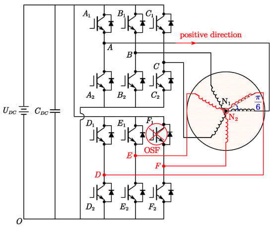
Figure 1.
Schematic of a typical DTPMSM drive.
DTPMSM is a high-order, nonlinear, and strongly coupled multivariable system. According to the vector space decoupling theory, the VSD model maps the variables of DTPMSM to three mutually orthogonal subspaces, namely, αβ subspace, xy subspace, and o1o2 subspace [8]. The transformation matrix Tαβ is as follows.
where f denotes the motor variables, including voltage, current, or flux. The fundamental component and (12k ± 1)th (k = 1, 2, 3, …) harmonic components are mapped to αβ subspace. Only the components in αβ subspace participate in the electromechanical energy conversion. The (6k ± 1)th (k = 1, 3, 5, …) harmonic components are mapped to xy subspace. The (6k ± 3)th (k = 1, 3, 5, …) harmonic components are mapped to the o1o2 subspace and negligible with the configuration of isolated neutral points [29].
By applying transformation (3), the variables in the αβ subspace are converted to the synchronous rotating dq frame. By applying transformation (4), the variables in the xy subspace are converted to a new frame, designated as dxqy frame. Then, the fifth and seventh current harmonic components can be transformed into the sixth harmonic components for elimination.
where θe is the electrical angle.
According to (1)–(4), the voltage and torque equations can be obtained as
where Rs is the stator resistance. Ld, Lq, and Lls are the d-axis inductance, q-axis inductance, and stator leakage inductance, respectively. ωe is the electrical angular velocity. Ψf is the rotor flux linkage. np is the number of pole pairs. ud, uq, udx, and uqy are the voltages of different subspaces.
3. Operation Analysis and Optimized FTC Strategy for Single OSF
3.1. Single OSF
A single OSF is a common fault in power devices. In this case, the switch is open while the freewheeling continues to operate normally. To clarify the impacts of OSFs on the inverter operation, the open-switch fault in the upper leg switch of phase F is taken as an example. In the VSD model, the normal operation of the remaining five phases will be affected by the single OSF. The schematic diagram is shown in Figure 1 when OSFs occur. Figure 2 illustrates two types of current paths when the polarity of the phase current changes under OSFs. It is evident that the current paths remain the same as in normal operation, flowing through the upper freewheeling diode and the lower IGBT when iF < 0. When iF > 0, there is only one path for the phase current, flowing through the lower freewheeling diode. Figure 3 depicts the phase current waveforms when OSFs occur during a positive current period. The phase current area that is approximately zero and negative is evenly divided. When the phase current is approximately equal to zero, OSFs are equivalent to OPFs, thereby affecting the normal SVPWM strategy of the DEF three-phase winding. Therefore, OSFs can be regarded as a combination of OPFs and normal operation.
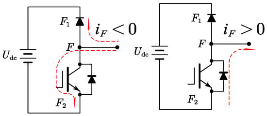
Figure 2.
Paths of phase current waveforms under OSFs.
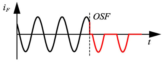
Figure 3.
The results of phase F current waveform when OSF of the upper switch occurs at iF > 0.
According to the Fourier series [30], the currents under OSFs can be represented as the superposition of multiple sinusoidal quantities. Since the higher-order harmonic components are relatively small, only the first four harmonic components are considered. Then, the αβ-axis currents and xy-axis currents can be expressed as
where m denotes the α, β, x, and y. imf is the fault currents of the m-axis. Im0 is the DC component of the m-axis current. φmn is the initial angle of the nth harmonic component of the m-axis current.
Substituting (7) into (3), the currents in the dq frame under OSFs can be expressed as
where idf and iqf are the fault currents of the dq-axis. Id0 and Iq0 are the DC components of the dq-axis current. φdn and φqn are the initial angles of the nth harmonic component of the dq-axis current.
The torque ripple at the quadruple frequency is small; hence, the fourth harmonic torque ripple can be ignored. Therefore, the torque under a single OSF can be simplified as a combination of DC, the second and third harmonic torque ripples, which can be calculated as
where Te0 is the DC component of torque. Te1, Te2, and Te3 are the fundamental, the second, and the third harmonic torque ripples, respectively.
It is evident that there are both odd-numbered and even-numbered harmonic torque ripples in the torque under OSFs. The reason is that the current under OSFs comprises two components: zero and negative currents. Consequently, the αβ-axis current contains DC components as well as even-numbered harmonic components, in addition to odd-numbered harmonic components. Clearly, the torque performance will deteriorate, and obvious torque ripples will occur under OSFs. It is essential to implement the FTC strategy under OSFs to improve its performance.
3.2. Proposed FTC Strategy for Single OSF
It is known that the copper loss and torque ripples can become excessive and cause damage to the motor when OSFs occur. Therefore, the objective of the FTC strategy for a single OSF in this paper is to reduce the torque ripples and copper loss. The copper loss of DTPMSM is calculated as
where Pcu_normal is the copper loss under normal operation. iα, iβ, ix, iy, io1, and io2 are the current of different subspaces.
Under OSF conditions, the operation can be viewed as a blend of normal and OPF operations. Specifically, when the current of phase F is negative, the copper loss is the same as (10). When the current of phase F is zero, constraints for the y-axis and β-axis fault currents can be derived from the inverse matrix of (2).
where iβf and iyf are the fault currents of the β-axis and y-axis, respectively.
From (6), to maintain constant output torque, the current references of the dq-axis under OPFs must align with those under normal operation, meaning the copper losses in the αβ subspace under the OPFs are identical to those under normal operation. Thus, the copper loss under a single OSF is then calculated as
where Pcu_OPF is the copper loss under OPF operation.
Thus, the copper loss under a single OSF is given by
where Pcu_OSF is the copper loss under OSF operation.
From (2), it is evident that the x-axis current is independent of phase F. Since the x-axis current gives no contribution to torque production, the current reference of the x-axis is set to zero to minimize the copper loss, as follows.
where Pcu_FTC is the copper loss under FTC operation.
Apparently, the conventional FTC strategy of DTPMSM under OSFs can also be categorized into two parts: normal operation and OPF-based FTC. The current reference of the x-axis is set to zero, while the current reference of the y-axis under OSFs is determined as
where iFf is the phase current of F under OSFs.
It is evident that the conventional FTC relies heavily on judging the magnitude of the fault current. However, the fault current cannot be exactly zero during OSFs, and it will be a value that is infinitely close to zero in practice. Therefore, (15) cannot set the threshold for judgement to exactly zero but rather to a value that is infinitely close to zero. Another challenge lies in setting an appropriate judgement threshold, which varies across different motors and operational conditions. Inappropriate threshold settings can lead to failure in entering FTC or engagement at incorrect times, both of which can impede performance improvement following a fault. While a virtual current with an accurate threshold has been proposed, it still cannot guarantee that the transition to FTC occurs at the optimal moment.
To enter FTC at the optimal moment and avoid misjudgment caused by sinusoidal current zero-crossing or sudden changes in load and speed, a novel FTC method based on actual current without relying on current judgement is proposed. Additionally, the y-axis current reference expression is derived using the Fourier series.
As shown in (16), the current reference of the y-axis is mainly composed of the DC component, the fundamental component, and the even harmonic component. The amplitude of each component is illustrated in Figure 4. From Figure 4 and (16), it can be observed that the amplitude of the DC component and the fundamental frequency component remain constant, while the amplitude of the even harmonic component decreases significantly as n increases. For simplicity of calculation and to avoid significant errors, n = 2 is selected. Subsequently, the current reference for the y-axis during the upper IGBT OSF of phase F can be determined as
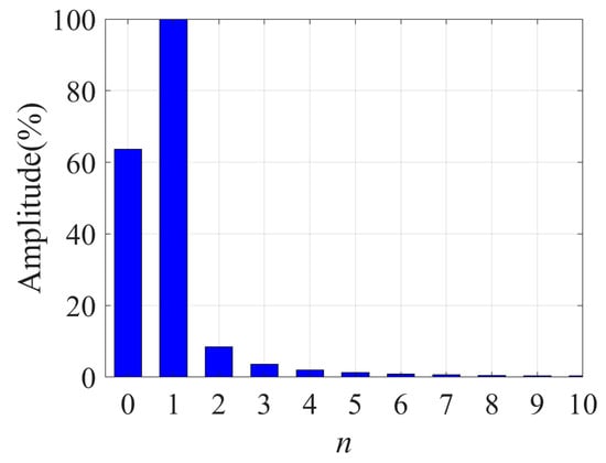
Figure 4.
Proportion of different components of y-axis current when n = 10.
Similarly, the current reference of the y-axis under the lower switch OSF of phase F is
Figure 5 illustrates the comparison of y-axis current references calculated by (15) and (17) when n = 2. It shows that the current reference calculated by (17) closely matches (15) in the positive half cycle. Although there are fluctuations in the zero-current region, they are relatively minor, making their impact on performance negligible.
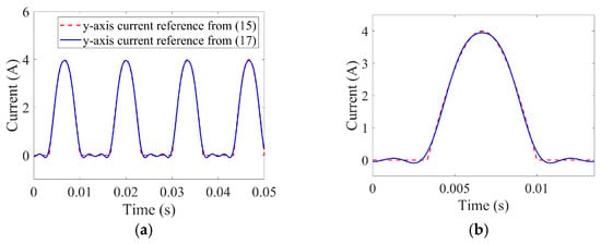
Figure 5.
Comparison of y-axis current reference calculated by (15) and (17). (a) Overall view. (b) Zoomed-in view of one cycle.
3.3. Proposed Control Scheme
For the xy-axis currents, the traditional control method involves current closed-loop control using two PI controllers, where the current references are set to zero, denoted as i*xy = 0. However, it can be derived from (5) that the harmonic impedance in the xy subspace is very small, consisting of only stator resistance and leakage inductance. This can result in a significant proportion of fifth and seventh harmonic currents even with low harmonic voltages. Therefore, closed-loop control using two proportional–integral quasi-resonant (PIR) controllers is implemented to suppress the fifth and seventh current harmonics. Considering that the phase margin of the PIR controller decreases with increasing speed, phase correction is adopted to improve stability. Firstly, the transfer function of the quasi-resonant controller with phase correction denoted as PCQPR, is expressed as
where Kpr and Kr are the proportional and resonant coefficients, respectively. ωc is the cut-off frequency. φ is the phase correction angle for the QPR controller. ωn is the resonant frequency, which varies with speed.
To avoid affecting the current regulation performance of the existing vector control system, the proportional gain of the PCQPR controller is set to zero. The transfer function of the PCPIR controller, as shown in Figure 5, is then given by
where Kp and Ki are the proportional and integral coefficients of the PI controller, respectively.
Besides, for inverters using an SVPWM modulation strategy, the time delay is considered as 1.5 Tsωe. To compensate for the time delay, the angle θe1 in Figure 5 is corrected by adding 1.5 Tsωe [31]. Then, the open-loop transfer function of the current loop in the xy subspace can be derived as
The introduced phase correction improves the system’s phase margin without affecting the gain at the resonance frequency. Therefore, the parameter design for the PCPIR controller follows the same design rules for the PIR controller. Since the method for designing PI controllers is well-established, only the parameter design of ωc and Kr for the resonant controller is provided as follows.
The cutoff frequency primarily influences the bandwidth of the controller. A smaller ωc enhances the frequency-selective characteristics of the controller, but AC drive systems are sensitive to current frequency fluctuations caused by load torque disturbances, compromising system stability. The bandwidth of the resonant controller can be calculated by
where fb is the bandwidth.
Based on the fluctuation range of the motor speed, the cutoff frequency ωc can be calculated. The resonant coefficient Kr primarily affects the gain at the resonant frequency. As Kr increases, the steady-state error is reduced, while the system’s phase margin decreases. Based on these design principles and experimental conditions, the parameters can be obtained.
It can be found from (5) that the voltage equations of the dx-axis and qy-axis are independent, with no coupling terms. The currents of the dx-axis and qy-axis are also independent of each other and orthogonal in the dx-qy coordinate system. Thus, the two PCPIR controllers can be designed and regulated independently. Additionally, since the parameters of the x-axis and y-axis are identical, the parameters for the two PCPIR controllers are the same. The parameters used for the PCPIR controllers in the experiment are presented in Table 1.

Table 1.
Parameters of the PCPIR controller.
According to (20), (21), and Table 1 and Table 2, the open-loop Bode diagram of the current loop with traditional PIR and proposed PCPIR is illustrated in Figure 6. It can be observed that the magnitudes of the current open loop with both controllers are nearly identical, but the phase margin is significantly improved with the proposed PCPIR. The phase margin is approximately 90°, indicating enhanced stability performance with the proposed PCPIR.

Table 2.
Motor parameters.
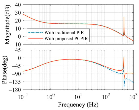
Figure 6.
The open-loop Bode diagram of the current loop with traditional PIR and proposed PCPIR.
Subsequently, the complete proposed control block diagram of DTPMSM for both normal operation and FTC is presented in Figure 7. In the xy subspace, the x-axis current is consistently set to zero under different operation modes to minimize losses. The flag ‘FLT’ switches the current references of the y-axis automatically according to the fault diagnosis results. The FLT values of 0 and 1 represent normal operation and FTC under OSFs, respectively. There is no current judgement, and this allows for accurate and stable entry into FTC. The entire proposed control scheme under faulty operation and FTC is the same as the normal operation instead of the y-axis current reference, enabling unified control, simple implementation, and seamless switching of current and torque between faulty operation and FTC.
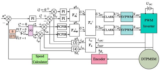
Figure 7.
The proposed control scheme for both normal operation and FTC.
4. Experimental Verification
To validate the effectiveness of the proposed method, a dual three-phase experimental platform has been constructed, as depicted in Figure 8. The DTPMSM is powered by two parallel three-phase two-level voltage inverters. PWM signals are generated by a control algorithm implemented on the DSP28335 processor from Texas Instruments, Dallas, TX, USA. The current loop execution frequency is configured to 10 kHz, matching the PWM frequency. The dead time is set to 500 ns. Two independent SVPWM modulation strategies are used to generate PWM signals. The three-phase asynchronous motor is controlled by the inverter to vary the load torque. The speed and torque sensor outputs pulse signals. Figure 9 presents waveforms of the gate drive and voltage between the collector and emitter of the IGBT under normal operation. The parameters of DTPMSM are detailed in Table 2.
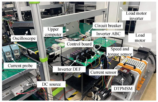
Figure 8.
DTPMSM experimental platform.
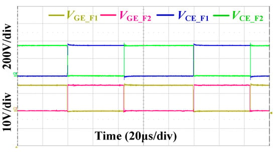
Figure 9.
Waveforms of gate drive and voltage between collector and emitter.
4.1. Normal Operation
Due to experimental constraints, the simultaneous measurement of all six phase currents is not feasible; hence, phase currents of both sets of three-phase windings are shown separately in Figure 10a,b. The current waveforms for both sets of windings under the same control strategy are nearly identical, indicating their symmetry. Figure 10c displays the waveforms of the dq-axis currents, xy-axis currents, and torque at 1500 r/min under rated load, obtained from the upper computer. As observed in Figure 10c, there are minimal fluctuations in the dq-axis currents, xy-axis currents, and torque, indicating effective suppression of the fifth and seventh harmonic components in phase currents by PCPIR controllers in the xy subspace. The motor exhibits good performance under rated operating conditions.
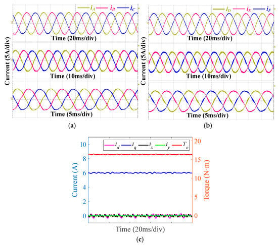
Figure 10.
Experimental results at different speeds (500 r/min, 1000 r/min, 1500 r/min) with rated load. (a) Phase currents of ABC. (b) Phase currents of DEF. (c) dq-axis currents, xy-axis currents, and torque under rated operating conditions.
4.2. Single OSF and FTC
To simulate OSFs, the drive signal of the phase F upper IGBT in the program is forced to the low level. By comparing (6), (9), (10), (13), and (14), it can be found that both torque ripple and copper loss increase significantly under a single OSF and FTC operations. Therefore, to protect the experimental platform, derated experiments are conducted under these operations. Specifically, the speed is set to 1000 r/min, and the load is limited to 7.5 N·m. Figure 11 presents experimental results under the upper IGBT OSF of phase F without FTC. In Figure 11a,b, phase current waveforms illustrate that during the conduction time of the upper IGBT, the fault current of phase F is forced to a value that is infinitely close to 0. In this condition, the y-axis current and β-axis currents exhibit the same amplitude with opposite phases. In αβ subspace, the amplitude of the α-axis current surpasses that of the β-axis current, resulting in noticeable second harmonic ripples in the dq-axis currents shown in Figure 11c,d. Conversely, during the conduction time of the lower IGBT, the fault current resembles normal operation, generating negative currents. Figure 11e and f present the torque waveforms and FFT results, illustrating that the upper IGBT OSF of phase F introduces the fundamental frequency torque ripple alongside the second and third harmonic torque ripples due to the absence of one switch.
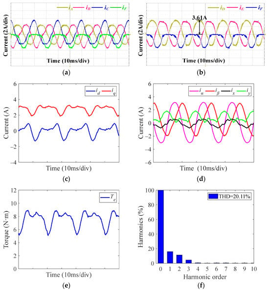
Figure 11.
Experimental results under upper IGBT OSF of phase F at 1000 r/min and 7.5 N·m without FTC. (a) Phase currents of ABCF. (b) Phase currents of DEF. (c) dq-axis currents. (d) αβ-axis and xy-axis currents. (e) Torque. (f) FFT results of torque.
Figure 12 and Figure 13 present the experimental results under the upper switch OSF of phase F with the traditional FTC strategy. The various current judgement thresholds are 0 A, −0.2 A, and −0.5 A, respectively. The fault-tolerant performance is evaluated by analyzing the changes in the phase current, different subspace current, and torque. Figure 12a and Figure 13a,b illustrate the experimental results when the judgement threshold is set to 0 A. A comparison with Figure 11 shows that the experimental results reveal a minimal difference between operation under the upper switch OSF without FTC and with the traditional FTC when the judgement threshold is 0 A. As a result, FTC cannot be effectively applied during the conduction period of the upper IGBT. Figure 12b and Figure 13c,d present the experimental results when the judgement threshold is −0.2 A. For this threshold, obvious oscillations are observed in the phase F current and the xy-axis current during the conduction period of the upper IGBT, even with the application of FTC. The reason is that the phase F current fluctuates around −0.2 A during the conduction time of the upper switch, leading to discontinuities in FTC operation. As a result, although the intermittent application of FTC reduces the torque ripple, the torque ripple remains significant. Figure 12c and Figure 13e,f show the experimental results when the judgement threshold is set to −0.5 A. Apparently, the motor operates under FTC. However, with a judgement threshold of −0.5 A, FTC unnecessarily engages during portions of the lower IGBT’s conduction time when the current is smaller than −0.5 A.
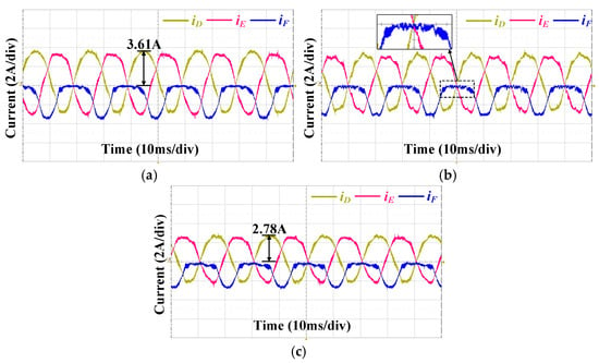
Figure 12.
Experimental current waveforms under upper IGBT OSF of phase at 1000 r/min and 7.5 N·m with traditional FTC strategy using various judgement thresholds. (a) Judgement threshold is 0 A. (b) Judgement threshold is −0.2 A. (c) Judgement threshold is −0.5 A.
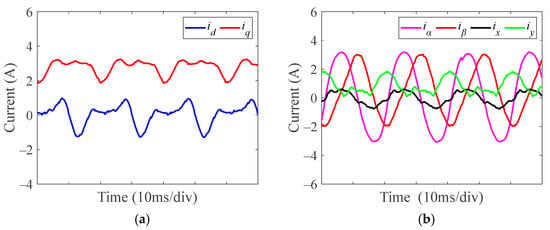
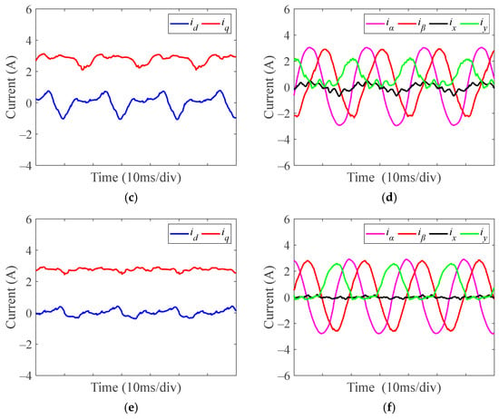
Figure 13.
Experimental current waveforms of dq-axis, αβ-axis, and xy-axis under upper IGBT OSF of phase F at 1000 r/min and 7.5 N·m with traditional FTC strategy using various judgement thresholds. (a,b) Judgement threshold is 0 A. (c,d) Judgement threshold is −0.2 A. (e,f) Judgement threshold is −0.5 A.
For a better understanding of the impact of different judgement thresholds on traditional FTC, the torque results under OSFs without FTC and torque with FTC under different judgement thresholds are compared in Figure 14. From Figure 14a, it can be seen that when the judgement threshold is 0 A, the torque with FTC is the same as the torque under OSFs without FTC. As seen in Figure 14b, the THD of torque decreases with lower judgement thresholds. It can be concluded that only lower judgement thresholds reduce torque ripples, highlighting the critical role of threshold selection in traditional FTC. The postfault performance of the conventional FTC significantly relies on threshold selection. Clearly, if the threshold selection is inappropriate, traditional current-based FTC cannot guarantee to enter FTC after a fault, nor can it ensure performance, thus lacking universality and robustness.
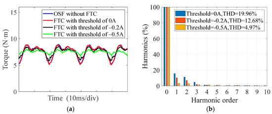
Figure 14.
Experimental torque results under upper IGBT OSF of phase at 1000 r/min and 7.5 N·m with traditional FTC using various judgement thresholds. (a) Torque waveforms. (b) FFT results of torque.
Figure 15 presents experimental results under the upper switch OSF of phase F with the proposed FTC strategy based on (17). In Figure 15d, it can be observed that the x-axis current is effectively controlled to be close to zero, thereby reducing copper losses. Figure 15c,e,f shows that the current harmonic components in the dq-axis currents are greatly reduced compared with Figure 11c, resulting in reduced torque ripples from 20.11% to 5.93%. Compared with Figure 14b, the torque ripple of the proposed method is much smaller than that of the traditional FTC at threshold values of 0 A and −0.2 A, but still slightly larger than that at a threshold value of −0.5 A. This is because the proposed method only approximates the first four harmonic components, resulting in relatively small errors. However, this avoids the selection of the current judgement threshold and ensures the robustness of fault tolerance. This performance improvement with the proposed FTC is evident when compared with Figure 11 and Figure 14, highlighting its effectiveness.
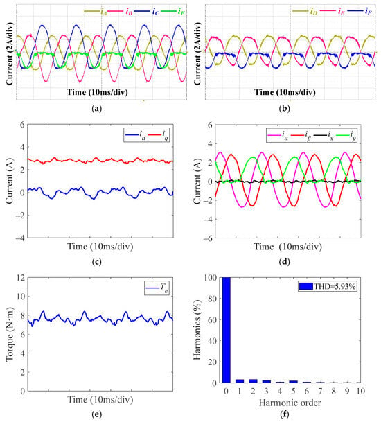
Figure 15.
Experimental results under upper IGBT OSF of phase F at 1000 r/min and 7.5 N·m with proposed FTC. (a) Phase currents of ABCF. (b) Phase currents of DEF. (c) dq-axis currents. (d) αβ-axis and xy-axis currents. (e) Torque. (f) FFT results of torque.
4.3. Dynamic Performance
Dynamic performance experimental verification is also essential alongside steady-state experimental verification. Figure 16 illustrates the dynamic performance of the DTPMSM transitioning from OSFs to traditional FTC using various current judgement thresholds, including phase currents and torque. It can be observed that no torque spikes occur when transitioning from OSFs to FTC operation. This is due to the continuity of the current from the negative half-cycle (normal operation) to the approximately zero half-cycle (traditional FTC). However, the torque performance of FTC varies depending on the selected current judgement threshold. Figure 17 depicts the experimental results during transitions from normal operation to OSFs and then to FTC. OSFs occur during the conduction time of the upper switch, so the phase F current is forced to be a value close to zero immediately, and this condition is similar to the OPF of phase F. At this moment, the torque decreases, as shown in Figure 17c. Then, the motor operates in the conduction time of the lower switch. During lower switch conduction, the operation is similar to normal operation, restoring torque to its reference level. From the next electrical period, the torque ripple starts to increase, and there is no sudden change in torque with the change operation mode, ensuring smooth torque transitions. Compared with Figure 16, the proposed method eliminates the need for a current judgement threshold, ensuring that the performance is not affected by threshold selection. This proposed approach guarantees a smooth and stable transition into FTC after an OSF fault.
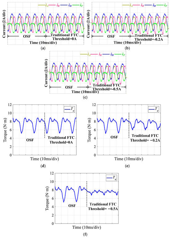
Figure 16.
Dynamic performances of DTPMSM transitioning from OSF to traditional FTC using various judgement thresholds. (a) Phase currents with a judgement threshold of 0 A. (b) Phase currents with a judgement threshold of −0.2 A. (c) Phase currents with a judgement threshold of −0.5 A. (d) Torque with a judgement threshold of 0 A. (e) Torque with a judgement threshold of −0.2 A. (f) Torque with a judgement threshold of −0.5 A.
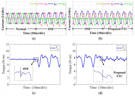
Figure 17.
Dynamic performances of the proposed method with the change in operation mode under OSFs. (a) Phase currents from normal operation to OSFs. (b) Phase currents from OSF to FTC. (c) Torque from normal operation to OSFs. (d) Torque from OSF to FTC.
Further dynamic performances of the proposed method under OSFs with varying rotational speed and load torque are given in Figure 18. First, the rotational speed is step-changed from 100 to 1500 r/min and from 1500 to 100 r/min. The load torque is 7.5 N·m. The experimental results under OSFs are shown in Figure 18a. It can be seen that, with the change in rotational speed, the motor can still operate stably without overshoot and oscillation. In Figure 18b, the load torque is changed manually from 3.5 to 15 N·m and from 15 to 3.5 N·m, so the load change time is different. This will not affect the validation of the results. The rotational speed is 1000 r/min. Figure 18b illustrates that the motor can still operate stably without overshoot and oscillation. These results confirm that the proposed strategy achieves robust dynamic performance across different operational conditions.
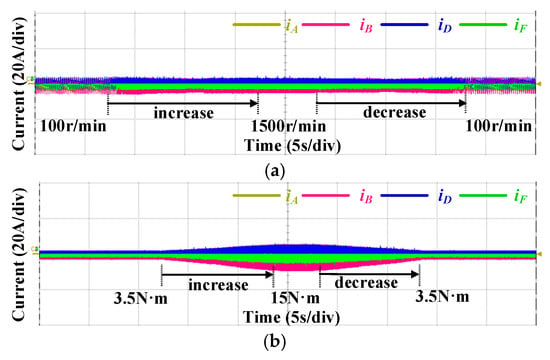
Figure 18.
Dynamic performances of the proposed method under OSFs. (a) Rotor speed step-changing. (b) Load torque changing.
5. Conclusions
This article proposed an optimized FTC strategy for a single OSF of DTPMSM drives. The operations under OSFs are analyzed, and the reason for increased torque ripples are investigated. The results show that the torque ripples are inevitable due to the absence of one switch in the bridge arm. Based on the theoretical analysis, the FTC method is proposed for DTPMSM under OSFs with the same output torque. The transformation matrix and control scheme of the proposed FTC is the same as that in normal operation; thus, it has unified control and simple implementation. Smooth transitions of current and torque can be realized between faulty operation and FTC. Compared with traditional FTC methods, the proposed strategy demonstrates superior performance and robust application without the requirement for current judgement. Theoretical analysis and steady-state experiments show a significant reduction in torque ripples under OSFs with the proposed FTC strategy. Dynamic experiments further validate the proposed strategy, highlighting its ability to achieve stable performance under different operations.
Author Contributions
Conceptualization, L.C. and M.C.; methodology, L.C.; software, B.L.; validation, L.C., B.L., X.S. and F.J.; formal analysis, L.C.; investigation, L.C. and F.J.; resources, M.C.; data curation, B.L. and X.S.; writing—original draft preparation, L.C.; writing—review and editing, M.C.; visualization, X.S. and F.J.; supervision, M.C.; project administration, M.C.; funding acquisition, M.C. All authors have read and agreed to the published version of the manuscript.
Funding
This work was funded in part by the National Key Research and Development Program of China under grant no. 2021YFB3602303.
Data Availability Statement
The data are contained within the article.
Acknowledgments
The authors would like to thank PLEXIM Inc. for the support of the powerful simulation tools PLECS with version 4.5.8 and also Leadrive Inc. for the support of the hardware platform.
Conflicts of Interest
The authors declare no conflicts of interest.
References
- Levi, E. Multiphase electric machines for variable-speed applications. IEEE Trans. Ind. Electron. 2008, 55, 1893–1909. [Google Scholar] [CrossRef]
- Levi, E.; Barrero, F.; Duran, M.J. Multiphase machines and drives—Revisited. IEEE Trans. Ind. Electron. 2016, 63, 429–432. [Google Scholar] [CrossRef]
- Barrero, F.; Duran, M.J. Recent advances in the design, modeling, and control of multiphase machines—Part I. IEEE Trans. Ind. Electron. 2016, 63, 449–458. [Google Scholar] [CrossRef]
- Duran, M.J.; Barrero, F. Recent advances in the design, modeling, and control of multiphase machines—Part II. IEEE Trans. Ind. Electron. 2016, 63, 459–468. [Google Scholar] [CrossRef]
- Mwasilu, F.; Jung, J.W. Enhanced fault-tolerant control of interior PMSMs based on an adaptive EKF for EV traction applications. IEEE Trans. Power Electron. 2016, 31, 5746–5758. [Google Scholar] [CrossRef]
- Gao, H.; Zhang, Z.; Liu, Y.; Huang, W.; Xue, H. Development and analysis of dual three-phase PMSM with phase-shifted hybrid winding for aircraft electric propulsion application. IEEE Trans. Transp. Electrif. 2023, 10, 6497–6508. [Google Scholar] [CrossRef]
- Zhou, C.; Yang, G.; Su, J. PWM strategy with minimum harmonic distortion for dual three-phase permanent-magnet synchronous motor drives operating in the overmodulation region. IEEE Trans. Power Electron. 2016, 31, 1367–1380. [Google Scholar] [CrossRef]
- Zhao, Y.F.; Lipo, T.A. Space vector PWM control of dual three-phase induction machine using vector space decomposition. IEEE Trans. Ind. Appl. 1995, 31, 1100–1109. [Google Scholar] [CrossRef]
- Che, H.S.; Duran, M.J.; Levi, E.; Jones, M.; Hew, W.-P.; Rahim, N.A. Postfault operation of an asymmetrical six-phase induction machine with single and two isolated neutral points. IEEE Trans. Power Electron. 2014, 29, 5406–5416. [Google Scholar] [CrossRef]
- Baudart, F.; Dehez, B.; Matagne, E.; Telteu-Nedelcu, D.; Alexandre, P.; Labrique, F. Torque control strategy of polyphase permanent-magnet synchronous machines with minimal controller reconfiguration under open-circuit fault of one phase. IEEE Trans. Ind. Electron. 2012, 59, 2632–2644. [Google Scholar] [CrossRef]
- Liang, G.; Huang, S.; Liao, W.; Zhang, Z.Z.; Liu, Y.; Feng, C.Q.; Wu, X.; Huang, S.D. An optimized modulation of torque and current harmonics suppression for dual three-phase PMSM. IEEE Trans. Transp. Electrif. 2024, 10, 3443–3454. [Google Scholar] [CrossRef]
- Guzman, H.; Barrero, F.; Duran, M.J. IGBT-gating failure effect on a fault-tolerant predictive current-controlled five-phase induction motor drive. IEEE Trans. Ind. Electron. 2015, 62, 15–20. [Google Scholar] [CrossRef]
- Hu, Y.; Feng, Y.; Li, X. Fault-tolerant hybrid current control of dual three-phase PMSM with one phase open. IEEE J. Emerg. Sel. Top. Power Electron. 2022, 10, 3418–3426. [Google Scholar] [CrossRef]
- Dwari, S.; Parsa, L. An optimal control technique for multiphase PM machines under open-circuit faults. IEEE Trans. Ind. Electron. 2008, 55, 1988–1995. [Google Scholar] [CrossRef]
- Barcaro, M.; Bianchi, N.; Magnussen, F. Faulty operations of a PM fractional-slot machine with a dual three-phase winding. IEEE Trans. Ind. Electron. 2011, 58, 3825–3832. [Google Scholar] [CrossRef]
- Nguyen, N.K.; Meinguet, F.; Semail, E.; Kestelyn, X. Fault-tolerant operation of an open-end winding five-phase PMSM drive with short-circuit inverter fault. IEEE Trans. Ind. Electron. 2016, 63, 595–605. [Google Scholar] [CrossRef]
- Liu, L.; Wang, K.; Guo, L.L.; Li, J. Analysis of inter-turn short circuit faults in dual three-phase PMSM for electromechanical actuator. IEEE Trans. Transp. Electrif. 2023, 9, 4059–4070. [Google Scholar] [CrossRef]
- Wang, X.Q.; Wang, Z.; Gu, M.; Xiao, D.; He, J.; Emadi, A. Diagnosis-free self-healing scheme for open-circuit faults in dual three-phase PMSM drives. IEEE Trans. Power Electron. 2020, 35, 12053–12071. [Google Scholar] [CrossRef]
- Tousizadeh, M.; Che, H.S.; Selvaraj, J.; Rahim, N.A.; Ooi, B. Performance comparison of fault-tolerant three-phase induction motor drives considering current and voltage limits. IEEE Trans. Ind. Electron. 2019, 66, 2639–2648. [Google Scholar] [CrossRef]
- Hu, K.; Liu, Z.; Tasiu, I.A.; Chen, T. Fault diagnosis and tolerance with low torque ripple for open-switch fault of IM drives. IEEE Trans. Transp. Electrif. 2021, 7, 133–146. [Google Scholar] [CrossRef]
- Cecati, C.; Di Tommaso, A.O.; Genduso, F.; Miceli, R.; Ricco Galluzzo, G. Comprehensive modeling and experimental testing of fault detection and management of a nonredundant fault-tolerant VSI. IEEE Trans. Ind. Electron. 2015, 62, 3945–3954. [Google Scholar]
- Tian, B.; Molinas, M.; An, Q.; Zhou, B.; Wei, J. Freewheeling current-based sensorless field-oriented control of five-phase permanent magnet synchronous motors under insulated gate bipolar transistor failures of a single phase. IEEE Trans. Ind. Electron. 2022, 69, 213–224. [Google Scholar] [CrossRef]
- Sun, J.; Zheng, Z.; Li, C.; Wang, K.; Li, Y. Optimal fault-tolerant control of multiphase drives under open-phase/open-switch faults based on DC current injection. IEEE Trans. Power Electron. 2022, 37, 5928–5936. [Google Scholar] [CrossRef]
- Yang, G.; Hussain, H.; Li, S.; Zhang, X.; Yang, J.Q.; Lee, C.H.T. Design and analysis of universal natural fault-tolerant SVPWM strategy with simplified fault diagnosis for multiphase motor drives. IEEE J. Emerg. Sel. Top. Power Electron. 2023, 11, 4340–4354. [Google Scholar] [CrossRef]
- Yu, K.; Wang, Z.; Gu, M.; Wang, X.Q. Universal control scheme of dual three-phase PMSM drives with single open-phase fault. IEEE Trans. Power Electron. 2022, 37, 14034–14039. [Google Scholar] [CrossRef]
- Song, Z.; Jia, Y.; Liu, C. Open-phase fault-tolerant control strategy for dual three-phase permanent magnet synchronous machines without controller reconfiguration and fault detection. IEEE Trans. Power Electron. 2023, 38, 789–802. [Google Scholar] [CrossRef]
- Wang, X.Q.; Wang, Z.; He, M.; Zhou, Q.; Liu, X.; Meng, X. Fault-tolerant control of dual three-phase PMSM drives with minimized copper loss. IEEE Trans. Power Electron. 2021, 36, 12938–12953. [Google Scholar] [CrossRef]
- Xu, L.; Ren, H.; Jiang, T.; Liu, G.; Zhao, W.X. Minimum copper loss fault-tolerant control of zero phase shift dual three-phase SPMSM by using reduced-order transformation matrices. IEEE Trans. Energy Convers. 2024, 1–10. [Google Scholar] [CrossRef]
- Hu, Y.; Zhu, Z.Q.; Liu, K. Current control for dual three-phase permanent magnet synchronous motors accounting for current unbalance and harmonics. IEEE J. Emerg. Sel. Top. Power Electron. 2014, 2, 272–284. [Google Scholar]
- Campos-Delgado, D.U.; Pecina-Sanchez, J.A.; Espinoza-Trejo, D.R. Diagnosis of open-switch faults in variable speed drives by stator current analysis and pattern recognition. IET Electr. Power Appl. 2013, 7, 509–522. [Google Scholar] [CrossRef]
- Bae, B.H.; Sul, S.K. A compensation method for time delay of full-digital synchronous frame current regulator of PWM AC drives. IEEE Trans. Ind. Appl. 2003, 39, 802–810. [Google Scholar] [CrossRef]
Disclaimer/Publisher’s Note: The statements, opinions and data contained in all publications are solely those of the individual author(s) and contributor(s) and not of MDPI and/or the editor(s). MDPI and/or the editor(s) disclaim responsibility for any injury to people or property resulting from any ideas, methods, instructions or products referred to in the content. |
© 2024 by the authors. Licensee MDPI, Basel, Switzerland. This article is an open access article distributed under the terms and conditions of the Creative Commons Attribution (CC BY) license (https://creativecommons.org/licenses/by/4.0/).