Review

Key Issues of Salt Cavern Flow Battery

by
Si Huang
1,2,
Yinping Li
1,2,
Xilin Shi
1,2,*,
Yahua Liu
3,
Hongling Ma
1,2,
Peng Li
1,2,
Yuanxi Liu
1,2,
Xin Liu
4,
Mingnan Xu
1,2 and
Chunhe Yang
1,2
1
State Key Laboratory of Geomechanics and Geotechnical Engineering, Institute of Rock and Soil Mechanics, Chinese Academy of Sciences, Wuhan 430071, China
2
University of Chinese Academy of Sciences, Beijing 100049, China
3
School of Chemistry and Chemical Engineering, Hefei University of Technology, Hefei 230009, China
4
Institut für Geotechnik, Universität für Bodenkultur, Feistmantelstraße 4, 1180 Vienna, Austria
*
Author to whom correspondence should be addressed.
Energies 2024, 17(20), 5190; https://doi.org/10.3390/en17205190
Submission received: 23 September 2024 / Revised: 5 October 2024 / Accepted: 17 October 2024 / Published: 18 October 2024
(This article belongs to the Special Issue Electrochemical Conversion and Energy Storage System)

Abstract

:
Salt cavern flow batteries (SCFBs) are an energy storage technology that utilize salt caverns to store electrolytes of flow batteries with a saturated NaCl solution as the supporting electrolyte. However, the geological characteristics of salt caverns differ significantly from above-ground storage tanks, leading to complex issues in storing electrolytes within salt caverns. Therefore, investigating and summarizing these issues is crucial for the advancement of SCFB technology. This paper’s innovation lies in its comprehensive review of the current state and development trends in SCFBs both domestically and internationally. First, the current development status of SCFB energy storage technology both domestically and internationally is summarized. Then, eight main issues are proposed from the perspectives of salt cavern geological characteristics (tightness, conductivity, ions, and temperature) and electrolyte properties (selection, permeability, corrosion, and concentration). Finally, a novel SCFB system is proposed to address the most critical issue, which is the low concentration and uneven distribution of active materials in the current SCFB system. The review in this paper not only comprehensively summarizes the development status of SCFBs both domestically and internationally, but also points out the direction for the future research focussing on SCFBs.

1. Introduction

Energy security constitutes the prerequisite and foundation for the clean and low-carbon transformation of energy. At the 21st United Nations Climate Change Conference, 178 countries signed the Paris Climate Change Agreement [1,2]. This accord establishes a long-term goal to guide nations in significantly reducing global greenhouse gas emissions, aiming to limit the increase in global average temperature to within 2 degrees Celsius above pre-industrial levels, with efforts to constrain the increase to 1.5 degrees Celsius [3,4]. Achieving this objective requires global cooperation among nations on peak carbon emissions, carbon neutrality, and net-zero emissions, which has garnered broad international consensus [5,6].
As the largest developing country and the largest emitter of carbon dioxide [7,8], China announced, in September 2020, its intention to peak carbon dioxide emissions by 2030 and achieve carbon neutrality by 2060 [9,10]. Despite a recent decline in coal consumption, coal still accounted for 56% of China’s total energy consumption in 2021 [11]. Concurrently, oil and natural gas each accounted for 27.4%, indicating that fossil fuels continue to dominate China’s energy consumption landscape [12,13]. From this perspective, balancing energy security and supply capacity while meeting low-carbon requirements and achieving sustainable development presents a significant challenge for China’s energy system [14].
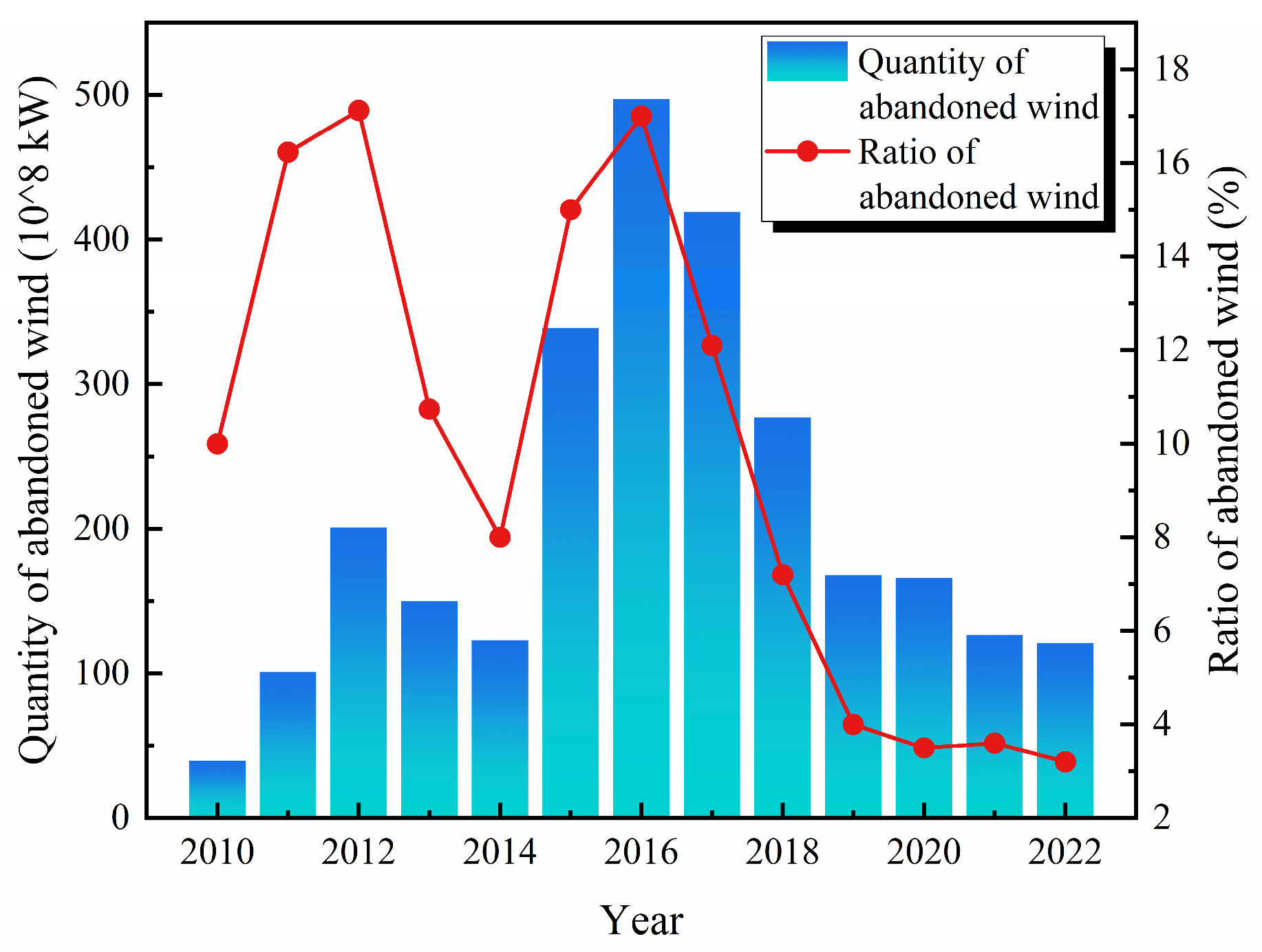
The development of renewable energy sources, such as wind and solar energy, to replace fossil energy sources is an effective measure for China to realize energy conservation [15] and emission reduction and a low-carbon transformation of its energy structure [16]. In recent years, China’s solar and wind energy has been developing rapidly, showing a growing trend year after year (Figure 1). In 2001, China’s total installed capacity of wind power ranked first in the world. On the other hand, China’s PV manufacturing output has accounted for more than 2/3 of the world’s total in 2021, and its cumulative installed capacity has ranked first in the world for seven consecutive years. Although the development of renewable energy represented by wind and solar energy is relatively mature in China, it still faces some problems in the process of practical application. For example, the power generation from wind energy resources during peak hours exceeds the carrying capacity of the operating power grid, leading to the shutdown of power generation facilities [17], resulting in a serious waste of resources and economic losses, as shown in Figure 2 [18]. According to statistics, in 2016 alone, the total amount of wind abandoned nationwide was as high as 49.7 GWh. China’s solar industry is also facing this problem. Not only China, but also many countries in the world have encountered grid connection problems when developing renewable energy [19,20,21,22]. In addition, the volatility and intermittency of renewable energy requires large-scale energy storage technologies to cope with it [23].
Currently, there are many kinds of energy storage technologies in China, mainly including pumped storage, compressed air energy storage, flow batteries, superconducting energy storage, flywheel energy storage, and so on [26]. Among these, flow batteries have received a great deal of attention [27]. The reason is that the design of flow batteries allows for the independent customization of their power and capacity [28]. The output power is determined by the number and size of the battery modules, while the energy storage capacity depends on the volume and concentration of the electrolytes [29]. In addition, the amount of stored energy is directly related to the size of flow batteries. Recycling positive and negative electrolytes is feasible without environmental risk [30]. Therefore, flow batteries offer numerous advantages such as a long cycle life, high safety, and scalability, positioning them as one of the most promising energy storage technologies [31].
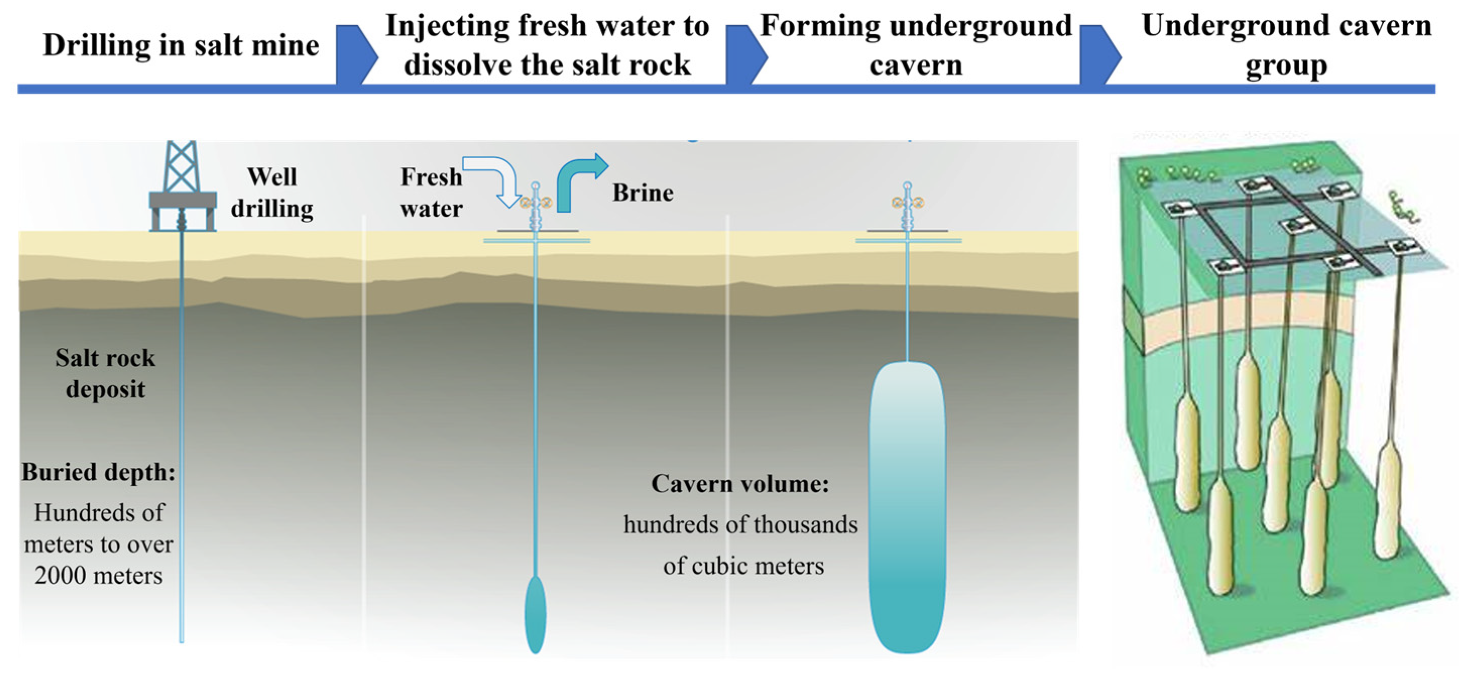
To date, existing flow battery systems typically rely on aboveground tanks [32]. However, this method is considered costly and space intensive. The 100 MW Dalian flow battery energy storage and peak shaving power plant in China serves as a typical example. The facility comprises 716 large tanks and 358 containers, occupying approximately 14,000 square meters, further highlighting the limitations of aboveground storage. Moreover, maintaining a constant temperature for the electrolyte requires air conditioning, consuming additional electricity and reducing overall efficiency [33]. Furthermore, such installations are susceptible to attack during wartime, posing significant threats to energy security. To address these issues, underground salt cavern storage presents a promising solution [34]. A salt cavern is a cavity formed in a salt mine by means of water-soluble mining [35], with a burial depth ranging from a few hundred meters to more than 2000 m [36], and its construction process is shown in Figure 3. Salt rock is internationally recognized as the most favorable choice for underground storage due to its extremely low porosity [37], extremely low permeability [38], stable mechanical properties [39], self-healing through salt recrystallization [40], and ability to adapt to underground storage pressures and medium changes [41]. Additionally, individual salt caverns can have capacities of up to millions of cubic meters, comparable to the volume of a skyscraper [42]. Such immense storage capacity aligns perfectly with the high capacity demands of flow batteries, potentially saving significant costs on land and storage equipment [29]. Considering that salt caverns are constructed within underground salt formations filled with a NaCl solution, using electrolytes supported by the NaCl solution for storage in salt caverns is suitable. This approach not only prevents continued dissolution of surrounding salt cavern rock, but also allows for the in situ utilization of the NaCl solution within the cavern. Furthermore, in the field of flow batteries, it is believed that using the NaCl solution as a supporting electrolyte offers advantages such as low cost and environmental friendliness, making it more competitive in the long-term energy storage market [43].
Research on salt cavern flow batteries (SCFBs) abroad has progressed to the extent of on-site engineering and construction [44]. The German energy company Ewe Gasspeicher GmbH, in conjunction with the Friedrich Schiller University of Jena, has taken the lead in opening an SCFB project called Brine4Power worldwide (Figure 4). The project uses a saltwater electrolyte with recyclable polymers as active molecules. Those materials are far more environmentally friendly than the heavy metal/sulfuric acid mix that other redox flow electrolytes are often made of. The SCFB system is being built in the Jemgum gas storage facility, utilizing two huge underground salt caverns with a volume of 100,000 m3 per cavern. The project can have a battery capacity of up to 700 MWh and an output of up to 120 MW, which is enough output to power 75,000 homes for a day [44]. The energy company claims to expect that Ewe Gasspeicher GmbH will have a fully operational SCFB system in the near future, which may fundamentally change the storage market by controlling the energy market. This means that Ewe Gasspeicher GmbH will be making the world’s largest battery. Unlike other storage facilities that convert current into other energy carriers, Ewe Gasspeicher GmbH stores electricity directly in Brine4Power.
However, research on SCFBs in China is still in the beginning stage, with very limited literature available in this field [46]. Existing studies are mainly from the aspects of salt cavern geology and electrolyte design [47]. From the aspect of salt cavern geology, Ding et al. [45] integrated wind and solar energy, proposing an SCFB system based on an all-vanadium flow battery across two salt caverns, as shown in Figure 4b. And a 220 MW/1100 MWh two-cavity SCFB system was proposed using the example of Jintan Salt Mine, and its stability was analyzed over a period of 20 years. The results show that the maximum settlement of the top plate is 0.113 m, the maximum deformation of the waist is 0.224 m, and the volume loss rate is <1.78%, demonstrating favorable long-term stability. In addition, the technical and economic benefits of the system were also analyzed in a more comprehensive way, resulting in a single-cycle net present value (NPV) of investment of CNY 1.539 billion, an annual net profit of CNY 280 million, and a dynamic payback period of 8 years. Therefore, the SCFB system is promising for the future, both from the perspective of long-term stability and economic returns [48,49]. From the aspect of electrolyte design improvement, to address the problems of the limited solubility and electrochemical stability of active organic materials in saturated saline solution, Wang et al. [50] synthesized an unsymmetrical two-electron 3-(1′-(2-hydroxyethyl)-[4,4′-bipyridin]-1,1′-diium-1-yl)propane-1-sulfonate bromide ((SO3)V(OH)Br). After pairing with (2,2,6,6-tetramethylpiperidin-1-yl) oxyl (TEMPO) derivatives, this battery achieved a theoretical capacity of 24.1 Ah/L and theoretical energy density of 19.6 Wh/L, which provides an unusually high cell voltage of 1.63 V, an energy efficiency of about 78%, and an average capacity retention of 99% per cycle at 30 mA/cm2. It can be seen that the battery exhibits high cell efficiency and stable cycling performance, providing a promising strategy for the development of large-scale SCFB [51]. In addition, Wang et al. [52] also attempted to explore SCFBs using a low-cost iron/organic oxide reduction material system with the addition of the ligand threonine to enhance the stability of iron ions in aqueous solution. Pairing with a two-electron violet-refined cathode electrolyte and saturated saline solution as the supporting electrolyte provided 99% coulombic efficiency and 80% energy efficiency with an average capacity retention of 99.5% per cycle.
However, unlike the German Jemgum SCFB reservoir, which was constructed in a giant thick salt mound (the thickness of which can reach hundreds to thousands of meters) deposited in the sea, the basic features of salt rocks in China are the number of salt rock layers [53], the thinness of a single layer, and the large number of insoluble or insoluble interlayers [54], which is a typical thin interlayer salt rock structure [55]. Therefore, the effect of salt cavern geological characteristics on SCFBs must be considered when constructing SCFB systems. In this study, the key issues of constructing an SCFB from the perspective of the interaction between the salt caverns and electrolytes is analyzed (Figure 5). And based on the key issues, a novel SCFB system is proposed to provide a practical new solution for building an SCFB system.

2. Key Issues on Salt Caverns

2.1. Tightness of Salt Cavern

Good tightness of salt caverns is a prerequisite for the safe operation of salt cavern storages. It is equally important for SCFBs. The occurrence of redox reactions in flow batteries is highly contingent upon a gas environment that is inert because of the risk of air components like oxygen compromising the electrochemical properties of active materials [18]. Therefore, it is necessary for underground salt caverns to possess excellent tightness, as this allows for the complete replacement of air within the cavern with inert gas, thereby facilitating a suitable gas environment that can sustain stable redox reactions in the SCFB [56]. The addition of an isolation medium facilitates the flow of electrolytes in the salt cavern in a certain direction.
In terms of economics, nitrogen is the recommended choice for the isolation medium [57], compared to oil, which has high viscosity and is susceptible to electrolyte mixture during the charge and discharge processes, thereby impacting the SCFB’s electrochemical performance. Furthermore, nitrogen meets the electrochemical requirements for the redox reactions of active materials, thereby making it an ideal and comprehensive choice for the selection of both inert gas and the isolation medium. However, the disadvantage of nitrogen as an isolation medium is the high cost of production and extraction. In addition, nitrogen may lead to human asphyxiation accidents when it accumulates in large quantities in confined spaces, and, therefore, safety measures need to be ensured during its use. In contrast, inert gasses such as helium and argon can also be selected as isolation media. When the isolation medium is selected as nitrogen, the nitrogen requirement for the tightness of salt caverns is not as high as natural gas, which allows for a small amount of leakage to occur [58]. In the event of gas leakage leading to inadequate gas pressure, it can be solved by replenishing the gas with nitrogen, which is a simple and easy process to implement.

2.2. Conductivity of Interlayers

The surrounding rocks of salt caverns are the rocks around the ore body and around the rock mass, including salt rocks, interlayers, and other relevant formations. The conductivity of interlayers connecting adjacent salt caverns during the charge and discharge processes of the SCFB has become a matter of special attention [59]. The potential occurrence of conductive phenomena between adjacent salt caverns may have detrimental effects on the stability of the underground space and may also decrease the energy output of the SCFB. It is noteworthy that mudstones and loose sandstones possess high electrical conductivity and low resistivity [60]. When mudstone and loose sandstone contain a certain amount of groundwater, several types of salts are dissolved in the groundwater, leading to a large number of ions in the groundwater. At this time, the groundwater can be considered to be free electrolytes with good conductivity, making the conductivity of mudstone and loose sandstone improved as well [61]. Therefore, preliminary geological exploration work for salt cavern sites should aim to identify any interlayer with conductive properties that may be connected to an adjacent salt cavern. If such a stratum is discovered, it is unsuitable for constructing a salt cavern.

2.3. Ions in Salt Caverns

The foreign salt caverns are constructed within extensive salt domes, whereas those in China primarily stem from thin-layered formations leading from lacustrine sedimentation, displaying the distinct feature of multiple interlayers [62]. These interlayers are primarily composed of calcareous mudstone, calcareous mannitite, clinopyroxene, oil shale, and sandstone. However, the presence of interlayers introduces certain levels of impurity ions [63], namely K+, Ca2+, Mg2+, CO32−, SO42−, Fe2+, Al3+, Mo4+, Sr2+, and Si4+, within the underground salt caverns, as illustrated in Figure 6.
Existing electrolyte studies utilizing NaCl as the supporting electrolyte have been carried out using pure brine and have not considered the effect of the above impurity ions on the overall performance of the flow battery using NaCl as the supporting electrolyte [64,65,66]. The presence of these impurity ions is inevitable in the salt caverns. These impurity ions may have adverse chemical reactions with the positive or negative active materials. It is necessary to design targeted chemical experiments in the laboratory to evaluate the adverse effects of these impurity ions. Moreover, what is more important is how to reduce or eliminate the impact of these impurity ions on the SCFB system. It might be possible to set up a chemical reaction pool before the positive or negative active materials reach the electrodes, with the aim of minimizing the content of impurity ions by precipitating and settling them down through chemical reactions. However, the content of K+ cannot be reduced in this method. Therefore, the effect of the presence of K+ on the SCFB system should be given special attention.

2.4. Temperature in Salt Caverns

Salt caverns located at varying underground depths, ranging from tens to thousands of meters, exhibit a corresponding increase in underground temperature as depth increases [67]. Investigations have demonstrated that temperatures at 1000 m underground can reach 50 °C, while temperatures at 2000 m can reach 70 °C [68]. Such high temperatures in the cavern can adversely impact the active materials present in the positive and negative electrolytes, leading to their instability and decomposition [18], ultimately leading in a deterioration of the electrochemical performance of the SCFB.
However, existing research predominantly focuses on electrolytes employing NaCl as the supporting electrolyte at room temperature, with limited attention given to the effects of higher temperatures. Consequently, it is imperative to conduct experimental studies that evaluate the degree to which various geothermal gradients influence these electrolytes and their overall electrochemical performance in SCFBs. Suqian Time Energy Storage Technology Co. has developed an aqueous organic flow battery that operates at an ambient temperatures from −40 °C to 60 °C, so the salt caverns should be constructed at a depth of no more than 1500 m. Given the inevitable influence of geothermal gradients, research efforts should also be aimed to enhance the high temperature resistance of these electrolytes so that they can maintain optimal electrochemical performance under higher geothermal gradient conditions.

3. Key Issues on Electrolytes

3.1. Selection of Electrolytes

The electrolytes are a crucial component in the operation of the SCFB system, as it substantially influences the electrochemical performance. An investigation of the available literature revealed that minimal research has been conducted on electrolytes with NaCl as the supporting electrolyte, as illustrated in Table 1.
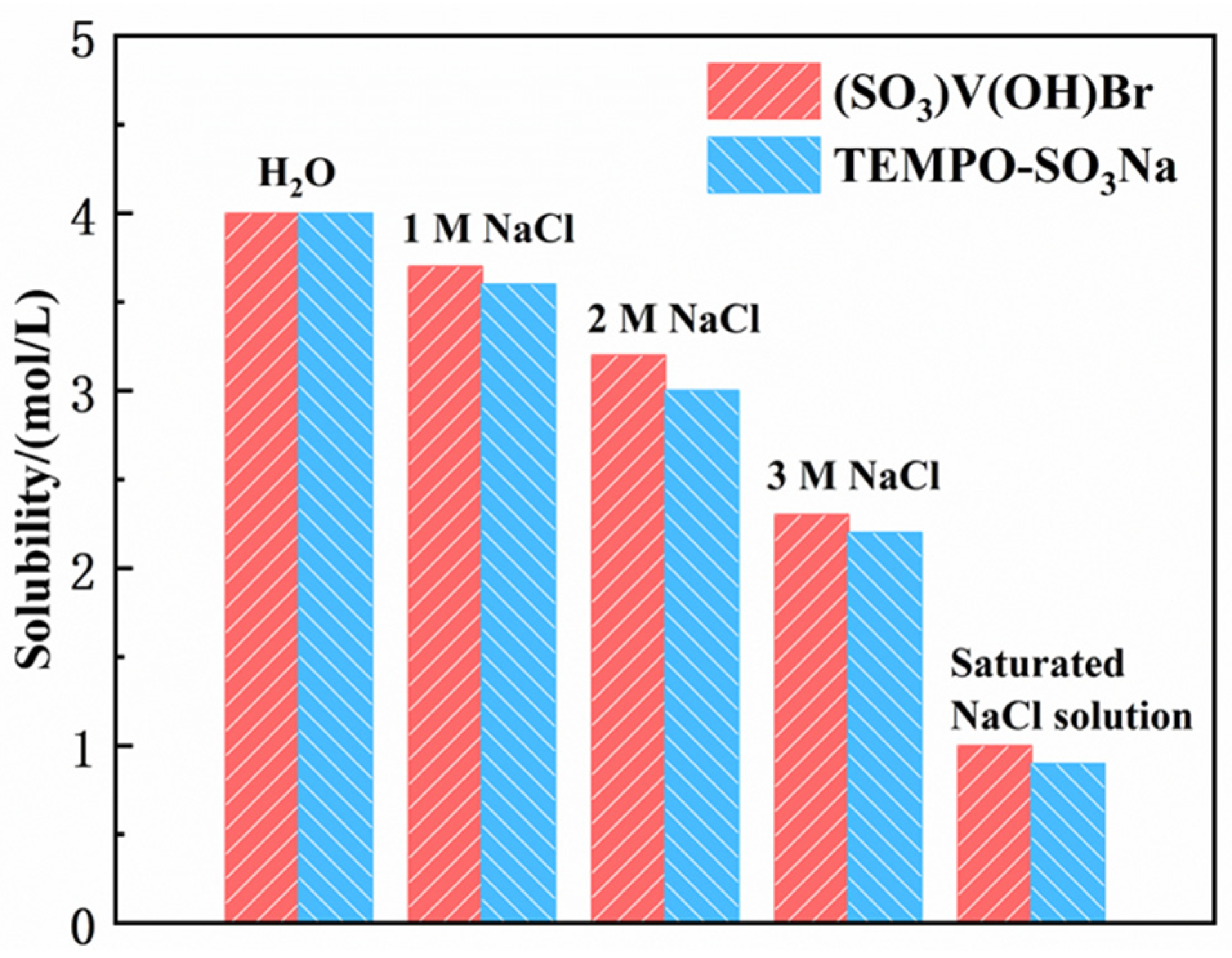
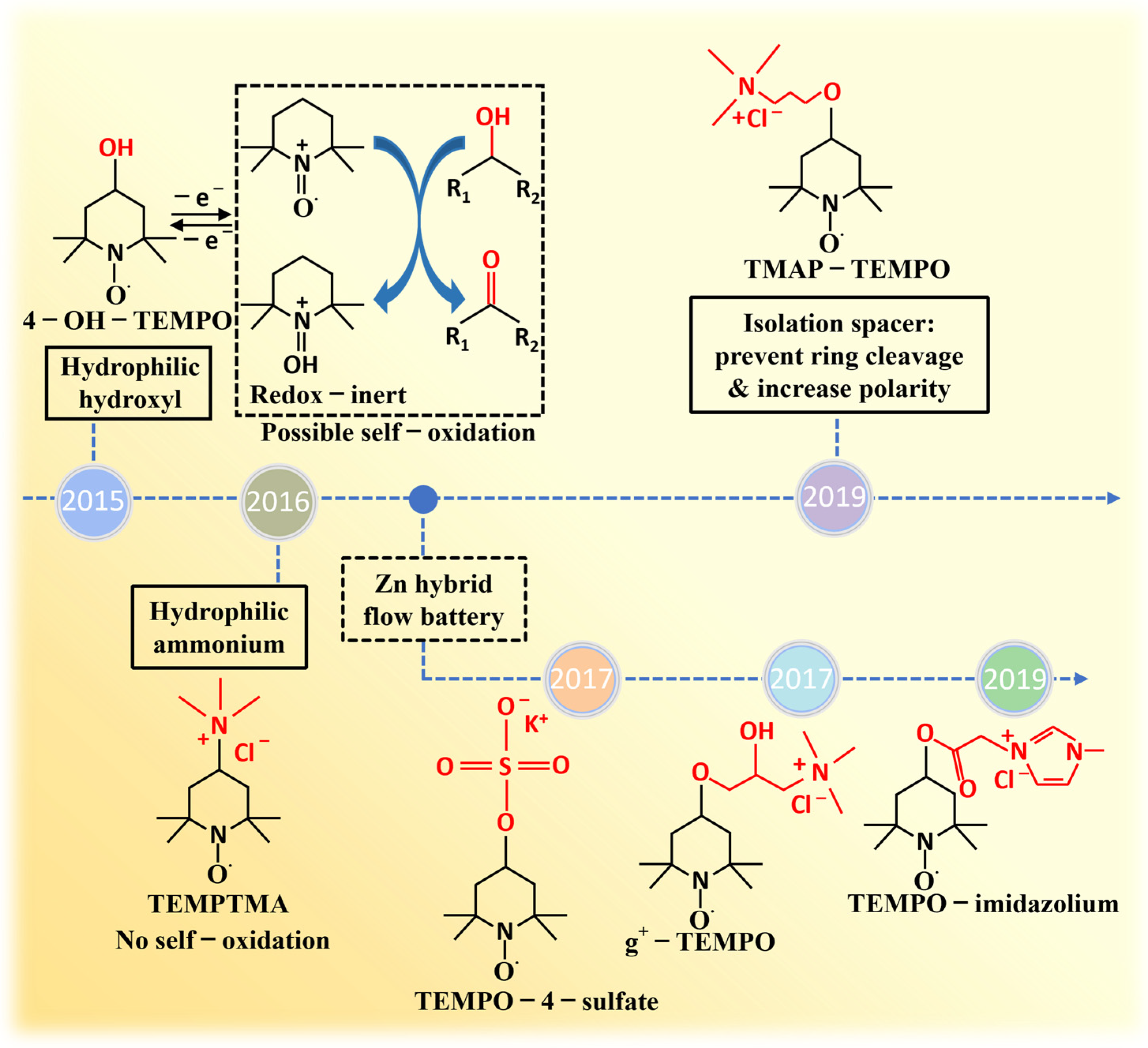
Combined with the commercial demonstration project of German battery company Jena Batteries GmbH and the first domestic aqueous organic flow battery energy storage project constructed by Suqian Time Energy Storage Technology Co., Ltd., it is believed that aqueous flow batteries with energy density ≥ 30 W·h/L, energy efficiency ≥ 80%, and cycle capacity decay ≤ 0.05%/d are expected to compete in the long-time energy storage market. Nonetheless, a review of Table 1 suggests that current flow batteries with NaCl as the supporting electrolyte do not fulfill these criteria. It is worth mentioning that the electrochemical properties of the positive and negative electrolytes in Table 1 are obtained from unsaturated NaCl solutions. As shown in Figure 6, taking TEMPO-SO3Na and (SO3)V(OH)Br as examples [50], the solubility of (SO3)V(OH)Br is 4.0 M in water, 3.7 M in 1 M NaCl, 3.2 M in 2 M NaCl, 2.3 M in 3 M NaCl, and 1 M in saturated NaCl solution, respectively. In comparison, the solubility of TEMPO-SO3Na is 4.0 M in water, 3.6 M in 1 M NaCl, 3.0 M in 2 M NaCl, 2.2 M in 3 M NaCl, and 0.9 M in saturated NaCl solution, respectively. The findings presented in Figure 7 demonstrate a gradual decline in the solubility of both compounds as the concentration of the supporting electrolyte increased. This observation has been noted to have an adverse effect on the electrochemical performance of the compounds, emphasizing the significance of enhancing the solubility of the positive and negative electrolytes in the saturated NaCl solution in the practical application of SCFB. These results have important implications for the engineering of SCFB, highlighting the need for further research and development in this area. Notably, despite the absence of positive and negative electrolytes that meet practical engineering demands, researchers in the field of flow batteries have made a crucial breakthrough by identifying a pair of electrolytes that exhibit superior overall performance compared to other counterparts [18]. Specifically, this innovative pair comprises viologen derivatives as the negative electrolytes and (2,2,6,6-tetramethylpiperidin-1-yl) oxyl (TEMPO) derivatives as the positive electrolytes, as shown in Figure 8 and Figure 9. Such a finding represents a promising avenue for the development of electrolytes that can meet the needs of large-scale SCFB applications. In particular, the successful implementation of SCFB projects are contingent upon the comprehensive enhancement of the electrochemical performance of flow batteries utilizing NaCl as the supporting electrolyte. Essential attention must be devoted not only to optimizing the energy density, power density, and cyclic capacity decay of flow batteries, but also to the advancement of high-performance ionic membranes and high-conductivity electrode materials tailored for NaCl as the supporting electrolytes. Substantial advancement in these realms is imperative for the accomplishment of SCFB engineering projects.

3.2. Permeability of Electrolytes in Surrounding Rock

The construction of salt caverns in China involves layered salt rock formations that inherently possess interlayer characteristics [74]. However, the permeability of the interlayers in the surrounding rock of the salt cavern is generally several orders of magnitude higher than that of the salt rock. As shown in Figure 10, the surface of the interlayer sample with a medium salt content rate was severely dissolved after undergoing brine immersion tests. The basic structure had undergone severe erosion damage, mainly due to the combined action of dissolution of the salt rock and water absorption and expansion of the clay minerals [75]. Therefore, special attention needs to be paid to the penetration of electrolytes in the interlayer. Given the differences in the chemical composition and properties between the electrolytes and brine, the permeability of brine in the interlayers cannot serve as a surrogate for that of the electrolytes. The potential penetration of electrolytes with differing properties from brine between the interlayers and the salt layers is therefore a crucial consideration.
Figure 10 illustrates a schematic diagram of interlayer permeability in salt caverns, and it is imperative to investigate the extent of such permeation, which should not exceed the stratigraphic distance of adjacent salt caverns. Because the electrolytes in the adjacent salt caverns, especially the electrolytes of positive and negative, cannot be mixed with each other [76], the problem of crossover between positive and negative electrolytes occurs mainly between underground salt caverns. The channels for crossover are underground pores or cracks. In stacks, the crossover between the positive electrolyte and the negative electrolyte does not occur due to the presence of ion exchange membranes. The ion exchange membrane serves as an effective barrier layer toward active species to avoid continuous crossover and self-discharge [77]. The intermixing of positive and negative electrolytes not only seriously damages the overall efficiency of SCFB, but also leads to the scrapping of the existing electrolytes and the need for a new electrolyte. Notably, the mixing of electrolytes due to permeation can lead to catastrophic outcomes, rendering salt caverns unusable for storing electrolytes. Hence, it is necessary to give attention to the electrolyte’s permeability between interlayers and between the interlayers and the salt layers, which corresponds to a safe spacing between adjacent salt caverns. The density of the electrolytes with the NaCl solution as the supporting electrolyte is 1.1 g/cm3, which is similar to brine. Therefore, to some extent, the penetration range of the electrolyte in the salt cavern can be referred to the penetration range of brine in the salt cavern, which is about 28.37 m in the salt cavern for 3 years. The penetration range of brine in the strata is approximated as a power function with time, which gradually increases with time and eventually stabilizes. The design of the actual working conditions regarding the safe mine pillar distance is generally two to three times the maximum diameter of the salt cavern. Such a safety pillar design requirement can also be referred to in the SCFB system.

3.3. Electrolytes Corrosion on Casing Tube

In the context of oil and gas field engineering, the localized corrosion of the casing tube, particularly pore corrosion, is significantly impacted by the presence of Cl ions [78]. This is due to the small radius of Cl ions and their strong ability to penetrate. Cl ions can infiltrate through the protective oxide film on the metal’s surface, penetrating fine pores or defects, and become the positive dissolution zone. Cl ions outcompete other ions in migrating to the positive, creating a high concentration of ions around the positive dissolution zone. As a result, the pH of the solution around the positive dissolution zone decreases, leading to metal dissolution in the positive dissolution zone. Consequently, Cl ions serve as a catalyst for corrosion. Moreover, the concentration of Cl ions in water is positively correlated with the degree of corrosion. And in SCFBs, the casing tube is in direct contact with the brine or electrolytes, whether in the cavern-building stage of brine injection and ejection or in the operation stage of electrolyte circulation flow. The saturated brine can induce certain corrosion into the casing tube [79].
While N80 steel grade casing tubes meet the requirements for the cavern-building stage based on current engineering experience, it is uncertain whether active materials in the electrolytes contribute to additional corrosion of the N80 steel grade casing tube. Therefore, the material for the casing tube must meet the corrosion resistance requirements of both the cavern-building and operation stages. In conclusion, the material selected for the casing tube should be chosen in such a way that the wall thickness cannot be thinned, perforated, or fractured due to corrosion during the whole process of the cavern-building and operation phases. While meeting production needs, materials should be as economical as possible.

3.4. Concentration of Active Materials

The electrochemical reactions of flow batteries are based on the redox reactions of active materials in the positive and negative electrolytes on bipolar plates. This implies that energy storage or release in flow batteries occurs through the oxidation reduction reactions of active materials in the electrolytes. The carriers of redox reactions are the ions of the electrolyte. Therefore, the energy in the charging process of the flow battery is stored in the ions. Ions can suffer from low concentration and uneven distribution in huge salt caverns. When the concentration of ions is too low, the energy stored in the ions is not released high enough, resulting in poor electrochemical performance of the flow battery. Therefore, the concentration of active materials is crucial for the electrochemical performance of flow batteries [80]. In addition, the good electrochemical performance of the SCFB system is also related to the carbon fiber electrode because it provides a reaction site for the electrolyte to undergo redox reaction [81]. During the reaction process, hydrogen evolution occurs at the negative end. This not only affects the overall electrochemical performance, but also causes wear and tear on equipment and materials [82]. The deposition of bismuth can be a possible approach to realize the above-mentioned target. Currently, the electrolytes of flow batteries are stored in tanks on the ground. To avoid adverse effects on the concentration of active materials, the size of the aboveground tanks has been reduced and the number of tanks has been increased. However, individual salt cavern cavities formed by solution mining can have a net volume ranging from hundreds of thousands to millions of cubic meters. For instance, the salt cavern gas storage in Jintan has a net volume of 215,500 cubic meters and the salt cavern gas storage in Qianjiang has a net volume of 380,000 cubic meters [24]. Although the huge volume of salt caverns matches the high-capacity requirements of flow batteries, it can adversely affect the concentration of active materials within the caverns. This is because the charging and discharging processes of flow batteries rely on the redox reactions of active materials. If the large volume of salt caverns results in low and uneven distribution of active materials, the efficiency during charging or discharging processes may decrease, leading to poorer electrochemical performance that fails to meet industrial application requirements. Therefore, enhancing the concentration of active species within salt caverns is a critical prerequisite for the industrial application of SCFB systems.

4. A Novel System of SCFB

Based on Section 2 and Section 3 concerning the key issues in constructing SCFBs in China, particularly the issue related to the low and uneven distribution of active materials in large-volume salt caverns, a novel SCFB system is proposed to address this issue. The special feature of this novel system is the deployment of two salt caverns at either the positive or negative electrode end. The two salt caverns at the same electrode end are used to store electrolytes before and after the redox reaction, enabling electrolytes of the same valence state to be stored within the same cavern, which helps to maintain a high concentration and uniform distribution of the electrolytes within the cavern, ensuring good electrochemical performance during the discharge processes.

4.1. Operation Process of the Novel SCFB System

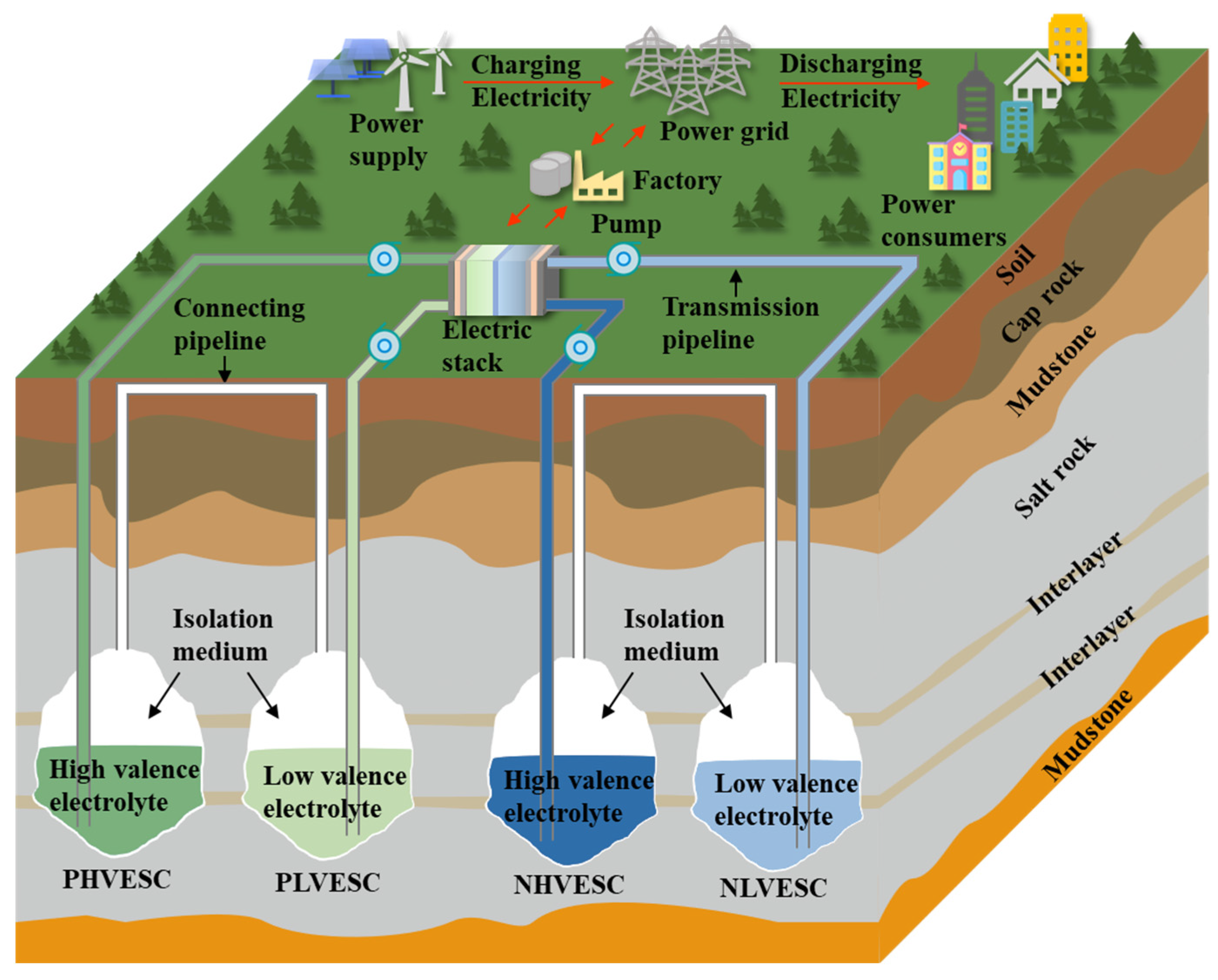
The schematic diagram of the novel SCFB system proposed in this study is shown in Figure 11 [83]. The novel SCFB system consists of two parts: the aboveground system and the underground system. The aboveground system mainly consists of the power supply, power grid, power consumers, pump, electric stack, transmission pipeline, and connecting pipeline. The underground system mainly consists of an isolation medium, transmission pipeline, connecting pipeline, positive high-valence electrolyte salt cavern (PHVESC), positive low-valence electrolyte salt cavern (PLVESC), negative high-valence electrolyte salt cavern (NHVESC), and negative low-valence electrolyte salt cavern (NLVESC). The function of the pump is to squeeze the isolation medium into the salt cavern, thus driving the electrolytes’ flow to the ground stack for redox reaction. The energy consumption of the pump will not exceed 5% of the energy efficiency of the SCFB system [45]. The electric stack consists of the collector, end plate, electrode, and ion exchange membrane. It serves to receive external electrical energy [84] and acts as a fixing device. At the same time, it provides reaction sites for the active materials of the positive and negative [85], and isolates the positive and negative active materials [86]. To collect the highest possible concentration of electrolytes, the electrolytes before and after the redox reaction are stored separately in different salt caverns during the charge and discharge processes, respectively. All of the electrolytes in SCFB are supported by the NaCl solution as the supporting electrolyte, while the transmission pipelines and connecting pipelines are made of materials with adequate corrosion resistance. The capacity of salt caverns in the same electrode is kept nearly equal. It should be noted that the isolation medium is filled with PHVESC and NLVESC before the SCFB is charged, and the positive low-valence electrolytes and the negative high-valence electrolytes are also almost filled with the PLVESC and the NHVESC, respectively.
Specifically, the operation of the SCFB can be elucidated as follows: Upon output of electrical energy from the power supply side, the energy is conveyed to the collector via the power grid. At this time, the SCFB system is in a charging state. Subsequently, the pump transports the positive low-valence electrolytes from the PLVESC to the electrodes through the transmission pipeline at the positive electrode, where an oxidation reaction ensues, leading to the formation of the positive high-valence electrolytes. The pump then transports the positive high-valence electrolytes via the transmission pipeline to the PHVESC for storage. Upon entry of the positive high-valence electrolytes, the isolation medium in the PHVESC is compressed into the PLVESC via the connecting pipeline. With an increase in the amount of isolation medium in the PLVESC, the positive low-valence electrolytes are subjected to a downward pressure, prompting them to flow back to the electrode through the transmission pipeline and continue with the oxidation reaction to generate the positive high-valence electrolytes. This cycle continues ad infinitum.
Simultaneously, the negative electrode of the pump facilitates the transport of negative high-valence electrolytes from the NHVESC to the electrode via the transmission pipeline at the negative electrode, which triggers a reduction reaction, leading to the generation of negative low-valence electrolytes. Subsequently, the pump transports the negative low-valence electrolytes to the NLVESC for storage through the transmission pipeline. Upon the entry of the negative low-valence electrolytes, the connecting pipeline compels the compression of the isolation medium in the NLVESC, propelling it into the NHVESC. Consequently, the growing isolation medium in the NHVESC applies downward pressure on the negative high-valence electrolytes, prompting them to flow to the electrode through the transmission pipeline to trigger the reduction reaction, culminating in the formation of negative low-valence electrolytes. This cyclic process perpetuates in a repetitive manner.
The electrolytes’ flow direction during the discharge process is opposite to that observed during charge process. Specifically, the positive high-valence electrolytes are pumped from the PHVESC to the electrode through the transmission pipeline at the positive electrode. Upon reaching the electrode, a reduction reaction takes place, leading in the production of positive low-valence electrolytes. The positive low-valence electrolytes are then transported to the PLVESC through the transmission pipeline. As the positive low-valence electrolytes enter the PLVESC, they cause the isolation medium within the container to be compressed and transferred to the PHVESC through the connecting pipeline. This transfer of isolation medium from the PHVESC leads in a downward pressure on the positive high-valence electrolytes, which subsequently flow through the transmission pipeline and undergo the reduction reaction to produce positive low-valence electrolytes. This cycle repeats continuously.
Concurrently, the negative low-valence electrolytes are transported from the NLVESC to the electrode via the transmission pipeline at the negative electrode, where an oxidation reaction occurs to produce the negative high-valence electrolytes. The pump then transports it to the NHVESC through the transmission pipeline. As the negative high-valence electrolytes enters, the isolation medium in the NHVESC is compressed and transferred to the NLVESC through the connecting pipeline. This transfer of isolation medium from the NLVESC leads in a downward pressure on the negative low-valence electrolytes, which subsequently flow through the transmission pipeline and undergo the oxidation reaction to produce negative high-valence electrolytes. This cycle also repeats continuously.
Particularly, in the pursuit of enhanced energy storage capacity, the addition of salt caverns at both positive and negative electrodes can be tailored to meet specific engineering needs, such as the inclusion of four or eight salt caverns. This modification facilitates long-term energy storage without necessitating any changes to the existing SCFB infrastructure, with all salt caverns constructed via the drilling water solution method. Researchers in the underground storage and development of oil and gas have provided key technical support for the site selection, design, construction, and operation of salt cavern storages, and has been successfully applied in the construction of the project. Moreover, the utilization of abandoned salt caverns or salt mines through the process mentioned above presents a cost- and time-effective solution that enhances the overall value of these resources. Thus, the conversion of salt caverns to serve as electrolyte storage presents a considerable potential for future development.

4.2. Advantages of Novel SCFB

Energy storage technologies enable the stable operation of electricity supply, transmission, and demand sides, thereby playing a crucial role in achieving the stability of supply and demand for renewable energy generation. In China, current energy storage technologies primarily include mechanical energy storage, electrochemical energy storage, hydrogen storage, and electromagnetic energy storage (Table 2).
Currently, pumped hydro storage [87] is a resource-driven technology within mechanical energy storage, wherein electrical energy is used to transport water from lower reservoirs to higher ones through pipelines, thereby storing energy in the form of gravitational potential energy. The technology is well developed and is currently the mainstream technology for large-scale energy storage. However, its drawbacks include large unit sizes, long construction periods, and susceptibility to natural constraints, limiting its future development prospects. In recent years, compressed air energy storage has rapidly evolved. Compressed air energy storage systems [88] are categorized into two types: those constructed entirely aboveground and those utilizing salt caverns for energy storage. Both types feature large storage capacities, extended operational durations, and prolonged lifespans. However, they suffer from low energy conversion efficiencies and lengthy construction periods. Additionally, aboveground compressed air energy storage systems face the drawback of requiring significant land area. Flywheel energy storage [89] is primarily suited for short-term energy storage scenarios, offering advantages such as high frequency, efficiency, and low costs. However, its industrial application remains limited due to constraints related to low storage capacities and short discharge times.
Hydrogen energy storage [90] involves electrolyzing water to produce hydrogen and oxygen, enabling the large-scale production of hydrogen using surplus electricity. This energy is then stored as hydrogen, which can be converted back into electricity through fuel cells or other means when electrical power is insufficient. Hydrogen storage represents a novel approach with significant storage capacity, suitability for long storage cycles, and independence from specific geographical conditions. However, the widespread adoption and development of hydrogen storage face numerous barriers. Challenges range from significant technological hurdles and high costs associated with production and transportation to critical safety concerns such as flammability, leakage, and susceptibility to hydrogen embrittlement of metals. Overcoming these obstacles is crucial for realizing economically efficient and safe hydrogen storage technologies, thereby advancing hydrogen energy towards practical application and industrialization.
Supercapacitor energy storage technology [91] involves storing electrical energy-using capacitors. Similar to flywheel energy storage, it is suitable for short-term energy storage applications, but typically has an operational lifespan of only about 10 years. The main advantages of supercapacitor energy storage technology include high overall efficiency, high power density, low maintenance costs, and environmental friendliness during operation. However, due to its high cost and low energy storage density, the development of supercapacitor technology has been slow, and it has not yet matured into a widely adopted technology.
In the field of electrochemical energy storage, lithium-ion batteries, lead-acid batteries, and flow batteries have achieved significant development and maturity. Sodium-ion batteries [92], however, have yet to demonstrate cost competitiveness, and their industrial chain and production capacity are still being established, indicating a moderate level of maturity. Lithium-ion [93] and lead-acid batteries [94] have quickly commercialized due to their advantages of high energy density, rapid response, and strong environmental adaptability. However, lithium-ion batteries face limitations from scarce natural lithium resources and lower safety standards. Lead-acid batteries suffer from lower energy density and poor performance in cold environments. Flow batteries [95], characterized by high safety, long lifespan, and flexible power and capacity configurations, have seen rapid development in recent years. Among them, the most representative is the all-vanadium flow battery [96]. On 30 October 2022, the Dalian all-vanadium flow battery peak-shaving power station phase I successfully connected to the grid with a scale of 100 MW/400 MWh, and has been in stable operation for over a year. Flow batteries are challenged by large footprint, high insulation costs, and overall expense. The proposed SCFB addresses these shortcomings effectively. Salt caverns offer significant volume advantages, providing flow batteries with large capacity and reduced land use. The SCFB uses a saturated NaCl solution as a supporting electrolyte with TEMPO and MV as active materials. These materials are abundant and cost-effective in nature. Moreover, salt caverns maintain consistent temperatures similar to geological depths, eliminating the need for additional insulation when storing electrolytes, thereby reducing costs. Consequently, storing electrolytes in salt caverns enhances the competitiveness of flow batteries in large-scale energy storage.
Table 2. Comparison of different energy storage technologies in China [97,98,99].
Classification of
Energy Storage
Energy Storage
Technology
Applicable
Energy Storage Cycle
Response TimeOperating LifeComprehensive
Efficiency
AdvantagesDisadvantagesMaturity LevelApplication Scenario
Mechanical energy storagePumped hydro storageHours to monthsMinute level40–60 years65–85%Higher efficiency, higher capacity, longer life, lower operating costsLong construction period, site constraints, large investmentComparatively matureBuilt along the river, peak shaving and valley filling, etc.
Compressed air energy storageHours to monthsMinute level20–40 years50–65%High capacity, long lifeLower energy efficiency conversion, large equipment investment, limited site selectionComparatively maturePeak shaving and valley filling, etc.
Flywheel energy storageSeconds to minutesMinute level10–20 years80–90%High efficiency, stabilityShort life, high cost, short energy storage timeGenerally matureSystem frequency modulation, etc.
Hydrogen energy storageHydrogen energy storageHours to quartersSecond level10–25 years<50%Long energy storage time, clean, non-pollutingInefficient, costly, explosiveImmatureFuel cells, heating, etc..
Electromagnetic energy storageSupercapacitor energy storageSeconds to hoursMinute level10–30 years85–95%Highly efficient, environmentally friendly, responsiveShort storage time, high cost, lower energy densityImmaturePeak shaving and valley filling, system frequency regulation, etc.
Electrochemical energy storageLithium-ion batteriesMinutes to daysHundred millisecond level5–15 years85–90%High efficiency, fast response, high energy densityHigh cost, limited lithium resources, safety risksComparatively matureDistributed energy storage, electric vehicles, etc.
Flow batteriesHours to monthsHundred millisecond level15–20 years65–85%Highly secure, flexible, responsiveHigher cost, lower energy density, large footprintGenerally maturePeak shaving and valley filling, system frequency regulation, etc.
Lead-acid batteriesMinutes to daysSecond level5–15 years70–90%Low cost, easy maintenanceLower energy density, poor low temperature performance, lower lifetimeComparatively maturePeak shaving and valley filling, system frequency regulation, etc.
Sodium-ion batteriesMinutes to daysHundred millisecond level5–10 years70–85%Low cost, high security, resourcefulLower energy density, slower charging speed, larger sizeComparatively maturePeak shaving and valley filling, system frequency regulation, etc.
Salt cavern flow batteriesHours to quartersHundred millisecond level20–30 years80–90%Low cost, small footprint, large capacityLower energy density, limited sitingGenerally matureBuilt along the salt mine, peak shaving and valley filling, etc.

5. Conclusions

Unlike the properties of storage tanks on the surface, storing electrolytes in salt caverns inevitably encounters several complex issues. This study identifies eight key issues from the perspectives of the geological characteristics of salt caverns and the properties of electrolytes. Additionally, a novel SCFB system is proposed to address the most critical among these issues. Finally, a comparative analysis of the technical parameters between SCFB energy storage technology and other storage technologies is conducted. The conclusions are as follows:
(1)
There are four key issues regarding the geologic characterization of salt caverns, namely, tightness, conductivity, ions, and ground temperature. Special attention should be given to ions other than Cl and Na+ ions in the salt caverns because of the possibility of these ions affecting the electrochemical performance of the SCFB. In addition, it is recommended that the depth of the salt caverns should not exceed 1500 m, depending on the temperature at which the electrolyte operates.
(2)
There are four key issues regarding electrolytes, namely, selection, permeability, corrosion, and concentration. Of them, the concentration of electrolytes in salt caverns is the most critical issue. The concentration of active substances is closely linked to the electrochemical performance during discharge processes, thereby determining the feasibility of engineering applications for SCFB systems.
(3)
A novel SCFB system that guarantees a high concentration of active materials in the salt caverns has been proposed. This novel system consists of both aboveground and underground components. In the underground system, two or more salt caverns are deployed at the positive or negative electrode end to store electrolytes before and after redox reactions, thereby ensuring high concentrations of active materials within the caverns.
(4)
The SCFB energy storage technology has the advantages of an ultra-large capacity, high efficiency, low cost, and fast response, making it suitable for storing GWh-level super backup power. It can provide a long-term stable power source for major engineering projects or military facilities.

Author Contributions

Conceptualization: S.H. and X.S.; Methodology: S.H., X.S. and Y.L. (Yinping Li); Data curation: S.H.; Investigation: S.H.; Writing—original draft: S.H.; Resources: Y.L. (Yinping Li), X.S. and C.Y.; Supervision: Y.L. (Yinping Li) and C.Y.; Writing—review and editing: X.S., Y.L. (Yinping Li), Y.L. (Yahua Liu) and X.L.; Project administration: X.S.; Validation: H.M.; Visualization: P.L., Y.L. (Yuanxi Liu) and M.X. All authors have read and agreed to the published version of the manuscript.

Funding

The authors wish to acknowledge the Excellent Young Scientists Fund Program of National Natural Science Foundation of China (No. 52122403), Youth Innovation Promotion Association CAS (No. Y2023089), National Natural Science Foundation of China (No. 52374069, No. 52304069, No. 52304070 and No. 52208342), and supported by Jiangxi Provincial Natural Science Foundation (20242ACB214008, 20232BAB204072).

Data Availability Statement

Data will be made available on request.

Conflicts of Interest

The authors declare that they do not have any commercial or associative interest that represent conflicts of interest in connection with the work submitted.

References

  1. Wegener, L. Can the Paris Agreement Help Climate Change Litigation and Vice Versa? Transnatl. Environ. Law 2020, 9, 17–36. [Google Scholar] [CrossRef]
  2. Yun, G. China’s response to climate change issues after Paris Climate Change Conference. Adv. Clim. Chang. Res. 2016, 7, 235–240. [Google Scholar]
  3. Shu, Z.; Jin, J.; Zhang, J.; Wang, G.; Lian, Y.; Liu, Y.; Bao, Z.; Guan, T.; He, R.; Liu, C.; et al. 1.5 °C and 2.0 °C of global warming intensifies the hydrological extremes in China. J. Hydrol. 2024, 635, 131229. [Google Scholar] [CrossRef]
  4. Preston, B.J. The Influence of the Paris Agreement on Climate Litigation: Causation, Corporate Governance and Catalyst (Part II). J. Environ. Law 2020, 33, 227–256. [Google Scholar] [CrossRef]
  5. Lacis, A.A.; Schmidt, G.A.; Rind, D.; Ruedy, R.A. Atmospheric CO2: Principal Control Knob Governing Earth’s Temperature. Science 2010, 330, 356–359. [Google Scholar] [CrossRef]
  6. Chen, L.; Msigwa, G.; Yang, M.; Osman, A.; Fawzy, S.; Rooney, D.W.; Yap, P.S. Strategies to achieve a carbon neutra1 society a review. Environ. Chem. Lett. 2022, 20, 2277–2310. [Google Scholar] [CrossRef]
  7. Friedlingstein, P.; Andrew, R.M.; Rogelj, J.; Peters, G.P.; Canadell, J.G.; Knutti, R.; Luderer, G.; Raupach, M.R.; Schaeffer, M.; Van Vuuren, D.P. Persistent growth of CO2 emissions and implications for reaching climate targets. Nat. Geosci. 2014, 7, 709–715. [Google Scholar] [CrossRef]
  8. Guan, D.; Liu, Z.; Geng, Y.; Lindner, S.; Hubacek, K. The gigatonne gap in China’s carbon dioxide inventories. Nat. Clim. Chang. 2012, 2, 672–675. [Google Scholar] [CrossRef]
  9. He, L.; Wang, B.; Xu, W.; Cui, Q.; Chen, H. Could China’s long-term low-carbon energy transformation achieve the double dividend effect for the economy and environment? Energy Policy 2021, 183, 20128–20144. [Google Scholar] [CrossRef]
  10. Zhou, X.; Zhang, J.; Li, J. Industrial structural transformation and carbon dioxide emissions in China. Energy Policy 2013, 57, 43–51. [Google Scholar] [CrossRef]
  11. Bloch, H.; Rafiq, S.; Salim, R. Coal consumption, CO2 emission and economic growth in China: Empirical evidence and policy responses. Energy Econ. 2012, 34, 518–528. [Google Scholar] [CrossRef]
  12. Sun, J.; Li, G.; Wang, Z. Optimizing China’s Energy Consumption Structure under Energy and Carbon Constraints. Struct. Chang. Econ. Dyn. 2018, 47, 57–72. [Google Scholar] [CrossRef]
  13. Wang, Y.F.; Li, K.P.; Xu, X.M.; Zhang, Y.R. Transport energy consumption and saving in China. Renew. Sustain. Energy Rev. 2014, 29, 641–655. [Google Scholar] [CrossRef]
  14. Suo, C.; Li, Y.P.; Nie, S.; Lv, J.; Ma, Y. Analyzing the effects of economic development on the transition to cleaner production of China’s energy system under uncertainty. J. Clean. Prod. 2020, 279, 123725. [Google Scholar] [CrossRef]
  15. Beh, E.S.; De Porcellinis, D.; Gracia, R.L.; Xia, K.T.; Gordon, R.G.; Aziz, M.J. A Neutral pH Aqueous Organic–Organometallic Redox Flow Battery with Extremely High Capacity Retention. ACS Energy Lett. 2017, 2, 639–644. [Google Scholar] [CrossRef]
  16. McGlade, C.; Ekins, P. The geographical distribution of fossil fuels unused when limiting global warming to 2 degrees C. Nature 2015, 517, 187–190. [Google Scholar] [CrossRef]
  17. Dunn, B.; Kamath, H.; Tarascon, J.M. Electrical energy storage for the grid: A battery of choices. Science 2011, 334, 928–935. [Google Scholar] [CrossRef]
  18. Chen, Q.; Lv, Y.; Yuan, Z.; Li, X.; Yu, G.; Yang, Z.; Xu, T. Organic Electrolytes for pH-Neutral Aqueous Organic Redox Flow Batteries. Adv. Funct. Mater. 2021, 32, 2108777. [Google Scholar] [CrossRef]
  19. Gangopadhyay, A.; Seshadri, A.K.; Sparks, N.J.; Toumi, R. The role of wind-solar hybrid plants in mitigating renewable energy-droughts %J TERI information digest on energy and environment: TIDEE. Renew. Energy 2022, 21, 277. [Google Scholar]
  20. Alam, M.J.E.; Muttaqi, K.M.; Sutanto, D. Battery Energy Storage to Mitigate Rapid Voltage/Power Fluctuations in Power Grids Due to Fast Variations of Solar/Wind Outputs. IEEE Access 2021, 9, 12191–12202. [Google Scholar] [CrossRef]
  21. Schdler, Y.; Renken, V.; Sorg, M.; Gerdes, L.; Fischer, A. Power transport needs for the German power grid for a major demand coverage by wind and solar power. Energy Strategy Rev. 2021, 34, 100626. [Google Scholar] [CrossRef]
  22. Sun, C.; Negro, E.; Vezzù, K.; Pagot, G.; Cavinato, G.; Nale, A.; Herve Bang, Y.; Di Noto, V. Hybrid inorganic-organic proton-conducting membranes based on SPEEK doped with WO3 nanoparticles for application in vanadium redox flow batteries. Electrochim. Acta 2019, 309, 311–325. [Google Scholar] [CrossRef]
  23. Poullikkas, A. A comparative overview of large-scale battery systems for electricity storage. Renew. Sustain. Energy Rev. 2013, 27, 778–788. [Google Scholar] [CrossRef]
  24. Wu, F.; Gao, R.; Li, C.; Liu, J. A comprehensive evaluation of wind-PV-salt cavern-hydrogen energy storage and utilization system: A case study in Qianjiang salt cavern, China. Energy Convers. Manag. 2023, 277, 116633. [Google Scholar] [CrossRef]
  25. Liu, W.; Li, Q.; Yang, C.; Shi, X.; Wan, J.; Jurado, M.J.; Li, Y.; Jiang, D.; Chen, J.; Qiao, W.; et al. The role of underground salt caverns for large-scale energy storage: A review and prospects. Energy Storage Mater. 2023, 63, 103045. [Google Scholar] [CrossRef]
  26. Hongwei, Y.; Jinhui, D.; Wei, D.; Song, X.; Jinghui, S. China’s energy storage industry: Develop status, existing problems and countermeasures. Renew. Sustain. Energy Rev. 2017, 71, 767–784. [Google Scholar]
  27. DeBruler, C.; Hu, B.; Moss, J.; Liu, X.; Luo, J.; Sun, Y.; Liu, T.L. Designer Two-Electron Storage Viologen Anolyte Materials for Neutral Aqueous Organic Redox Flow Batteries. Chem 2017, 3, 961–978. [Google Scholar] [CrossRef]
  28. Duan, Z.N.; Qu, Z.G.; Wang, Q.; Wang, J.J. Structural modification of vanadium redox flow battery with high electrochemical corrosion resistance. Appl. Energy 2019, 250, 1632–1640. [Google Scholar] [CrossRef]
  29. Ha, S.; Gallagher, K.G. Estimating the system price of redox flow batteries for grid storage. J. Power Sources 2015, 296, 122–132. [Google Scholar] [CrossRef]
  30. Perry, M.L.; Weber, A.Z. Advanced Redox-Flow Batteries: A Perspective. J. Electrochem. Soc. 2016, 163, A5064–A5067. [Google Scholar] [CrossRef]
  31. Hou, Z.; Chen, X.; Liu, J.; Huang, Z.; Chen, Y.; Zhou, M.; Liu, W.; Zhou, H. Towards a high efficiency and low-cost aqueous redox flow battery: A short review. J. Power Sources 2024, 601, 234242. [Google Scholar] [CrossRef]
  32. Prieto-Díaz, P.A.; Trovò, A.; Marini, G.; Rugna, M.; Vera, M.; Guarnieri, M. Experiment-supported survey of inefficient electrolyte mixing and capacity loss in vanadium flow battery tanks. Chem. Eng. J. 2024, 492, 152137. [Google Scholar] [CrossRef]
  33. Zhang, Q.; Song, Y. Electrochemical analysis of electrolyte temperature and composition for all-iron redox flow battery. Int. J. Green Energy 2022, 19, 1285–1289. [Google Scholar] [CrossRef]
  34. Li, J.; Tang, Y.; Shi, X.; Wenjie, X.; Chunhe, Y. Modeling the construction of energy storage salt caverns in bedded salt. Appl. Energy 2019, 255, 113866. [Google Scholar] [CrossRef]
  35. Jinlong, L.; Xilin, S.; Shuai, Z. Construction modeling and parameter optimization of multi-step horizontal energy storage salt caverns. Energy 2020, 203, 117840. [Google Scholar]
  36. Hudec, M.R.; Jackson, M.P.A. Terra infirma: Understanding salt tectonics. Earth-Sci. Rev. 2007, 82, 1–28. [Google Scholar] [CrossRef]
  37. Cuevas, C. Pore structure characterization in rock salt. Eng. Geol. 1997, 47, 17–30. [Google Scholar] [CrossRef]
  38. Alkan, H. Percolation model for dilatancy-induced permeability of the excavation damaged zone in rock salt. Int. J. Rock Mech. Min. Sci. 2009, 46, 716–724. [Google Scholar] [CrossRef]
  39. Ghanbarzadeh, S.; Hesse, M.A.; Prodanovic, M.; Gardner, J. Deformation-assisted fluid percolation in rock salt. Science 2015, 350, 1069–1072. [Google Scholar] [CrossRef]
  40. Koelemeijer, P.J.; Peach, C.J.; Spiers, C.J. Surface diffusivity of cleaved NaCl crystals as a function of humidity: Impedance spectroscopy measurements and implications for crack healing in rock salt. J. Geophys. Res. Solid Earth 2012, 117. [Google Scholar] [CrossRef]
  41. Li, S.Y. Rheology of rock salt for salt tectonics modeling. Pet. Sci. 2016, 13, 712–724. [Google Scholar] [CrossRef]
  42. Liu, X.; Shi, X.; Li, Y.; Li, P.; Zhao, K.; Ma, H.; Yang, C. Maximum gas production rate for salt cavern gas storages. Energy 2021, 234, 121211. [Google Scholar] [CrossRef]
  43. Liu, Y.; Chen, Q.; Sun, P.; Li, Y.; Xu, T. Organic Electrolytes for Aqueous Organic Flow Batteries. Mater. Today Energy 2021, 20, 100634. [Google Scholar] [CrossRef]
  44. Available online: https://newatlas.com/brine4power-largest-redox-flow-battery/50405/ (accessed on 10 July 2017).
  45. Ding, B.; Chen, J.; He, Y.; Liu, W.; Chen, L.; Xu, J.; Rui, Y. Feasibility analysis of underground flow battery storage in bedded salt rocks of China. J. Energy Storage 2023, 68, 107520. [Google Scholar] [CrossRef]
  46. Wang, J.; Li, P.; Bai, W.; Lu, J.; Fu, X.; Fu, Y.; Shi, X. Mechanical Behavior of Sediment-Type High-Impurity Salt Cavern Gas Storage during Long-Term Operation. Energies 2024, 17, 3983. [Google Scholar] [CrossRef]
  47. Liang, X.; Ma, H.; Cai, R.; Zhao, K.; Wang, X.; Zheng, Z.; Shi, X.; Yang, C. Study of Impact of Sediment on the Stability of Salt Cavern Underground Gas Storage. Energies 2023, 16, 7825. [Google Scholar] [CrossRef]
  48. Portarapillo, M.; Di Benedetto, A. Risk Assessment of the Large-Scale Hydrogen Storage in Salt Caverns. Energies 2021, 14, 2856. [Google Scholar] [CrossRef]
  49. Jiang, D.; Wang, Y.; Liu, W.; Li, L.; Qiao, W.; Chen, J.; Li, D.; Li, Z.; Fan, J. Construction simulation of large-spacing-two-well salt cavern with gas blanket and stability evaluation of cavern for gas storage. J. Energy Storage 2022, 48, 103932. [Google Scholar] [CrossRef]
  50. Wang, H.; Li, D.; Xu, J.; Wu, Y.; Cui, Y.; Chen, L. An unsymmetrical two-electron viologens anolyte for salt cavern redox flow battery. J. Power Sources 2021, 492, 229659. [Google Scholar] [CrossRef]
  51. Wei, X.; Ban, S.; Shi, X.; Li, P.; Li, Y.; Zhu, S.; Yang, K.; Bai, W.; Yang, C. Carbon and energy storage in salt caverns under the background of carbon neutralization in China. Energy 2023, 272, 127120. [Google Scholar] [CrossRef]
  52. Wang, H.; Ke, W.; Wei, Z.; Li, D.; Chen, L. An In-situ Brine Solution in Salt-cavern Supported Redox-flow Battery Using Iron/Organic Materials. Chem. Lett. 2021, 50, 389–391. [Google Scholar] [CrossRef]
  53. Wei, X.; Shi, X.; Li, Y.; Li, P.; Ban, S.; Zhao, K.; Ma, H.; Liu, H.; Yang, C. A comprehensive feasibility evaluation of salt cavern oil energy storage system in China. Appl. Energy 2023, 351, 121807. [Google Scholar] [CrossRef]
  54. Shi, X.; Liu, W.; Chen, J.; Jiang, D.; Wu, F.; Zhang, J.; Jinyang, F. Softening model for failure analysis of insoluble interlayers during salt cavern leaching for natural gas storage. Acta Geotech. 2018, 13, 801–816. [Google Scholar] [CrossRef]
  55. Wei, L.; Jie, C.; Deyi, J.; Xilin, S.; Yinping, L.; Daemen, J.J.K.; Chunhe, Y. Tightness and suitability evaluation of abandoned salt caverns served as hydrocarbon energies storage under adverse geological conditions (AGC). Appl. Energy 2016, 178, 703–720. [Google Scholar] [CrossRef]
  56. Liu, W.; Zhang, Z.; Chen, J.; Jiang, D.; Wu, F.; Fan, J.; Li, Y. Feasibility evaluation of large-scale underground hydrogen storage in bedded salt rocks of China: A case study in Jiangsu province. Energy 2020, 198, 117348. [Google Scholar] [CrossRef]
  57. Wang, J.; An, G.; Shan, B.; Wang, W.; Jia, J.; Wang, T.; Zheng, X. Parameter optimization of solution mining under nitrogen for the construction of a gas storage salt cavern. J. Nat. Gas Sci. Eng. 2021, 91, 103954. [Google Scholar] [CrossRef]
  58. Fatah, A.; Al-Yaseri, A.; Theravalappil, R.; Radwan, O.A.; Amao, A.; Al-Qasim, A.S. Geochemical reactions and pore structure analysis of anhydrite/gypsum/halite bearing reservoirs relevant to subsurface hydrogen storage in salt caverns. Fuel 2024, 371, 131857. [Google Scholar] [CrossRef]
  59. Toda, K.; Watanabe, J.; Sato, M. Synthesis and ionic conductivity of new layered perovskite compound, Ag2La2Ti3O10. Solid State Ion. Diffus. React. 1996, 90, 15–19. [Google Scholar] [CrossRef]
  60. Qiu, Z.-F.; Wang, J.-J. Experimental Study on the Anisotropic Hydraulic Conductivity of a Sandstone–Mudstone Particle Mixture. J. Hydrol. Eng. 2015, 20, 04015029. [Google Scholar] [CrossRef]
  61. Sun, W.; Dai, L.; Li, H.; Hu, H.; Wu, L.; Jiang, J. Electrical conductivity of mudstone (before and after dehydration at high P-T) and a test of high conductivity layers in the crust. Am. Mineral. 2017, 102, 2450–2456. [Google Scholar] [CrossRef]
  62. Wei, X.; Shi, X.; Li, Y.; Ma, H.; Ban, S.; Liu, X.; Liu, H.; Yang, C. Analysis of the European energy crisis and its implications for the development of strategic energy storage in China. J. Energy Storage 2024, 82, 110522. [Google Scholar] [CrossRef]
  63. Minougou, J.D.; Gholami, R.; Poirier, S. A one-dimensional diffusive transport model to evaluate H2S generation in salt caverns hydrogen storage sites. Gas Sci. Eng. 2024, 126, 205336. [Google Scholar] [CrossRef]
  64. Lai, Y.Y.; Li, X.; Liu, K.; Tung, W.Y.; Zhu, Y. Stable Low-Cost Organic Dye Anolyte for Aqueous Organic Redox Flow Battery. ACS Appl. Energy Mater. 2020, 3, 2290–2295. [Google Scholar] [CrossRef]
  65. Briot, L.; Petit, M.; Cacciuttolo, Q.; Pera, M.C. Aging phenomena and their modelling in aqueous organic redox flow batteries: A review. J. Power Sources 2022, 536, 231427. [Google Scholar] [CrossRef]
  66. Huang, J.; Dong, X.; Guo, Z.; Wang, Y. Progress of Organic Electrodes in Aqueous Electrolyte for Energy Storage and Conversion. Angew. Chem. 2020, 59, 18322–18333. [Google Scholar] [CrossRef]
  67. Han, Y.; Cui, H.; Ma, H.; Chen, J.; Liu, N. Temperature and pressure variations in salt compressed air energy storage (CAES) caverns considering the air flow in the underground wellbore. J. Energy Storage 2022, 52, 104846. [Google Scholar] [CrossRef]
  68. Xie, D.; Wang, T.; Li, L.; He, T.; Chai, G.; Wang, D.; Zhang, H.; Ma, T.; Zhang, X. Temperature distribution of brine and gas in the tubing during debrining of a salt cavern gas storage. J. Energy Storage 2022, 50, 104236. [Google Scholar] [CrossRef]
  69. Liu, T.; Wei, X.; Nie, Z.; Sprenkle, V.; Wang, W. A Total Organic Aqueous Redox Flow Battery Employing a Low Cost and Sustainable Methyl Viologen Anolyte and 4-HO-TEMPO Catholyte. Adv. Energy Mater. 2016, 6, 1501449. [Google Scholar] [CrossRef]
  70. Janoschka, T.; Martin, N.; Hager, M.D.; Schubert, U.S. An Aqueous Redox-Flow Battery with High Capacity and Power: The TEMPTMA/MV System. Angew. Chem. Int. Ed. Engl. 2016, 55, 14427–14430. [Google Scholar] [CrossRef]
  71. Liu, Y.; Goulet, M.-A.; Tong, L.; Liu, Y.; Ji, Y.; Wu, L.; Gordon, R.G.; Aziz, M.J.; Yang, Z.; Xu, T. A Long-Lifetime All-Organic Aqueous Flow Battery Utilizing TMAP-TEMPO Radical. Chem 2019, 5, 1861–1870. [Google Scholar] [CrossRef]
  72. Hu, B.; DeBruler, C.; Rhodes, Z.; Liu, T.L. Long-Cycling Aqueous Organic Redox Flow Battery (AORFB) toward Sustainable and Safe Energy Storage. J. Am. Chem. Soc. 2017, 139, 1207–1214. [Google Scholar] [CrossRef] [PubMed]
  73. Luo, J.; Hu, B.; Debruler, C.; Liu, T.L. A pi-Conjugation Extended Viologen as a Two-Electron Storage Anolyte for Total Organic Aqueous Redox Flow Batteries. Angew. Chem. Int. Ed. Engl. 2018, 57, 231–235. [Google Scholar] [CrossRef] [PubMed]
  74. Liu, W.; Li, Y.; Yang, C.; Daemen, J.J.K.; Yang, Y.; Zhang, G. Permeability characteristics of mudstone cap rock and interlayers in bedded salt formations and tightness assessment for underground gas storage caverns. Eng. Geol. 2015, 193, 212–223. [Google Scholar] [CrossRef]
  75. Shi, X.; Li, Y.; Yang, C.; Qu, D. Test Study of Influence of Brine on Tensile Strength of Muddy Intercalation. Chin. J. Rock Mech. Eng. 2009, 28, 2301–2308. (In Chinese) [Google Scholar]
  76. Montero, J.; da Silva Freitas, W.; Mecheri, B.; Forchetta, M.; Galloni, P.; Licoccia, S.; D’Epifanio, A. A Neutral-pH Aqueous Redox Flow Battery Based on Sustainable Organic Electrolytes. ChemElectroChem 2022, 10, e202201002. [Google Scholar] [CrossRef]
  77. Sun, C.; Negro, E.; Nale, A.; Pagot, G.; Vezzù, K.; Zawodzinski, T.A.; Meda, L.; Gambaro, C.; Di Noto, V. An efficient barrier toward vanadium crossover in redox flow batteries: The bilayer [Nafion/(WO3)x] hybrid inorganic-organic membrane. Electrochim. Acta 2021, 378, 138133. [Google Scholar] [CrossRef]
  78. Wang, X.-P.; Shao, M.; Ye, C.-Q.; Dong, S.-G.; Du, R.-G.; Lin, C.-J. Study on effect of chloride ions on corrosion behavior of reinforcing steel in simulated polluted concrete pore solutions by scanning micro-reference electrode technique. J. Electroanal. Chem. 2021, 895, 115454. [Google Scholar] [CrossRef]
  79. Wan, L.; Wang, B.; Xie, M.; Hu, C.; Wen, Y. Prediction of corrosion life of nitrogen blanket casing in salt cavern gas storage. Energy Sci. Eng. 2022, 10, 3044–3056. [Google Scholar] [CrossRef]
  80. Koyiit, N.; Gencten, M.; Ahin, M.; Sahin, Y. A novel vanadium/cobalt redox couple in aqueous acidic solution for redox flow batteries. Int. J. Energy Res. 2020, 44, 411–424. [Google Scholar]
  81. Ruan, R.; Wang, Y.; Hu, C.; Gao, A.; Xu, L. Electrode Potential Regulation of Carbon Fiber Based on Galvanic Coupling and Its Application in Electrochemical Grafting. ACS Appl. Mater. Interfaces 2021, 13, 17013–17021. [Google Scholar] [CrossRef]
  82. Sun, C.; Vezzù, K.; Pagot, G.; Nale, A.; Bang, Y.H.; Pace, G.; Negro, E.; Gambaro, C.; Meda, L.; Zawodzinski, T.A.; et al. Elucidation of the interplay between vanadium species and charge-discharge processes in VRFBs by Raman spectroscopy. Electrochim. Acta 2019, 318, 913–921. [Google Scholar] [CrossRef]
  83. Shi, S.; Huang, S.; Li, Y.; Ma, H.; Yang, C.; Li, P. Salt Cavern Flow Battery System. U.S. Patent 18/347529, 21 July 2023. [Google Scholar]
  84. Zhang, H.; Sun, C. Cost-effective iron-based aqueous redox flow batteries for large-scale energy storage application: A review. J. Power Sources 2021, 493, 229445. [Google Scholar] [CrossRef]
  85. Li, Z.; Lu, Y.C. Material Design of Aqueous Redox Flow Batteries: Fundamental Challenges and Mitigation Strategies. Adv. Mater. 2020, 32, e2002132. [Google Scholar] [CrossRef] [PubMed]
  86. Kwabi, D.G.; Ji, Y.; Aziz, M.J. Electrolyte Lifetime in Aqueous Organic Redox Flow Batteries: A Critical Review. Chem. Rev. 2020, 120, 6467–6489. [Google Scholar] [CrossRef] [PubMed]
  87. Weber, T.; Stocks, R.; Blakers, A.; Nadolny, A.; Cheng, C. A global atlas of pumped hydro systems that repurpose existing mining sites. Renew. Energy 2024, 224, 120113. [Google Scholar] [CrossRef]
  88. Zhang, X.; Li, Y.; Gao, Z.; Chen, S.; Xu, Y.; Chen, H. Overview of dynamic operation strategies for advanced compressed air energy storage. J. Energy Storage 2023, 66, 107408. [Google Scholar] [CrossRef]
  89. Rupp, A.; Baier, H.; Mertiny, P.; Secanell, M. Analysis of a flywheel energy storage system for light rail transit. Energy 2016, 107, 625–638. [Google Scholar] [CrossRef]
  90. Nagpal, M.; Kakkar, R. An evolving energy solution: Intermediate hydrogen storage. Int. J. Hydrogen Energy 2018, 43, 12168–12188. [Google Scholar] [CrossRef]
  91. Karandikar, P.B.; Talange, D.B.; Mhaskar, U.P.; Bansal, R. Development, modeling and characterization of aqueous metal oxide based supercapacitor. Energy 2012, 40, 131–138. [Google Scholar] [CrossRef]
  92. Zhao, W.; Wang, M.; Lin, H.; Kim, K.; He, R.; Feng, S.; Liu, H. Research progress on electrolyte key salts for sodium-ion batteries. Prog. Nat. Sci. Mater. Int. 2024, 34, 263–273. [Google Scholar] [CrossRef]
  93. Zhang, J.; Ren, H.; Wang, J.; Qi, J.; Liu, Y. Engineering of multi-shelled SnO2 hollow microspheres for highly stable lithium-ion batteries. J. Mater. Chem. A 2016, 4, 17673–17677. [Google Scholar] [CrossRef]
  94. Li, M.; Liu, J.; Han, W. Recycling and management of waste lead-acid batteries: A mini-review. Waste Manag. Res. 2016, 34, 298–306. [Google Scholar] [CrossRef] [PubMed]
  95. Zhang, H.; Lu, W.; Li, X. Progress and Perspectives of Flow Battery Technologies. Electrochem. Energy Rev. 2019, 2, 492–506. [Google Scholar] [CrossRef]
  96. Guo, Y.; Huang, J.; Feng, J. Research progress in preparation of electrolyte for all-vanadium redox flow battery. J. Ind. Eng. Chem. 2022, 118, 33–43. [Google Scholar] [CrossRef]
  97. Koohi-Fayegh, S.; Rosen, M.A. A review of energy storage types, applications and recent developments. J. Energy Storage 2020, 27, 101047. [Google Scholar] [CrossRef]
  98. Tan, K.M.; Babu, T.S.; Ramachandaramurthy, V.K.; Kasinathan, P.; Solanki, S.G.; Raveendran, S.K. Empowering smart grid: A comprehensive review of energy storage technology and application with renewable energy integration. J. Energy Storage 2021, 39, 102591. [Google Scholar] [CrossRef]
  99. Hadjipaschalis, I.; Poullikkas, A.; Efthimiou, V. Overview of current and future energy storage technologies for electric power applications. Renew. Sustain. Energy Rev. 2009, 13, 1513–1522. [Google Scholar] [CrossRef]
Figure 1. Development of China’s wind and solar energy generation from 2003 to 2021 [24].
Energies 17 05190 g001
Figure 2. Wind power abandonment in China from 2010 to 2021 [24,25].
Energies 17 05190 g002
Figure 3. The construction process of underground salt caverns [25].
Energies 17 05190 g003
Figure 4. (a) Schematic diagram of Brine4Power project for SCFB in Germany [44]; (b) Ding et al. proposed a salt cavern liquid current battery system in China by combining wind energy and PV [45].
Energies 17 05190 g004
Figure 5. Key issues in building a salt cavern flow battery.
Energies 17 05190 g005
Figure 6. Schematic diagram of impurity ions caused by interlayers in the salt cavern.
Energies 17 05190 g006
Figure 7. The solubility of (SO3)V(OH)Br and TEMPO-SO3Na in various concentrations of NaCl solutions.
Energies 17 05190 g007
Figure 8. The development of 2,2,6,6-TEMPO derivatives for use in a pH-neutral aqueous organic redox flow battery.
Energies 17 05190 g008
Figure 9. The development of viologen derivatives for use in a pH-neutral aqueous organic redox flow battery.
Energies 17 05190 g009
Figure 10. Schematic diagram of the interlayer’s permeability in salt caverns.
Energies 17 05190 g010
Figure 11. Schematic diagram of the SCFB system (PHVESC means positive high-valence electrolyte salt cavern, PLVESC means positive low-valence electrolyte salt cavern, NHVESC means negative high-valence electrolyte salt cavern, and NLVESC means negative low-valence electrolyte salt cavern).
Energies 17 05190 g011
Table 1. Electrochemical performance test results of representative neutral aqueous organic flow batteries with NaCl as the supporting electrolyte.
NameCapacity Fade
(%/Cycle)
Supporting
Electrolyte
Capacity
(A·h/L)
Energy Densit
(W·h/L)
System Energy Efficiency (%)
(SO3)V(OH)Br/TEMPOSO3Na [50]0.052 M NaCl13.410.880
MV2+Cl2/4-HO-TEMPO [69]0.011 M NaCl2.683.3587
MV/TEMPTMA [70]-1.5 M NaCl543870
BTMAP-Vi/TMAPTEMPO [71]0.0071 M NaCl40.223.990
BTMAP-Vi/BTMAP-Fc [15]0.00570.5 M NaCl262065
MV/FcNCl [72]0.012 M NaCl84-60
[(NPr)2TTz]Cl4/NMe-TEMPO [73]0.032 M NaCl6053.770
Disclaimer/Publisher’s Note: The statements, opinions and data contained in all publications are solely those of the individual author(s) and contributor(s) and not of MDPI and/or the editor(s). MDPI and/or the editor(s) disclaim responsibility for any injury to people or property resulting from any ideas, methods, instructions or products referred to in the content.