Article

A New Topology of Multi-Input Bidirectional DC-DC Converters for Hybrid Energy Storage Systems

Department of Electrical, Electronic, Tlc Engineering and Naval Architecture (DITEN), University of Genova, Via All’Opera Pia 11a, 16145 Genova, Italy
*
Author to whom correspondence should be addressed.
Energies 2024, 17(20), 5120; https://doi.org/10.3390/en17205120
Submission received: 24 September 2024 / Revised: 10 October 2024 / Accepted: 13 October 2024 / Published: 15 October 2024

Abstract

:
A new topology of multi-input bidirectional DC-DC converters is proposed in this paper. The converter has a boost behavior, i.e., the output voltage is higher than the sum of the input voltages. This family of converters is particularly suited for hybrid energy storage systems, where different DC sources are connected together and where the output voltage is significantly higher than the voltage of a single storage. The proposed converter reduces the number of required switches, leading to higher efficiency and reduced complexity compared to traditional n-input converters. The new topology demonstrates superior performance by enabling higher efficiency with fewer components. A dedicated control, based on PI controllers, is provided to ensure stable operation under dynamic conditions. The effectiveness of the proposed solution is tested using experimental results on a four-input 20 A/100 V converter prototype.

1. Introduction

The increasing attention to reducing fossil fuel use and renewable energy exploitation has led to numerous studies on Energy Storage Systems (ESSs). Among the numerous types of storage systems, some are High-Power-Density Energy Storage (HPDES) systems, whereas others are High-Energy Density Energy Storage (EDES) systems. In order to combine the benefits of both ESSs, Hybrid-ESSs (HESSs) have been studied, where HPDESs (e.g., ultracapacitors or flywheels) are combined with EDESs (e.g., batteries). Several studies have been carried out in recent years on HESSs for various applications such as hybrid and electric vehicles [1,2,3,4,5,6], microgrids [7,8,9,10,11,12,13] and all-electric ships [14,15]. ESSs are usually connected to a common DC-bus with DC-DC converters [1,2,3,5,8,9,10]. When several DC sources have to be connected to a common DC-bus, as in HESSs, it may be more convenient to use a single multi-input converter instead of multiple single-input converters in parallel connection. Multi-Input Single-Output Converters (MISOCs) and Multi-Input Multi-Output Converters (MIMOCs) have been widely studied in the technical literature for several applications. Regarding mono-directional converters, non-isolated MISOCs have been studied in [16,17,18,19], whereas isolated MISOCs were proposed in [20,21]; moreover, MIMOCs have been investigated in [22,23,24,25]. In some applications, mono-directional and bidirectional sources are mixed together, e.g., fuel cells and/or photovoltaics connected to the same DC-bus of EESs.
For these scenarios, a MIMOC with both mono- and bidirectional ports was proposed in [26]. Analogously, MISOCs with mixed mono- and bidirectional inputs have been proposed in the literature, both with mono-directional [27,28] and bidirectional [29,30] output. Taking into account fully bidirectional MISOCs, which are suitable for HESS applications, new topologies with galvanic isolation were proposed in [31,32]. Regarding bidirectional non-isolated MISOCs, a new double-input buck-boost converter using only four switches was studied in [33]. An interesting n-input converter that uses n + 2 switches was shown in [34], which can work as a buck-boost with positive power flow and as a buck with negative power flow. A bidirectional boost converter architecture was proposed in [35], where an ultra-high voltage gain can be achieved by using three integrated boost cells, whereas in [36,37], a review of the main non-isolated multi-input topologies is presented from the control strategy and design perspectives, respectively. In particular, ref. [36] is focused on renewable energy applications, while [37] is focused on EVs. Although most of these topologies offer useful features, they often suffer from limitations such as a high number of switching devices or limited voltage step-up ratios, which restrict their efficiency and flexibility for some applications.
Recently, a new double-input three-switch boost converter was proposed in [38] and analyzed more recently in [39,40]. For the same three-switch converter, a new modulation strategy was developed in [41] in order to exploit Discontinuous Conduction Mode (DCM), and a feed-forward control approach was developed in [42] in order to improve the system’s dynamic performance. In this paper, a new non-isolated bidirectional multi-input boost converter topology is proposed which can be derived from the three-switch aforementioned architecture; being a boost converter, the sum of the input voltages must be lower than the output voltage. The configuration is particularly suited when a high voltage step-up functionality is required, e.g., in ESSs interfaced with the AC line and in hybrid electric vehicles. Indeed, in the case of ESSs interfaced with an AC line, the DC–DC converter output coincides with the Active Front End DC-link, which should be about 800 V in the case of a three-phase 400 V line, while, in contrast, the storage voltages are usually significantly lower. Analogously, the DC–DC converter output coincides with the motor inverter DC-link in hybrid electric vehicles; if several storage systems are used, the voltage of the single DC source is usually significantly lower than the DC-link voltage. The proposed n-input converter has the advantage of using only n + 1 switches. Compared to a traditional solution in which n half-bridges are used in parallel connection, not only does the proposed solution utilize fewer devices (n + 1 instead of 2n) but the converter efficiency is also higher, as will be demonstrated in this paper. A four-input, 20 A/100 V’ converter prototype was developed to validate the proposed topology and the related control strategy.
To summarize, traditional solutions often require a large number of switches (2n for n-input converters), which increases system complexity, switching losses, and overall inefficiency. In contrast, the proposed topology reduces the number of switches to n + 1, offering a more streamlined and efficient solution. Furthermore, the converter is designed to meet the need for high-voltage step-up applications, such as hybrid electric vehicles (HEVs) and ESSs interfaced with AC grids, where the output voltage must be significantly higher than the input voltages. This addresses a key limitation of many existing converters that struggle with limited step-up ratios, offering a more efficient, cost-effective, and simplified solution.
The paper is structured as follows: the converter and the related control are proposed in Section 2. The experimental test bench is shown in Section 3, whereas the theoretical efficiency is shown in Section 4 and compared with the efficiency of n half-bridges in parallel connection. Experimental results are reported in Section 5. Finally, conclusions are presented in Section 6.

2. Converter Structure and Control

The converter structure is shown in Figure 1. E x , with x = 1, 2, , n, refers to the n DC sources’ voltage (e.g., batteries, supercapacitors, and flywheels), whereas L x , with x = 1, 2, , n, identifies the inductance of the n inductors series-connected to the respective voltage sources. The basic module, which includes a voltage source, an inductor, and an electronic switch, is highlighted by a green ring in Figure 1. The converter consists of n modules series-connected, plus an additional electronic switch T n + 1 , which is highlighted by a red ring. The output voltage V o u t should be higher than the sum of the E x input voltages. Being n + 1 switch involved, 2n+1 switching configuration is possible. However, the configuration in which all of the switches are closed at the same time leads to output short circuits; therefore, they should be avoided. Moreover, all of the configurations in which more than one switch is opened at the same time imply that the voltages depend on the current signs. In Table 1, the 16 switching configurations are reported in the case of a four switch-converter, as an example. As mentioned above, it should be noted that the only configurations that provide unique voltage/current conditions are the switching states 2, 3, 5, and 8, i.e., the configurations in which only one switch is opened at the same time.
Considering the converter shown in Figure 1, the instantaneous voltage vx between the DC source negative pole and the inductor positive pole can be expressed as in Equation (1):
v x = E x R x i x L x d i x d t
where R x is the parasitic resistance of L x . If the switch x is closed, v x = 0 , whereas if switch x is opened, v x = V o u t , as shown in Table 1. Therefore, if the duty cycle is defined as in Equation (2), the average value of v x during one switching period can be calculated as in Equation (3).
y x = t x , o f f t s
V x = y x V o u t
where t x , o f f is the turn-off time of switch T x and t s is the switching period. Considering the average values over one switching period, (1) is modified in Equation (4)
V x = E x R x I x
where V x and I x are the average value of v x and i x , respectively, over one switching period. Combining (3) with (4), Equation (5) is obtained:
I x = y x V o u t E x R x
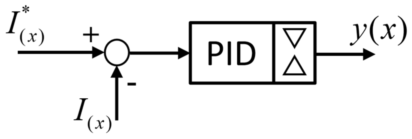
Since the current control of each source is independent of the other sources, a simple Proportional Integral Derivative (PID) controller, as shown in Figure 2, can be used to implement current control.
Since Equation (6) must hold, y n + 1 is defined by Equation (7):
i = 1 n + 1 y i = 1
y n + 1 = 1 i = 1 n y i
To sum up, one and only one switch must be opened at a time and, moreover, Equations (6) and (7) should always be verified in the Pulse-Width Modulation (PWM) command signal generation in order to ensure correct behavior. Therefore, the gate pulses of the switches should be as in Figure 3, where the case of a four-switch converter is shown, just as an example. Please note that in the gate pulses in Figure 3, dead times are neglected.
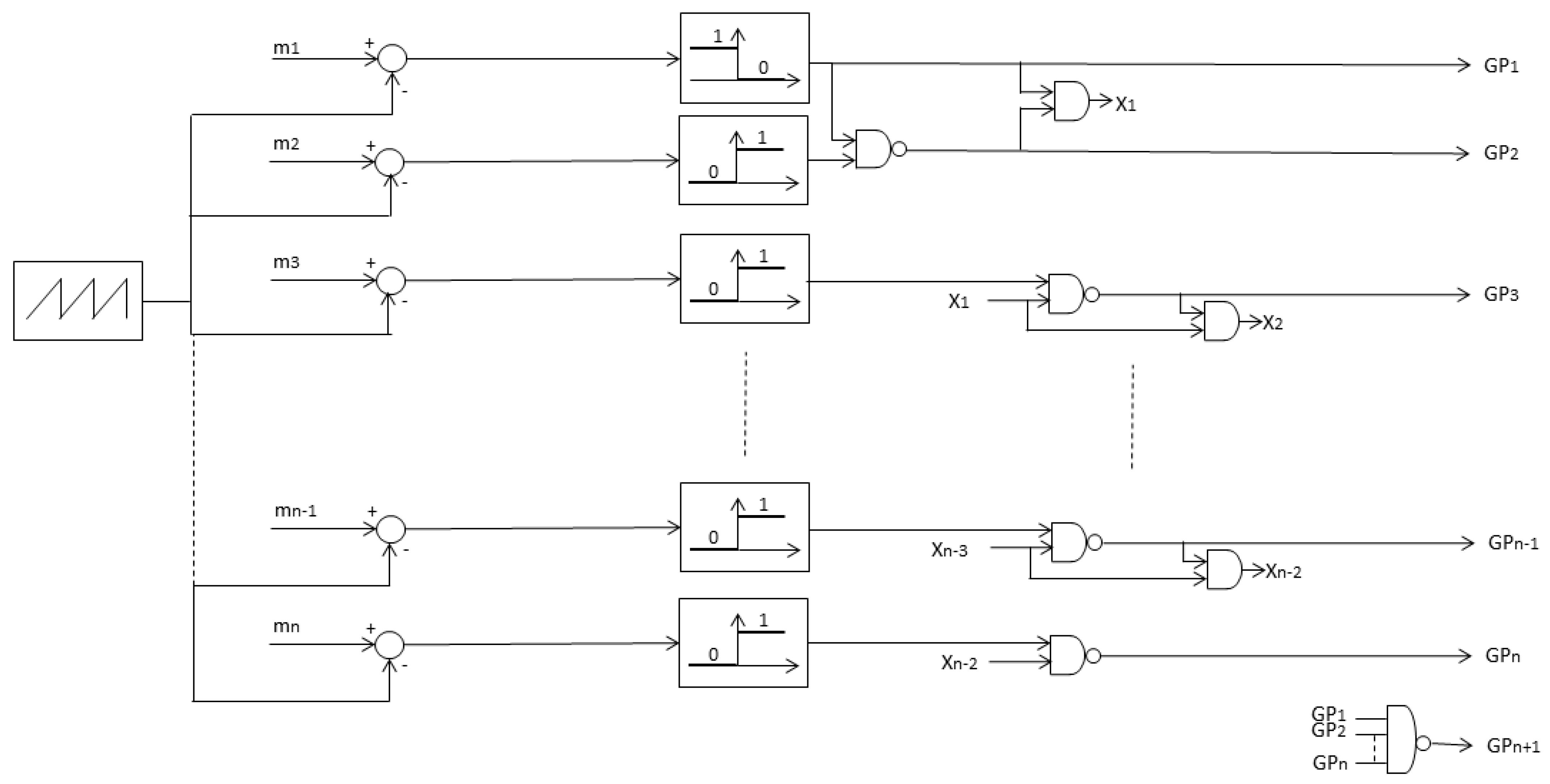
If one defines the modulation indexes mx as the sum of the duty cycles from 1 to x, as in Equation (8), the gate pulses can be obtained with the control scheme of Figure 4, where the case of a generic n + 1 switch converter is shown.
m x = i = 1 x y i

3. Experimental Test Bench

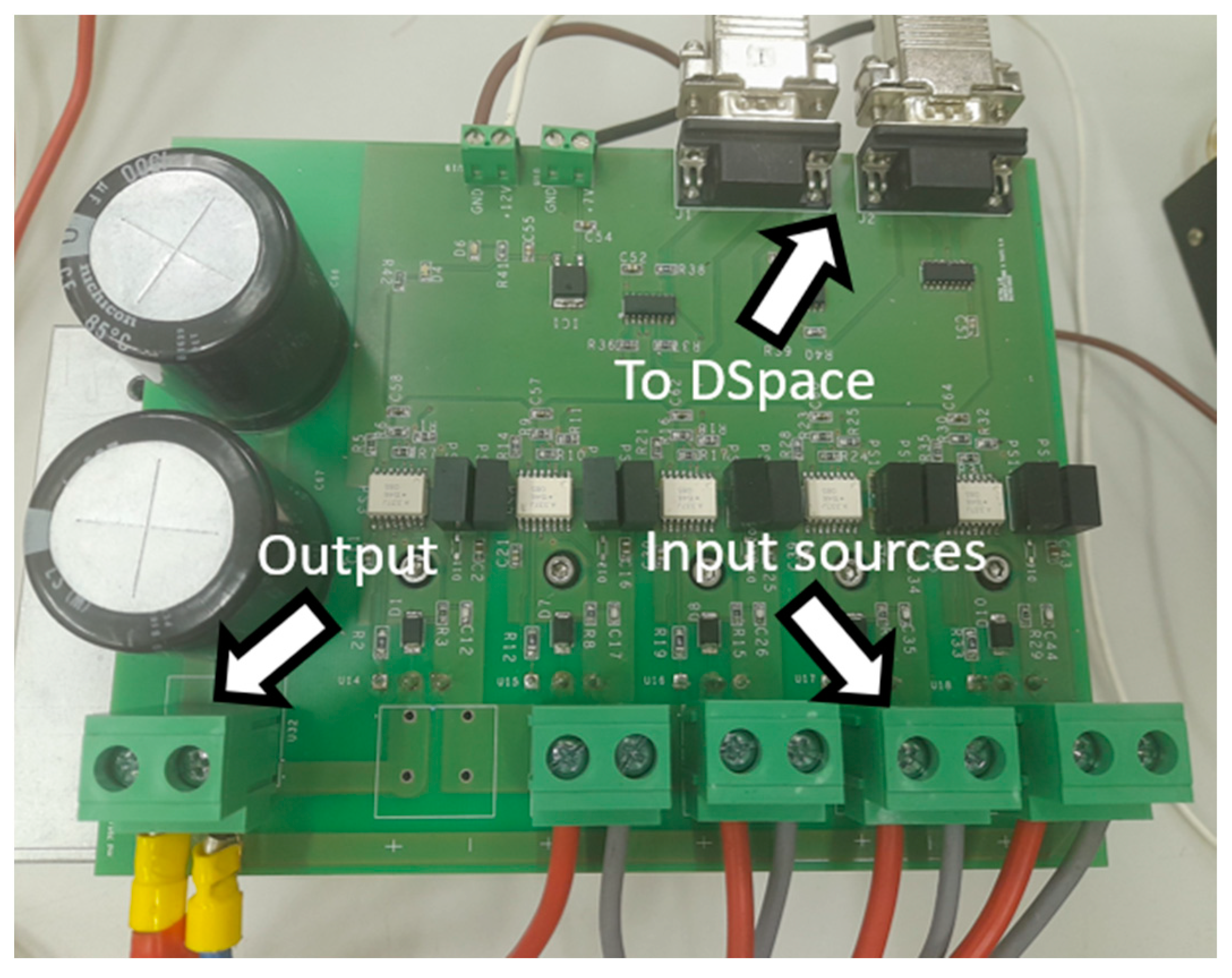
A converter prototype with five switches was designed and developed. In this configuration, the converter is able to manage four DC sources independently, i.e., each source can provide/absorb energy regardless of the power of the other sources. The converter prototype is shown in Figure 5, and it is sized to operate at 20 A/100 V, i.e., 20 A maximum for each source and 100 V as the maximum output voltage. The converter is equipped with two capacitors on the output side, whereas the four input sources with the relative inductances should be connected externally.
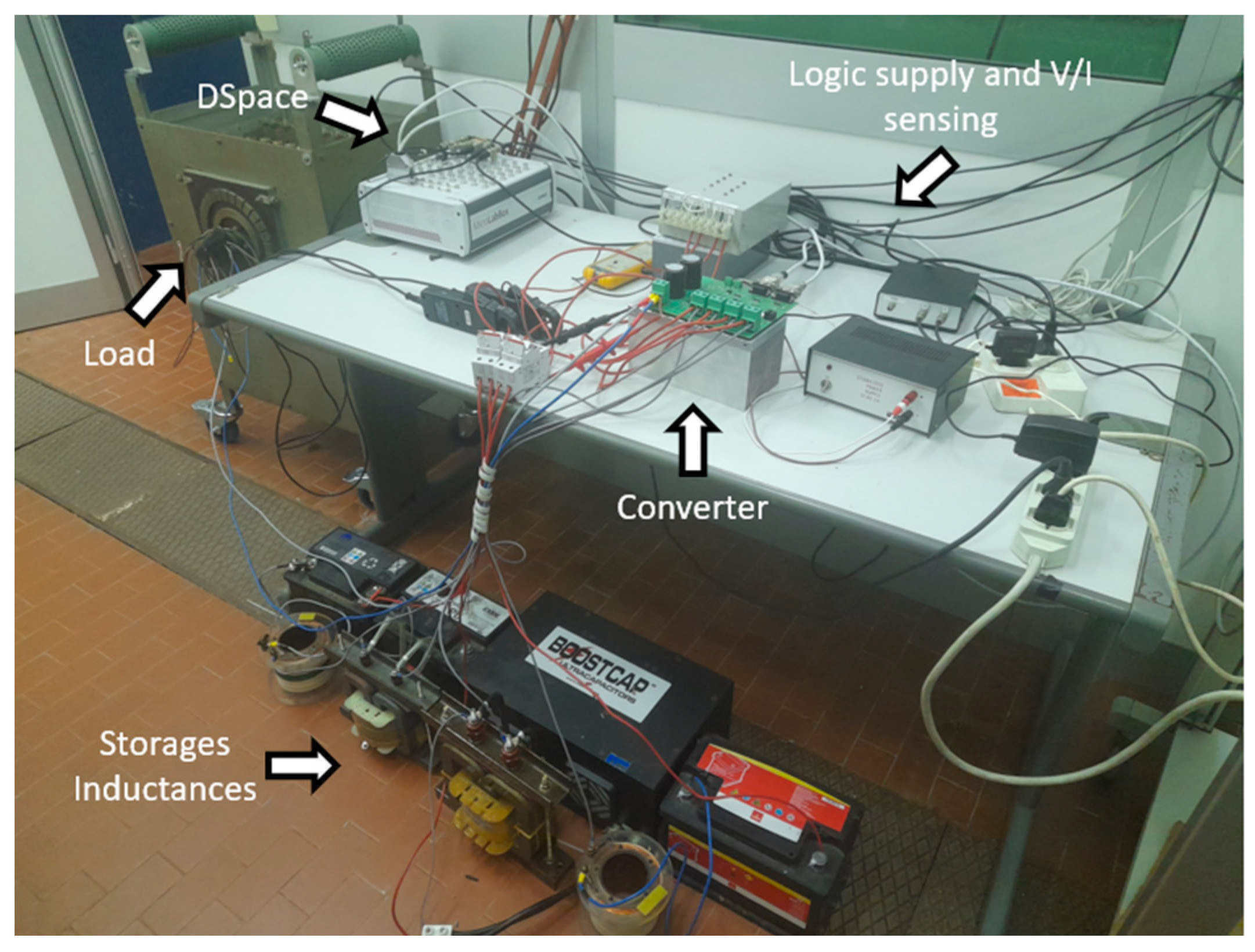
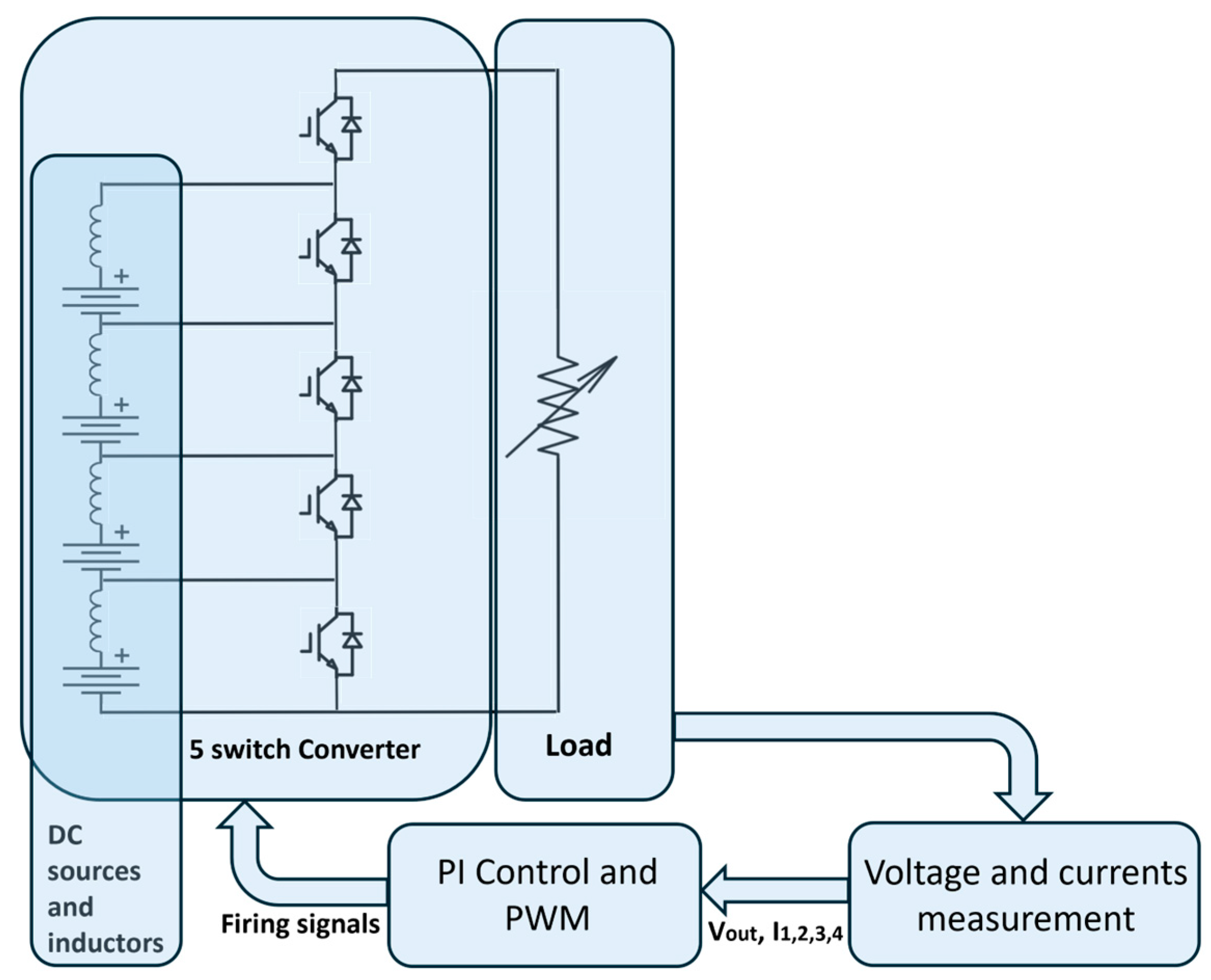
The complete test bench is reported in Figure 6. Three lead-acid batteries and a supercapacitor are used as input sources whereas a 30 Ω resistor can be connected and disconnected from the output of the converter as a load. The control is implemented in DSpace MicroLabBox. The currents are oversampled at 500 kHz, and the average value over one switching period is considered to perform the current control. DSpace MicroLabBox is used both for controlling and acquiring voltage and current waveforms. The overall control runs at the switching frequency (10 kHz). Test bench parameters are reported in Table 2, while the electrical block diagram of the experimental test bench is shown in Figure 7.

4. Efficiency Comparison between the Half-Bridge Converter and the Proposed Converter

The MOSFET Infineon IPP530N15N3G is used in the proposed converter prototype. From the producer’s datasheet, it is possible to evaluate the conduction and switching losses and to compare them with the losses of a traditional solution with n half-bridges in parallel connection. The conduction and switching losses were evaluated by implementing the thermal model of the MOSFET in the Matlab/Simulink/Plecs environment. The losses and efficiency are shown in Table 3, considering the rated working point of the converter, i.e., parameters in Table 2, with a constant current of 20 A for each storage. As can be noted from Table 3, a reduction of 44% is achievable with the five-switch converter compared to the four half-bridge converters in parallel connection.
As mentioned above, starting from the device datasheet, the switching and conduction losses of the specific MOSFET considered in this case were evaluated by incorporating its thermal model in Plecs. In particular, the output characteristic (I/V) and the switching energy loss curves ( E o n , E o f f ) during the turn-on and turn-off transitions of the considered MOSFET Infineon IPP530N15N3G were implemented in the thermal model of Plecs. Then, the losses were calculated dynamically during the simulation based on the current, voltage, and switching frequency, and the results are shown in Table 3.

5. Experimental Results

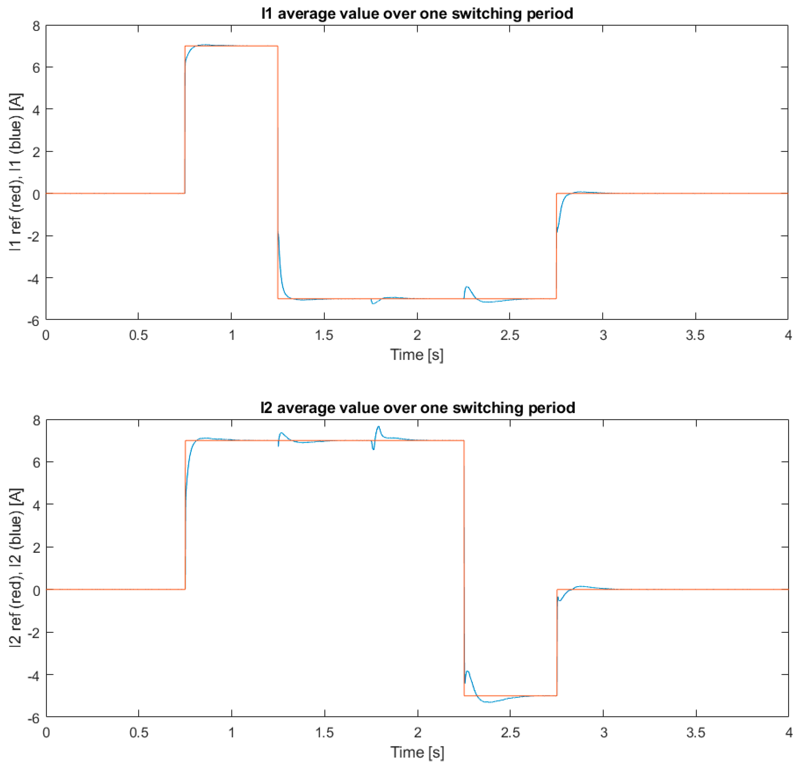
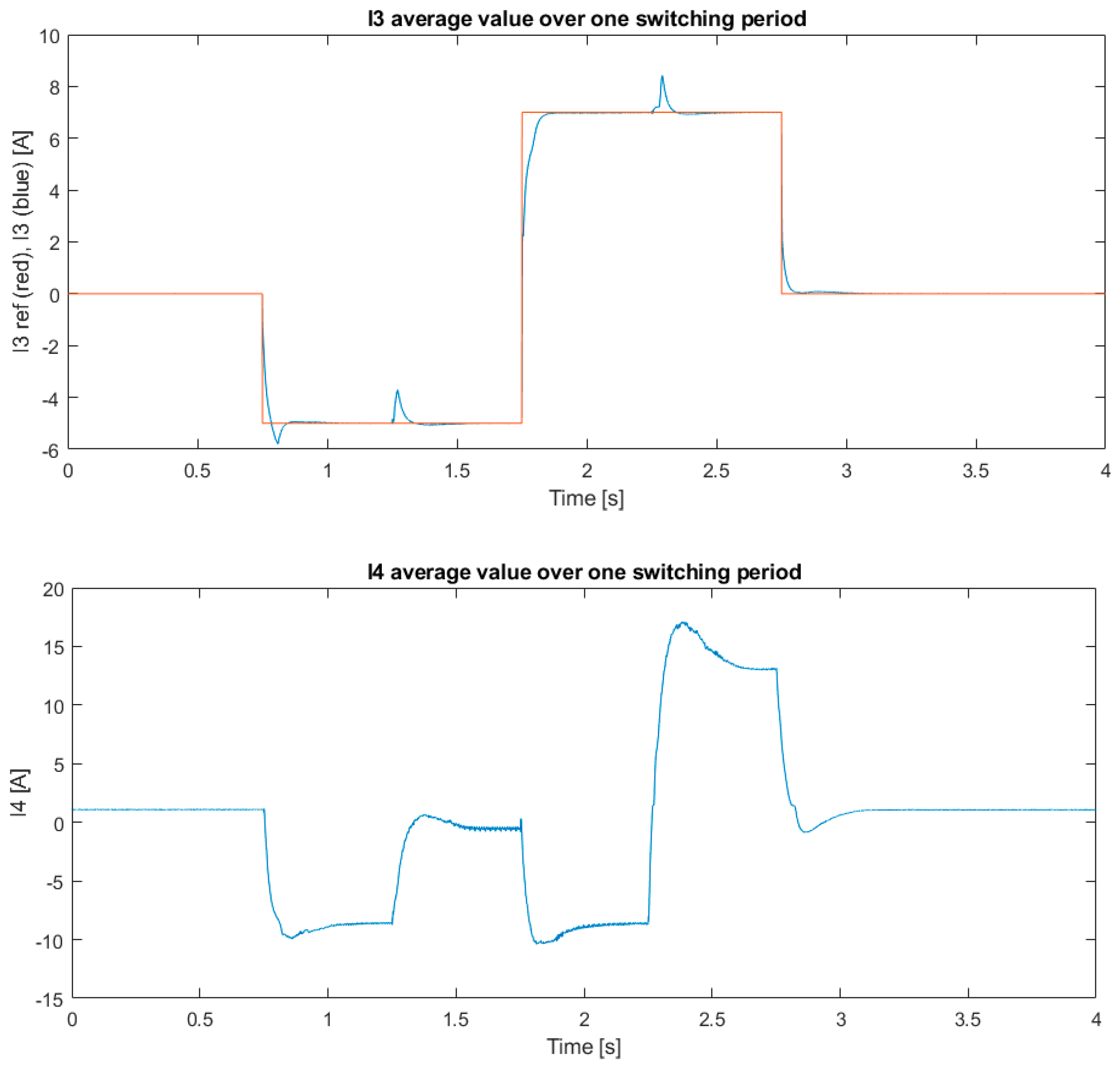
Some experimental tests were carried out on the converter prototype shown above, and some results are reported in this section. In Test 1, the I1, I2, and I3 references were set arbitrarily, whereas a voltage loop control set the I4 reference in order to keep the output voltage constant at 100 V. In more detail, a series of reference step variations were given to I1, I2, and I3, and the load was disconnected from the output. In this test, the different sources charge/discharge each other. The current references are changed every 500 ms according to Table 4. Test results are shown in Figure 8, Figure 9 and Figure 10.
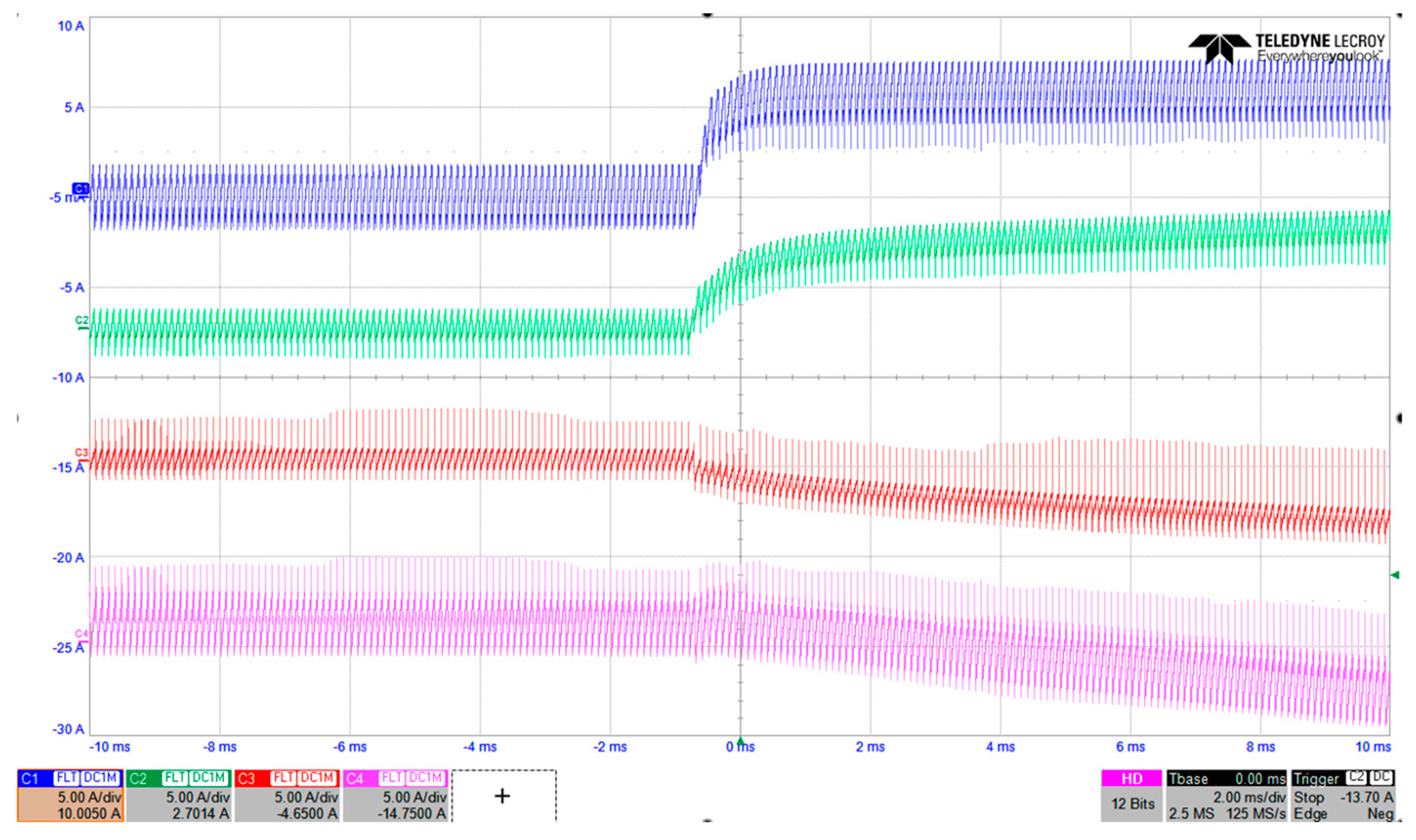
I1, I2, and I3 correctly follow their reference values, whereas I4 changes in order to keep a constant voltage output. Please note that in Figure 8, the experimental current values, averaged over one switching period, are plotted, which were obtained from the DSpace acquisition system. Therefore, one cannot appreciate the current ripples. In order to show the current ripples, an acquisition using the oscilloscope is reported in Figure 9, where the current variations at 0.75 s of Test 1 are shown. A zoomed-in version of the same point is reported in Figure 10.
Please note that the current ripple observed in the experimental waveforms is a typical and expected behavior in DC-DC converters. This ripple is due to the periodic energy transfer between the switching elements and the passive components, and its amplitude is determined by the converter parameters, including the switching frequency, inductance values, and input and output voltages. It is a typical characteristic of converter operation and does not affect overall DC performance.
Moreover, please note that the current ripple is less than 5 A peak-to-peak (less than 25% of the rated current of 20 A), which is the typical value of DC-DC converters.
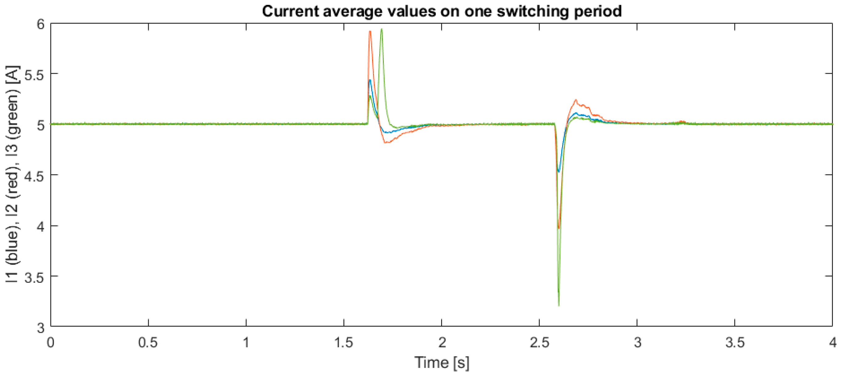
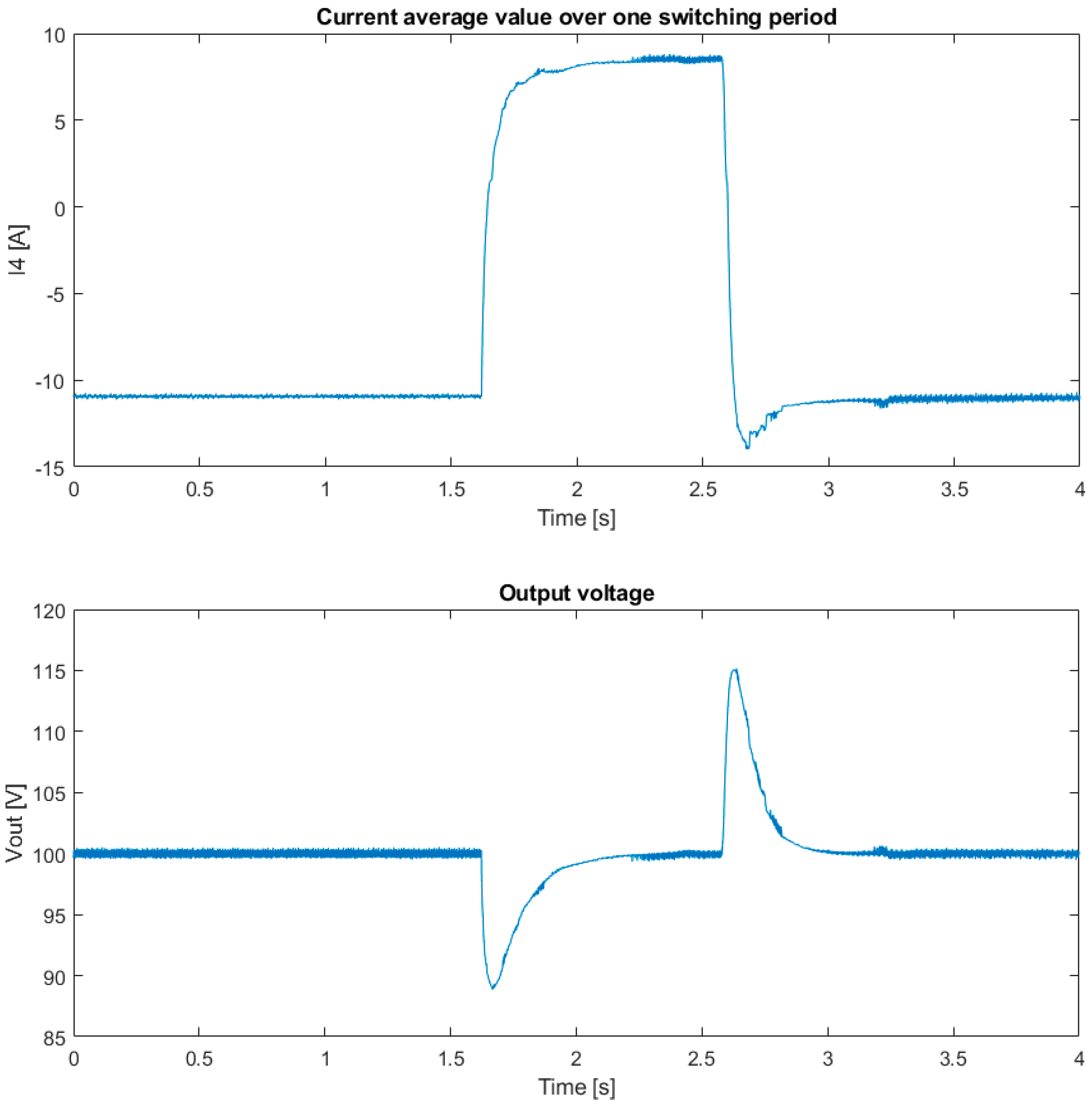
In addition, from Figure 10, some spikes can be highlighted in the four current traces. As can be seen, the spikes appear at regular intervals and repeat every switching period; moreover, they occur when one of the four currents changes slope. The spikes are caused by the switching operation of the converter. The switching frequency is 10 kHz in this case, and rapid transitions of the switching device states are reflected in the current measurements. In Test 2, the I1, I2, and I3 references are kept constant to 5 A, while the load is connected and disconnected again from the output. Test results are shown in Figure 11. At the beginning of the test, sources 1, 2, and 3 are charging source 4 since the output power is zero. When the load is applied to the converter output, source 4 starts to discharge, and all of the sources provide power to the converter output. One can note that after a short transient, I1, I2, and I3 return to the reference value of 5 A, whereas I4 changes from about −11 A to about +9 A in order to keep the output voltage constant. In addition, in the bottom part of the plots in Figure 11, it can be noted that the DC-link voltage is correctly regulated to the reference of 100 V.

6. Conclusions

Some of the most challenging aspects of multi-input non-isolated bidirectional boost converters are the high number of components, the limited step-up ratio, and the circuit and control complexity. In response to these challenges, in this paper, a new DC-DC converter topology is presented. The converter is bidirectional and has n inputs and a single output. It has a boost behavior, i.e., the sum of the input voltages has to be lower than the output voltage. Compared to a traditional solution with n half-bridges in parallel connection, it uses only n + 1 switches instead of 2n switches and, moreover, it ensures higher efficiency. In particular, with the proposed prototype, the theoretical efficiency in rated working conditions increases from 93.3% to 96.2%. A proper control was designed, and the validity of the converter and the related control was verified using experimental results on a 20 A/100 V prototype.
Among possible future developments, the potential to enhance the control of the proposed converter should be mentioned, based on the classic PI regulators in this paper, by implementing more sophisticated strategies, such as sliding mode control or model predictive control.

Author Contributions

Conceptualization, M.P. and S.C.; data curation, M.P. and A.B.; formal analysis, L.V. and M.P.; methodology, S.C. and M.P.; software, M.P., S.C. and A.B.; supervision, M.M., L.V. and P.P.; validation, L.V., P.P. and M.M.; writing—original draft, M.P.; writing—review and editing, M.P. and S.C. All authors have read and agreed to the published version of the manuscript.

Funding

This research received no external funding.

Data Availability Statement

No new data were created or analyzed in this study. Data sharing is not applicable to this article.

Acknowledgments

This research was developed within the project “Network 4 Energy Sustainable Transition—NEST” funded through the National Recovery and Resilience Plan (NRRP), Spoke 4.4.2—Call for Tender No. 1561 of 11.10.2022 of Ministero dell’Università e della Ricerca (MUR) and funded by the European Union—NextGenerationEU.

Conflicts of Interest

The authors declare no conflicts of interest.

References

  1. Shen, J.; Dusmez, S.; Khaligh, A. Optimization of Sizing and Battery Cycle Life in Battery/Ultracapacitor Hybrid Energy Storage Systems for Electric Vehicle Applications. IEEE Trans. Ind. Inform. 2014, 10, 2112–2121. [Google Scholar] [CrossRef]
  2. Zhou, S.; Chen, Z.; Huang, D.; Lin, T. Model Prediction and Rule Based Energy Management Strategy for a Plug-in Hybrid Electric Vehicle with Hybrid Energy Storage System. IEEE Trans. Power Electron. 2021, 36, 5926–5940. [Google Scholar] [CrossRef]
  3. Kollmeyer, P.J.; Wootton, M.; Reimers, J.; Opila, D.F.; Kurera, H.; Kadakia, M.; Gu, R.; Stiene, T.; Chemali, E.; Wood, M.; et al. Real-Time Control of a Full Scale Li-ion Battery and Li-ion Capacitor Hybrid Energy Storage System for a Plug-in Hybrid Vehicle. IEEE Trans. Ind. Appl. 2019, 55, 4204–4214. [Google Scholar] [CrossRef]
  4. Wang, H.; Huang, Y.; Khajepour, A. Cyber-Physical Control for Energy Management of Off-Road Vehicles with Hybrid Energy Storage Systems. IEEE/ASME Trans. Mechatron. 2018, 23, 2609–2618. [Google Scholar] [CrossRef]
  5. Podder, A.K.; Chakraborty, O.; Islam, S.; Kumar, N.M.; Alhelou, H.H. Control Strategies of Different Hybrid Energy Storage Systems for Electric Vehicles Applications. IEEE Access 2021, 9, 51865–51895. [Google Scholar] [CrossRef]
  6. Shen, Y.; Xie, J.; He, T.; Yao, L.; Xiao, Y. CEEMD-Fuzzy Control Energy Management of Hybrid Energy Storage Systems in Electric Vehicles. IEEE Trans. Energy Convers. 2024, 39, 555–566. [Google Scholar] [CrossRef]
  7. Ju, C.; Wang, P.; Goel, L.; Xu, Y. A Two-Layer Energy Management System for Microgrids with Hybrid Energy Storage Considering Degradation Costs. IEEE Trans. Smart Grid 2018, 9, 6047–6057. [Google Scholar] [CrossRef]
  8. Zhou, H.; Bhattacharya, T.; Tran, D.; Siew, T.S.T.; Khambadkone, A.M. Composite Energy Storage System Involving Battery and Ultracapacitor with Dynamic Energy Management in Microgrid Applications. IEEE Trans. Power Electron. 2011, 26, 923–930. [Google Scholar] [CrossRef]
  9. Luo, Y.; Chen, C.; Kadavil, R.; Liaw, B.; Muljadi, E.; Wu, X.; Srivastava, S.K.; Mosier, T.; Dufek, E. A Novel Framework for Optimizing Ramping Capability of Hybrid Energy Storage Systems. IEEE Trans. Smart Grid 2021, 12, 1651–1662. [Google Scholar] [CrossRef]
  10. Joshi, A.; Suresh, A.; Kamalasadan, S. Grid Frequency Regulation Based on Point of Common Coupling Angle Deviation Control of Distributed Energy Resources with Fully Active Hybrid Energy Storage System. IEEE Trans. Ind. Appl. 2021, 57, 4473–4485. [Google Scholar] [CrossRef]
  11. Garcia-Torres, F.; Bordons, C.; Tobajas, J.; Real-Calvo, R.; Santiago, I.; Grieu, S. Stochastic Optimization of Microgrids with Hybrid Energy Storage Systems for Grid Flexibility Services Considering Energy Forecast Uncertainties. IEEE Trans. Power Syst. 2021, 36, 5537–5547. [Google Scholar] [CrossRef]
  12. Inthamoussou, F.A.; Pegueroles-Queralt, J.; Bianchi, F.D. Control of a Supercapacitor Energy Storage System for Microgrid Applications. IEEE Trans. Energy Convers. 2013, 28, 690–697. [Google Scholar] [CrossRef]
  13. Bahloul, M.; Khadem, S.K. Impact of Power Sharing Method on Battery Life Extension in HESS for Grid Ancillary Services. IEEE Trans. Energy Convers. 2019, 34, 1317–1327. [Google Scholar] [CrossRef]
  14. Hein, K.; Xu, Y.; Wilson, G.; Gupta, A.K. Coordinated Optimal Voyage Planning and Energy Management of All-Electric Ship with Hybrid Energy Storage System. IEEE Trans. Power Syst. 2021, 36, 2355–2365. [Google Scholar] [CrossRef]
  15. Abkenar, A.T.; Nazari, A.; Jayasinghe, S.D.G.; Kapoor, A.; Negnevitsky, M. Fuel Cell Power Management Using Genetic Expression Programming in All-Electric Ships. IEEE Trans. Energy Convers. 2017, 32, 779–787. [Google Scholar] [CrossRef]
  16. Liu, Y.; Chen, Y. A Systematic Approach to Synthesizing Multi-Input DC–DC Converters. IEEE Trans. Power Electron. 2009, 24, 116–127. [Google Scholar] [CrossRef]
  17. Amiri, E.; Khorasani, R.R.; Adib, E.; Khoshkbar-Sadigh, A. Multi-Input High Step-Up DC–DC Converter with Independent Control of Voltage and Power for Hybrid Renewable Energy Systems. IEEE Trans. Ind. Electron. 2021, 68, 12079–12087. [Google Scholar] [CrossRef]
  18. Danyali, S.; Hosseini, S.H.; Gharehpetian, G.B. New Extendable Single-Stage Multi-input DC–DC/AC Boost Converter. IEEE Trans. Power Electron. 2014, 29, 775–788. [Google Scholar] [CrossRef]
  19. Faraji, R.; Farzanehfard, H. Soft-Switched Nonisolated High Step-Up Three-Port DC–DC Converter for Hybrid Energy Systems. IEEE Trans. Power Electron. 2018, 33, 10101–10111. [Google Scholar] [CrossRef]
  20. Chen, Y.M.; Liu, Y.C.; Wu, F.Y. Multi-input DC/DC converter based on the multiwinding transformer for renewable energy applications. IEEE Trans. Ind. Appl. 2002, 38, 1096–1104. [Google Scholar] [CrossRef]
  21. Dusmez, S.; Li, X.; Akin, B. A New Multiinput Three-Level DC/DC Converter. IEEE Trans. Power Electron. 2016, 31, 1230–1240. [Google Scholar] [CrossRef]
  22. Li, X.L.; Tse, C.K.; Lu, D.D.C. Single-Inductor Multi-Input Multi-Output DC-DC Converter with High Flexibility and Simple Control. In Proceedings of the 2020 IEEE International Symposium on Circuits and Systems (ISCAS), Seville, Spain, 12–14 October 2020; pp. 1–5. [Google Scholar]
  23. Mohseni, P.; Hosseini, S.H.; Sabahi, M.; Jalilzadeh, T.; Maalandish, M. A New High Step-Up Multi-Input Multi-Output DC–DC Converter. IEEE Trans. Ind. Electron. 2019, 66, 5197–5208. [Google Scholar] [CrossRef]
  24. Shan, Z.; Ding, X.; Jatskevich, J.; Tse, C.K. Synthesis of Multi-Input Multi-Output DC/DC Converters without Energy Buffer Stages. IEEE Trans. Circuits Syst. II Express Briefs 2021, 68, 712–716. [Google Scholar] [CrossRef]
  25. Chen, G.; Liu, Y.; Qing, X.; Ma, M.; Lin, Z. Principle and Topology Derivation of Single-Inductor Multi-Input Multi-Output DC–DC Converters. IEEE Trans. Ind. Electron. 2021, 68, 25–36. [Google Scholar] [CrossRef]
  26. Jabbari, M.; Dorcheh, M.S. Resonant Multi-input/Multi-output/Bidirectional ZCS Step-Down DC--DC Converter with Systematic Synthesis for Point-to-Point Power Routing. IEEE Trans. Power Electron. 2018, 33, 6024–6032. [Google Scholar] [CrossRef]
  27. Faraji, R.; Farzanehfard, H.; Kampitsis, G.; Mattavelli, M.; Matioli, E.; Esteki, M. Fully Soft-Switched High Step-Up Nonisolated Three-Port DC–DC Converter Using GaN HEMTs. IEEE Trans. Ind. Electron. 2020, 67, 8371–8380. [Google Scholar] [CrossRef]
  28. Ahrabi, R.R.; Ardi, H.; Elmi, M.; Ajami, A. A Novel Step-Up Multiinput DC–DC Converter for Hybrid Electric Vehicles Application. IEEE Trans. Power Electron. 2017, 32, 3549–3561. [Google Scholar] [CrossRef]
  29. Kardan, F.; Alizadeh, R.; Banaei, M.R. A New Three Input DC/DC Converter for Hybrid PV/FC/Battery Applications. IEEE J. Emerg. Sel. Top. Power Electron. 2017, 5, 1771–1778. [Google Scholar] [CrossRef]
  30. Nahavandi, A.; Hagh, M.T.; Sharifian, M.B.B.; Danyali, S. A nonisolated multiinput multioutput DC–DC boost converter for electric vehicle applications. IEEE Trans. Power Electron. 2015, 30, 1818–1835. [Google Scholar] [CrossRef]
  31. Liu, D.; Li, H. A ZVS Bi-Directional DC–DC Converter for Multiple Energy Storage Elements. IEEE Trans. Power Electron. 2006, 21, 1513–1517. [Google Scholar] [CrossRef]
  32. Karthikeyan, V.; Gupta, R. Multiple-Input Configuration of Isolated Bidirectional DC–DC Converter for Power Flow Control in Combinational Battery Storage. IEEE Trans. Ind. Inform. 2018, 14, 2–11. [Google Scholar] [CrossRef]
  33. Athikkal, S.; Kumar, G.G.; Sundaramoorthy, K.; Sankar, A. A Non-Isolated Bridge-Type DC–DC Converter for Hybrid Energy Source Integration. IEEE Trans. Ind. Appl. 2019, 55, 4033–4043. [Google Scholar] [CrossRef]
  34. Akar, F.; Tavlasoglu, Y.; Ugur, E.; Vural, B.; Aksoy, I. A Bidirectional Nonisolated Multi-Input DC–DC Converter for Hybrid Energy Storage Systems in Electric Vehicles. IEEE Trans. Veh. Technol. 2016, 65, 7944–7955. [Google Scholar] [CrossRef]
  35. Balapanuru, O.; Lokhande, M.M.; Aware, M.V. Nonisolated Integrated Boost Featured (NIIBF) Multi-Input Ultrahigh Gain DC–DC Converter. in IEEE Trans. Power Electron. 2024, 39, 5682–5694. [Google Scholar] [CrossRef]
  36. Aravind, R.; Chokkalingam, B.; Verma, R.; Aruchamy, S.; Mihet-Popa, L. Multi-Port Non-Isolated DC-DC Converters and Their Control Techniques for the Applications of Renewable Energy. IEEE Access 2024, 12, 88458–88491. [Google Scholar] [CrossRef]
  37. Bharathidasan, M.; Indragandhi, V.; Raju, J.; Obuli Pranav, D.; Vaithilingam, C.A.; Mahadzir, P.N.A.F.B.S. Design and Analysis of a Non-Isolated Multi-Input DC-DC Converter for Electric Vehicle Applications. In Proceedings of the 2023 Innovations in Power and Advanced Computing Technologies (i-PACT), Kuala Lumpur, Malaysia, 8–10 December 2023; pp. 1–7. [Google Scholar]
  38. Marchesoni, M.; Vacca, C. New DC–DC Converter for Energy Storage System Interfacing in Fuel Cell Hybrid Electric Vehicles. IEEE Trans. Power Electron. 2007, 22, 301–308. [Google Scholar] [CrossRef]
  39. Marchesoni, M.; Passalacqua, M.; Vaccaro, L. A refined loss evaluation of a three-switch double input DC-DC converter for hybrid vehicle applications. Energies 2020, 13, 204. [Google Scholar] [CrossRef]
  40. Benevieri, A.; Carbone, L.; Cosso, S.; Gallione, F.; Hussain, S. Multi-Input Bidirectional DC-DC Converter for Energy Management in Hybrid Electrical Vehicles Applications. In Proceedings of the 2023 13th International Symposium on Advanced Topics in Electrical Engineering (ATEE), Bucharest, Romania, 23–25 March 2023; pp. 1–5. [Google Scholar]
  41. Passalacqua, M.; Marchesoni, M.; Vaccaro, L. A New Modulation Strategy for Exploiting Discontinuous Conduction Mode in a Double-Input Three-Switch Bidirectional DC–DC Converter. IEEE Trans. Ind. Electron. 2021, 68, 10815–10825. [Google Scholar] [CrossRef]
  42. Cosso, S.; Formentini, A.; Marchesoni, M.; Passalacqua, M.; Vaccaro, L. A fast control for a three-switch multi-input DC-DC converter. In Proceedings of the 2022 24th European Conference on Power Electronics and Applications (EPE’22 ECCE Europe), Hanover, Germany, 5–9 September 2022; pp. P.1–P.12. [Google Scholar]
Figure 1. Converter structure.
Energies 17 05120 g001
Figure 2. Current control.
Energies 17 05120 g002
Figure 3. Switch gate pulses for a four-switch converter.
Energies 17 05120 g003
Figure 4. Converter control scheme for n input sources and n + 1 switches. mi are the modulation indexes, GPi are the gate pulse signals, and xi are additional variables to implement the control scheme.
Energies 17 05120 g004
Figure 5. Converter prototype.
Energies 17 05120 g005
Figure 6. Test bench.
Energies 17 05120 g006
Figure 7. Experimental test bench electrical block diagram.
Energies 17 05120 g007
Figure 8. Reference and measured currents during the current reference steps.
Energies 17 05120 g008aEnergies 17 05120 g008b
Figure 9. I1 (blue), I2 (green), I3 (red), and I4 (violet) at 0.75 s of Test 1. 5 A/div, 2 ms/div, I1 bias +10 A, I2 bias +2.7 A, I3 bias −4.65 A, and I4 bias −14.75 A.
Energies 17 05120 g009
Figure 10. I1 (blue), I2 (green), I3 (red), and I4 (violet) at 0.75 s of Test 1. 5 A/div, 100 us/div, I1 bias +10 A, I2 bias +2.7 A, I3 bias −4.65 A, I4 bias −14.75 A.
Energies 17 05120 g010
Figure 11. I1 (blue), I2 (red), and I3 (green) (top) and I4, which is regulating the DC-link voltage (center) and Vout (down).
Energies 17 05120 g011aEnergies 17 05120 g011b
Table 1. Four-switch converter switch states.
Switch StateT1T2T3T4Condition
1ONONONONShort circuit
2ONONONOFFIout = 0
3ONONOFFONv3 = Vout
4ONONOFFOFFVoltages depend on currents
5ONOFFONONv2 = Vout
6ONOFFONOFFVoltages depend on currents
7ONOFFOFFONVoltages depend on currents
8ONOFFOFFOFFv1 = Vout
9OFFONONONVoltages depend on currents
10OFFONONOFFVoltages depend on currents
11OFFONOFFONVoltages depend on currents
12OFFONOFFOFFVoltages depend on currents
13OFFOFFONONVoltages depend on currents
14OFFOFFONOFFVoltages depend on currents
15OFFOFFOFFONVoltages depend on currents
16OFFOFFOFFOFFVoltages depend on currents
Table 2. Converter parameters.
ParameterValueParameterValue
V112 VL1330 µH
V212 VL2950 µH
V324 VL3750 µH
V412 VL4330 µH
Vout100 VFsw10 kHz
Cout3 mFRated current20 A
Table 3. Converters losses and efficiency.
ConverterTotal PowerLossesEfficiency
4 half-bridges in parallel connection1200 W86 W93.3%
Proposed 5-switch converter1200 W48 W96.2%
Table 4. Current references in Test 1.
Current0.75 < t < 1.251.25 < t < 1.751.75 < t < 2.252.25 < t < 2.75
I17 A−5 A−5 A−5 A
I27 A7 A7 A−5 A
I3−5 A−5 A7 A7 A
Disclaimer/Publisher’s Note: The statements, opinions and data contained in all publications are solely those of the individual author(s) and contributor(s) and not of MDPI and/or the editor(s). MDPI and/or the editor(s) disclaim responsibility for any injury to people or property resulting from any ideas, methods, instructions or products referred to in the content.