Article

A Novel Point of Common Coupling Direct Power Control Method for Grid Integration of Renewable Energy Sources: Performance Evaluation among Power Quality Phenomena

by
Yusuf A. Alturki
1,2,3,
Abdullah Ali Alhussainy
4,*,
Sultan M. Alghamdi
1,2 and
Muhyaddin Rawa
1,2
1
Department of Electrical and Computer Engineering, Faculty of Engineering, King Abdulaziz University, Jeddah 21589, Saudi Arabia
2
Smart Grids Research Group, Center of Research Excellence in Renewable Energy and Power Systems, King Abdulaziz University, Jeddah 21589, Saudi Arabia
3
K. A. CARE Energy Research and Innovation Center, King Abdulaziz University, Jeddah 21589, Saudi Arabia
4
Department of Electrical Engineering, College of Engineering, University of Prince Mugrin, Madinah 42241, Saudi Arabia
*
Author to whom correspondence should be addressed.
Energies 2024, 17(20), 5111; https://doi.org/10.3390/en17205111
Submission received: 18 July 2024 / Revised: 23 September 2024 / Accepted: 30 September 2024 / Published: 15 October 2024
(This article belongs to the Special Issue Micro-grid Energy Management)

Abstract

:
Robust control mechanisms are needed in microgrids to ensure voltage source inverters (VSIs) effectively integrate renewable energy sources such as solar photovoltaic (PV) systems into the power network. Current control approaches often have limitations regarding velocity, stability, and robustness. The paper details a newly developed method named Point of Common Coupling Direct Power Control (PCC-DPC) for renewable energy systems connected to the grid. PCC-DPC is used to instantly control voltage at the point of common coupling (PCC) inside the microgrid as opposed to other conventional techniques. This leads to a simplified controller design that does not require complex Park transformations and phase-locked loop (PLL) systems, and has a lower computational burden and less power fluctuation in a stable manner. Moreover, this research critically examines power quality phenomena through comparing PCC-DPC with a Vector Current Controller (VCC). Simulations performed on an Opal Re-al-Time simulator showed improved tracking performance and overall system efficiency due to the PCC-DPC approach over others. These results demonstrate that it can effectively be used as one of the most suitable methods for integrating renewable energy into electricity grids, which is reliable in regards to changes in power grid dynamics.

1. Introduction

Power converter control is currently essential due to its crucial role in differential applications [1]. Several methodologies have been devised to enhance the effectiveness, excellence, and security of researchers [2], and to optimize their capabilities, resilience, and reliability [3].
Voltage source inverters (VSIs) tied to a grid are typically controlled using either a grid-voltage- or virtual-flux-based Voltage Control Circuit (VCC). The method carries out the transformation of Alternating Current (AC) quantities into their Direct Current (DC) equivalents through coordinate shift. The linear PI regulator acts as an observer in the d-q current axis and indirectly affects both inductive and real power components of the grid [4]. Reyes et al. suggested a modified voltage control scheme that employs proportional–integral (P–I) regulators to reduce unwanted current variations in the two-axis synchronous frame [5].
Several DPC approaches have been devised for VSCs [6,7,8]. The benefits of employing these techniques include rapid transient dynamics and the absence of a requirement for grid synchronization. However, the switching frequency depends on the state of the switch, resulting in a major drawback to these kinds of systems as they produce a random and extensive harmonic frequency range.
Only a limited number of studies have been conducted to analyze impedance in relation to other standard control approaches such as DPC. In recent years, more improved DPCs have been proposed [9,10]. In addition, the SVM-DPC method described in reference [11] is able to provide reduced Total Harmonic Distortion (THD) currents under unbalanced grid situations without the need to separately handle the positive and negative components of the signal.
However, the varying frequency of the DPC system does not match the selected hysteresis based on the recently revealed LUT [12]. Presently, DPC has been constructed utilizing PWM as its fundamental basis. A three-phase PWM converter was equipped with a DPC that utilized a fixed switching frequency achieved using SVM [13].
Cheng and Nian have developed a VSI virtual synchronous reference frame-based DPC [14]. In addition to double-fueled induction generator technology [15,16], they have considered the grid voltage discrepancy and distortion induced by harmonic voltage conditions.
The predictive DPC controller proposed in reference [17] does not necessitate a precise system model or substantial online computations. Development of the multivariable case, nonlinearity, and system restrictions was based on intuition [18]. Model Predictive Control (MPC-DPC) determines and computes the sequence of voltage vectors for each duty cycle. One of the main benefits of employing the strategy is the consistent and frequent changeover frequency [19]. MPC-DPC is often endowed with better closed-loop performance than model restrictions [19]. Inappropriate choice of the voltage sequence can have negative effects on the converter’s output [20]. In [21], however, a changed voltage sequence is able to address this problem, albeit with an increasing computational burden. Further still, in reference [22], there is the introduction of virtual synchronous reference frame Direct Power Control (DPC), which considers grid voltage deviation and harmonic distortion.
In [22], the method of Grid Voltage Modulation based on Direct Power Control (GVM-DPC) tries to overcome the limitations of DPC such as slow response to changes and poor performance in steady-state conditions [22]. In their study, Gui et al. addressed the VCC problem by introducing a new method [23] employing the GVM-DPC model. Since SMC-DPC and PBC-DPC are less robust than GVM-DPC, no research has been conducted to investigate what causes them. Numerous linear approaches use the advantage of GVM-DPC. The voltage source inverters connected with grids operate under the control of linear controls based on Linear Time-Invariant (LTI) systems [23]. In this regard, Gui and others proved that the GVM-DPC model was identical to the stationary reference frame (SRF) rotating synchronously with it in their work [24]. Furthermore, functionalities inherent in it make its utilization multiple within various applications [23,25,26].
Table 1 summarizes the comparison between VCC and DPC as reported in the literature review.
This work aims to present a new control approach known as Point of Common Coupling Direct Power Control (PCC-DPC) for grid-connected renewable energy inverters in on-grid microgrid mode (MG). The main aim of PCC-DPC is to simplify the control system by varying the voltage at the point where the microgrid connects to the main power grid. The possibility of attaining a more precise following for the desired active and reactive power references through the direct manipulation of voltage at PCC is among such potential impacts. Additionally, PLL system removal in PCC-DPC mitigates the possibility of steady-state oscillations in MG inverter output power, and thus, it improves the stability and reliability of overall operation.
This research has multiple contributions to make in regard to grid-connected renewable energy systems. It also explains what makes PCC-DPC unique among other types of controllers that usually have one or more PLL units as it can provide a better performance than any other similar approach. Additionally, this study presents an in-depth comparison between PCC-DPC and conventional power controllers with PLL systems, explaining how well each tracks performance and ensures stability during steady-state operations. Finally, using simulation with the Opal-RT platform followed by validation with MATLAB, the research affirms that the proposed controller does indeed work, hence providing real-time validation, which serves as concrete evidence that PCC-DPC is applicable even under practical situations when operating within future grid-connected renewable energy systems. In addition, numerous case studies are carried out within this study to aid in thoroughly assessing both functions and possible advantages associated with PCC-DPC. These cases simulate a number of different grids such as the following:
(1)
They assess whether PCC-DPC will be efficient enough to keep track strictly over specified power references throughout a sudden disturbance on the network, ensuring uninterrupted supply even when there are transients.
(2)
They examine the Total Harmonic Distortion (THD) caused by PCC-DPC and a Vector Current Controller (VCC) during steady-state operation. It investigates how each of these control methods impact on power quality in terms of THD when there are no disturbances like voltage sags.
(3)
These cases evaluate LVRT/HVRT capabilities. The idea is to see whether PCC-DPC can still be operational even if there are certain conditions that may cause a fault on the grid.
(4)
This case study illustrates how PCC-DPC ensures uninterrupted supply and prevents minor changes in frequency resulting in grid disconnections.
(5)
These cases address power quality analysis for imbalanced grids. These simulations involve several scenarios where Vmin and Vmax perturbations occur in an individual phase. This investigation has been carried out to ensure that minimal detrimental effect would be observed on power quality as a result of deviation from the equilibrium.
Section 2 presents the methodology used in this research while Section 3 and Section 4 discuss the case studies and simulation results and provide an overview of developed grid-connected inverters and controllers under different operating conditions; finally, Section 5 concludes the study with future work suggestions.

2. Research Methodology

The system in Figure 1 is connected to the three-phase inverter that functions as a source and converts DC power into AC power by making use of power electronic devices. It should be noted that this configuration agrees with the one presented in our previous work [27]. Clark Transformation [28] is employed to determine the relationship between grid voltages, output voltage (VSC), and system currents using Equation (1) for a balanced grid voltage condition under a steady-state reference frame.
u α = R i α + L d i α d t + v α
u β = R i β + L d i β d t + v β
where u α and u β represent the output voltages of VSC, and R and L are the resistance and inductance values of the filter, respectively. Moreover, the grid voltages in the α β frame are specified by v a and v β , while output line currents are represented by i α and i β . In order to determine the variations in grid voltage, changes in instantaneous active and reactive powers have to be calculated. By comparing the direction of line current with the instantaneous active and reactive powers in the stationary reference frame, Equation (2) could be used to determine the relationship between them.
P = 3 2   v α i α + v β i β
Q = 3 2   v β i α v α i β
We can evaluate the instantaneous variances of P and Q from grid voltage changes and output current changes according to Equation (3) by taking a derivative of Equation (2) with respect to time. By differentiating Equation (2) with respect to time, we can obtain how the active and reactive power fluctuates at any specific instant due to changes in the voltages on the grid as well as currents that are being produced (as mentioned in Equation (3)).
Remark 1.
By differentiating Equation (2), we can obtain the instantaneous P and Q dynamically as follows:
d P d t = 3 2   i α   d v α d t + v α d i α   d t + i β   d v β d t + v g β d i β   d t
d Q d t = 3 2   i α   d v β d t + v β d i α   d t i β   d v α d t v α d i β   d t
Assumption 1.
Equation (4) assumes the grid is not distorted. The correlation below can then be determined.
v α = V P C C cos ω t
v β = V P C C sin ω t
Remark 2.
It can be observed that Equation (4) is a (MIMO) system. Also, notice that  V P C C = v α 2 + v β 2 .
As a non-distorted grid model has been studied in the article, Assumption 1 is rational. Here, the grid voltage’s angular frequency is specified by ω, where ω = 2 π f . In this case, f signifies the grid voltage’s frequency. Furthermore, the value of the grid voltage is specified by V P C C . If we differentiate Equation (4) w.r.t. time, we can derive the variations in the instantaneous grid voltage as in Equation (5):
d v α d t = ω   V P C C sin ω t = ω v β
d v β d t = ω   V P C C cos ω t = ω v α
Therefore, Equation (6) represents the state space model of a VSI system, which is continuous and dynamic in form.
d P d t = R L P ω Q + 3 2 L v α u α + v β u β V P C C 2  
d Q d t = R L Q + ω P + 3 2 L v β u α v α u β  
Remark 3.
Observe the changes in the combined P and Q values in Equation (6), which describe a system that varies over time when the control inputs are multiplied by the grid voltages.
Equation (8) depicts the dynamics of a time-varying MIMO system where both instantaneous P and Q in α β are given. In addition, the control inputs are linked to two states, P and Q . Therefore, our primary objective is the decoupling of both these outputs from the inputs.
Definition 1.
The PCC voltage-modulated theory based on DPC control inputs in Equation (7) is as follows:
u p u Q = v α u α + v β u β v β u α + v α u β
Based on the grid voltage in Equation (5), the PCC-DPC inputs can be represented in the d–q frame as follows:
u p u Q = V P C C cos ω t sin ω t sin ω t cos ω t u α u β = V P C C u d u q Park Transformation
Using Equation (6), we can compute the original control inputs as follows:
u α = v α u P v β u Q V P C C 2
u β = v β u P     v α u Q V P C C 2
The proposed technique transforms the system into an LTI MIMO. Here, PCC-DPC specifies d q frame dynamics without PLL.

3. Results and Discussion

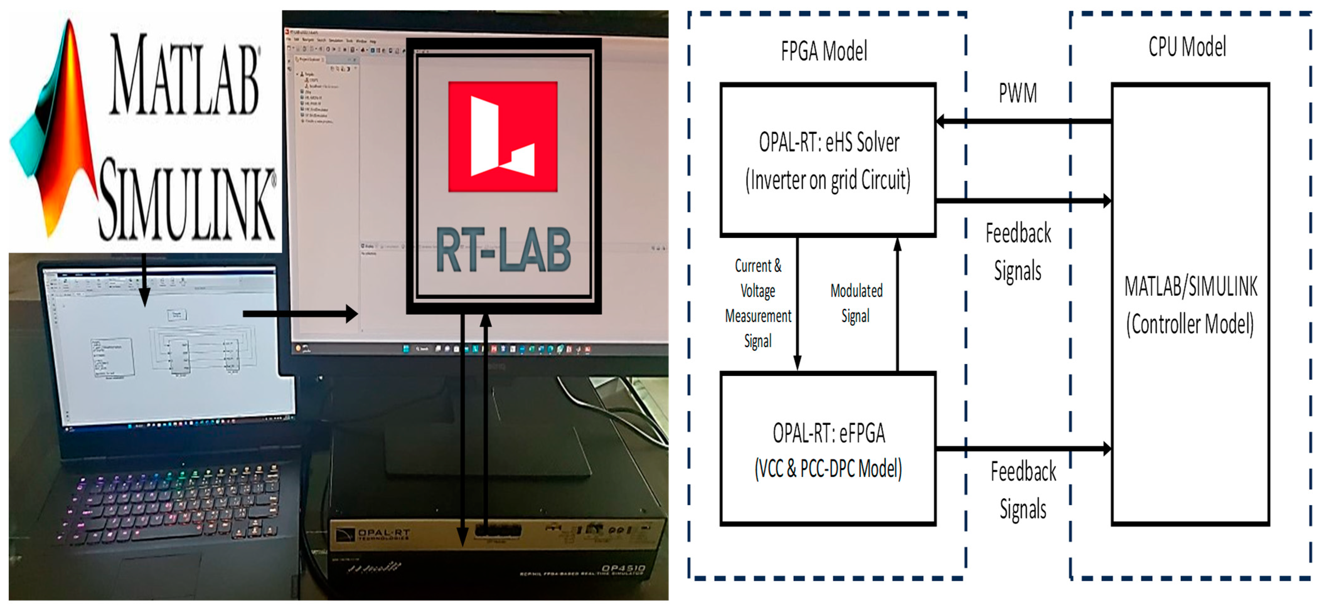
We validated the performance of PCC-DPC by implementing it in Simulink (MATLAB) and compiling it in Opal-RT as shown in Figure 2. Moreover, we used Simulink to develop the controller of VSC. Next, we evaluated PCC-DPC performance by assessing its steady-state and transient values against our previous work in [27]. The results show that PCC-DPC performs better than the controller in [27]. Table 2 presents the list of system parameters employed during the simulation experiments. This case evaluates the performance of the proposed method (PCC-DPC) against VCC-dq in [27] in a solid DC source (250 Vdc), which can be any renewable energy source, to further investigate the feasibility, transient, and steady-state of the VSC without an external effect (e.g., dynamics of PV and the grid) to the system.
Case_1: Tracking performance of active and reactive powers (Transient Mode)
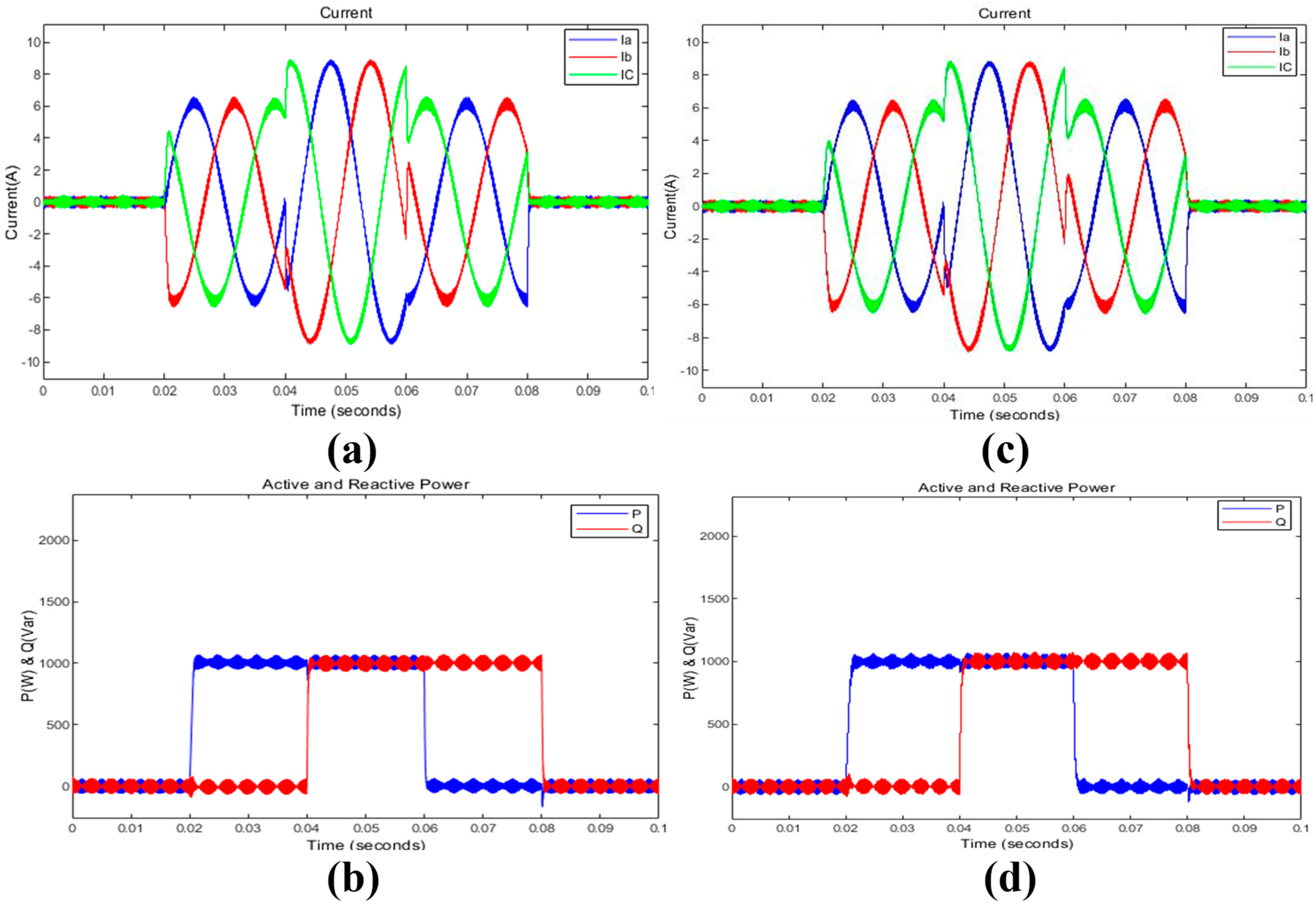
P and Q are shown in Figure 3 as functions of time. Pref reaches its maximum value of one kilowatt at t = 0.02 s before decreasing back to zero by t = 0.06 s. Qref does likewise, mounting up to one KVAR by t = 0.04 s and fading away until it disappears at t = 0.08 s.
Comparing the tracking performance of P and Q between the PCC-DPC and VCC-dq frame, it is obvious that both P and Q ripples are greatly reduced by PCC-DPC. Furthermore, PCC-DPC tracks Pref as well as Qref much better than the VCC-dq frame with less overshoot in its case. Finally, the output current ripple was significantly reduced using this method as shown in Figure 3c,d.
Case_2: Harmonics Analysis in a Steady-State Performance
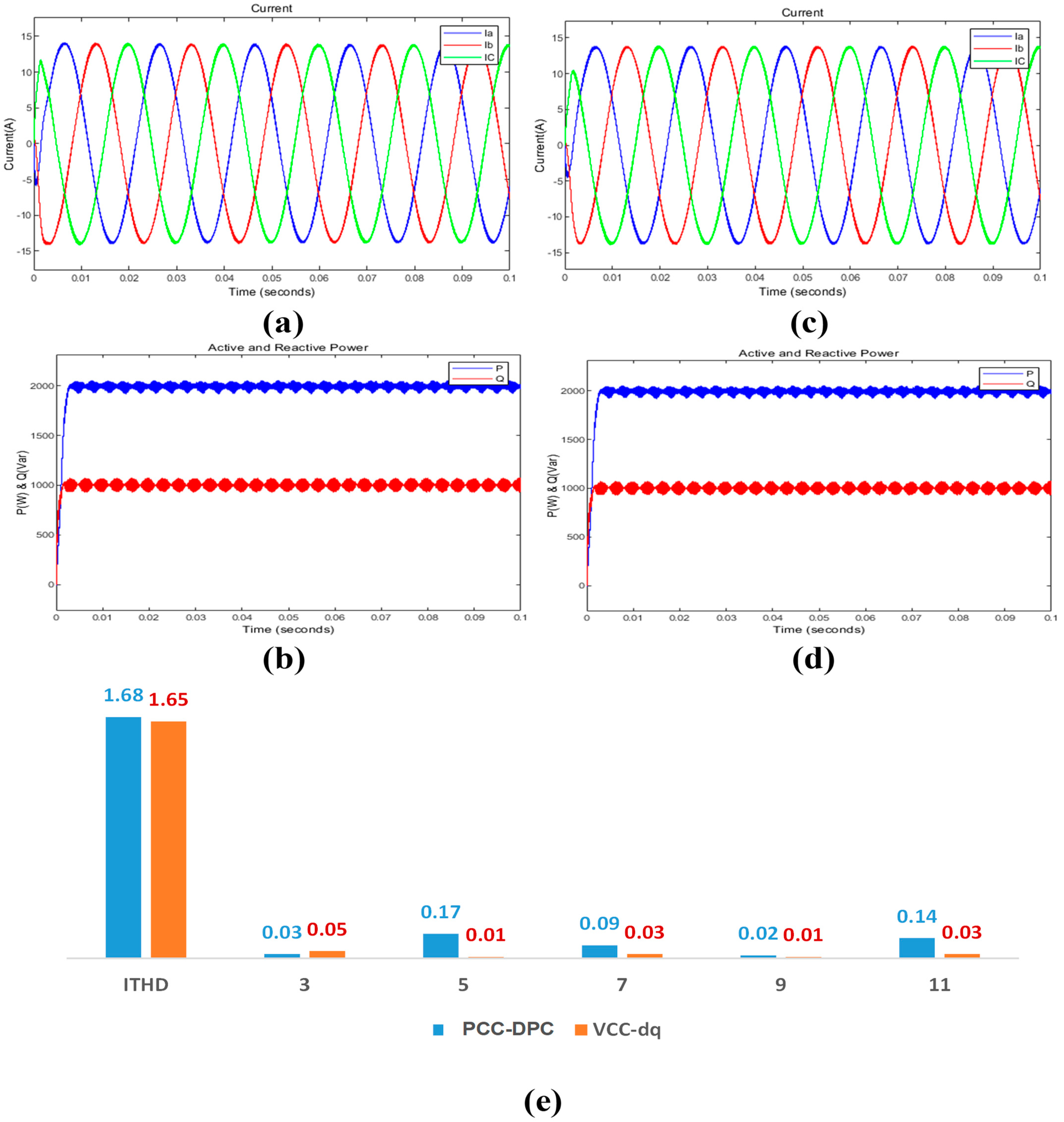
However, globally exponentially stable decoupled LTI error dynamics were obtained using our approach, which is consistent with the VCC-dq frame technique. Therefore, Figure 3b indicates that the load is drawing an active power of 2 kW while supplying a reactive power of 1 kVAR.
Harmonic indexes were compared against those produced by outputs for this approach from the third through eleventh harmonics as depicted on the graph from Figure 4e. PCC-DPC has a Total Harmonic Distortion (THD) of only about 1.68%, which is well below the typically acceptable 5% limit for grid connection purposes [29]. This value is similar to the one reached by PLL VCC-dq at THD 1.65%. This proposed PCC-DPC as VCC-dq enhances the harmonic spectrum as well as maintains its transient response on the current output side. For instance, there are slight increases in the harmonics of five, seven, and eleven. However, this needs further investigation. Finally, this minimal change is still within acceptable limits.
Case_3: Robustness Performance of a low-voltage ride-through performance
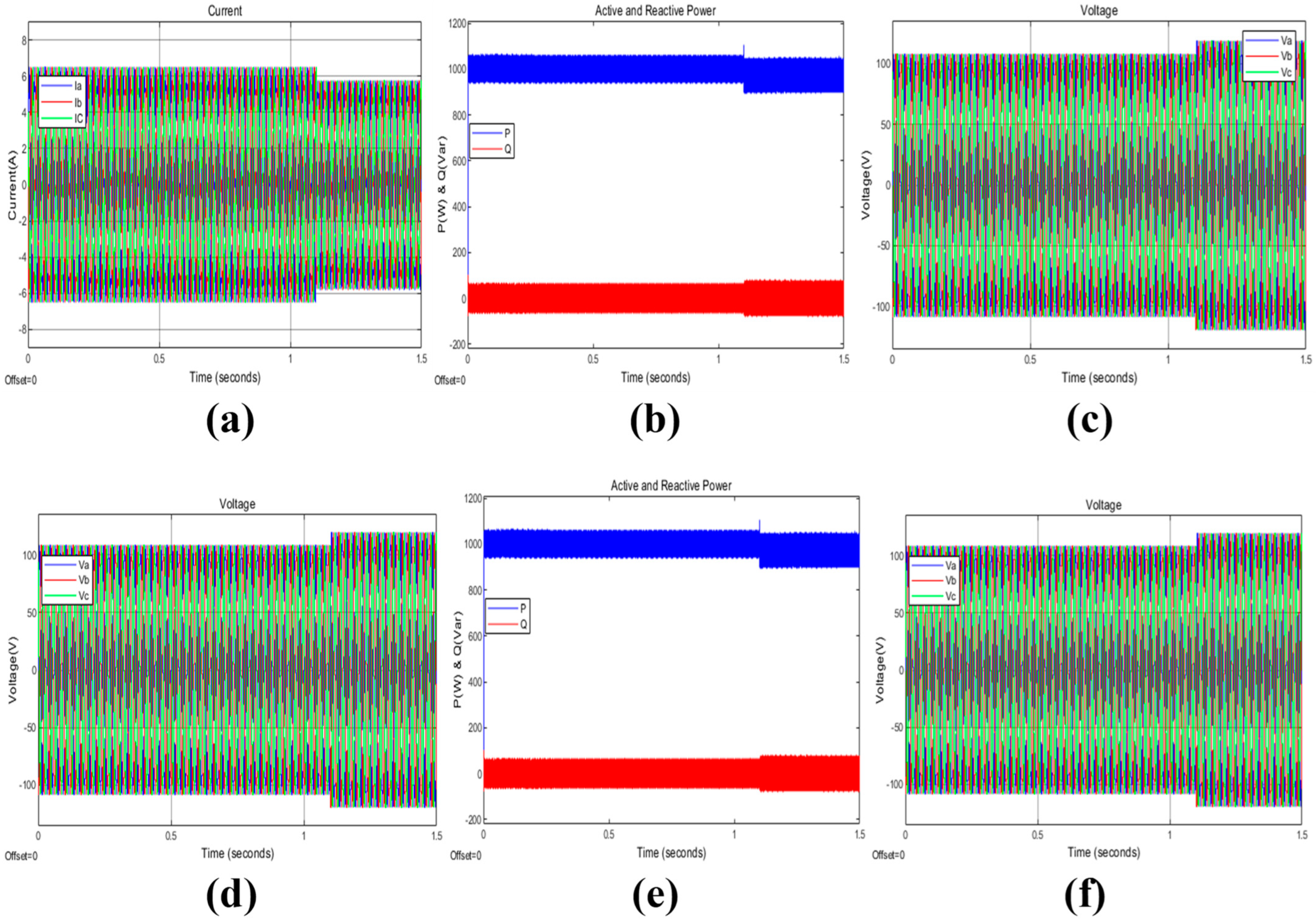
To establish the robustness of the proposed control approach, Figure 5 gives a low-voltage ride-through performance characteristic. When 1 kW was injected into the grid simulator and maintained zero var, a sudden voltage sag of 10% occurred at t = 1.1 s. In the event of a sag occurring in the grid, both PCC-DPC and VCC-dq behave identically. In order to maintain the power reference level, current must be raised up enough to counterbalance the voltage fall. The active power overshoot for both PCC-DPC and VCC-dq is below 10 percent; it converges to one kilowatt eventually. Moreover, there is not any overshoot in zero reactive power regulation by them.
Case_4: Robustness Performance of a high-voltage ride-through performance
Figure 6 demonstrates the high-voltage ride-through (HVRT) performance of the proposed control scheme in order to establish its robustness. At 1.1 s, the system injected 1 kW of active power into the grid simulator, resulting in a sudden rise of 10% in voltage. There was not any regulation on reactive power, which remained at zero var. It can be observed that both VCC-dq and PCC-DPC exhibit similar behavior when a sag occurs on the AC grid. On increasing the voltage, the current decreases to ensure power tracking is maintained. Active power for both PCC-DPC and VCC-dq has a slight overshoot of about less than 10% and converges to 1 kW while reactive power is regulated at zero without any overshoot.
Case_5: Robustness Performance property to the grid frequency
The robustness of the grid frequency is checked by testing it. The active power was fixed at 1 KW whereas reactive power = zero var as shown in Figure 6b,f with a sudden drop in grid frequency from 50 Hz to 49.8 Hz made by the grid simulator. This means that changes in frequency deviation have no effect on P and Q, as well as output currents as depicted by Figure 7a,c,d,f. As such we could infer that this form of PCC-DPC has great firmness.
Case_6: Robustness Performance under an Unbalanced Grid (a 30% voltage sag in the phase A)
Initially, a comparison between the proposed technique and VCC-dq took place under an unbalanced grid voltage condition. In addition, there was a decrease of twenty percent in voltage within phase A of the electricity network as shown in Figure 8c,f. Moreover, Figure 8a,d indicate that the situation of an imbalanced grid voltage affected the grid current. As the result of this change, the THD of the current increased by 7.81%. Active and reactive powers are effectively regulated to match the desired values as can be seen from Figure 8b,e. VCC-dq exhibits better results than PCC-DPC with the exception of the total current distortion criterion shown in Figure 9.
Case_7: Robustness Performance under an Unbalanced Grid (a 30% voltage swell in the phase A)
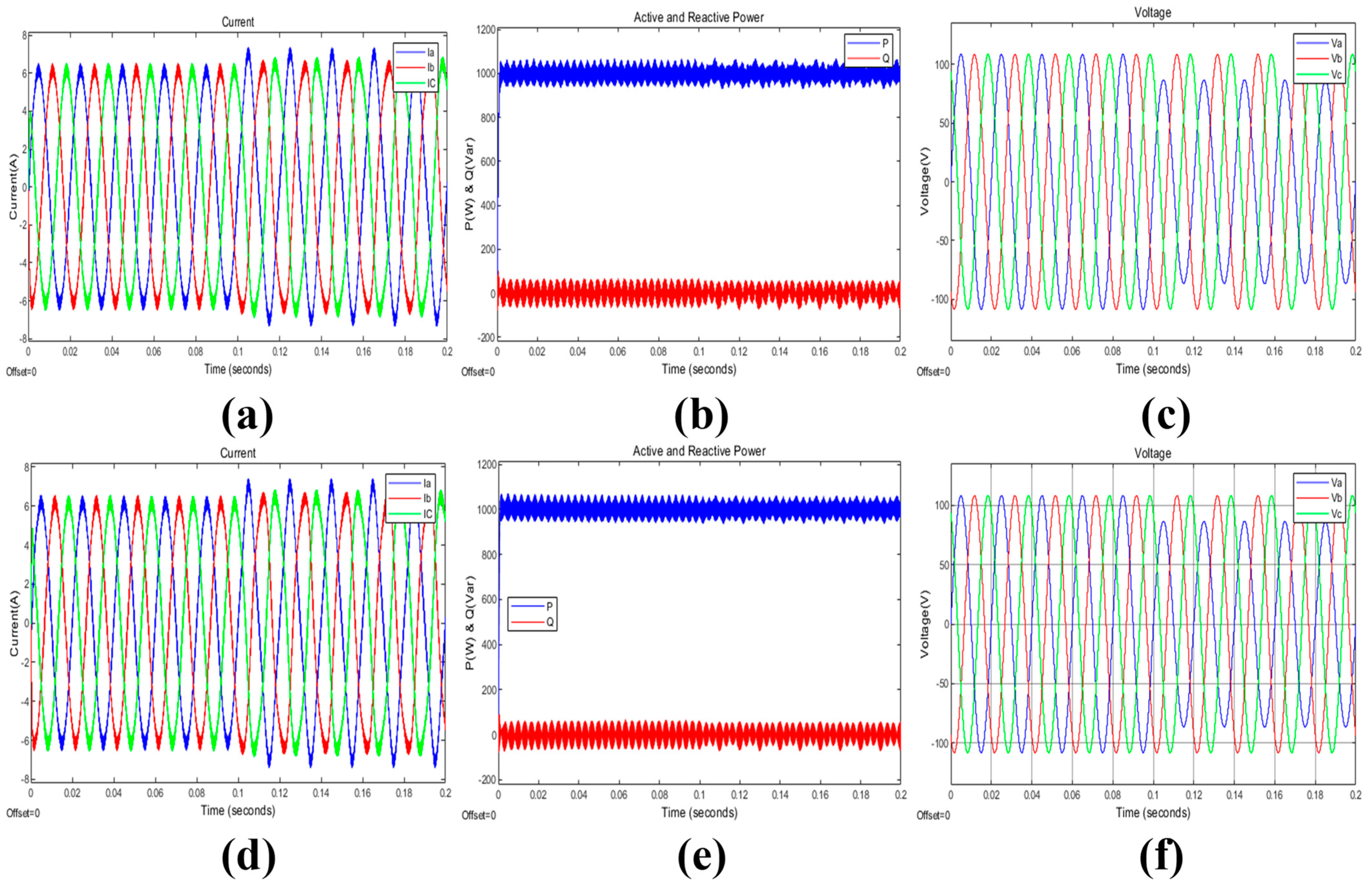
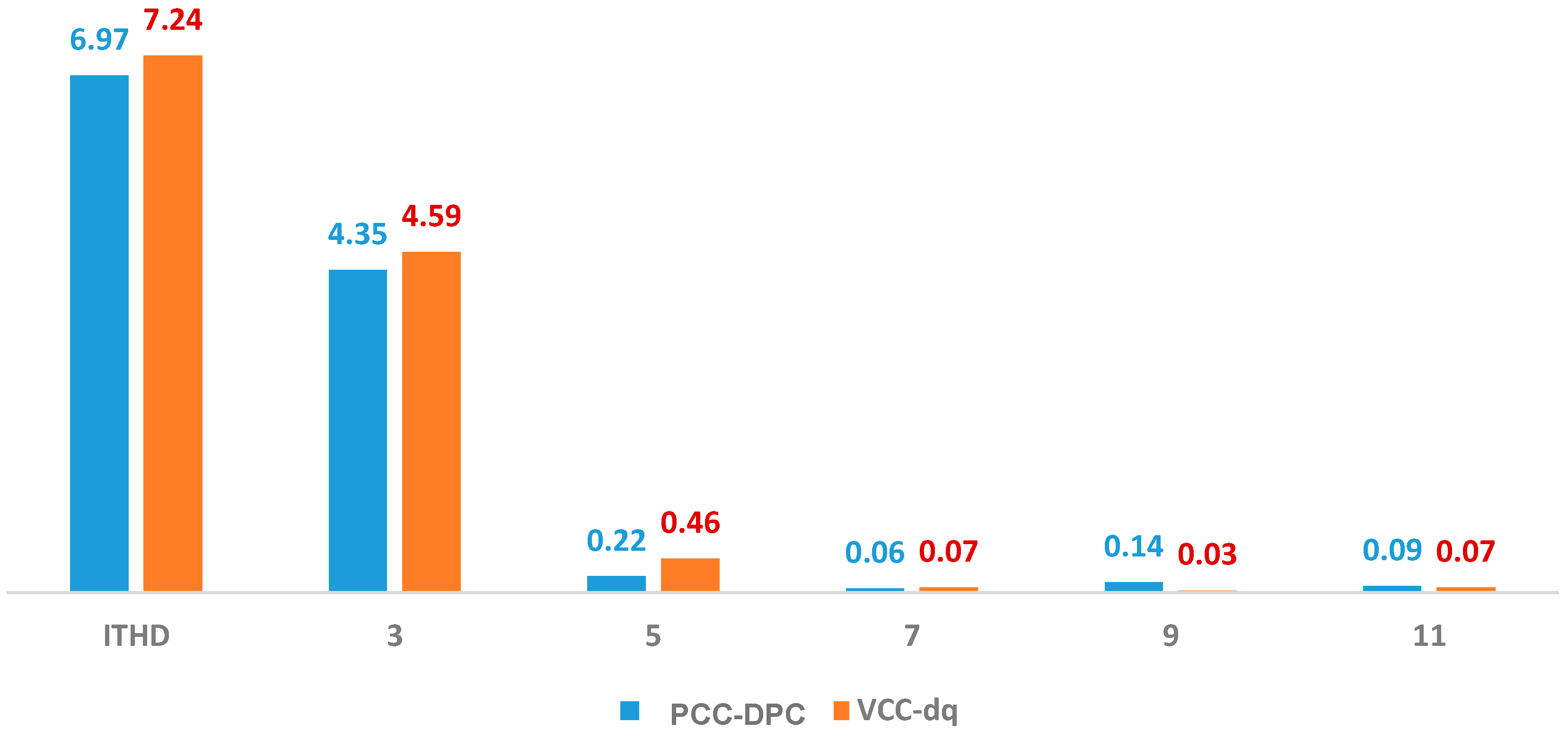
Initially, the performance of the proposed VCC-dq was evaluated for an unbalanced grid voltage case. Therefore, a twenty percent increase existed within phase A of the grid, which is shown in Figure 10c,f. Nevertheless, Figure 10a,d show that state of imbalanced grid voltage influence on grid current. This resulted in a 6.97% rise in Total Harmonic Distortion (THD) of the current. Without any power compensation, P and Q are effectively controlled to meet their objectives as shown by Figure 10b,e. The best performance is achieved by PCC-DPC as compared to VCC-dq, although it does not fulfill criteria for total current distortion as illustrated in Figure 11.

4. Discussion

Table 3 presents a concise overview of the main results obtained from the case studies that assessed the effectiveness of the proposed PCC-DPC approach in comparison to a Vector Current Controller (VCC-dq frame). These case studies illustrate that PCC-DPC has promising outcomes in terms of the following:
  • Enhanced tracking performance: accelerated reaction and potentially enhanced stability in comparison to VCC-dq.
  • Minimized steady-state harmonics: it demonstrates excellent harmonic performance in accordance with grid standards (comparable to VCC-dq), while additional research is needed to address specific harmonics.
  • Grid resilience: it ensures stable functioning and power control even in the presence of voltage drops and increases, and slight fluctuations in frequency.
Nevertheless, it is reported that from the analysis, PCC-DPC exhibits elevated current Total Harmonic Distortion (THD) when subjected to unbalanced grid conditions, necessitating additional advancements to comply with current distortion requirements set by the grid.
Table 4 illustrates that both PCC-DPC and VCC-dq are effective in tracking reference signals and attenuating harmonic distortion. However, in some situations, the optimal controller was PCC-DPC, which minimized settling periods while increasing the oscillatory transient where the overshoot and undershoot were greater. Furthermore, VCC-dq showed a more stable transient response with fewer overshoot and undershoot transients.

5. Conclusions

This paper suggests a new control method named PCC-DPC, which enhances the performance of grid-tied VSC by directly regulating instantaneous P and Q. PCC-DPC has been able to rapidly track both immediate active and reactive powers as well as improve on its steady-state capabilities. This technique was simulated using MATLAB/Simulink and Opal-RT. Simulation results showed that this strategy successfully reduced fluctuations in both active and reactive power compared to VCC-dq. This research included the following investigations: P and Q power transients monitoring; harmonic analysis for steady-state performance evaluation; and case studies on abnormal grid situations due to VSC connections. There were evaluations performed for the robustness of LVRT capability and HVRT capability. Grid frequency is a measure that indicates how well the system can respond to difficult situations. The research aimed to assess whether this technique is useful in dealing with unbalanced grid conditions such as when voltage on phase A goes down by 20%. Future studies will investigate further areas where low-switching frequency systems can be applied in imbalanced system designs and investigate the impact that network impedance may have on the control strategies provided. This investigation will next examine the network with non-zero impedance for a more realistic validation.

Author Contributions

Conceptualization, Y.A.A., A.A.A. and S.M.A.; methodology, Y.A.A., A.A.A. and S.M.A.; software, Y.A.A. and A.A.A.; validation, S.M.A. and A.A.A.; formal analysis, M.R.; investigation, Y.A.A. and A.A.A.; resources, A.A.A. and M.R.; data curation, M.R. and Y.A.A.; writing—original draft preparation, Y.A.A. and A.A.A.; writing—review and editing, M.R.; visualization, S.M.A.; supervision, S.M.A. and M.R.; project administration, M.R.; funding acquisition, M.R. and A.A.A. All authors have read and agreed to the published version of the manuscript.

Funding

This research was funded by the K. A. CARE-King Abdulaziz University Collaboration Program.

Institutional Review Board Statement

Not applicable.

Informed Consent Statement

Informed consent was obtained from all subjects involved in the study.

Data Availability Statement

The original contributions presented in the study are included in the article, further inquiries can be directed to the corresponding author.

Acknowledgments

The authors acknowledge support provided by King Abdullah City for Atomic and Renewable Energy (K. A. CARE) under the K. A. CARE-King Abdulaziz University Collaboration Program.

Conflicts of Interest

The authors declare no conflicts of interest. The funders had no role in the design of the study; in the collection, analyses, or interpretation of data; in the writing of the manuscript; or in the decision to publish the results.

Nomenclature

d-qdq-frame (rotating reference frame)
DPCDirect Power Control
fGrid Voltage Frequency
GVM-DPCVoltage Modulation Direct Power Control
LTILinear Time-Invariant
LUTLook-up Table
MGMicrogrid
MIMOMulti input Multi Output
MPC-DPCModel Predictive Control Direct Power Control
PCCPoint of Common Coupling
PCC-DPCPoint of Common Coupling Modulation of Direct Power Control
α β α β —frame (saturation reference frame)
PLLPhase-locked loop
PWMPulse width modulation
PBC-DPCPredictive Direct Power Control
SMC-DPCSliding Mode Direct Power Control
SVMSpace vector modulation
THDTotal harmonic distortion
VCCVector Current Controller
VdcDC source voltage
VSIVoltage Source Inverter
VSCVoltage Source Converter
ωGrid Voltage Angular Frequency

References

  1. Jia, J.; Yang, G.; Nielsen, A.H. A Review on Grid-Connected Converter Control for Short-Circuit Power Provision under Grid Unbalanced Faults. IEEE Trans. Power Deliv. 2018, 33, 649–661. [Google Scholar] [CrossRef]
  2. Wei, B.; Gui, Y.; Trujillo, S.; Guerrero, J.M.; Vasquez, J.C.; Marzabal, A. Distributed Average Integral Secondary Control for Modular UPS Systems-Based Microgrids. IEEE Trans. Power Electron. 2019, 34, 6922–6936. [Google Scholar] [CrossRef]
  3. Wang, X.; Blaabjerg, F.; Liserre, M.; Chen, Z.; He, J.; Li, Y. An active damper for stabilizing power electronics-based AC systems. In Proceedings of the 2013 Twenty-Eighth Annual IEEE Applied Power Electronics Conference and Exposition (APEC), Long Beach, CA, USA, 17–21 March 2013; pp. 1131–1138. [Google Scholar] [CrossRef]
  4. Kazmierkowski, M.; Malesani, L. Current control techniques for three-phase voltage-source PWM converters: A survey. IEEE Trans. Ind. Electron. 1998, 45, 691–703. [Google Scholar] [CrossRef]
  5. Reyes, M.; Rodriguez, P.; Vazquez, S.; Luna, A.; Teodorescu, R.; Carrasco, J.M. Enhanced decoupled double synchronous reference frame current controller for unbalanced grid-voltage conditions. IEEE Trans. Power Electron. 2012, 27, 3934–3943. [Google Scholar] [CrossRef]
  6. Diaz, N.L.; Luna, A.C.; Vasquez, J.C.; Guerrero, J.M. Centralized Control Architecture for Coordination of Distributed Renewable Generation and Energy Storage in Islanded AC Microgrids. IEEE Trans. Power Electron. 2017, 32, 5202–5213. [Google Scholar] [CrossRef]
  7. Mortezaei, A.; Simoes, M.; Savaghebi, M.; Guerrero, J.; Al-Durra, A. Cooperative control of multi-master-slave islanded microgrid with power quality enhancement based on conservative power theory. In Proceedings of the 2017 IEEE Power & Energy Society General Meeting, Chicago, IL, USA, 16–20 July 2017. [Google Scholar] [CrossRef]
  8. Arcos-Aviles, D.; Pascual, J.; Guinjoan, F.; Marroyo, L.; Sanchis, P.; Marietta, M.P. Low complexity energy management strategy for grid profile smoothing of a residential grid-connected microgrid using generation and demand forecasting. Appl. Energy 2017, 205, 69–84. [Google Scholar] [CrossRef]
  9. Mensou, S.; Essadki, A.; Nasser, T.; Idrissi, B.B. A direct power control of a DFIG based-WECS during symmetrical voltage dips. Prot. Control. Mod. Power Syst. 2020, 5, 5. [Google Scholar] [CrossRef]
  10. Boubzizi, S.; Abid, H.; El Hajjaji, A.; Chaabane, M. Comparative study of three types of controllers for DFIG in wind energy conversion system. Prot. Control. Mod. Power Syst. 2018, 3, 21. [Google Scholar] [CrossRef]
  11. Zhang, Y.; Qu, C. Direct power control of a pulse width modulation rectifier using space vector modulation under unbalanced grid voltages. IEEE Trans. Power Electron. 2015, 30, 5892–5901. [Google Scholar] [CrossRef]
  12. Noguchi, T.; Tomiki, H.; Kondo, S.; Takahashi, I. Direct power control of PWM converter without power-source voltage sensors. IEEE Trans. Ind. Appl. 1998, 34, 473–479. [Google Scholar] [CrossRef]
  13. Bouafia, J.G.; Krim, F. Predictive direct power control of three-phase pulse width modulation (PWM) rectifier using space-vector modulation (SVM). IEEE Trans. Power Electron. 2010, 25, 228–236. [Google Scholar] [CrossRef]
  14. Cheng, P.; Nian, H. Direct power control of voltage source inverter in a virtual synchronous reference frame during frequency variation and network unbalance. IET Power Electron. 2016, 9, 502–511. [Google Scholar] [CrossRef]
  15. Li, L.; Nian, H.; Ding, L.; Zhou, B. Direct power control of dfig system without phase-locked loop under unbalanced and harmonically distorted voltage. IEEE Trans. Energy Convers. 2018, 33, 395–405. [Google Scholar] [CrossRef]
  16. Nian, H.; Li, L. Direct power control of doubly fed induction generator without phase-locked loop under harmonically distorted voltage conditions. IEEE Trans. Power Electron. 2018, 33, 5836–5846. [Google Scholar] [CrossRef]
  17. Antoniewicz, P.; Kazmierkowski, M.P. Virtual-flux-based predictive direct power control of ac/dc converters with online inductance estimation. IEEE Trans. Ind. Electron. 2008, 55, 4381–4390. [Google Scholar] [CrossRef]
  18. Vazquez, S.; Marquez, A.; Aguilera, R.; Quevedo, D.; Leon, J.I.; Franquelo, L.G. Predictive optimal switching sequence direct power control for grid-connected power converters. IEEE Trans. Ind. Electron. 2014, 62, 2010–2020. [Google Scholar] [CrossRef]
  19. Choi, D.-K.; Lee, K.-B. Dynamic performance improvement of AC/DC converter using model predictive direct power control with finite control set. IEEE Trans. Ind. Electron. 2014, 62, 757–767. [Google Scholar] [CrossRef]
  20. Hu, J. Improved Dead-Beat Predictive DPC Strategy of Grid-Connected DC–AC Converters with Switching Loss Minimization and Delay Compensations. IEEE Trans. Ind. Inform. 2013, 9, 728–738. [Google Scholar] [CrossRef]
  21. Hu, J.; Zhu, Z.Q. Improved voltage-vector sequences on dead-beat predictive direct power control of reversible three-phase grid-connected voltage-source converters. IEEE Trans. Power Electron. 2013, 28, 254–267. [Google Scholar] [CrossRef]
  22. Gui, Y.; Kim, C.; Chung, C.C.; Guerrero, J.M.; Guan, Y.; Vasquez, J.C. Improved direct power control for grid-connected voltage source converters. IEEE Trans. Ind. Electron. 2018, 65, 8041–8051. [Google Scholar] [CrossRef]
  23. Gui, Y.; Wang, X.; Blaabjerg, F. Vector Current Control Derived from Direct Power Control for Grid-Connected Inverters. IEEE Trans. Power Electron. 2019, 34, 9224–9235. [Google Scholar] [CrossRef]
  24. Gui, Y.; Wang, X.; Blaabjerg, F.; Pan, D.; Gui, Y.; Wang, X.; Blaabjerg, F.; Pan, D.; Gui, Y.; Wang, X.; et al. Control of Grid-Connected Voltage-Source Converters: The Relationship between Direct-Power Control and Vector-Current Control. IEEE Ind. Electron. Mag. 2019, 13, 31–40. [Google Scholar] [CrossRef]
  25. Gui, Y.; Wei, B.; Li, M.; Guerrero, J.M.; Vasquez, J.C. Passivity-based coordinated control for islanded AC microgrid. Appl. Energy 2018, 229, 551–561. [Google Scholar] [CrossRef]
  26. Gui, Y.; Wang, X.; Wu, H.; Blaabjerg, F. Voltage-Modulated Direct Power Control for a Weak Grid-Connected Voltage Source Inverters. IEEE Trans. Power Electron. 2019, 34, 11383–11395. [Google Scholar] [CrossRef]
  27. Almatani, N.O.; Alhussainy, A.A.; Alghamdi, S.; Kotb, H.; AboRas, K.M.; Vellingiri, M.; Rawa, M. Assessment of a High-Order Stationary Frame Controller for Two-Level and Three-Level NPC Grid-Connected Inverters. Energies 2022, 15, 9313. [Google Scholar] [CrossRef]
  28. Ahmad, S.; Rashid, T.; Ferdowsy, C.S.; Islam, S.; Mahmood, A.H. A technical comparison among different PV-MPPT algorithms to observe the effect of fast changing solar irradiation. In Proceedings of the 2015 IEEE International WIE Conference on Electrical and Computer Engineering (WIECON-ECE), Dhaka, Bangladesh, 19–20 December 2015; pp. 155–158. [Google Scholar]
  29. Pan, D.; Ruan, X.; Wang, X.; Yu, H.; Xing, Z. Analysis and Design of Current Control Schemes for LCL-Type Grid-Connected Inverter Based on a General Mathematical Model. IEEE Trans. Power Electron. 2017, 32, 4395–4410. [Google Scholar] [CrossRef]
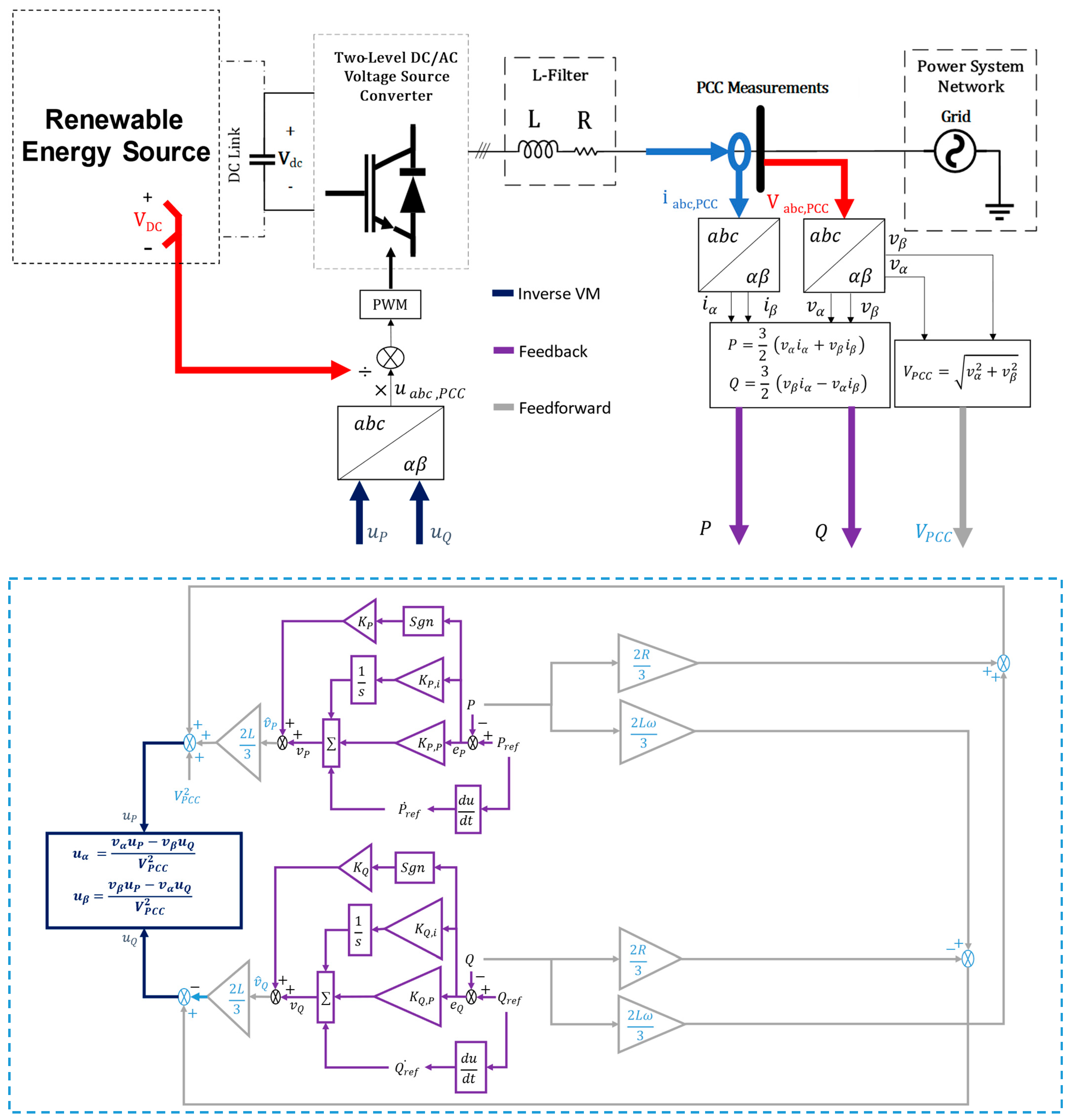
Figure 1. The controller’s block diagram showing the proposed PCC-DPC.
Energies 17 05111 g001
Figure 2. Experimental validation set-up.
Energies 17 05111 g002
Figure 3. Transient mode with a solid DC source. (a) Output current at PCC, the VCC-dq [27]; (b) P and Q at PCC, the VCC-dq [27]; (c) output current at PCC, the PCC-DPC; and (d) P and Q at PCC, the PCC-DPC.
Energies 17 05111 g003
Figure 4. Steady-tate with a solid DC source. (a) Output current at PCC, the VCC-dq [27]; (b) P and Q at PCC, the VCC-dq [27]; (c) output current at PCC, the PCC-DPC; (d) P and Q at PCC, the PCC-DPC; and (e) a comparison of current harmonic contents with the PCC-DPC and VCC-dq methods.
Energies 17 05111 g004
Figure 5. Low-voltage ride-through performance. (a) Output current at PCC, the VCC-dq [27]; (b) P and Q at PCC, the VCC-dq [27]; (c) output voltage at PCC, the VCC-dq [27]; (d) output current at PCC, the PCC-DPC; (e) P and Q at PCC, the PCC-DPC; and (f) output voltage at PCC, the PCC-DPC [27].
Energies 17 05111 g005
Figure 6. High-voltage ride-through performance. (a) Output current at PCC, the VCC-dq [27]; (b) P and Q at PCC, the VCC-dq [27]; (c) output voltage at PCC, the VCC-dq [27]; (d) output current at PCC, the PCC-DPC; (e) P and Q at PCC, the PCC-DPC; and (f) output voltage at PCC, the PCC-DPC [27].
Energies 17 05111 g006
Figure 7. The grid frequency changed from 50 Hz to 49.8 Hz at 0.4 s with 1 kW and 0 var. (a) Output current at PCC, the VCC-dq [27]; (b) P and Q at PCC, the VCC-dq [27]; (c) output voltage at PCC, the VCC-dq [27]; (d) output current at PCC, the PCC-DPC; (e) P and Q at PCC, the PCC-DPC; and (f) output voltage at PCC, the PCC-DPC [27].
Energies 17 05111 g007
Figure 8. Unbalanced grid (a 20% voltage sag in phase A). (a) Output current at PCC, the VCC-dq [27]; (b) P and Q at PCC, the VCC-dq [27]; (c) output voltage at PCC, the VCC-dq [27]; (d) output current at PCC, the PCC-DPC; (e) P and Q at PCC, the PCC-DPC; and (f) output voltage at PCC, the PCC-DPC.
Energies 17 05111 g008
Figure 9. A comparison of current harmonic contents with the PCC-DPC and VCC-dq methods for Unbalanced grid a 20% Voltage sag in Phase A.
Energies 17 05111 g009
Figure 10. Unbalanced grid (a 20% voltage swell in phase A). (a) Output current at PCC, the VCC-dq [27]; (b) P and Q at PCC, the VCC-dq [27]; (c) output voltage at PCC, the VCC-dq [27]; (d) output current at PCC, the PCC-DPC; (e) P and Q at PCC, the PCC-DPC; and (f) output voltage at PCC, the PCC-DPC [27].
Energies 17 05111 g010
Figure 11. A comparison of current harmonic contents with the PCC-DPC and VCC-dq methods for Unbalanced grid a 20% Voltage swell in Phase A.
Energies 17 05111 g011
Table 1. Comparison between VCC and DPC.
FeatureVector Control (VCC)Direct Power Control (DPC)Grid Voltage Modulation DPC (GVM-DPC)
Control MethodIndirect control of real and reactive power through d–q transformationDirect control of real and reactive powerDirect control of grid voltage
Grid Synchronization PLLRequiredNot requiredNot required
Power QualityIntroduce current harmonics due to complex calculations and require additional filtering to meet grid standardsPotential for high Total Harmonic Distortion (THD) due to variable switching frequencyAims to reduce harmonic distortion by directly controlling grid voltage
Transient ResponseSlower response due to indirect controlFaster response due to Direct Power ControlCan achieve fast transient response
Steady-State PerformanceGenerally good steady-state performancePotential for power fluctuations due to variable switching frequency Aims for improved steady-state performance by minimizing voltage variations
Computational BurdenModerateCan be high due to complex calculations and potential need for online calculations (predictive DPC)Lower compared to DPC due to simpler structure
RobustnessGenerally robustLess robust due to unpredictable harmonic spectrumConsidered more robust compared to other DPC methods (SMC-DPC, PBC-DPC)
VariationsSeveral improved VCC approaches with additional PI regulatorsPredictive DPC, Model Predictive Control DPC (MPC-DPC), virtual synchronous reference frame DPC-
Recent DevelopmentsFocus on improving robustness and stabilityFocus on reducing harmonic distortion, fixed switching frequency-
Table 2. System parameters used in simulation and experiment.
ParameterValue
DC/AC voltage source converter
Line to line voltage (rms)133 V
Resistance filter (Ra,b,c)0.16 Ω
Inductive filter (La,b,c)4 mH
AC frequency50 Hz
Switching frequency10 kHz
Sampling frequency10 kHz
Power rate2 kVA
Vector   Current   control   in   d q controller frame
Proportional   gain   k p 40
Integral   gain   k i 1608.8
PLL - Proportional   gain   k p 10
PLL - Integral   gain   k i 50,000
Voltage-Modulated Direct Power Control
Integral   gain   K P , i , K P , i 5000
Proportional   gain   K Q , P , K Q , P 300
Proportional   gain   K P , K Q 10
Table 3. Analysis of PCC-DPC performance against VCC—case studies.
Case StudyFocusPCC-DPC PerformanceVCC-dq Frame PerformanceKey Observations
Tracking Performance (Transient Mode)Ability to track active and reactive power referencesSignificantly reduced ripples in active and reactive power, faster tracking of active power, and smaller overshoot in reactive powerSimilar performance with reduced ripplesPCC-DPC offers faster response and potentially better stability
Harmonics Analysis (Steady-State)Harmonic content in output currentsTHD (total harmonic distortion) of 1.68% (within grid standards)—slight increase in fifth, seventh, and eleventh harmonics (needs further investigation)THD of 1.65%PCC-DPC achieves good harmonic performance similar to VCC-dq but requires further investigation for specific harmonics
Low-Voltage Ride-Through (LVRT)Response to voltage sagsMaintains power reference with small overshoot in active power—regulates reactive power without overshootSimilar behavior with small overshoot in active powerBoth methods demonstrate robustness during voltage sags
High-Voltage Ride-Through (HVRT)Response to voltage swellsMaintains power reference with small overshoot in active power—regulates reactive power without overshootSimilar behavior with small overshoot in active powerBoth methods demonstrate robustness during voltage swells
Grid Frequency VariationResponse to minor frequency changesNo impact on active or reactive power, or output currentsSimilar behaviorBoth methods demonstrate robustness to minor grid frequency variations
Unbalanced Grid (20% Sag in Phase A)Performance under unbalanced voltageMaintains power reference without compensation—increased current THD (7.81%)Better performance in power regulation and violated current THD standardPCC-DPC prioritizes power regulation but needs improvement for THD under unbalanced conditions
Unbalanced Grid (20% Swell in Phase A)Performance under unbalanced voltageMaintains power reference without compensation—increased current THD (6.97%)Better performance in power regulation and violated current THD standardSimilar to case 6, PCC-DPC prioritizes power regulation but needs improvement for THD under unbalanced conditions
Table 4. Steady-state and transient performance metrics for active power.
Performance EvaluationCase StudyRise TimeSettling TimeSettling Min/MaxOver/UndershootPeakPeak Time
PCC-DPCTracking Performance (Transient Mode)2.9247 × 10−70.1000−128.5664/1.0672 × 10+31.0155 × 10+4/8.5122 × 10+41.0672 × 10+30.0314
Harmonics Analysis (Steady-State)0.00180.09891.7627 × 10+3/2.0580 × 10+33.1665/0.33772.0580 × 10+30.0077
VCC-dqTracking Performance (Transient Mode)5.7426 × 10−70.1000−168.7826/1.0741 × 10+36.8514 × 10+3/4.4237 × 10+41.0741 × 10+30.0315
Harmonics Analysis (Steady-State)0.00130.09921.8081 × 10+3/2.1117 × 10+35.1031/0.00172.1117 × 10+30.0047
Disclaimer/Publisher’s Note: The statements, opinions and data contained in all publications are solely those of the individual author(s) and contributor(s) and not of MDPI and/or the editor(s). MDPI and/or the editor(s) disclaim responsibility for any injury to people or property resulting from any ideas, methods, instructions or products referred to in the content.