Article

The Problem of Power Variations in Wind Turbines Operating under Variable Wind Speeds over Time and the Need for Wind Energy Storage Systems

by
Cristian Paul Chioncel
1,
Elisabeta Spunei
1,* and
Gelu-Ovidiu Tirian
2
1
Department of Engineering Sciences, Faculty of Engineering, Babes-Bolyai University, 400028 Cluj-Napoca, Romania
2
Faculty of Engineering Hunedoara, Polytechnic University of Timisoara, 300006 Timisoara, Romania
*
Author to whom correspondence should be addressed.
Energies 2024, 17(20), 5079; https://doi.org/10.3390/en17205079
Submission received: 13 September 2024 / Revised: 30 September 2024 / Accepted: 9 October 2024 / Published: 12 October 2024
(This article belongs to the Special Issue Optimal Control of Wind and Wave Energy Converters)

Abstract

:
One of the most important and efficient sources of green electricity is catching air currents through wind turbine technology. Wind power plants are located in areas where the energy potential of the wind is high but it varies. The time variation of the wind generates fluctuations in the power produced by the wind farms that is injected into the grid. This elevates, depending on the intensity, problems of network stability and the need for balancing energy, thus raising both technical and cost issues. The present paper analyzes the behavior of a wind turbine (WT) over time in varying wind speed conditions, highlighting that without automation algorithms, a WT is far from the operation at the maximum power point (MPP). However, even when it is brought to operate at MPP, there are still significant variations in the power injected into the network. These power variations can be compensated if the wind system has energy storage facilities for the captured wind. All of these assumptions are analyzed using improved mathematical models and processed in simulations, with experimental data used as input from a wind turbine with an installed power of 2.5 [MW] in operation on the Romanian Black Sea coastal area. Consequently, the paper demonstrates that during an operation in the optimal area, from an energy perspective, the wind turbine’s maximum power point requires a storage system for the captured wind energy.

1. Introduction

Regarding the energy crisis and socio-economic development correlated with climate change, as well as energy security in a geopolitical context, many countries have initiated the transition from an energy system predominantly dependent on fossil fuels to a diversified and sustainable energy mix [1], with an increasing share of green energy [2].
The purpose of this paper is to analyze the necessity of installing captured wind energy storage facilities in wind systems that operate at variable wind speeds over time [3]. This will ensure that the electroenergetic system continues to operate as intended and that the wind turbine operates at its maximum power point (MPP), at the optimal mechanical angular speed (MAS), and at the optimal power point. Energy storage systems can be categorized based on their storage configuration as local, distributed, or centralized [4]. The optimal configuration of the storage systems must be carried out according to different algorithms so that they ensure the reliability of the system and contribute to the improvement of the use of energy from renewable sources within the energy system [5]. At the same time, the storage facility must be properly sized [6] so as to cover the energy gaps, as well as to minimize costs [7]. Storage pumping plants with large storage capacities are used as storage facilities [8].
In existing systems, the load on the electric generator (PEG) is adjusted based on the wind speed value [9,10] and the optimal speed’s dependency on wind speed. The actual wind speed may be different from the speed measured by the sensor on the nacelle, which is why different methods are used to determine the actual wind speed value [11]. In all cases, wind systems must operate optimally from an energy point of view at time-varying wind speeds [12,13]. The wind turbine (WT) must run at the optimal MAS, ωOPTIM, or the optimal rotational speed, nOPTIM, in order to accomplish a maximum capture of wind energy at a given wind speed [14,15]. Thus, the provision of auxiliary services can also be achieved by regulating the frequency [16]. Due to the significant mechanical inertia of the wind system, operating the WT at the MPP and at the MAS, ωOPTIM, is a complicated challenge at time-varying wind speeds [17]. Different control strategies are used with different types of algorithms, such as PI to control the power output [18] and optimal operation according to wind speed [19,20]. The adjustment of the electric generator’s load in accordance with the wind speed, v, is the basis for having the WT operating at the ideal mechanical angular speed and the MPP [12].
The function PWT(ω), which represents the WT power characteristic, reaches its maximum MPP at the optimum mechanical angular speed (ωOPTIM)—the reference quantity for the control system [21,22]. When operating at the MPP, the time variation of the wind speed imposes the time variation of the mechanical angular speed. At optimal energy control of the wind system, the time variation of the wind speed must be identical to the time variation of the mechanical angular velocity ω.
Thus, the problems treated in the paper consider the operation of wind turbines at the MPP at variable wind speeds over time. Major difficulties appear in wind systems operating at variable wind speeds, while the specialized literature has addressed these aspects mainly at constant wind speeds. The novelties brought about are: the wind speed being variable over time means that the MPP operating point is not fixed, and in this sense, the authors of this article analyze these aspects; the operation at the MPP is achieved by prescribing the value of the power at the electric generator, and this paper presents the fact that, at wind speeds increasing over time, the power value at the electric generator must decrease, and at wind speeds decreasing over time, the power value at the electric generator must grow.
The main sections of this paper are an overview of the main implemented storage facilities for wind power, an analysis of the wind and mechanical speeds at the generator, the MPP of the operating WT on the power curve at variable wind speeds, the determination of the mathematical model for the WT, the development of an algorithm for determining power losses, discussion, results, perspectives, and the references used.

2. Maximum Capture of Wind Energy and the Need for Its Storage

Obtaining electricity through the extensive growth of wind systems poses major obstacles for the electroenergetic system in the sense that [11]:
  • With time-varying wind speeds, the electrical power provided by wind systems in the national energy system is variable, depending on the wind speed;
  • Due to the high-value equivalent moment of inertia, J, it is necessary to adjust the power of the electric generator in order to ensure that the mechanical angular speed, ω, equals the ωOPTIM, in order to achieve an operation of the WT at the maximum power point and at time-varying wind speeds, in addition to the significantly time-varying WT power [23,24]:
ω = ωOPTIM = kV·v
At high values of the J and at significant variations in wind speed, as well as at high values of its derivative, the value of the power at the electric generator can even become negative, which requires a switch to a motor regime, in which case there are power gaps in the network.
3.
When a WT operates at its maximum power point, electric power fluctuations are produced by:
  • The power generated by WTs is directly proportional to the cube of the wind speed;
  • Inertial power, PINERTIAL, is dependent on the wind speed and its derivative:
PINERTIAL = J·(dω/dt)·ω = J·(kV)3·(dv/dt)·v
In cases where the variations in the time of the optimal rotational speeds (optimal mechanical angular speeds) are identical to the variation in the wind speed in time, a maximum wind energy will be captured.
In the utilization of wind systems, the fluctuation of the power injected into the grid is a key consideration. From the perspective of the stability of the network, it is desired that the value of the injected power be as constant as possible [25], even if the value of the wind speed varies over time, which is an apparently unsolvable contradiction. However, wind energy storage facilities can be implemented to solve this issue of wind systems.
Two significant valid storage solutions were identified in the specialized literature [26,27] of the field: storage in batteries and storage in terms of hydraulic power.
In [11], a hydraulic energy storage system is presented, which involves the use of hydro-towers and an asynchronous generator with a wound rotor. The control of the ω is accomplished by adjusting the rotor power of the generator. Consequently, the converter that connects the rotor of the generator to the pumping station operates at a low power level. The nacelle’s support pillar is constructed in the form of an upper tank, while the lower tank serves as a reservoir, a lake, or the sea with a significant capacity. The doubly fed induction generator’s rotor transfers power to the hydraulic storage system through a permanent magnet synchronous machine, functioning as a motor during pumping and as a generator when converting hydro energy into electricity. The power flow in the rotor circuit is two-way. During periods of high wind power, water is pumped from the lake water source to the hydro tower, where it stores the excess energy. When required, this stored energy is then released back into the lake or ocean.
In [10], a wind system with synchronous generator and pumped storage is presented on the Greek island of Ikaria. The hybrid power plant consists of three hydroelectric units (H1: 1.05 MW, H2-3: 2·1.55 MW) all equipped with Pelton turbines, a pumping station, 8 fixed speed pumps, and 4 variable speed pumps with a variable speed of 0.25 MW each and a 3·0.9 MW wind farm.
In small standalone systems, frequency and voltage control as well as power system stability are difficult problems at significantly time-varying wind speeds. Currently, the pumping station is controlled to track electricity production, compensating for the variations in wind power that can disrupt frequency control. The latter is provided by diesel units, which must be replaced by hydroelectric turbines if a high penetration of renewable energy sources is desired. However, this introduces significant challenges for frequency regulation due to the slow response of hydroelectric units, water column inertia, and wind turbines.
In [8], a classic model of a wind turbine and pumped storage hydropower plant is presented in Tunisia, where the wind power plant has an installed capacity of 200 MW. It is stated that a high penetration of energy from wind sources raises the problem of instability of the Tunisian energy system, caused by the intermittency and fluctuation of wind speed, which varies significantly over time. This has an impact on the frequency and voltage of the system. It should, however, be noted that by using wind energy storage facilities, these deficiencies can be eliminated.
The conducted study assesses the energy efficiency of wind power plants operating at significant time-varying wind speeds, highlighting solutions based on energy storage systems to ensure the desired outcome: high energy efficiency—performing at the MPP and ensuring electrical grid stability.
The study was carried out at time-varying wind speeds and based on the measurement of three fundamental quantities: wind speed, v, power, PEG, and MAS, ω, at the electric generator.
In order for the wind turbine to operate in the MPP at variable wind speeds over time, it is necessary to change the load on the electric generator, depending on the wind speed value [11].
Capturing maximum wind energy at time-varying wind speeds [28] in harsh weather conditions that can cause damage to the system [29,30], and in the absence of a storage system, significantly disrupts the operation of the power system [12], creating instability in the system.
Considering the problem of storing wind energy at time-varying wind speeds, it becomes necessary to operate the wind turbine at the point of maximum power and at the optimal mechanical angular velocity for the following reasons:
  • The operation of the electrical system is not affected;
  • Compensation for the fluctuations in wind energy is attained at a local or regional level;
  • The discrepancy between the need for grid power and the generation of wind power has been resolved;
  • At the local level, collaborative coordination allows for the planning of electricity distribution and expansion in isolated systems;
  • It is possible to create a flexible electricity source by harnessing short-term kinetic energy and long-term hydroelectric potential energy.
The authors incorporated the mathematical model of the WT into their simulations in Scientific WorkPlace 4.0, being confident that it accurately reflects the power output of the WT, known as the PWT(ω,v) function [31]. Different forms of the WT power characteristics PWT(ω,v) [32,33] have been documented in several sources.
The most advantageous case is determined by three parameters, specifically a, b, and c, in the following format [34]:
PWT(ω,v) = ρ·π·Rp2·Cp(λ)·v3 = a(V/ω − b)·e−c(v/ω)·v3
where: ρ—air density in the WT operating location, Rp—rotor blade radius, Cp(λ)—power conversion coefficient, λ = ω·Rp/v.
The determination of parameters a, b, and c is accomplished through the measurement of several factors, including v, PEG, and MAS at EG n/ω. By carefully measuring and analyzing these variables, the specific values for a, b, and c can be established. It is imperative to have a thorough grasp of the mathematical model of the wind turbine (MM-WT) [35], which is also dependent on its constructive characteristics [36,37], in order to effectively regulate the system and maintain the turbine’s performance at its maximum power capacity [38].
Considering the experimental data obtained from the GEWE-B2.5 series, a 2.5 MW wind turbine (WT) with a rotor diameter of 100 m is used to establish the mathematical model of the WT (MM-WT). This model takes into account an equivalent inertia moment (turbine + gearbox + generator) of J = 5372.5 kgm2 and the nominal power obtained at the generator level, which operates at a rotational speed of 1500 rpm. The WT is currently operational on the Romanian Black Sea coast [9].
The simulation uses a mathematical representation of the WT, shown in the following format:
PTV(ω,v) = 6.5086·105 (v/ω − 1.7488·10−2)·e−41.495(v/ω)·v3 [W]
The PWT(ω,v) is contingent upon the v and the ω. The maximum power output at v is achieved at ωOPTIM:
ωOPTIM(v) = 24.046·v [rad/s]
value obtained by canceling the derivative of the power WT:
dPWT(ω,v)/dω = 0
The wind speed [12] undergoes fluctuations as time progresses, with the wind system consistently operating within a transient state. These states are assessed through the equation governing kinetic momentum [15]:
J·dω/dt = MWT − MEG
where: the mechanical angular speed is measured at the shaft of the electric generator, EG; the time derivative of the mechanical angular velocity, dω/dt; the moment related to the shaft of the electric generator, MWT, is determined by the wind turbine; the electromagnetic moment at the EG shaft, MEG.
The power equation is obtained by multiplying the kinetic moment equation with the velocity, ω:
J·(dω/dt)·ω = PWT − PEG
or with the inertial power:
PINERTIAL = PWT − PEG
where PWT refers to the useful power provided by the wind turbine, relative to the electric generator shaft, PEG represents the electromagnetic power of the electric generator at the shaft.
By solving the equation for kinetic moment, one can observe the progression of the process [39,40] through dynamic visualization at various rotational speeds. In order to optimize wind energy capture at a specific wind speed, the wind turbine needs to operate at the ωOPTIM [15].
Considering the relationship (1) between the optimal velocity and the wind speed, Equation (1), follows:
J·(dωOPTIM/dt)·ωOPTIM = PTW-MAX − PEG-OPTIM
Thus, the optimal power of the electric generator is obtained:
PEG-OPTIM = PWT-MAX − J·(kV)2·dv/dt·v = kP·v3 − J·(kV)2·dv/dt·v
The power fluctuations PEG-OPTIM are generated by the power of the WT via the term kP·v3, inertial power J·(kV)2·dv/dt·v by the wind speed v, and its derivative dv/dt.
At high values of J and significant fluctuations in wind speed, particularly in an upward trend where the derivative of wind speed, dv, is also high, the PEG-OPTIM value diminishes and may even turn negative. These power fluctuations, in the absence of storage facilities, are transmitted in the grid and create instability in the energy system.
At J = 511.92 kgm2, the optimum of electromagnetic power is reached:
PEG-OPTIM = PWT-MAX − 24.0462·511.92·dv/dt·v
and with:
PWT-MAX − 2792.8·v3
result:
PEG-OPTIM = 2792.8·v3 − 2.96·105·dv/dt·v
The real fluctuation of wind velocity is depicted in Figure 1 [8]. Upon closer examination, the wind speed variation during the time intervals A-B and B-C, as given in Figure 1, is analyzed. This analysis aims to determine the optimal power, denoted as PEG-OPTIM, at the electric generator. The objective is to ensure that the wind turbine operates at the point of maximum power.
The values of wind speed at points A, B, and C are as follows (Table 1):
A linear change in wind speed between point A and point B yields the following outcome:
v(t) = 10.47 + [(8.13 − 10.47)/3.433]·t = 10.47 − 0.732·t
The power given by the WT is:
PTV-A-B(ω,t) = 650860·[(10.47 − 0.732·t)/ω − 1.7488·10−2
e−41.495·[(10.47 − 0.732·t)/ω]·[(10.47 − 0.732·t)3
It is considered that the WT, at point A, does not operate at the point of maximum power, with the value of MAS being:
ωA = 122 [rad/s] < ωopt-A = 24.046·10.47 = 251.76 [rad/s]

2.1. Maximizing the Power Output of a Wind Turbine by Aligning It with the Maximum Power Point

Achieving the turbine’s maximum power point involves accelerating to the optimal MAS, which can be done most efficiently through two methods:
  • Disconnecting the EG from the grid (a slower approach);
  • Switching to motor operation of the electric generator (a quicker approach).
The EG is considered to be disconnected from the grid and has the MAS of value ω(0) = 122 [rad/s]. From the equation of powers in the form:
J (dω/dt)·ω = PWT(ω, t)
it is obtained:
511.92 · d ω d t · ω = 650860 · 10.47 0.73171 · t ω 1.7488 · 10 2 e 41.495 10.47 0.73171 · t ω · 10.47 0.73171 · t 3 ω 0 = 122
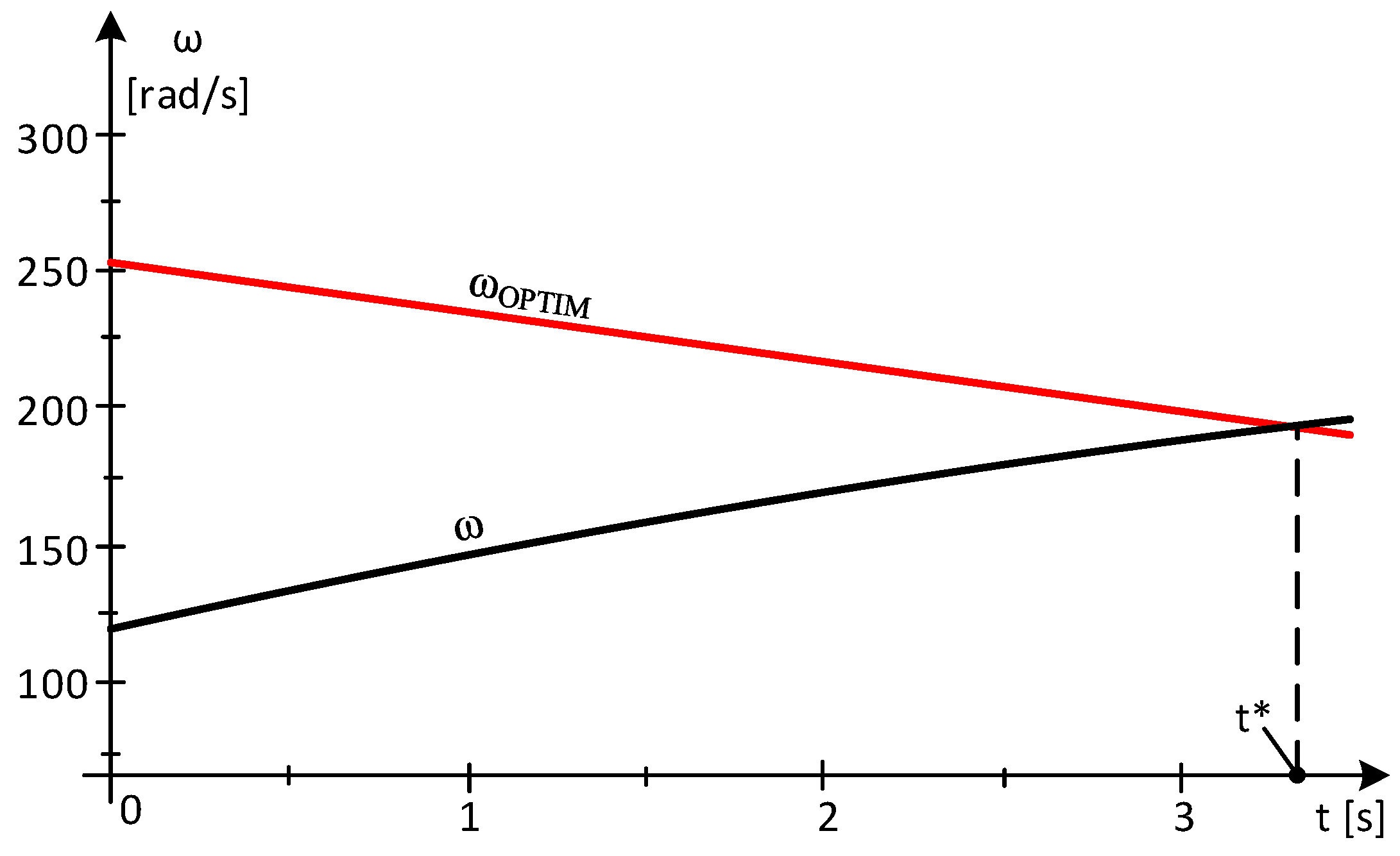
By resolving it, the outcome is the temporal fluctuation of the mechanical angular speed, ω. At time t*, as illustrated in Figure 2, ω—the MAS is measured to have a value of:
ω(3.3) = 197.6 [rad/s]
which is close to the optimal MAS:
ωOPTIM(v) = 24.046·(10.47 − 0.732·t) =
24.046·(10.47 − 0.732·3.3) = 197.67 [rad/s]
At time t = 3.3 [s] when the optimal mechanical angular speed, ωOPTIM and real ω are equal, and the system operates in the turbines maximum power point.
At time t*, the wind speed is measured:
v(3.3) = 10.47 + [(8.13 − 10.47)/3.433]·3.3 = 8.2207 [m./s.]
and, from the WT power characteristic, PWT(v, ω) at ω(3.3):
P = 650860 8.2207 ω 1.7488 · 10 2 · e 41.495 8.2207 ω · 8.2207 3 ω = 197.67
results in power developed by the WT of:
PWT(8.2207) = 1.5516·106 [W]

2.2. Maintaining the Wind System in the Turbine Maximum Power Point

The PEG at the shaft of the electric generator is derived from the power equation when the generator is operating at its MPP:
J(dω/dt)·ω = PWT − PEG
The ωOPTIM, during MPP operation, is determined by the wind speed value as:
ωOPTIM(v) = 24.046·v
In order to achieve optimal performance, it is necessary for the current mechanical angular velocity to be equal to the optimal mechanical angular velocity. This can be expressed as ω = ωOPTIM, resulting in the power equation:
J·(dωOPTIM/dt)·ωOPTIM = PWT-MAX − PEG-OPTIM
or:
24.046·J·(dV/dt)·24.046·v = PWT-MAX − PEG-OPTIM
Thus, based on the knowledge of the dependence of the optimal rotational speed towards wind speed, the optimal power of the electric generator is obtained:
PEG-OPTIM = PWT-MAX − 24.0462·J·(dv/dt)·v
At the equivalent moment of inertia of value J = 511.92 [kg·m2], the optimal electromagnetic power is obtained:
PEG-OPTIM = PWT-MAX − 24.0462·511.92·(dv/dt)·v
= 2792.8·v3 − 2.96·105·(dv/dt)·v
At time t*, once the WT has been brought in MPP, the EG is connected to the grid and charges to the power:
P*EG = P*WT –J·(dω-OPTIM/dt)·ωOPTIM = P*WT –2.96·105·(dv/dt)·v
By employing simulation techniques, an examination is conducted within the MPP region to identify the specific instances in time when power gaps emerge.

2.3. Time Intervals When Wind Speed Increases and Power Gaps Occur

The examination of the current wind speed fluctuations, as illustrated in Figure 1, reveals distinct time periods during which the wind speed increases and falls. When operating within the MPP range, the electric generator’s optimal power output, PEG-OPTIM, will experience fluctuations due to wind conditions, potentially resulting in power gaps at certain times.

Case Study 1—The Appearance of Power Gaps

The analysis focuses on the functioning of the system once it has reached the maximum power point of the turbine. It is assumed that at time t*, the WT operates at point B, which represents the maximum power point as depicted in Figure 1 (Table 1).
At t* = 0 the system operates in state B, at the point of the maximum power of the turbine, when the ωOPTIM is equal to the actual angular velocity ω:
ωOPTIM = ω = 24.046·8.13 = 195.49 [rad/s]
With the v* = 8.13 [m/s], the EG load corresponds to the power P*EG:
P*EG (0) = P*WT-MAX = kp·v3 = 2792.8·8.133 = 1.5008·106
Considering the wind speed variation on the B-C interval as linear, it follows:
vB-C(t) = 8.13 + [(9.52 − 8.13)/6.631 − 3.433)]·t
The wind energy that has been harnessed, denoted as Ewind, is determined through the integration of the power generated by the wind turbine:
Ewind = ∫PWT·dt
or:
Ewind/dt = PWT
The B-C interval is divided into four subintervals:
  • Subinterval 1—at a sampling rate of 1s, at t* = 1 s, the wind speed value results in:
v*1 = 8.13 + [(9.52 − 8.13)/6.631 − 3.433)]·1 = 8.5646 [m/s]
The wind speed varies linearly from 8.13 m/s to 8. 5646 m/s:
vB-C-1(t) = 8.13 + (8.5646 − 8.13)·t = 0.4346·t + 8.13
and the ωOPTIM is:
ωOPTIM-1 = ω = 24.046·(0.4346·t + 8.13)
The equations of motion and energy are obtained as:
511.92 · d ω d t · ω = 650860 0.4346 · t + 8.13 / ω 1.7488 · 10 2 e 41.495 0.4346 · t + 8.13 / ω 0.4346 · t + 8.13 3 1.5008 · 10 6 d E d t = 650860 0.4346 · t + 8.13 / ω 1.7488 · 10 2 · e 41.495 0.4346 · t + 8.13 / ω 0.4346 · t + 8.13 3 ω ( 0 ) = 195.49 E ( 0 ) = 0
In a single second, a wind energy of magnitude Ewind(1) = E(1) = 1.6236·106 [J] is obtained. If the system is functioning at its peak power output, the captured wind energy within that time frame is:
E w i n d M A X 1 = 0 1 P W T M A X · d t = 0 1 2792.8 · 0.4346 · t + 8.13 3 · d t = 1.6254 · 10 6   [ J ]
In the same time interval, the debited electricity is:
E e l e c t r i c a l 1 = 0 1 P E G · d t = 1.5008 · 10 6   [ J ]
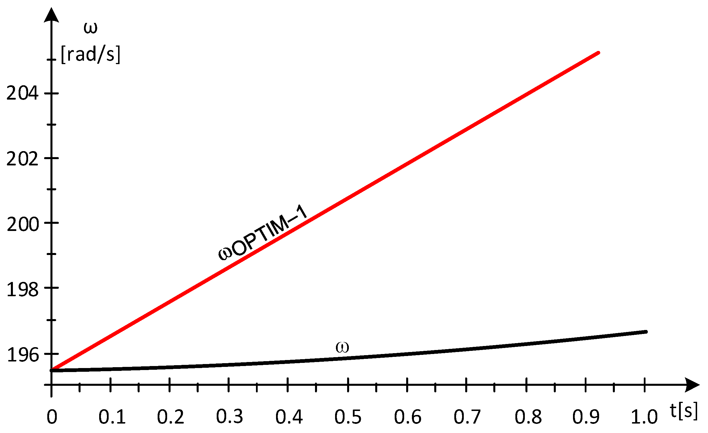
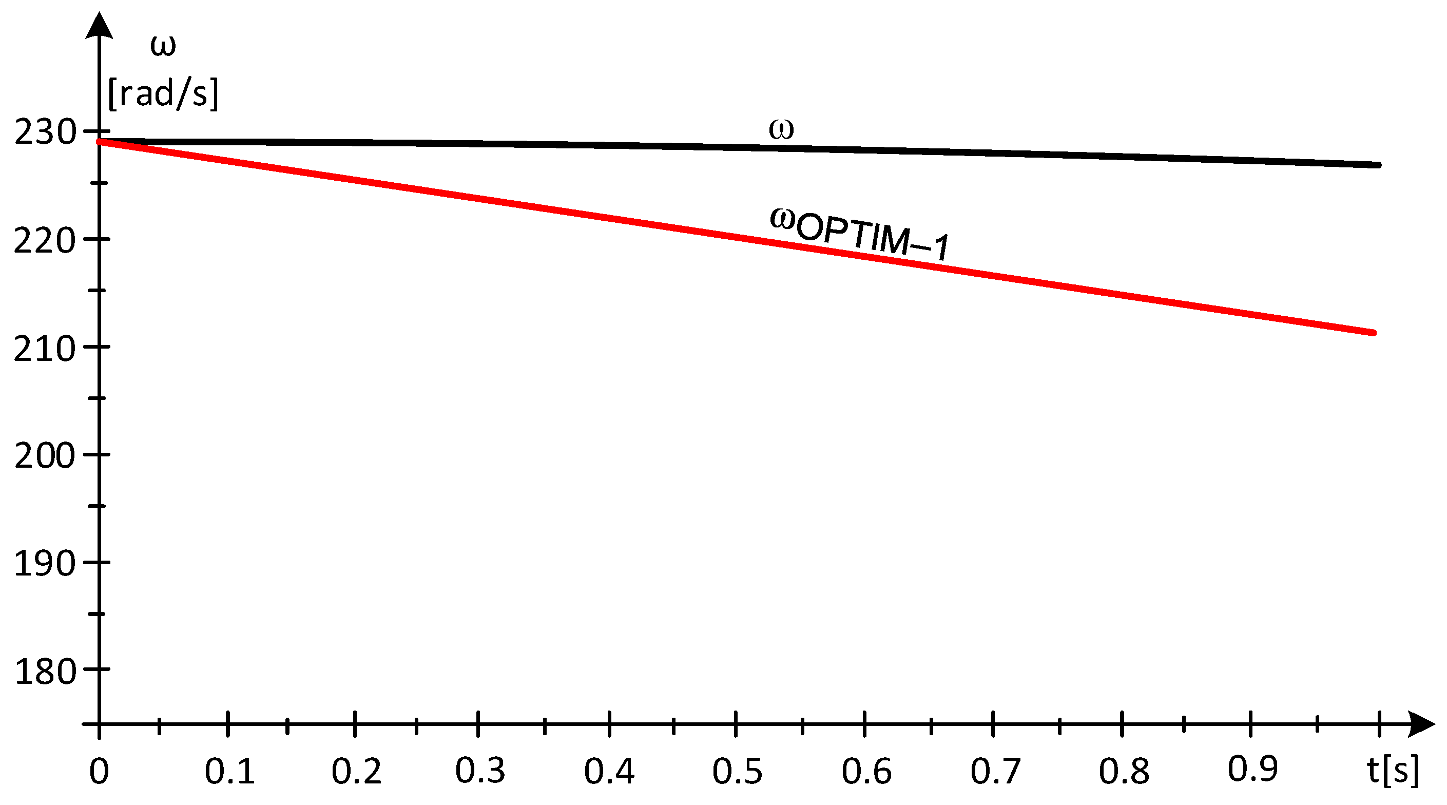
At t* = 1 [s], as shown in Figure 3, the mechanical angular velocity ω has the value ω(1) = 196.71 [rad/s] compared to the optimal mechanical angular speed:
ωOPTIM-1 = ω = 24.046·8.5646 = 205.94 [rad/s]
Since ωOPTIM-1 > ω(1), at t = 1 [s], the maximum power point of the turbine has not been reached. When the value of inertial power is positive, P*INERTIAL > 0:
P*INERTIAL-1 = J·[(ω*OPTIM)2 − (ω*)2]/2Δt
= 511.92·[(205.94)2 − (196.71)2]/2 = 9.5126·105 [W]
on subinterval 2, due to the positive value of the inertial power, the load of the electric generator is decreased to the power level:
P**EG-2 = P*EG − J·[(ω*OPTIM)2 − (ω*)2]/2Δt
= 1.5008·106 − 9.5126·105 = 5.4954·105 [W]
  • Subinterval 2, at t = 2 [s], the value of the wind speed is:
v*2 = 8.13 + [(9.52 − 8.13)/6.631 − 3.433)]·2 = 8.9993 [m/s]
During subinterval 2, the wind speed experiences a linear change from 8. 5646 m/s to 8. 9993 m/s
vB-C-2(t) = 8.5646 + (8.9993 − 8.5646)·t = 0.4347·t + 8.5646
while the optimal mechanical angular speed, ωOPTIM, is:
ωOPTIM-1 = 24.046·(0.4347·t + 8.5646)
In subinterval 2, compared to subinterval 1, the time origin has been shifted by 1 s, and this is repeated thereafter at each analyzed subinterval.
We obtain the equations of motion and energy in the form:
511.92 · d ω d t · ω = 650860 0.4347 · t + 8.5646 / ω 1.7488 · 10 2 e 41.495 0.4347 · t + 8.5646 / ω 0.4347 · t + 8.5646 3 5.4954 · 10 5 d E d t = 650860 0.4346 · t + 8.5646 / ω 1.7488 · 10 2 · e 41.495 0.4346 · t + 8.5646 / ω 0.4346 · t + 8.5646 3 E 0 = 0 ω 0 = 196.71
The wind energy captured in one second is Ewind(1) = E(1) = 1.8883·106 [J]. When operating in MPP, in the same time interval, the captured wind energy is:
E w i n d M A X 1 = 0 1 P W T M A X · d t = 0 1 2792.8 · 0.4346 · t + 8.5646 3 · d t = 1.8927 · 10 6   [ J ]
The produced electricity is:
E e l e c t r i c a l 1 = 0 1 P E G · d t = 5.4954 · 10 5   [ J ]
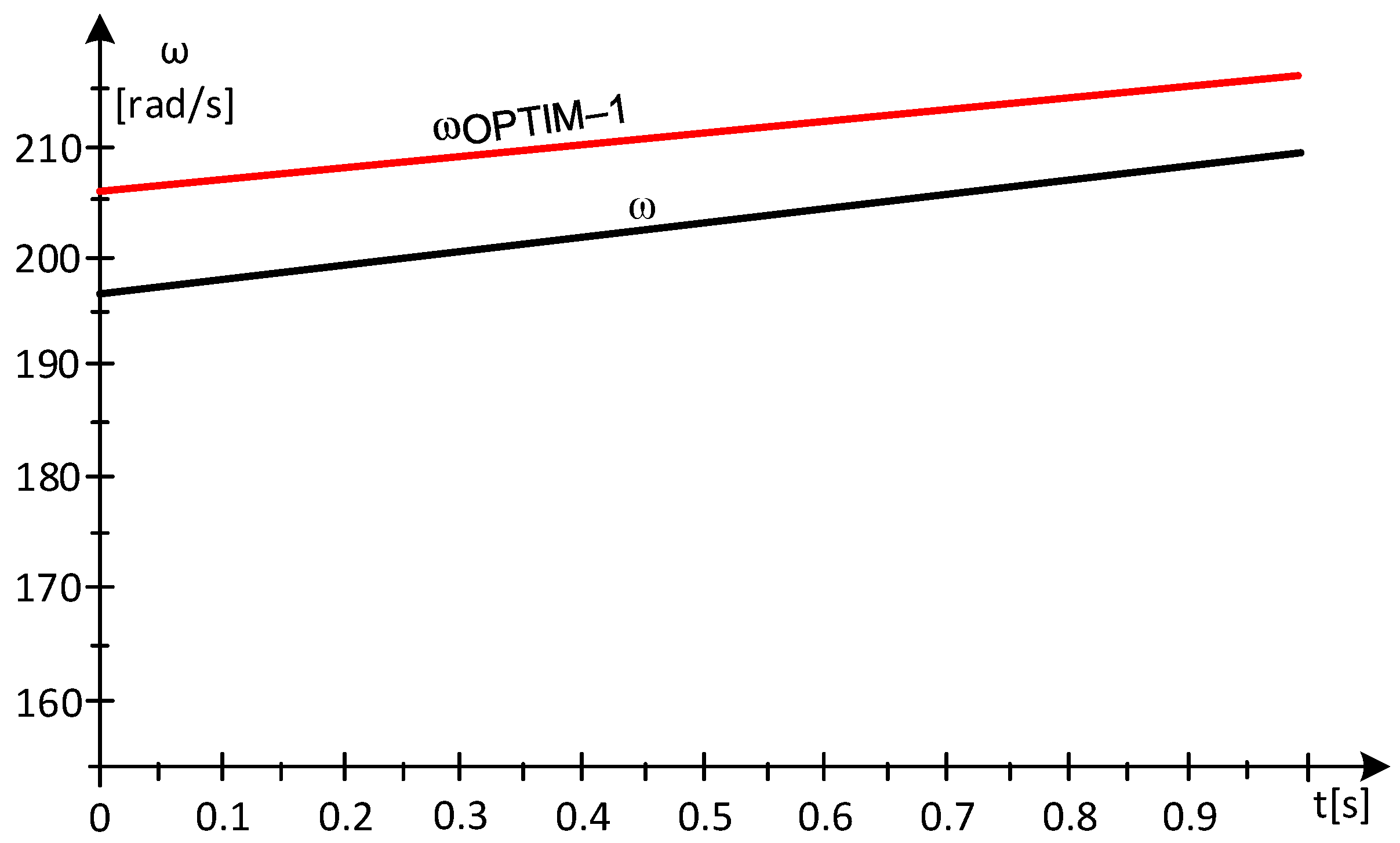
At t = 1 [s], the mechanical angular speed ω has the value ω(1) = 209.58 [rad/s], being lower compared to the optimal mechanical angular speed, as shown in Figure 4.
ωOPTIM-2 = 24.046·8.9993 = 216.4 [rad/s]
Because ωOPTIM-2 ≥ ω(1) at t = 1 [s], the maximum power point of the turbine has not been reached. With the value of inertial power being positive, the EG load should decrease, below subinterval 3, to the value:
P*INERTIAL-3 = J·[(ω*OPTIM)2 − (ω*)2]/2Δt
= 511.92·[(216.4)2 − (209.58)2]/2 = 7.4361·105 [W]
P**EG-3 = P*EG − J·[(ω*OPTIM)2 − (ω*)2]/2Δt
= 5.4954·105 − 7.4361·105 = −1.9407·105 [W] < 0
With the value of the power at EG being negative, it requires its transition into engine mode.
In order for the value of the actual mechanical angular speed to reach, on subinterval 3, the value of the ωOPTIM, it is necessary to switch EG to motor mode. Practically, this is a difficult operating mode, and, for this reason, the generator is disconnected from the network.
  • Subinterval 3, with the power value at the EG being negative on subinterval 3, it discharges. So, P**EG-3 = 0.
At t = 3 [s], the value of the wind speed is:
v*3 = 8.13 + [(9.52 − 8.13)/6.631 − 3.433)]·3 = 9.4339 [m/s]
On subinterval 3, the wind speed has a linear variation from 8.9993 [m/s] to 9.4339 [m/s].
vB-C-3(t) = 8.9993 + (9.4339 − 8.9993)·t = 0.4346·t + 8.9993
and the optimal mechanical angular velocity, ωOPTIM, is:
ωOPTIM-3 = 24.046·(0.4346·t + 8.9993) [rad/s]
So, the system of differential equations governing the motion and energy is obtained in the following form:
511.92 · d ω d t · ω = 650860 0.4346 · t + 8.9993 / ω 1.7488 · 10 2 e 41.495 0.4346 · t + 8.9993 / ω 0.4346 · t + 8.9993 3 d E d t = 650860 0.4346 · t + 8.993 / ω 1.7488 · 10 2 · e 41.495 0.4346 · t + 8.9993 / ω 0.4346 · t + 8.9993 3 E 0 = 0 ω 0 = 209.58
In one second, the captured wind energy is Ewind(1) = E(1) = 2.1869·106 [J].
When operating at the MPP, the captured wind energy, in the same time interval, has the value:
E w i n d M A X 1 = 0 1 P W T M A X · d t = 0 1 2792.8 · 0.4346 · t + 8.9993 3 · d t = 2.1877 · 10 6   [ J ]
The debited electricity is zero E e l e c t r i c a l 1 = 0 [J].
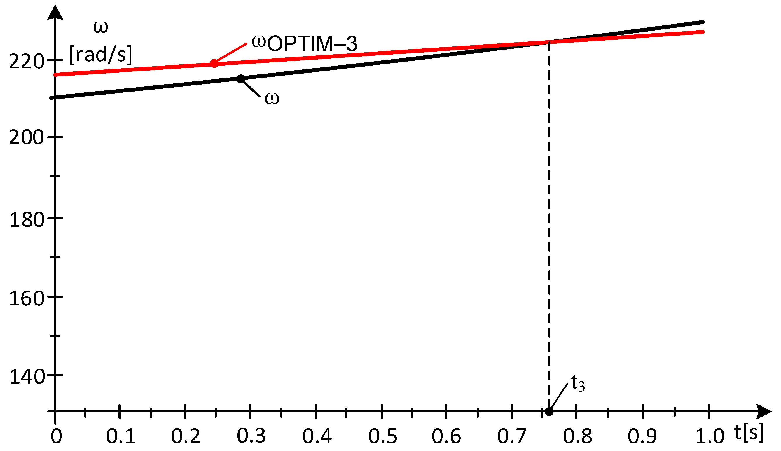
At t* = 1 [s], as shown in Figure 5, the mechanical angular speed ω has the value ω(1) = 229.06 [rad/s] and has exceeded the optimal mechanical angular velocity:
ωOPTIM-3 = 24.046·9.4339 = 226.85 [rad/s]
At the time moment t3, as shown in Figure 5, the ω has reached the optimal value. In this point, the wind turbine operates at the maximum power point at the optimum mechanical angular speed. The value of the captured wind energy is found in the electricity injected into the grid and in the kinetic energy of the rotating masses.
On the three subintervals, the kinetic energies are:
Δ E k i n e t i c 1 = J ω 1 2 ω 0 2 2 = 511.92 196.71 2 195.49 2 2 = 1.2247 · 10 5   [ J ]
Δ E k i n e t i c 2 = J ω 2 2 ω 1 2 2 = 511.92 209.58 2 196.71 2 2 = 1.3384 · 10 6   [ J ]
Δ E k i n e t i c 3 = J ω 3 2 ω 2 2 2 = 511.92 229.06 2 209.58 2 2 = 2.1871 · 10 6   [ J ]
In conclusion, on the three subintervals, the debited energies and powers are (Table 2):
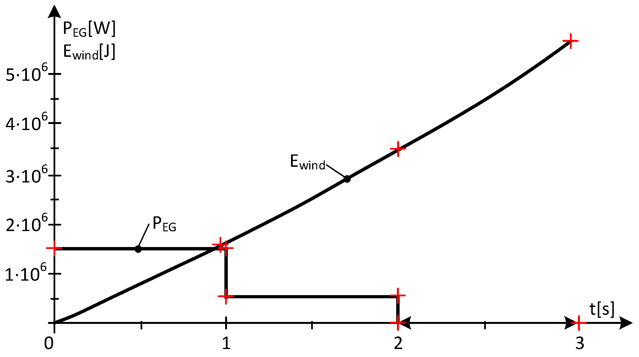
On an interval of 3 s, in which the wind speed increases 8.13 [m/s] < v(t) < 9.4339 [m/s], the energy evolutions are reflected in Figure 6.
Through the energy balance, it can be confirmed that the captured wind energy, Ewind, is found in the injected electricity, Eelectric, and the kinetic energy of the masses in rotational motion, ΔEkinetic.
Energy balance on subinterval 1, Ewind = 1.6236·106 [J] is located in:
Eelectrical + ΔEkinetic = 1.5008·106 + 1.2247·105 = 1.6233·106 [J]
Energy balance on subinterval 2, Ewind = 1.8883·106 [J] is located in:
Eelectrical + ΔEkinetic = 5.4954·105 + 1.3384·106 = 1.8879·106 [J]
Energy balance on subinterval 3, Ewind = 2.1869·106 [J] is located in:
Eelectrical + ΔEkinetic = 0 + 2.1871·106 = 2.1871·106 [J]
The general energy balance on interval 1 → 3 is:
Ewind = 1.6236·106 + 1.8883·106 + 2.1871·106 = 5.6988·106 [J]
is found in the injected electricity, Eelectrical, and the kinetic energy of the masses in rotational motion, ΔEkinetic:
Eelectrical + ΔEkinetic = 1.6233·106 + 1.8879·106 + 2.1871·106 = 5.6983·106 [J]
At t3, maximum wind energy is captured, even if the EG is discharged, (P**EG-3 = 0). The turbine operates at the MPP and at the optimal mechanical angular speed. This energy is not injected into the grid (P**EG-3 is zero) but is found in the kinetic energy of the masses in rotational motion. Apparently, the operation of the turbine is, from an energy point of view, not in the optimal zone. This time moment, presenting a power gap, involves disadvantages for network stability.
Based on the variations of the energy as highlighted in Figure 6, we are able to conclude that:
  • The values of the injected electricity, Electrical, decrease (power at the generator decreases);
  • The differences in the values of the kinetic energies ∆Ekinetic increase and compensate for the decrease in the injected electricity;
In conclusion, during increased wind speed, power gaps can occur if the values of the derivative of the wind speed, dv, and the equivalent moment of inertia, J, exceed certain values.

2.4. Time Intervals in Which the Wind Speed Decreases

Case Study 2—MPP Area at Decreasing Wind Speed

From Figure 7, we select the time interval D-E (Table 3), in which the wind speed decreases.
It is considered that at point D, as shown in Figure 7, the WT operates at the MPP and at the same values of the optimal mechanical angular speeds and real MAS:
ωOPTIM-D = 24.046·9.52 = 228.92 [rad/s]
For the value of the wind speed vD = 9.52 [m/s], the load of the EG is at a PEG-D power of:
PEG-D = P*WT-MAX = kP·v3 = 2792.8·9.523 = 2.4096·106 [W]
On the D-E interval, considering the linear wind speed variation results in:
vD-E(t) = 9.52 + [(7.1245 − 9.52)/43.073-39.858)]·t = 9.52 − 0.73872·t
The D-E interval is divided into three subintervals, similar to the previous case:
  • For subinterval 1, with the sampling being 1s, at t* = 1 [s], the wind speed value results in:
v1* = 9.52 + [(7.1245 − 9.52)/43.073-39.858)]·1 = 8.7813 [m/s]
Wind speed has a linear variation from 9.52 m/s to 8. 7813 m/s:
vD-E-1(t) = 9.52 + (8.7813 − 9.52)·t = 9.52 − 0.7387·t
and the ωOPTIM is:
ωOPTIM-1 = 24.046·(9.52 − 0.7387·t)
In a second, valuable wind energy is captured: Ewind(1) = E(1) = 2.1382·106 [J]
In operation, at the point of maximum power, the wind energy captured over the same time interval has the value Ewind-MAX(1) = 2.1434·106 J, and the electricity flowed has the value Eelectrical(1) = 2.4096·106 J.
At t* = 1 s, as shown in Figure 8, the mechanical angular velocity has the value ω(1) = 226.59 [rad/s] compared to the optimal mechanical angular velocity:
ωOPTIM-1 = 24.046·8.7813 = 211.16 [rad/s]
Since ωOPTIM-1 < ω(1), the value of the inertial power being negative, P*INERTIAL < 0:
P * I N E R T I A L 1 = J ω * O P T I M 2 ω * 2 2 Δ t = 511.92 211.16 2 226.59 2 2 = 1.7289 · 10 6   [ W ]
the load of GE to increase power, on subinterval 2, to:
P * * E G 1 = P * E G J ω * O P T I M 2 ω * 2 2 Δ t = 2.4096 · 10 6 + 1.7289 · 10 6 = 4.1385 · 10 6   [ W ]
  • Subrange 2 to t = 2 [s], the wind speed value is:
v2* = 9.52 + (8.7813 − 9.52)·2 = 8.0436 [m/s]
The wind speed has a linear variation from 8.7813 m/s to 8.0426 m/s:
vD-E-2(t) = 8.7813 + (8.0426 − 8.7813)·t = 8.7813 − 0.7387·t
for which the optimal mechanical angular velocity, ωOPTIM, corresponds to:
ωOPTIM-2 = 24.046·(8.7813 − 0.7387·t)
Proceeding as in the previous case, it follows that in one second, the value of the captured wind energy is Ewind(1) = E(1) = 1.6549·106 [J]. The wind energy captured, in the same time interval, at an operation at the maximum power point is Ewind-MAX(1) = 1.6656·106 J, and the produced electricity has the value Eelectrical(1) = 4.1385·106 J.
At t* = 1 s, the mechanical angular velocity has the value ω(1) = 204.06 [rad/s], compared to the optimal mechanical angular velocity:
ωOPTIM-2 = 24.046·8.0426 = 193.39 [rad/s]
Because ωOPTIM-2 < ω(1), and with the value of the inertial power being negative, P*INERTIAL < 0:
P * I N E R T I A L 2 = J ω * O P T I M 2 ω * 2 2 Δ t = 511.92 193.39 2 204.06 2 2 = 1.0855 · 10 6   [ W ]
increase, on subinterval 3, the load of GE to power:
P * * E G 2 = P * E G J ω * O P T I M 2 ω * 2 2 Δ t = 4.1385 · 10 6 + 1.0855 · 10 6 = 5.224 · 10 6   [ W ]
  • Subinterval 3 to t = 3 [s], the wind speed value is:
v3* = 9.52 + (8.7813 − 9.52)·3 = 7.3039 [m/s]
Wind speed drops from 8.0426 m/s to 7.3039 m/s:
vD-E-3(t) = 8.0426 + (7.3039 − 8.0426)·t = 8.0426 − 0.7387·t
and the optimal mechanical angular velocity, ωOPTIM, is:
ωOPTIM-3 = 24.046·(8.0426 − 0.7387·t)
In one second, the captured wind energy is Ewind(1) = E(1) = 1.2619·106 [J]. The wind energy captured, in the same time interval, at an operation at the maximum power point is Ewind-MAX(1) = 1.2647·106 J, and the produced electricity has the value Eelectrical(1) = 5.224·106 J.
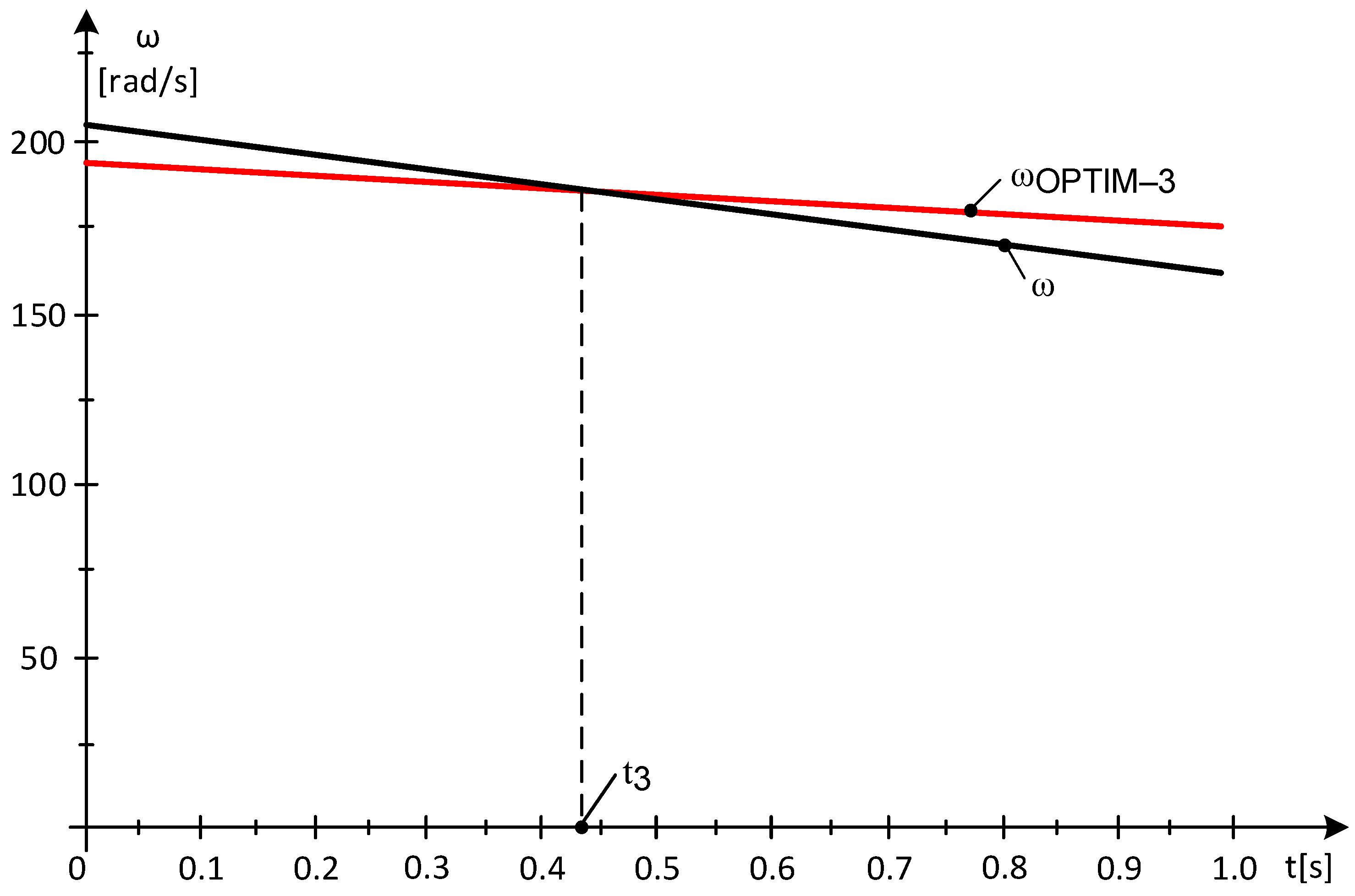
At t* = 1 s, the mechanical angular velocity ω has the value ω(1) = 161.74 [rad/s], compared to the optimal mechanical angular velocity:
ωOPTIM-3 = 24.046·7.3039 = 175.63 [rad/s]
At time t3, as shown in Figure 9, the optimal mechanical angular velocity, ωOPTIM-3, equals the mechanical angular velocity, reaching the maximum power point, and thus the tuning algorithm is validated.
Because ωOPTIM-3 > ω(1), the value of the inertial power is positive, P*INERTIAL > 0:
P * I N E R T I A L 3 = J ω * O P T I M 2 ω * 2 2 Δ t = 511.92 175.63 2 161.74 2 2 = 1.1994 · 10 6   [ W ]
should, over the next sub-time frame, decrease the GE load to:
P * * E G 3 = P * E G J ω * O P T I M 2 ω * 2 2 Δ t = 5.224 · 10 6 1.1994 · 10 6 = 4.026 · 10 6   [ W ]
The value of the captured wind energy is found in the electricity flowed into the system and in the kinetic energy of the rotating masses.
On the three subintervals, the variations of kinetic energies are:
Δ E k i n e t i c 1 = J ω 1 2 ω 0 2 2 = 511.92 226.59 2 228.92 2 2 = 2.7166 · 10 5   [ J ]
Δ E k i n e t i c 2 = J ω 2 2 ω 1 2 2 = 511.92 204.06 2 226.59 2 2 = 2.4835 · 10 6   [ J ]
Δ E k i n e t i c 3 = J ω 3 2 ω 2 2 2 = 511.92 161.74 2 204.06 2 2 = 3.9624 · 10 6   [ J ]
In conclusion, on the three subintervals, the powers and energies are (Table 4):
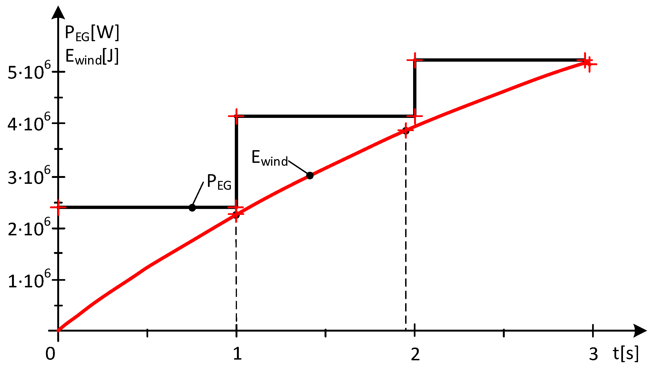
Over an interval of 3 s, during which the wind speed decreases, 7.145 m/s < v(t) < 9.52 m/s, developments in captured wind energy and power output are given in Figure 10.
The energy balance in this case is:
Ewind = Eelectric + ΔEkinetic
and on the three subintervals, this results in:
Ewind-1 = 2.1382·106 ≈ Eelectric + ΔEkinetic = 2.4096·106 − 2.7166·105 = 2.1379·106 [J]
Ewind-2 = 1.6549·106 ≈ Eelectric + ΔEkinetic = 4.1385·106 − 2.4835·106 = 1.655·106 [J]
Ewind-3 = 1.2619·106 ≈ Eelectric + ΔEkinetic = 5.224·106 − 3.9624·106 = 1.2616·106 [J]
In time intervals, when wind speed decreases, no power gaps occur, although mechanical angular velocity tends towards the optimal mechanical angular velocity. The turbine does not operate at the MPP, and yet the power output into the system is greater than the power given by the WT, the difference being from the kinetic energy of the rotating masses. In terms of the stability of the energy system, this is an advantage.
Observations resulting from variations in energy values given in Figure 10:
  • The values of the electrical power flow, PEG, increase, although the wind speed decreases;
  • The differences in the kinetic energy values ΔEkinetic, in absolute value, increase and compensate for the decrease in the values of the captured wind energies;
  • The values of captured wind energies decrease in direct proportion to the decrease in wind speed.
In conclusion, in time intervals, when wind speed decreases, no power gaps occur and, on the contrary, there is an increase in electrical power, whatever the values of the velocity derivative wind, dv/dt, and the equivalent moment of inertia J. This extra electrical power comes, as mentioned, from the kinetic energy of rotating masses. The surplus power must be stored, and only the electricity forecasted in advance given to the national energy system.

3. Results and Discussion

3.1. Fundamental Aspects

With the results obtained, the following relevant aspects can be highlighted:
  • It has been shown that during time intervals when wind speed increases, the power output in the system decreases if the turbine is operating at the point of maximum power;
  • It has been shown that, in the time intervals when the speed decreases, the power debited in the system is higher than the power given by the turbine, which is an advantage for the stability of the energy system;
  • It has been demonstrated that the turbine can operate at its maximum power point at any wind speed value, regardless of restrictions, if a wind energy storage system is available;
  • Bringing the system to the point of maximum turbine power is achieved in the shortest time by decoupling EG from the grid or switching EG to engine mode;
  • By estimating the difference between the optimal mechanical angular velocity and the current mechanical angular velocity, one can prescribe the power value at the generator;
  • The operation of the WT at the MPP is ensured by the correlation of the EG power with the wind speed and its variation;
  • During periods when wind speed increases, power gaps occur (disconnect the generator from the mains) if operation in the energy-optimal area is required;
  • During periods when wind speed decreases, no power gaps occur, although operation in the energy optimal zone is required.

3.2. Discussion

  • The method presented lays the foundation for a control that takes into account wind speed and mechanical angular speed;
  • The system shall be brought to the point of maximum power by calculating the values of the variations in the kinetic energies of the rotating masses, values obtained by measurements;
  • At increasing wind speeds over time, power gaps occur under conditions where operation at the maximum power point is required;
  • At decreasing wind speeds over time, no power gaps occur, although operation is required at the maximum power point and the electrical power debited into the system is greater than the power given by the turbine, the surplus power coming from the various kinetic energies of the rotating masses.

4. Conclusions

In this paper, it was demonstrated that wind energy storage is necessary if the wind turbine is operating at its maximum power point. The power generated by the electric generator comes from the power developed by the wind turbine and from the variation in the kinetic energies of the rotating masses and the energy stored in them during the period of time in which a significant decrease in wind speed occurs (an interesting statement that may seem contradictory). It has been shown that operating in the energy-optimal zone at the peak power point of the turbine requires a system to store captured wind energy. The behavior of the wind turbine at wind speeds variable in time was analyzed, and it was observed that, at significant variations in wind speed, the value prescribed to the generator may be negative, in which case a power gap is created in the national electricity system. The optimal area from an energy point of view was visualized. The simulations presented were based on real variations of wind speed at turbine hub height in the Romanian Black Sea coast area.

Author Contributions

Conceptualization, C.P.C. and G.-O.T.; methodology, C.P.C. and E.S.; software, C.P.C.; validation, C.P.C. and E.S.; formal analysis, E.S.; investigation, C.P.C. and G.-O.T.; resources, C.P.C. and E.S.; data curation, G.-O.T.; writing—original draft preparation, C.P.C.; writing—review and editing, E.S.; visualization, C.P.C. and E.S.; supervision, C.P.C.; project administration, C.P.C. and E.S.; funding acquisition, C.P.C. and E.S. All authors have read and agreed to the published version of the manuscript.

Funding

The publication of this article was supported by the 2024 Development Fund of the UBB.

Data Availability Statement

The data presented in this study are available on request from the first author.

Conflicts of Interest

The authors declare no conflict of interest. The funders had no role in the design of the study; in the collection, analyses, or interpretation of data; in the writing of the manuscript, or in the decision to publish the results.

Abbreviations

Symbol/AbbreviationMeaning
WTwind turbine
MPPmaximum power point
MASmechanical angular speed
EGelectric generator
PEGpower at the electric generator
PWTpower of wind turbine
vwind speed
Jinertia moment
nrotational speed
ωmechanical angular speed
ωOPTIMoptimum mechanical angular speed
nOPTIMoptimum rotational speed
kvproportionality factor
PINERTIALinertial power
ρair density in the wind turbine
Rprotor blade radius
Cp(λ)power conversion coefficient
MWTmoment related to the shaft of the electric generator
MEGelectromagnetic torque at the electric generator
kpthe proportionality factor for power
Ewindwind energy
Eelectricalelectrical energy
ΔEkinetickinetic energy of the masses in rotational motion
NPSNational Power System

References

  1. Adebiyi, A.A.; Moloi, K. Renewable Energy Source Utilization Progress in South Africa: A Review. Energies 2024, 17, 3487. [Google Scholar] [CrossRef]
  2. Kaczmarczyk, B.; Lis, K.; Bogucka, A. Renewable Energy Management in European Union Member States. Energies 2023, 16, 5863. [Google Scholar] [CrossRef]
  3. Früh, W.G. Assessing the Performance of Small Wind Energy Systems Using Regional Weather Data. Energies 2023, 16, 3500. [Google Scholar] [CrossRef]
  4. Guo, D.; Piao, Z.L.; Wang, L.D.; Wang, J.; Lv, Q.Q.; Cao, D.X. The research on the integration of energy storage and generating wind turbine system model. In Proceedings of the China International Conference on Electricity Distribution (CICED), Xi’an, China, 10–13 August 2016. [Google Scholar]
  5. Thapa, S.; Karki, R. Reliability benefit of energy storage in wind integrated power system operation. IET Gener. Transm. Distrib. 2016, 10, 807–814. [Google Scholar] [CrossRef]
  6. Roche, N.; Courtney, J. Optimal Sizing of Energy Storage with Embedded Wind Power Generation. In Proceedings of the 55th International Universities Power Engineering Conference (UPEC), Turin, Italy, 1–4 September 2020. [Google Scholar]
  7. Zhang, H.L.; Liu, J.; Li, W. Optimized Design of Energy-Storage Capacity for Wind Power Generating. In Proceedings of the Asia-Pacific Power and Energy Engineering Conference (APPEEC), Shanghai, China, 27–29 March 2012. [Google Scholar]
  8. Jamii, J.; Mimouni, F. Model of wind turbine-pumped storage hydro plant. In Proceedings of the 9th International Renewable Energy Congress (IREC), Hammamet, Tunisia, 20–22 March 2018. [Google Scholar]
  9. MONSSON. Available online: https://www.monsson.eu/ (accessed on 3 October 2022).
  10. Edrah, M.; Zhao, X.; Hung, W.; Qi, P.; Marshall, B.; Karcanias, A.; Baloch, S. Effects of POD Control on a DFIG Wind Turbine Structural System. IEEE Trans. Energy Convers. 2020, 35, 765–774. [Google Scholar] [CrossRef]
  11. Hussain, J.; Mishra, M.K. An Efficient Wind Speed Computation Method Using Sliding Mode Observers in Wind Energy Conversion System Control Application. IEEE Trans. Ind. Appl. 2020, 56, 730–739. [Google Scholar] [CrossRef]
  12. Sorandaru, V.; Musuroi, S.; Frigura-Iliasa, F.M.; Vatau, D.; Dordescu, M. Analysis of the Wind System Operation in the Optimal Energetic Area at Variable Wind Speed over Time. Sustainability 2019, 11, 1249. [Google Scholar] [CrossRef]
  13. Babescu, M. Sisteme automate de reglare. In Maşina Sincronă: Modelare-Identificare-Simulare; Editura Politehnica: Timisoara, Romania, 2003; pp. 154–196. [Google Scholar]
  14. Papakonstantinou, A.G.; Konstanteas, A.I.; Papathanassiou, S.A. Solutions to Enhance Frequency Regulation in an Island System with Pumped-Hydro Storage Under 100% Renewable Energy Penetration. IEEE Access 2023, 11, 76675–76690. [Google Scholar] [CrossRef]
  15. Sorandaru, C.; Ancuti, M.-C.; Musuroi, S.; Svoboda, M.; Muller, V.; Erdodi, M.G.; Edu, E.R. Fundamental Issue for Wind Power Systems Operating at Variable Wind Speeds: The Dependence of the Optimal Angular Speed on the Wind Speed. In Proceedings of the 2022 International Conference and Exposition on Electrical and Power Engineering (EPE), Iasi, Romania, 20–22 October 2022. [Google Scholar]
  16. Rebello, E.; Watson, D.; Rodgers, M. Performance Analysis of a 10 MW Wind Farm in Providing Secondary Frequency Regulation: Experimental Aspects. IEEE Trans. Power Syst. 2019, 34, 3090–3097. [Google Scholar] [CrossRef]
  17. Dobrin, E.; Ancuti, M.-C.; Musuroi, S.; Sorandaru, C.; Ancuti, R.; Lazar, M.A. Dynamics of the Wind Power Plants at Small Wind Speeds. In Proceedings of the IEEE 14th International Symposium on Applied Computational Intelligence and Informatics (SACI), Timisoara, Romania, 21–23 May 2020. [Google Scholar]
  18. Najih, Y.; Adar, M.; Aboulouard, A.; Khaouch, Z.; Bengourram, M.; Zekraoui, M.; Mabrouki, M. Mechatronic Control Model of a Novel Variable Speed Wind Turbine Concept with Power Splitting Drive Train: A Bond Graph Approach. In Proceedings of the 2020 IEEE 6th International Conference on Optimization and Applications (ICOA), Beni Mellal, Morocco, 20–21 April 2020. [Google Scholar]
  19. Vadi, S.; Gürbüz, F.B.; Bayindir, R.; Hossain, E. Design and Simulation of a Grid Connected Wind Turbine with Permanent Magnet Synchronous Generator. In Proceedings of the 8th International Conference on Smart Grid (icSmartGrid), Paris, France, 17–19 June 2020. [Google Scholar]
  20. Yingyu, A.; Li, Y.; Zhang, J.; Wang, T.; Liu, C. Enhanced Frequency Regulation Strategy for Wind Turbines Based on Over-speed De-loading Control. In Proceedings of the 5th Asia Conference on Power and Electrical Engineering (ACPEE), Chengdu, China, 4–7 June 2020. [Google Scholar]
  21. Chioncel, C.P.; Erdodi, G.M.; Petrescu, D.I.; Elisabeta, S.; Gillich, N. Control of Wind Power Systems Imposing the Current in the Intermediate Circuit of the Converter at Variable Wind Speed. In Proceedings of the 9th International Symposium on Advanced Topics in Electrical Engineering (ATEE), Bucharest, Romania, 7–9 May 2015. [Google Scholar]
  22. Sorandaru, C.; Musuroi, S.; Ancuti, M.C.; Erdodi, G.M.; Petrescu, D.I. The Control of the Wind Power Systems by Imposing the DC Current. In Proceedings of the 10th Jubilee IEEE International Symposium on Applied Computational Intelligence and Informatics, Timisoara, Romania, 21–23 May 2015. [Google Scholar]
  23. Ye, H.; Ding, Y.; Xiao, L.; Li, Q.; Zheng, C.; Wang, Y. Hydro-Tower Pumped Storage-based Wind Power Generator: Short-term Dynamics and Controls. In Proceedings of the 2nd Asian Conference on Frontiers of Power and Energy (ACFPE), Chengdu, China, 20–22 October 2023. [Google Scholar]
  24. Huynh, P.; Tungare, S.; Banerjee, A. Maximum Power Point Tracking for Wind Turbine Using Integrated Generator–Rectifier Systems. IEEE Trans. Power Electron. 2020, 36, 504–512. [Google Scholar] [CrossRef]
  25. Carstea, C.; Butaru, F.; Ancuti, M.-C.; Musuroi, S.; Deacu, A.; Babaita, M.; Stanciu, A.M. Wind Power Plants Operation at Variable Wind Speeds. In Proceedings of the 14th International Symposium on Applied Computational Intelligence and Informatics (SACI), Timisoara, Romania, 21–23 May 2020. [Google Scholar]
  26. Deng, X.; Yang, J.; Sun, Y.; Dongran, S.; Yang, Y.; Joo, Y.H. An Effective Wind Speed Estimation Based Extended Optimal Torque Control for Maximum Wind Energy Capture. IEEE Access 2020, 8, 65959–65969. [Google Scholar] [CrossRef]
  27. Karthik, R.; Sri Hari, A.; Pavan Kumar, Y.V.; John Pradeep, D. Modelling and Control Design for Variable Speed Wind Turbine Energy System. In Proceedings of the 2020 International Conference on Artificial Intelligence and Signal Processing (AISP), Amaravati, India, 10–12 January 2020. [Google Scholar]
  28. Fan, X.; Crisostomi, E.; Zhang, B.; Thomopulos, D. Rotor Speed Fluctuation Analysis for Rapid De-Loading of Variable Speed Wind Turbines. In Proceedings of the 2020 IEEE 20th Mediterranean Electrotechnical Conference (MELECON), Palermo, Italy, 16–18 June 2020. [Google Scholar]
  29. Ma, Y.; Zhang, L.; Yan, J.D.; Guo, Z.; Li, Q.; Fang, Z.; Siew, W.H. Inception mechanism of lightning upward leader from the wind turbine blade and a proposed critical length criterion. Proc. Chin. Soc. Electr. Eng. 2016, 36, 5975–5982. [Google Scholar]
  30. Yokoyama, S.; Yasuda, Y.; Masayuki, M.; Sekioka, S.; Yamamoto Member, K.; Honjo, N.; Sato, T. Clarification of the mechanism of wind turbine blade damage taking lightning characteristics into consideration and relevant research project. In Proceedings of the 2012 International Conference on Lightning Protection (ICLP), Vienna, Austria, 2–7 September 2012. [Google Scholar]
  31. Xingjia, Y.; Yingming, L.; Jieqiu, B.; Zuoxia, X. Research and simulation of direct drive wind turbine VSCF characteristic. In Proceedings of the 2008 IEEE International Conference on Automation and Logistics, Qingdao, China, 1–3 September 2008. [Google Scholar]
  32. Srinivasa Sudharsan, G.; Vishnupriyan, J.; Vijay Anand, K. Active flow control in Horizontal Axis Wind Turbine using PI-R controllers. In Proceedings of the 6th International Conference on Advanced Computing and Communication Systems (ICACCS), Coimbatore, India, 6–7 March 2020. [Google Scholar]
  33. Chioncel, C.P.; Spunei, E.; Tirian, G.O. Visualizing the Maximum Energy Zone of Wind Turbines Operating at Time-Varying Wind Speeds. Sustainability 2024, 16, 2659. [Google Scholar] [CrossRef]
  34. Chioncel, C.P.; Dordescu, M.; Lazar, M.A.; Tirian, O.G. Wind turbine power and optimum energy, at variable wind speeds. In Proceedings of the 24th IEEE International Conference on Intelligent Engineering Systems (INES), Reykjavík, Iceland, 8–10 July 2020; pp. 197–202. [Google Scholar]
  35. Ragheb, M.; Ragheb, A.M. Wind Turbines Theory—The Betz Equation and Optimal Rotor Tip Speed Ratio. In Fundamental and Advanced Topics in Wind Power; Carriveau, R., Ed.; IntechOpen: London, UK; University of Windsor: Windsor, ON, Canada, 2011. [Google Scholar]
  36. Singh, M.; Santoso, S. Dynamic Models for Wind Turbines and Wind Power Plants; University of Texas at Austin: Austin, TX, USA, 2021. [Google Scholar]
  37. Vestas. Available online: https://www.vestas.com (accessed on 1 September 2024).
  38. Wei, D.X.; Wang, J.Z.; Li, Z.W.; Wang, R. Wind Power Curve Modeling with Hybrid Copula and Grey Wolf Optimization. IEEE Trans. Sustain. Energy 2022, 13, 265–276. [Google Scholar] [CrossRef]
  39. Goyal, S.; Maurya, S.K.; Kumar, S.; Agarwal, D. A Consolidation Review of Major Wind Turbine Models in Global Market. In Proceedings of the 2020 International Conference on Power Electronics & IoT Applications in Renewable Energy and Its Control (PARC), Mathura, India, 28–29 February 2020. [Google Scholar]
  40. Baala, Y.; Bri, S. DFIG-Based Wind Turbine Control Using High-Gain Observer. In Proceedings of the 1st International Conference on Innovative Research in Applied Science, Engineering and Technology (IRASET), Meknes, Morocco, 16–19 April 2020. [Google Scholar]
Figure 1. Real variation of wind speed.
Energies 17 05079 g001
Figure 2. Variations of optimal and actual mechanical angular speeds.
Energies 17 05079 g002
Figure 3. Optimal and real MAS variations on subinterval 1.
Energies 17 05079 g003
Figure 4. MAS optimal and real variations on subinterval 2.
Energies 17 05079 g004
Figure 5. Optimal and real MAS variations on subinterval 3.
Energies 17 05079 g005
Figure 6. The variations of captured wind energy and electric power.
Energies 17 05079 g006
Figure 7. D-E time interval with decreasing wind speed.
Energies 17 05079 g007
Figure 8. Optimal and actual VUM variations on subinterval 1.
Energies 17 05079 g008
Figure 9. Optimal and actual MAS variations on subinterval 3.
Energies 17 05079 g009
Figure 10. Variations in captured wind energy and electrical power.
Energies 17 05079 g010
Table 1. Wind speed at operating points.
Time t [s]Speed v [m/s]Point
010.47A
3.4338.13B
6.6319.52C
Table 2. Energies and powers on the three subintervals.
SubintervalEwind [J]Ewind-MAX [J]PEG [W]ΔEkinetic [J]
11.6236·1061.6254·1061.5008·1061.2247·105
21.8883·1061.8927·1065.4954·1061.3384·106
31.1869·1061.1877·10602.1871·106
Table 3. Speed at operating points.
Time t [s]Speed v [m/s]Point
1.19810.47A
39.8589.52D
43.0737.145E
Table 4. Power and energy values on the three subintervals.
SubintervalEwind [J]Ewind-MAX [J]PEG [W]ΔEkinetic [J]
12.1382·1062.1434·1062.4096·106−2.7166·105
21.6549·1061.6656·1064.1385·106−2.4835·106
31.2619·1061.2647·1065.224·106−3.9624·106
Disclaimer/Publisher’s Note: The statements, opinions and data contained in all publications are solely those of the individual author(s) and contributor(s) and not of MDPI and/or the editor(s). MDPI and/or the editor(s) disclaim responsibility for any injury to people or property resulting from any ideas, methods, instructions or products referred to in the content.