Review

Review of AEM Electrolysis Research from the Perspective of Developing a Reliable Model

Faculty of Power and Aeronautical Engineering, Institute of Heat Engineering, Warsaw University of Technology, 21/25 Nowowiejska Street, 00-665 Warsaw, Poland
*
Author to whom correspondence should be addressed.
Energies 2024, 17(20), 5030; https://doi.org/10.3390/en17205030
Submission received: 31 August 2024 / Revised: 19 September 2024 / Accepted: 27 September 2024 / Published: 10 October 2024

Abstract

:
This review thoroughly examines recent progress, challenges, and future prospects in the field of alkaline exchange membrane (AEM) electrolysis. This emerging technology holds promise for eco-friendly hydrogen production. It blends the benefits of traditional alkaline and proton-exchange membrane technologies, enhancing affordability and operational efficiencies by utilizing non-precious metal catalysts and operating at reduced temperatures. This study discusses key developments in materials, electrode design, and performance enhancement techniques. It also highlights the strategic role of AEM electrolysis in meeting global energy transition targets, like achieving Net Zero Emissions by 2050. An in-depth exploration of the operational fundamentals of AEM water electrolysis is provided, noting the technology’s early stage development and the ongoing need for research in membrane-electrode assembly assessment, catalyst efficiency, and electrochemical ammonia production. Moreover, this review compiles results on different cell components, electrolyte types, and experimental approaches, providing insights into operational parameters critical to optimizing AEM performance. The conclusion emphasizes the necessity for continuous research and commercialization efforts to exploit AEM electrolysis’s full potential across diverse industries.

1. Introduction

Hydrogen is increasingly central to the shift toward a sustainable energy framework, acting as a dynamic energy medium with varied applications in transportation, industrial processes, and energy storage. Alkaline exchange membrane (AEM) electrolysis is capturing interest as a favorable option compared to conventional proton-exchange membrane (PEM) and alkaline electrolysis systems, noted for its cost-effectiveness, operational efficiency, and reduced environmental footprint. Its distinction lies in employing non-precious metal catalysts and the capability to operate at lower temperatures. This review explores the latest developments in AEM electrolysis research, including innovations in material science, new electrode designs, and enhanced performance strategies.

1.1. Electrolyzer Market

Electrolyzers represent a rapidly evolving sector within the energy market. They play a pivotal role in generating low-emission hydrogen from renewable or nuclear sources. While the growth of electrolysis capacity for hydrogen production has been on the rise in recent years, there was a noticeable slowdown in 2022, with around 130 MW of new capacity being added—45% less than the previous year. Despite this, the production capacity of electrolyzers has seen an increase of over 25% from the previous year, achieving close to 11 GW annually in 2022. The completion of ongoing projects could potentially elevate the installed capacity of electrolyzers to between 170 and 365 GW by 2030.
The growth of electrolysis capacity, starting from a modest base, necessitates considerable acceleration to align with the Net Zero Emissions by 2050 (NZE) Scenario, as technology readiness level of various electrolyzers in not very high yet, as presented in Figure 1. This ambitious target demands that the installed capacity of electrolysis exceed 550 GW by the year 2030 [1].
The market features four primary electrolyzer technologies: PEM, ALK, SOEC, and AEM, each at varying stages of technological development. Electrolyzers stand out among competing technologies primarily for their versatile applications. A comparative analysis of AEM electrolysis with other water electrolysis technologies like proton-exchange membrane (PEM) and Solid Oxide Electrolyzer Cells (SOEC) highlights their respective benefits and constraints. AEM electrolysis typically functions within a voltage range of 1.8–2.2 V and achieves current densities of 0.5–3.0 A/cm2 at temperatures between 40 and 90 °C. This technology reduces capital costs through the utilization of non-precious metal catalysts. In contrast, PEM electrolyzers, though operating at similar voltages and achieving moderate current densities (up to 2 A/cm2), necessitate the use of costly platinum-group metals. SOECs, capable of higher efficiencies with electrical-to-hydrogen conversion rates exceeding 80% at temperatures above 700 °C, encounter challenges related to material degradation due to high operational temperatures. While PEM electrolysis achieves higher current densities, AEM electrolysis presents a cost-effective alternative by providing comparable efficiencies at reduced costs, positioning it as a viable choice for extensive hydrogen production once issues of durability and long-term stability are addressed.

1.2. Hydrogen Production

Electrolyzers play an essential role in hydrogen production, which is emerging as a clean and adaptable energy carrier, offering a sustainable alternative to hydrogen derived from fossil fuels such as natural gas. This shift can significantly lessen reliance on fossil resources and reduce the environmental harms associated with the extraction and combustion of fossil fuels. When produced from renewable energy sources, hydrogen serves various roles: it can power vehicles, supply raw materials for industrial processes, and act as a storage medium for energy. Thus, hydrogen is increasingly recognized as a crucial element in the shift toward a low-carbon economy.

1.3. Chemical and Industrial Processes

Hydrogen generated through electrolysis has broad applications across different industries, notably in the production of ammonia, methanol, and various other chemicals. Additionally, it functions as a reducing agent in metallurgical operations, contributing to the reduction in the carbon footprint associated with these industries.

1.4. Energy Storage

Electrolyzers are crucial in energy storage systems, particularly in integrating renewable energy sources. Surplus electricity generated from wind and solar can be harnessed to produce hydrogen via electrolysis. This hydrogen can then be stored and subsequently converted back into electricity using fuel cells or similar technologies during peak energy demands or when renewable sources are inactive.

1.5. Grid Balancing

Electrolyzers can enhance grid stability by offering services like frequency regulation and peak shaving. They can be dynamically managed to either absorb surplus electricity or generate additional power as required, aiding in grid balancing and boosting its overall reliability.

1.6. Global Energy Transition

Within the broader framework of combating climate change and transitioning to sustainable energy systems, electrolyzers are viewed as a crucial technology for leveraging renewable energy sources and cutting carbon emissions. They facilitate the decarbonization of multiple sectors, including transportation, industry, and heating. Utilizing hydrogen produced from renewable energy in fuel cells or as an industrial feedstock can significantly reduce greenhouse gas emissions and diminish air pollution. Despite facing challenges such as the need for cost reduction and efficiency enhancements, electrolyzers are seen as a pivotal technology for fostering a more sustainable and cleaner energy future. Ongoing research and development are expected to further solidify the role of electrolyzer technology across various economic sectors.

1.7. Technology Description

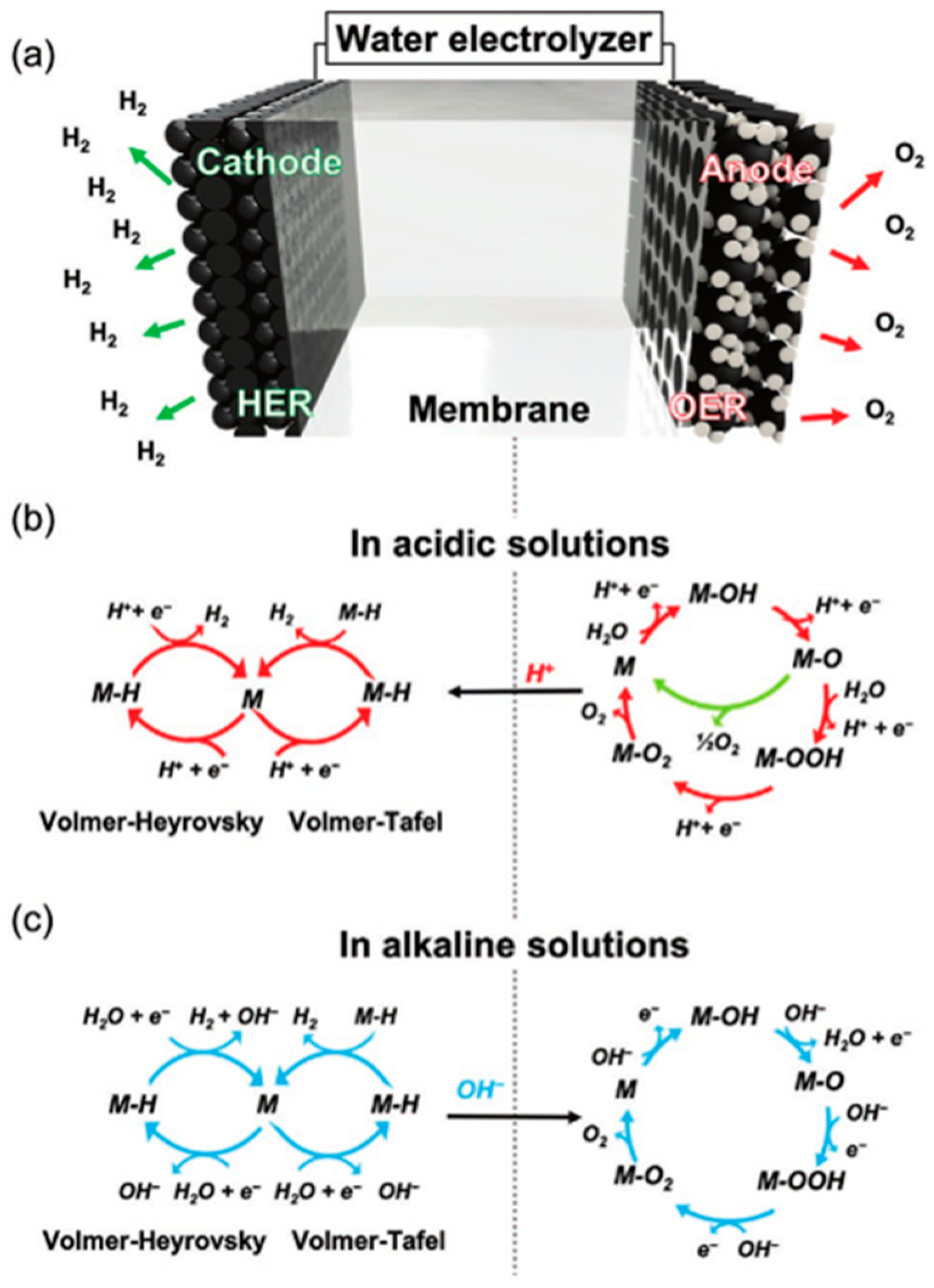
Anion-exchange membrane electrolyzers for water electrolysis (AEM WE) represent a technological fusion of traditional alkaline electrolyzers (ALK) and proton-exchange membrane electrolyzers (PEM). Like ALK electrolyzers, AEM systems do not require noble metals for catalysts but use an alkaline solution to maintain high efficiency, albeit at potentially lower concentrations that reduce operational risks and material corrosion. Similar to PEM electrolyzers, AEM employs a membrane, but this one is exclusively permeable to OH- anions, enhancing its functionality under high-pressure conditions (Figure 2). However, the durability of the membranes used in AEM electrolyzers poses a significant challenge and is a critical obstacle impeding the broader adoption of this technology.
The operational principle of ion-exchange electrolyzers is outlined in Figure 2. In this process, the membranes facilitate the exchange of OH anions, effectively undergoing the reaction OH + OH = H2O + 1/2 O2 + 2e, or H2O22− from the anode to the cathode side (see Equations (1)–(4)). Consequently, hydrogen is produced at the cathode while oxygen emerges at the anode. This document includes citations from the literature that discuss research on AEM electrolyzers, highlighting their function and relevance.
4 O H 3 O H + e + O H *
O H * + 3 O H * + e 2 O H + e + O * + H 2 O
O * + H 2 O + 2 O H + 2 e O H + 3 e + O O H * + H 2 O
O O H * + H 2 O + O H + 3 e 4 e + 2 H 2 O + O 2
The cathode reaction (refer to Equations (5)–(7)) mainly involves the reduction of water molecules to generate hydrogen gas. This reaction typically progresses through the combined mechanisms of the Volmer, Tafel, and Heyrovsky steps. During these steps, water molecules are adsorbed and dissociated to produce hydrogen and hydroxide ions, which together facilitate the overall hydrogen evolution reaction.
2 H 2 O + 2 e 2 H * + 2 O H
2 H * H 2
H 2 O + H * + e H 2 + O H
This technology is continually evolving, with ongoing experiments focused on new materials, particularly in the areas of catalyst and membrane enhancements, as noted in recent studies [3]. While AEM electrolyzers have not been as extensively explored as PEM systems, breakthroughs in recent years have enabled their commercial deployment by companies such as Ionomer and Versogen. Furthermore, AEM electrolyzers are now being tested in pilot-scale demonstrators, marking a significant transition from purely laboratory-based investigations. The primary focus of these studies is on experimental characterization to decipher the fundamental mechanisms at play. However, a definitive model that could serve as a benchmark for comparing a broad range of research findings is still lacking, which is necessary for further advancing the development of this technology.

1.8. Research Overview

As the least developed among contemporary technologies, AEM electrolyzers necessitate extensive scientific research. The aim of this article is to provide a comprehensive overview of the existing research and to outline potential future research avenues. This overview will be systematically structured according to different research areas.

1.9. Electrolyzer Efficiency

When modeling electrochemical devices, it is vital to identify and define the critical constants and variable parameters of the electrolyzer. These parameters can be categorized into three main groups: material parameters, thermal-flow parameters, and parameters gathered through experimental observations, which are crucial for determining constants that cannot be established by other means.
Material parameters are associated with each key component of the intricate electrolyzer cell, specifically the anode, cathode, and electrolyte. Notably, in AEM electrolyzers, the electrolyte includes both the membrane and the solution used—typically KOH—whose concentration and type modify the electrolysis conditions, thereby affecting the overall ionic conductivity of the electrolyte. Moreover, each component is defined by the type of material utilized, which can either facilitate or impede the process. Factors such as electrical conductivity (resistance), which enables electron flow; thickness (which determines the distance electrons or ions travel); porosity (affecting the movement of liquids and gases through the material); and surface finish (which influences interactions with the environment) are all crucial. These material parameters dictate the cell’s behavior under any given conditions and are considered stable over a designated period, barring any degradation processes.
The second category of parameters involves thermal-flow characteristics. These parameters outline the environmental conditions of the electrolyzer cell, which directly impact the rate of internal processes. Temperature is a vital thermodynamic parameter; higher temperatures can accelerate reaction rates, but they also risk hastening the degradation of components like the membrane. Operating pressure and the pressure differential between the anode and cathode are critical in facilitating ion transport across cell compartments, promoting electrochemical reactions. However, markedly higher pressures can increase gas transfer capabilities, enhance crossflow, and potentially elevate the risk of explosive mixtures involving oxygen and hydrogen. Additionally, the volume of gases moving across the anode and cathode surfaces affects the flow rate, influencing whether the flow is laminar or turbulent and the availability of reactants required for the reactions.
To thoroughly understand the electrochemical processes and operational dynamics of AEM electrolyzers, it is crucial to leverage experimental research, especially analyzing the voltage-current curve. This curve is instrumental in validating assumptions within electrochemical and process models. Additionally, electrochemical impedance spectroscopy (EIS) serves as a vital tool for the detailed characterization of individual electrolyzer cells. EIS facilitates the measurement of specific resistances within electrolyzer cell components, aids in establishing equivalent circuits, and enhances the overall capabilities for characterizing distinct cells.
This article details the latest findings on characterizing AEM electrolyzers and the methodologies employed in conducting laboratory-based research on these systems.
The publication by Lim et al. (2019) [4] examines the influence of various parameters, including those pertinent to the manufacturing, assembly, and operational phases of cell production. This study highlights the significant role of operating temperature while providing less clear results regarding the clamping force and torque applied to assembly screws. Similarly, the research conducted [5] explores a range of parameters from manufacturing through to operational practices. The researchers successfully achieved high current densities at comparatively low voltages by optimizing three crucial factors: (1) a revised method for manufacturing the membrane-electrode assembly (MEA), (2) thorough evaluation and selection of optimal MEA parameters and operating conditions, and (3) effective use of a membrane–ionomer combination.
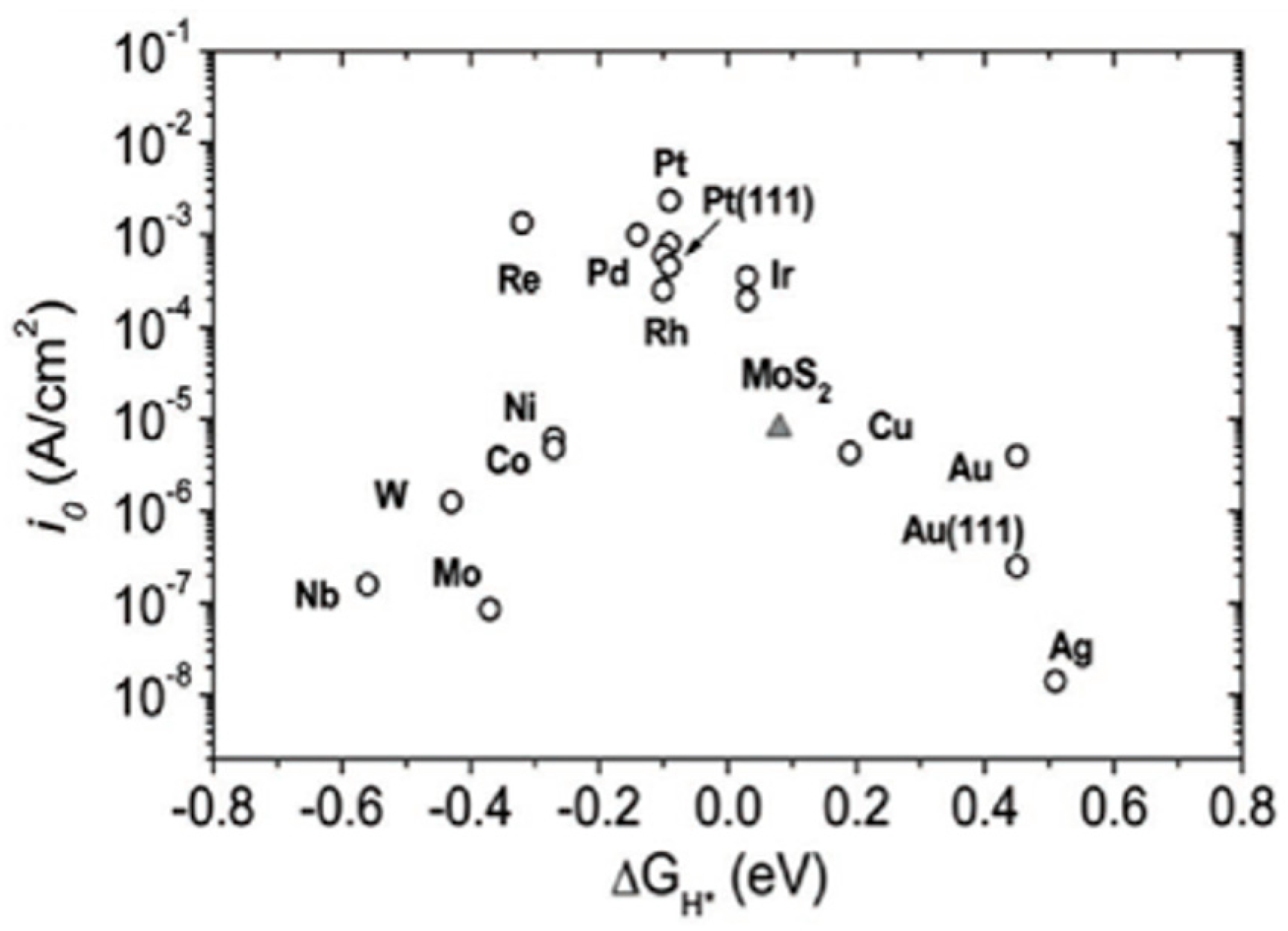
Figure 3 illustrates the effect of chosen catalysts on the performance of anion-exchange electrolyzers, highlighting that the optimal results are obtained when using noble metals.
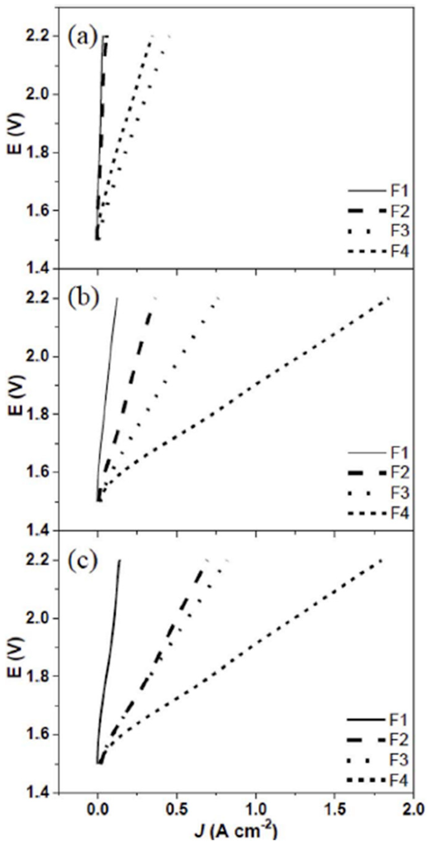
Figure 4 displays the polarization curves from an AEM water electrolyzer operating at 50 °C, utilizing membrane-electrode assemblies (MEAs) that incorporate 20 wt% and 9 wt% PTFE binders in the anode and cathode, respectively, denoted as BC20. The data showcase the electrolyzer’s performance across three distinct operational cycles—the 10th (a), 50th (b), and 100th (c)—under different cathode feed modes, providing critical insights into the electrolyzer’s efficiency and durability over time.

2. An Overview of Laboratory Investigation Techniques for AEM Membrane-Based Electrolysis
While recent improvements in electrocatalyst design are notable, there is room for further enhancement, particularly by developing catalysts that offer improved durability, activity, and selectivity under the demanding alkaline conditions typical in AEM electrolysis. Innovative strategies like doping with transition metals, employing nanostructures, and using hybrid catalysts that merge various materials could enhance both the efficiency and durability of electrocatalysts. Moreover, utilizing in situ characterization methods, such as operando spectroscopy, can provide deeper insights into the dynamic shifts in catalyst structure and composition during electrolysis. This understanding could drive more precise advancements in catalyst design.
Understanding the structure–performance relationship in AEM electrolysis materials is essential for enhancing both efficiency and durability. Nanostructured catalysts, like nickel-based materials doped with cobalt or iron, significantly increase the active surface area, which boosts the kinetics of the hydrogen and oxygen evolution reactions. This enhancement not only multiplies the number of active sites but also improves reactant accessibility, leading to increased current densities and reduced overpotentials.
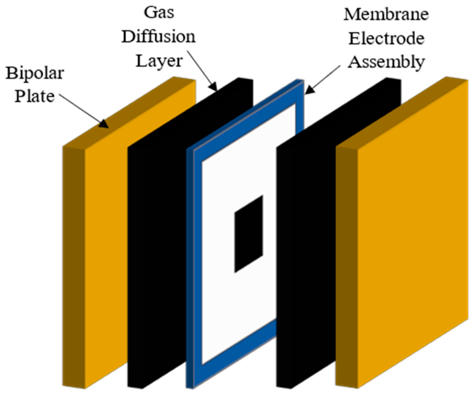
The porosity of the electrode also plays a vital role by facilitating efficient gas diffusion, which is crucial for maintaining optimal reaction conditions. Moreover, the characteristics of the ion-exchange membrane, particularly its ionic conductivity and water management capabilities, directly affect the internal resistance and overall system efficiency. An optimally designed membrane achieves a balance between ion transport and minimal gas crossover, enhancing both performance and stability. Typical construction of an alkaline water electrolyzer is presented in Figure 5.
To advance AEM electrolysis, research should prioritize linking these structural parameters with operational outcomes, such as high current density operation and long-term stability. This approach will guide the development of more efficient and durable systems.
A relevant study, detailed in [6], showcases experimental research on a highly efficient membrane-electrode assembly utilizing platinum group metals for water electrolysis within an anion-exchange membrane. In this study, the anodic catalyst used was Acta 3030 [7], a material comprising CuCo Ox synthesized through the co-deposition of Co (NO3)2-6H2O and CuSO4-5H2O. X-ray diffraction analysis confirmed the material’s crystalline phase with a spinel structure indexed by the Fd3m space group. The specific surface area of the CuCo Ox, as measured by nitrogen physisorption using a Quadrasorb SI device from Quantachrome, was approximately 100 m2/g, with a pore volume of 0.35 cm3/g.
For the cathode side of the hydrogen evolution reaction (HER), the study employed a commercial catalyst, Acta 4030. This catalyst is a nanostructured nickel-based material coated on a CeO2-La2O3/carbon substrate. The preparation of this catalyst involved two main steps: firstly, the deposition of inorganic Ce and La precursors onto the carbon substrate, followed by a calcination process; secondly, the deposition–precipitation of nickel hydroxide onto the CeO2+La2O3/carbon substrate, which was then reduced. The resultant material exhibited high porosity, with a BET surface area of 180 m2/g and a pore volume of 0.59 cm3/g, featuring nickel crystallites averaging 17 nm in size, as indicated by XRD peak width analysis.
The anion-exchange membrane used in all experiments was the A201 membrane from Tokuyama Corporation, Tokyo, Japan. This membrane, in its dry form, measured 28 μm in thickness and was characterized by an ion-exchange capacity of 1.8 mmol/g, a water uptake of 30%, and an ionic conductivity of 12 mS/cm in the HCO3 form. The operating voltage and electric current were meticulously controlled and monitored using an Arbin multichannel testing system (Arbin Instruments, College Station, TX, USA) operated via MITS Pro software.
In the research documented by [8], the application of AEM for electrochemical ammonia synthesis from water and nitrogen under ambient conditions was explored. Platinum electrodes (20% Pt on a carbon surface, 0.5 mg/cm2) were utilized on both sides of the membrane, and ammonia was synthesized by introducing nitrogen into the cathodic side of the electrolyzer. Nitrogen gas (99.999% purity) was continuously bubbled into the cathode chamber at a flow rate of 100 mL/min. The study examined current–voltage characteristics ranging from 1.5 to 2.5 V, with initial current densities spanning from 0.21 mA/cm2 to 7 mA/cm2. A Faraday efficiency of 0.18% in ammonia production was achieved at an operating voltage of 2 V. Additionally, electrochemical impedance spectroscopy (EIS) was conducted to assess the impact of voltage on cell resistance, finding an electrolyte resistance of 0.282 ohms under open-circuit voltage conditions, with a corresponding electrical conductivity of 0.32 mS/cm. The study further identified a critical point at 2 V, beyond which the cell predominantly produced hydrogen rather than ammonia.
The literature contains a diverse array of review articles discussing various facets of anion exchange electrolysis technology. One review, referenced in [9], focuses on the membranes and catalysts utilized in such electrolyzers, while another review [10] delves into the production techniques for anion-conductive membranes. The latter review elaborates on the principles of fuel cells and electrolyzers that employ anion-conductive membranes, detailing the structure of these membranes and the methods used in their preparation. It addresses crucial factors that influence membrane properties, such as swelling ratio, water uptake, membrane water content, water contact angle, hydroxide conductivity, and alkaline stability. It specifically examines imidazole-based materials, including benzimidazolium cations, which enhance stability and efficiency thanks to their large electron-donating functional groups. The review also considers the potential of non-nitrogen AEMs like phosphonate, sulfonic, and metallic cations as alternatives to traditional quaternary ammonium (QA) cations in AEMs. Covering both ambient and elevated temperature operations (up to 200 °C), the review extensively describes the phenomena at the anodes and cathodes, especially those occurring in the OH electrolyte and the effects of various contaminants, although it lacks experimental data such as current-voltage curves.
Further insights are provided in an additional review by Vincent and Bessarabov [11], which outlines hydrogen production methods using AEM technology. This article introduces the fundamental principles and components of such electrolyzers, discusses operational conditions, and touches on modeling phenomena. It also highlights the primary challenges this technology faces and proposes directions for further research, although it remains high-level without delving into detailed specifics.
Similarly, another article by Vincent and Bessarabov [12] offers an overview of hydrogen production methods utilizing AEM technology, reiterating the basic principles, fundamental components, and operational conditions. It too outlines the significant challenges and research directions, maintaining a broad approach without extensive detail. These articles serve as valuable introductions to the topic, setting a groundwork for future in-depth research in the field.
Figure 5. Construction of an alkaline water electrolyzer cell [13].
Energies 17 05030 g005
Below is a structured overview of the current research priorities in anion-conductive polymer technology:
  • Research on Improved Anion-Conductive Polymer Materials (Membranes and Ionomers): This area focuses on developing new materials that enhance the functionality and efficiency of anion-exchange membranes and associated ionomers. The goal is to create polymers that provide better chemical stability and improved ion exchange capacities.
  • Research on Improving Hydroxide Ion Conductivity: This research aims to enhance the ionic conductivity of hydroxide ions within the electrolyte systems, which is crucial for increasing the efficiency of electrochemical reactions in systems like fuel cells and electrolyzers.
  • Research on the Phenomena of Oxygen Evolution Reaction (OER) and Hydrogen Evolution Reaction (HER): Investigating these fundamental electrochemical reactions is essential for optimizing the efficiency of water electrolysis. Understanding the kinetics and mechanisms of OER and HER can lead to significant improvements in energy conversion rates.
  • Physical and Electrochemical Characterization of MEA (Membrane Electrode Assembly): This research involves detailed studies of the MEA’s properties, focusing on aspects such as durability, ion transport, and electrochemical stability. Physical and electrochemical techniques are employed to evaluate how different materials and construction techniques affect the performance of the MEA.
  • Implementation and Scaling up through the Commercialization of this Electrolysis Method: The final step involves taking the research from the lab to the market, which includes scaling up the production processes and implementing the technology in commercial applications. This phase is critical for assessing the viability of the electrolysis methods and ensuring they meet industry standards for commercial use.
Our research is designed to address a current knowledge gap by performing detailed physical and electrochemical characterization of the membrane electrode assembly (MEA). This effort aims to deepen our understanding of the underlying processes occurring within the MEA, which will inform the development of phenomenological models. Through the application of techniques such as voltammetry and electrochemical impedance spectroscopy (EIS), we intend to build models that establish both empirical and theoretical predictive relationships for the operational parameters of the system. This approach will enhance the precision and effectiveness of MEA technologies in practical applications.
The upcoming review article [13] delineates crucial research areas necessary for the widespread commercial implementation of AEM electrolyzers. It highlights the importance of advancing the materials used, particularly focusing on catalysts and membranes. Additionally, the article underscores the need to enhance the capacities of these devices significantly, from 5% to 200%, advocating for operations under higher pressures of up to 70 bar and at elevated temperatures exceeding 80 °C. Operating at these higher temperatures could potentially increase reaction rates, thereby improving the efficiency of electrolysis by up to 75% and reducing the energy costs associated with hydrogen production to 42 kWh/kgH2.
Another review article [14] points to the need for establishing standardized processes for testing and performance evaluation. This article emphasizes the necessity of generating detailed protocols concerning the configuration of test setups, the selection of electrolyzers and their components, and the preparation of electrodes. Additionally, it discusses the need to fine-tune operational variables such as the torque of mounting screws, pressure settings, temperature, electrolyte type, and power modes. These standardizations are vital for ensuring consistent and reliable assessments of electrolyzer performance across the industry.

3. Cell Components

The authors of [15] provide some of the most significant recent contributions to the literature on AEM systems. This review comprehensively lists the most crucial materials, such as catalysts, membranes, and ionomers, alongside key operating conditions, including electrolyte types and temperatures. It also details the optimal voltage and current performances observed in recent studies.

3.1. Electrolyte Handling in Anion-Exchange Membrane Electrolyzers

Anion-exchange membrane electrolyzers can operate using different methods of electrolyte management, primarily utilizing water and/or aqueous KOH solutions. The study documented in [3] evaluates four distinct approaches to handling the electrolyte: continuous water feeding throughout the electrolysis process, introducing water only at the start of operations, continuous feeding of a 0.5 M aqueous KOH solution, and a method where aqueous KOH solution is fed only during the initial phase of operation. These methodologies are analyzed to determine their effectiveness in optimizing the performance of the electrolysis system.
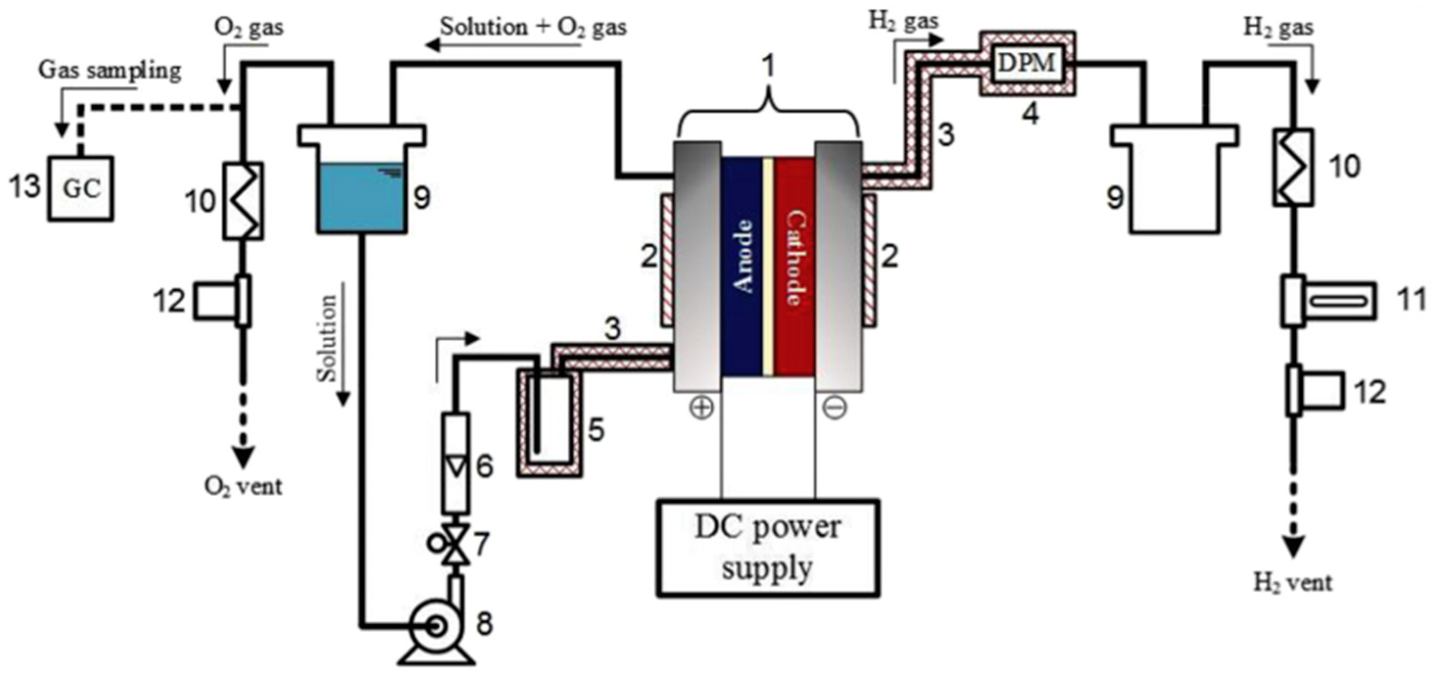
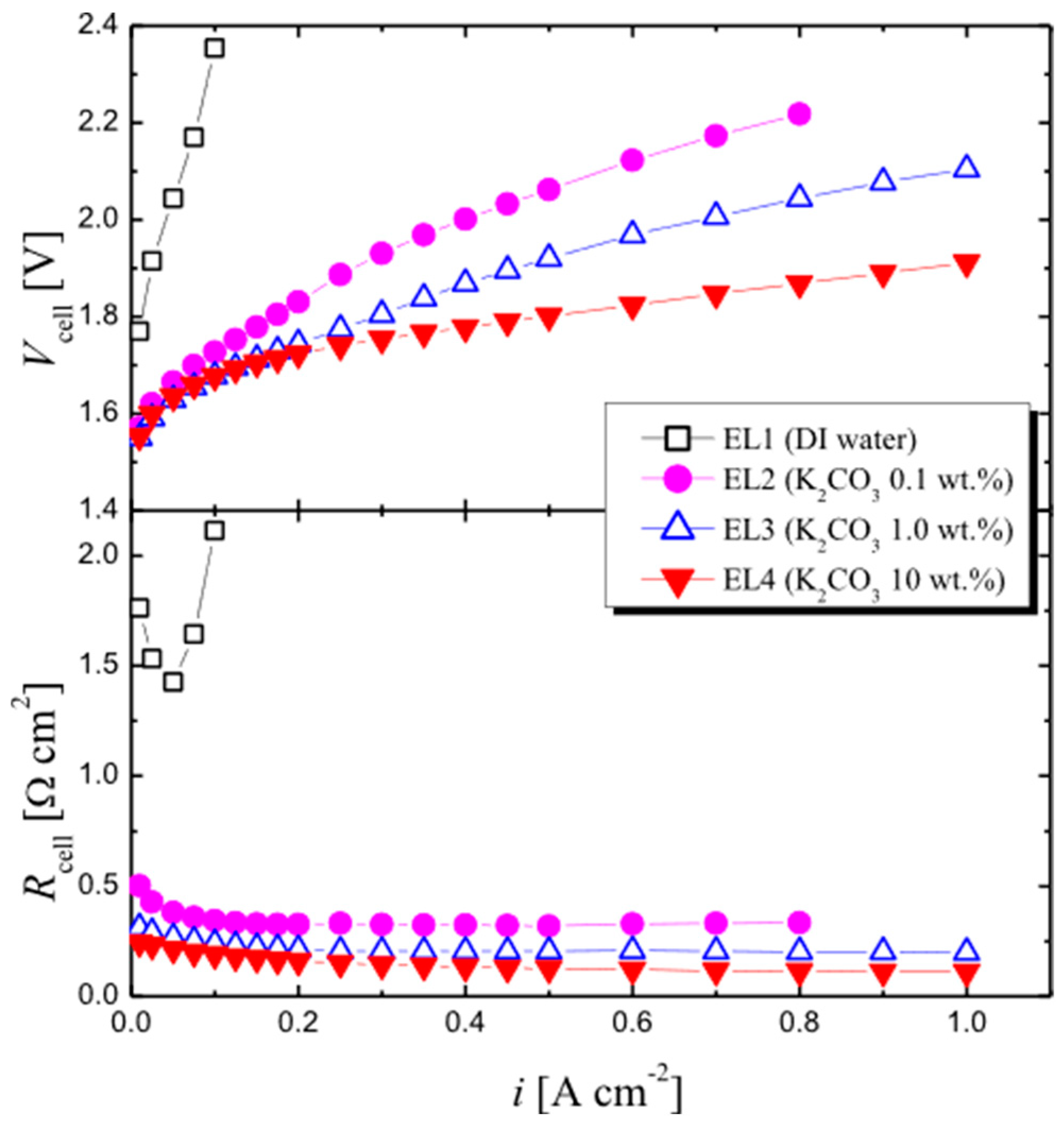
More advanced research findings are presented in [12], where different electrolyte compositions were evaluated, including potassium carbonate solutions (Figure 6). These results were compared with the traditional electrolyte, potassium hydroxide, to assess performance variations (see Table 1). This comparative analysis provides deeper insights into how different electrolyte formulations impact the overall efficiency and effectiveness of anion-exchange membrane electrolyzers (Figure 7).

3.2. Materials

The study detailed in [16] focuses specifically on the material-related aspects of AEM-based electrolyzers, particularly characterizing the properties of nickel and nickel–iron catalysts for use on anodes. The article presents experimental results and describes the synthesis processes for the electrodes employed. Investigations included both microscopic techniques and voltammetric studies, with a primary focus on identifying the oxygen evolution reaction (OER). Electrochemical impedance spectroscopy (EIS) was utilized to evaluate the impact of the selected catalysts. In the experiments involving nickel-based anodes (with catalyst loadings between 3 and 6 mg/cm2), reference platinum cathodes (1 mg/cm2) were used. It is important to note that the electrode layer covered only a 5 cm2 area on the 5 × 5 cm AEM surface (see Figure 1). The experimental work was performed at room temperature, with water supplied to the electrolyzer via gold-coated titanium channels. A dual-headed peristaltic pump was employed, delivering 300 mL/min of KOH solution to both the anode and cathode sides of the system.
The research conducted by Cossar et al. (2019) [16] presents results for various anion-exchange membranes (AEMs) applied in electrolysis using non-noble metal-based catalysts, demonstrating strong performance for certain membranes. Potassium hydroxide electrolytes, with concentrations ranging from 0.1 M to 1 M, were used in the experiments. The publication also includes surface characterization of the catalytic layers to investigate their structure and morphology using a catalyst-coated substrate and post mortem analysis of the membrane-electrode assembly (MEA) via scanning electron microscopy (SEM). Nickel ferrite (NiFe2O4) on nickel fiber paper and nickel–iron–cobalt (NiFeCo) on stainless steel fiber paper were used as the anode and cathode, respectively. The experiments involved different concentrations of KOH solution (0.1 M, 0.5 M, and 1 M) as the electrolyte, conducted at temperatures of 40, 50, and 60 °C, with deionized water (DI) consistently used.
Further research on fuel cells with MEAs based on different membranes was carried out using the experimental setup outlined in Figure 3. This setup featured an SI 1287 potentiostat (AMETEK, Inc., Berwyn, PA, USA) connected to a 12 V/20 A power supply (AMETEK, Inc.). Electrolytes were pumped through both the anode and cathode chambers at a flow rate of approximately 3–5 mL/min in a closed-loop system. The electrodes were prepared using 5% Nafion as the ionomer binder to ensure mechanical stability. The electrolysis cell consisted of square plates with nickel serpentine channels for electrolyte distribution. Polytetrafluoroethylene (PTFE) seals were employed to maintain the cell’s integrity, and the assembly was tightened to a torque of about 70 in-lb.
The impact of anion-exchange ionomer (AEI) content on electrode performance in water electrolysis with AEMs is discussed in [17]. These experiments focused on half-cells, analyzing the losses at the anode and cathode separately based on the AEI content. Since full electrolysis cells were not examined, the results cannot be used for model construction or validation. Similar research on the anode was reported by López-Fernández et al. [18].
Xu et al. (2020) [19] described water electrolysis in an asymmetric configuration using dual-functional, self-supported Co-Ni-P nanofiber electrodes for both the anode and cathode, separated by bipolar membranes. Their study also presented results for a single-cell water electrolyzer using bipolar membranes, achieving current densities of 10 and 100 mA/cm2 at voltages of 1.550 V and 1.715 V, respectively. The experiments were conducted using a commercial electrolyzer (Fuel Cell Store). Co-Ni-P/NF electrode layers (1.0 cm2) were deposited on a bipolar membrane with an area of 4 × 4 cm2, and the MEA was placed between two titanium bipolar plates, assembled with a compression force of 5 N. Performance tests were conducted with experimental curves recorded at a scan rate of 5 mV/s with 85% iR correction. The anode was supplied with 1.0 M NaOH and the cathode with 0.5 M H2SO4 at a flow rate of 12.5 mL/min using peristaltic pumps. The experiments were performed at room temperature.
Park et al. (2020) [20] explored direct hydrogen production through electrolysis in an AEM water electrolyzer (AEMWE) system. This system included an anode of CuCo-oxide on nickel foam (7.4 cm2), a cathode of 1 mg/cm2 Pt/C (40 wt%, HISPEC 4000, Johnson Matthey, London, UK) on carbon paper (Toray (Hong Kong, China), 4.9 cm2), a gas diffusion layer (NF, Alantum (Munich, Germany), pore size: 450 μm), and an anion-exchange membrane (AEM, X37-50 Grade T, Dioxide Materials, Champaign, IL, USA), as shown in Figure 7. IrO2 powder (Sigma Aldrich, St. Louis, MO, USA) was used as the reference anode catalyst for noble metal applications, applied onto nickel foam with PTFE at a loading of 4 mg/cm2. Each cell was supplied with 1 M KOH electrolyte at a flow rate of 24 mL/min and operated at 45 °C. AEMWE experiments were performed using a potentiostat (BP2C, ZIVE LAB), and the electrochemical efficiency was evaluated through chronoamperometry and linear sweep voltammetry (LSV) measurements (ranging from 1.4 to 1.9 V).
A comprehensive summary of research conducted in the field of AEM technology up to 2021 can be found in [21,22]. These reviews highlight efforts to improve the efficiency of AEM water electrolysis. The authors provide an overview of the current understanding in this field, which largely consists of scattered studies with a strong focus on the development of catalysts and membranes. They emphasize that in order to advance this technology, systematic improvements are needed, not just in the AEM itself, but in the commercialization of complete systems and critical components such as catalysts, membranes, and membrane electrode assemblies (MEAs). Additionally, progress in operational conditions, including electrolyte composition, cell temperature, and performance benchmarks, is essential for the broader adoption of AEM electrolysis technology.
Meanwhile, a separate publication by the authors of [23] delves into material-related research, but as these topics fall outside the focus of our current scope, they will not be covered in detail here.
The authors of [24] present experimental results on an AEM electrolyzer designed for direct hydrogen production. The setup included an anode layer (7.4 cm2), a cathode layer (4.9 cm2), a diffusion layer (NF), and an anion-exchange membrane (AEM, X37-50 Grade T, Dioxide Materials). The active area of the electrolyzer was 4.9 cm2. Instead of using a noble metal-based catalyst, commercial IrO2 powder mixed with polytetrafluoroethylene (PTFE) as a binder was applied to the NF with a loading of about 4 mg/cm2. The electrolyzer was supplied with 1 M KOH electrolyte at a flow rate of 50 mL/min and operated at 50 °C. The electrochemical performance was evaluated using a potentiostat (BP2C, ZIVE LAB), and polarization curve measurements (1.4 to 1.9 V) were recorded at a scan rate of 10 mV/s.
Another study [25] on AEM electrolysis involved thermogravimetric analysis (TGA; TA Instruments, SDT Q600, New Castle, DE, USA) performed in pure nitrogen from 50 to 900 °C at a heating rate of 10 °C/min to assess the thermal stability of the membranes. Fourier-transform infrared spectroscopy (FT-IR) was conducted with a spectrometer (TENSOR27, Bruker, Karlsruhe, Germany). AEM conductivity was determined using electrochemical impedance spectroscopy (EIS). A platinum catalyst (0.2 mgPt/cm2) was applied on a Pt/C layer with a 40% mass content and spray-coated onto FAA-3 and Orion TM1™ membranes. Fully humidified hydrogen and nitrogen gases were supplied to the anode and cathode at a flow rate of 200 mL/min. EIS was conducted at 0.45 V across a frequency range of 50 MHz to 100 kHz with an amplitude of 5 mV.
For the AEMWE cell investigation, titanium felt (CNL Energy, Seoul, Republic of Korea) and carbon paper with a microporous layer (JNT40-A3, JNTG Co., Hwaseong-si, Republic of Korea) were used as anode and cathode gas diffusion layers (LGDL), respectively. The single cells were assembled between titanium bipolar plates with a serpentine flow field, and the temperature was maintained at 50, 60, 70, and 80 °C. A 1.0 M KOH electrolyte was continuously supplied to both the anode and cathode at 1.0 mL/min. The cell characteristics were analyzed using linear voltammetry from 1.35 to 2.15 V, and EIS (ZENNIUM, ZAHNER-Elektrik GmbH & Co. KG, Kronach, Germany) was performed at 1.9 V across frequencies from 100 MHz to 100 kHz with a 5 mV amplitude.
In [26], the impact of pore structure in nickel-based porous transport layers (PTLs) for AEMWE anodes was examined. Two types of nickel-based PTLs were used: Ni-felt, similar to Ti-felt, and Ni-foam, with a three-dimensional porous structure. The performance of cells improved as the pore size of the nickel foams increased. Testing was conducted at 70 °C with a preheated 1.0 M KOH solution at 60 °C supplied at a rate of 5 mL/min to both anode and cathode. Polarization curves were measured in the range of 1.35 to 2.15 V, and EIS was conducted at a constant voltage of 1.9 V, with a frequency range of 100 MHz to 100 kHz and an amplitude of 50 mV.
Lastly, in [27], the catalysts NiO, NiFeOx, and NiFeCoOx were tested in AEM electrolyzers using the Fumasep FAA-3-50 membrane. The NiFeCoOx catalyst demonstrated higher efficiency compared to the other catalysts, which was attributed to the presence of cobalt and iron in the nickel-based catalyst composition.

3.3. Membrane

AEM membranes can function in both electrolysis and fuel cell modes, but carbon dioxide should be avoided in fuel cells as it reacts with the base to form carbonates. This issue and its implications are discussed in a study by Zeng et al. (2022) [28].
In [29], researchers investigated commercial nickel-based membrane electrodes using an electrochemical cell (Fuel Cell Technologies) with two nickel plates featuring a serpentine flow field (5 cm2 each) and gold-plated copper current collectors. The channel width, depth, and outlet width were 2 mm, 1.18 mm, and 1.6 mm, respectively. Nickel felt (0.25 mm thick) was placed on each plate, separated by an anion-exchange membrane (AEM). To prevent the AEM from drying out, the cell was quickly assembled, and electrolyte circulation began immediately. The cell was tightened using eight screws at 7 Nm of torque, and Viton seals (0.25 mm thick) were used to maintain cell integrity. The anode and cathode supply tanks (250 mL) contained 1 M of KOH, and a dual-channel peristaltic pump (Watson-Marlow, Falmouth, UK) operated at 10 rpm (2 mL/min) to circulate the electrolytes. The tests were conducted at 60 °C, and the electrolyte circulated for one hour to reach that temperature. Preliminary tests were checked for short circuits, and then current–voltage characteristics and electrochemical impedance spectroscopy (EIS) measurements were recorded using the ZAHNER ZENNIUM pro potentiostat.
Publication [30] explored AEMWE MEAs using modified NF-based catalysts. On the anode side, 1 M of KOH or pure water was supplied. The MEA was conditioned at a current density of 100 mA/cm2 until the cell voltage stabilized. The 1 M KOH flow was maintained at 5 mL/min, with the cell temperature at 80 °C during both conditioning and measurements. Polarization curves were recorded using an HJ1010SD8 device (Hokuto Denko, Saitama, Japan), and MEA stability tests were conducted at 200 mA/cm2 for ~24 h. EIS was performed at 1.5 V with a 10 mV amplitude using an impedance analyzer (HZ-7000, Hokuto Denko, Japan). In a study by Ahmed et al. (2022), NiFeCo, NiFe, and Ni nanoparticles were examined, with material characterization including X-ray diffraction (XRD), electrical conductivity, SEM, TEM, ICP-MS, XPS, and Raman spectroscopy.
For material phase analysis, XRD (Rigaku Miniflex 600 W, Tokyo, Japan) was used, and the electrical conductivity of powdered materials was measured with a multifunctional powder conductivity tester (Ningbo Rooko Instrument Co., Ltd. (Ningbo, China), FT-300) under pressure from 2 to 20 MPa. SEM (Zeiss Merlin Compact, Jena, Germany) at 5 kV characterized catalyst morphology, while transmission electron microscopy (TEM, JEOL JEM-2100 F) analyzed the finer structure and elemental distribution. Inductively coupled plasma mass spectrometry (ICP-MS, Analytik Jena AG PQ-MS, Jena, Germany) detected catalyst element content in the anolyte after stability tests. XPS (Thermo Fisher Scientific ESCALAB 250Xi, Waltham, MA, USA) determined the valence states of surface elements, and Raman spectroscopy (HORIBA, XPLORA PLUS, Kyoto, Japan) characterized the catalyst surface’s chemical structure. Electrochemical OER performance tests were carried out using a type H electrolyzer with a potentiostat.
In another study [9], electrodes made from Pt/C and IrO2 powders were investigated, with PTFE used as a binder and an anion-exchange membrane as the solid electrolyte. The influence of four different catholyte feeding methods on AEMWE performance was examined using deionized water (DI) and 0.5 M KOH solution (Table 2). Titanium and graphite plates served as anode and cathode current collectors, respectively. The cell was operated at 50 °C, with the catholyte supplied at 3 mL/min as needed, and the anode continuously received 0.5 M KOH at 1 mL/min. This research aimed to evaluate how different catholyte-feeding methods affect AEMWE performance.
The Table 3, Table 4, Table 5 and Table 6 offer a concise summary of the findings from the literature review on AEM experimental research. It is clear from the review that none of the studies examined provides a complete set of data necessary to construct a comprehensive model capable of predicting AEM performance under a range of operational conditions. While individual studies contribute valuable insights, they collectively fail to present the full spectrum of information required for detailed modeling. Therefore, a holistic approach combining experimental data and theoretical frameworks is still lacking, highlighting the need for further research to close this gap.

4. Summary

This study provides a thorough review of the research conducted on anion-exchange membrane (AEM) electrolysis. Despite the growing interest in hydrogen-generation technologies, including the various electrolysis methods, there remains a significant gap in knowledge about AEM electrolyzers. First, no studies were found in the literature that present advanced models for energy-storage applications. Secondly, most research has focused on single-cell experimental tests to explore the chemistry of individual cell components, assess their stability, and evaluate new membranes and electrode compositions. While this research offers a foundational base of knowledge, it highlights the need for further numerical and experimental research to develop models applicable to larger-scale systems. We hope that this review will serve as a valuable reference and encourage future work in this area.

Author Contributions

Conceptualization, J.M. and R.B.; methodology, A.M. and O.D.; validation, A.M., O.D. and P.S.; formal analysis, J.M.; investigation, A.M., O.D. and P.S.; resources, R.B.; data curation, R.B., A.M., O.D. and P.S.; writing—original draft preparation, J.M., R.B. and P.S.; writing—review and editing, J.M. and O.D.; visualization, A.M.; supervision, J.M.; project administration, J.M.; funding acquisition, R.B. All authors have read and agreed to the published version of the manuscript.

Funding

This research was funded by the Warsaw University of Technology within the framework of the Initiative for Excellence-Research University (IDUB) Program.

Conflicts of Interest

The authors declare no conflict of interest.

References

  1. International Energy Agency. Available online: https://www.iea.org/ (accessed on 3 April 2024).
  2. Jin, H.; Ruqia, B.; Park, Y.; Kim, H.J.; Oh, H.S.; Choi, S.I.; Lee, K. Nanocatalyst Design for Long-Term Operation of Proton/Anion Exchange Membrane Water Electrolysis. Adv. Energy Mater. 2021, 11, 2003188. [Google Scholar] [CrossRef]
  3. Cho, M.K.; Lim, A.; Lee, S.Y.; Kim, H.J.; Yoo, S.J.; Sung, Y.E.; Park, H.S.; Jang, J.H. A Review on Membranes and Catalysts for Anion Exchange Membrane Water Electrolysis Single Cells. J. Electrochem. Sci. Technol. 2017, 8, 183–196. [Google Scholar] [CrossRef]
  4. Lim, A.; Kim, H.J.; Henkensmeier, D.; Jong Yoo, S.; Young Kim, J.; Young Lee, S.; Sung, Y.E.; Jang, J.H.; Park, H.S. A Study on Electrode Fabrication and Operation Variables Affecting the Performance of Anion Exchange Membrane Water Electrolysis. J. Ind. Eng. Chem. 2019, 76, 410–418. [Google Scholar] [CrossRef]
  5. Park, J.E.; Kang, S.Y.; Oh, S.H.; Kim, J.K.; Lim, M.S.; Ahn, C.Y.; Cho, Y.H.; Sung, Y.E. High-performance anion-exchange membrane water electrolysis. Electrochim. Acta 2019, 295, 99–106. [Google Scholar] [CrossRef]
  6. Pavel, C.C.; Cecconi, F.; Emiliani, C.; Santiccioli, S.; Scaffidi, A.; Catanorchi, S.; Comotti, M. Highly Efficient Platinum Group Metal Free Based Membrane-Electrode Assembly for Anion Exchange Membrane Water Electrolysis. Angew. Chemie 2014, 126, 1402–1405. [Google Scholar] [CrossRef]
  7. Spa, A. Acta Spa Products 2024. Available online: https://www.enapter.com/aem-electrolysis/ (accessed on 3 April 2024).
  8. Park, J.H.; Yoon, H.C.; Kim, J.N.; Jeong, C.H.; Jeong, E.Y.; Yun, D.S.; Yoon, H.; Park, S.H.; Han, M.H.; Yoo, C.Y. Anion-Exchange-Membrane-Based Electrochemical Synthesis of Ammonia as a Carrier of Hydrogen Energy. Korean J. Chem. Eng. 2018, 35, 1620–1625. [Google Scholar] [CrossRef]
  9. Cho, M.K.; Park, H.Y.; Lee, H.J.; Kim, H.J.; Lim, A.; Henkensmeier, D.; Yoo, S.J.; Kim, J.Y.; Lee, S.Y.; Park, H.S.; et al. Alkaline Anion Exchange Membrane Water Electrolysis: Effects of Electrolyte Feed Method and Electrode Binder Content. J. Power Sources 2018, 382, 22–29. [Google Scholar] [CrossRef]
  10. Hagesteijn, K.F.L.; Jiang, S.; Ladewig, B.P. A Review of the Synthesis and Characterization of Anion Exchange Membranes. J. Mater. Sci. 2018, 53, 11131–11150. [Google Scholar] [CrossRef]
  11. Vincent, I.; Bessarabov, D. Low Cost Hydrogen Production by Anion Exchange Membrane Electrolysis: A Review. Renew. Sustain. Energy Rev. 2018, 81, 1690–1704. [Google Scholar] [CrossRef]
  12. Ito, H.; Kawaguchi, N.; Someya, S.; Munakata, T.; Miyazaki, N.; Ishida, M.; Nakano, A.; Kozmai, A.; Pismenskaya, N.; Nikonenko, V.; et al. Experimental Investigation of Electrolytic Solution for Anion Exchange Membrane Water Electrolysis. Int. J. Hydrogen Energy 2018, 39, 1728. [Google Scholar] [CrossRef]
  13. Santoro, C.; Lavacchi, A.; Mustarelli, P.; Di Noto, V.; Elbaz, L.; Dekel, D.R.; Jaouen, F. What Is Next in Anion-Exchange Membrane Water Electrolyzers? Bottlenecks, Benefits, and Future. ChemSusChem 2022, 15, e202200027. [Google Scholar] [CrossRef] [PubMed]
  14. Xu, Q.; Zhang, L.; Zhang, J.; Wang, J.; Hu, Y.; Jiang, H.; Li, C. Anion Exchange Membrane Water Electrolyzer: Electrode Design, Lab-Scaled Testing System and Performance Evaluation. EnergyChem 2022, 4, 100087. [Google Scholar] [CrossRef]
  15. Milewski, J.; Wejrzanowski, T.; Fung, K.Z.; Szczśniak, A.; Ćwieka, K.; Tsai, S.Y.; Dybiński, O.; Skibiński, J.; Tang, J.Y.; Szabłowski, Ł. Supporting ionic conductivity of Li2CO3/K2CO3 molten carbonate electrolyte by using yttria stabilized zirconia matrix. Int. J. Hydrogen Energy 2021, 46, 14977–14987. [Google Scholar] [CrossRef]
  16. Cossar, E.; Barnett, A.O.; Seland, F.; Baranova, E.A. The Performance of Nickel and Nickel-Iron Catalysts Evaluated as Anodes in Anion Exchange Membrane Water Electrolysis. Catalysts 2019, 9, 814. [Google Scholar] [CrossRef]
  17. Faid, A.Y.; Xie, L.; Barnett, A.O.; Seland, F.; Kirk, D.; Sunde, S. Effect of Anion Exchange Ionomer Content on Electrode Performance in AEM Water Electrolysis. Int. J. Hydrogen Energy 2020, 45, 28272–28284. [Google Scholar] [CrossRef]
  18. López-Fernández, E.; Gil-Rostra, J.; Escudero, C.; Villar-García, I.J.; Yubero, F.; de Lucas Consuegra, A.; González-Elipe, A.R. Active Sites and Optimization of Mixed Copper-Cobalt Oxide Anodes for Anion Exchange Membrane Water Electrolysis. J. Power Sources 2021, 485, 229217. [Google Scholar] [CrossRef]
  19. Xu, J.; Amorim, I.; Li, Y.; Li, J.; Yu, Z.; Zhang, B.; Araujo, A.; Zhang, N.; Liu, L. Stable Overall Water Splitting in an Asymmetric Acid/Alkaline Electrolyzer Comprising a Bipolar Membrane Sandwiched by Bifunctional Cobalt-Nickel Phosphide Nanowire Electrodes. Carbon Energy 2020, 2, 646–655. [Google Scholar] [CrossRef]
  20. Park, Y.S.; Yang, J.; Lee, J.; Jang, M.J.; Jeong, J.; Choi, W.S.; Kim, Y.; Yin, Y.; Seo, M.H.; Chen, Z.; et al. Superior Performance of Anion Exchange Membrane Water Electrolyzer: Ensemble of Producing Oxygen Vacancies and Controlling Mass Transfer Resistance. Appl. Catal. B Environ. 2020, 278, 119276. [Google Scholar] [CrossRef]
  21. Miller, H.A.; Bouzek, K.; Hnat, J.; Loos, S.; Bernäcker, C.I.; Weißgärber, T.; Röntzsch, L.; Meier-Haack, J. Green Hydrogen from Anion Exchange Membrane Water Electrolysis: A Review of Recent Developments in Critical Materials and Operating Conditions. Sustain. Energy Fuels 2020, 4, 2114–2133. [Google Scholar] [CrossRef]
  22. Raja Sulaiman, R.R.; Wong, W.Y.; Loh, K.S. Recent Developments on Transition Metal–Based Electrocatalysts for Application in Anion Exchange Membrane Water Electrolysis. Int. J. Energy Res. 2022, 46, 2241–2276. [Google Scholar] [CrossRef]
  23. Zakaria, Z.; Kamarudin, S.K. A Review of Alkaline Solid Polymer Membrane in the Application of AEM Electrolyzer: Materials and Characterization. Int. J. Energy Res. 2021, 45, 18337–18354. [Google Scholar] [CrossRef]
  24. Lee, J.; Jung, H.; Park, Y.S.; Woo, S.; Yang, J.; Jang, M.J.; Jeong, J.; Kwon, N.; Lim, B.; Han, J.W.; et al. High-Efficiency Anion-Exchange Membrane Water Electrolyzer Enabled by Ternary Layered Double Hydroxide Anode. Small 2021, 17, 2100639. [Google Scholar] [CrossRef] [PubMed]
  25. Kang, S.Y.; Park, J.E.; Jang, G.Y.; Kim, O.H.; Kwon, O.J.; Cho, Y.H.; Sung, Y.E. High-Performance and Durable Water Electrolysis Using a Highly Conductive and Stable Anion-Exchange Membrane. Int. J. Hydrogen Energy 2022, 47, 9115–9126. [Google Scholar] [CrossRef]
  26. Park, J.E.; Choi, H.J.; Kang, S.Y.; Jang, G.Y.; Kim, O.H.; Karuppannan, M.; Sung, Y.E.; Kwon, O.J.; Cho, Y.H. Effect of Pore Structures in Nickel-Based Porous Transport Layers for High-Performance and Durable Anion-Exchange Membrane Water Electrolysis. Int. J. Energy Res. 2022, 46, 16670–16678. [Google Scholar] [CrossRef]
  27. Ahmed, K.W.; Jang, M.J.; Habibpour, S.; Chen, Z.; Fowler, M. NiFeOx and NiFeCoOx Catalysts for Anion Exchange Membrane Water Electrolysis. Electrochem 2022, 3, 843–861. [Google Scholar] [CrossRef]
  28. Zeng, L.; Yuan, W.; Ma, X.; He, Q.; Zhang, L.; Wang, J.; Wei, Z. Dual-Cation Interpenetrating Polymer Network Anion Exchange Membrane for Fuel Cells and Water Electrolyzers. Macromolecules 2022, 55, 4647–4655. [Google Scholar] [CrossRef]
  29. Khataee, A.; Shirole, A.; Jannasch, P.; Krüger, A.; Cornell, A. Anion Exchange Membrane Water Electrolysis Using AemionTM Membranes and Nickel Electrodes. J. Mater. Chem. A 2022, 10, 16061–16070. [Google Scholar] [CrossRef]
  30. Sankar, S.; Roby, S.; Kuroki, H.; Miyanishi, S.; Tamaki, T.; Anilkumar, G.M.; Yamaguchi, T. High-Performing Anion Exchange Membrane Water Electrolysis Using Self-Supported Metal Phosphide Anode Catalysts and an Ether-Free Aromatic Polyelectrolyte. ACS Sustain. Chem. Eng. 2023, 11, 854–865. [Google Scholar] [CrossRef]
  31. Khalid, H.; Najibah, M.; Park, H.S.; Bae, C.; Henkensmeier, D. Properties of anion exchange membranes with a focus on water electrolysis. Membranes 2022, 12, 989. [Google Scholar] [CrossRef]
  32. Pushkareva, I.V.; Pushkarev, A.S.; Grigoriev, S.A.; Modisha, P.; Bessarabov, D.G. Comparative study of anion exchange membranes for low-cost water electrolysis. Int. J. Hydrogen Energy 2020, 45, 26070–26079. [Google Scholar] [CrossRef]
  33. Lei, C.; Yang, K.; Wang, G.; Wang, G.; Lu, J.; Xiao, L.; Zhuang, L. Impact of catalyst reconstruction on the durability of anion exchange membrane water electrolysis. ACS Sustain. Chem. Eng. 2022, 10, 16725–16733. [Google Scholar] [CrossRef]
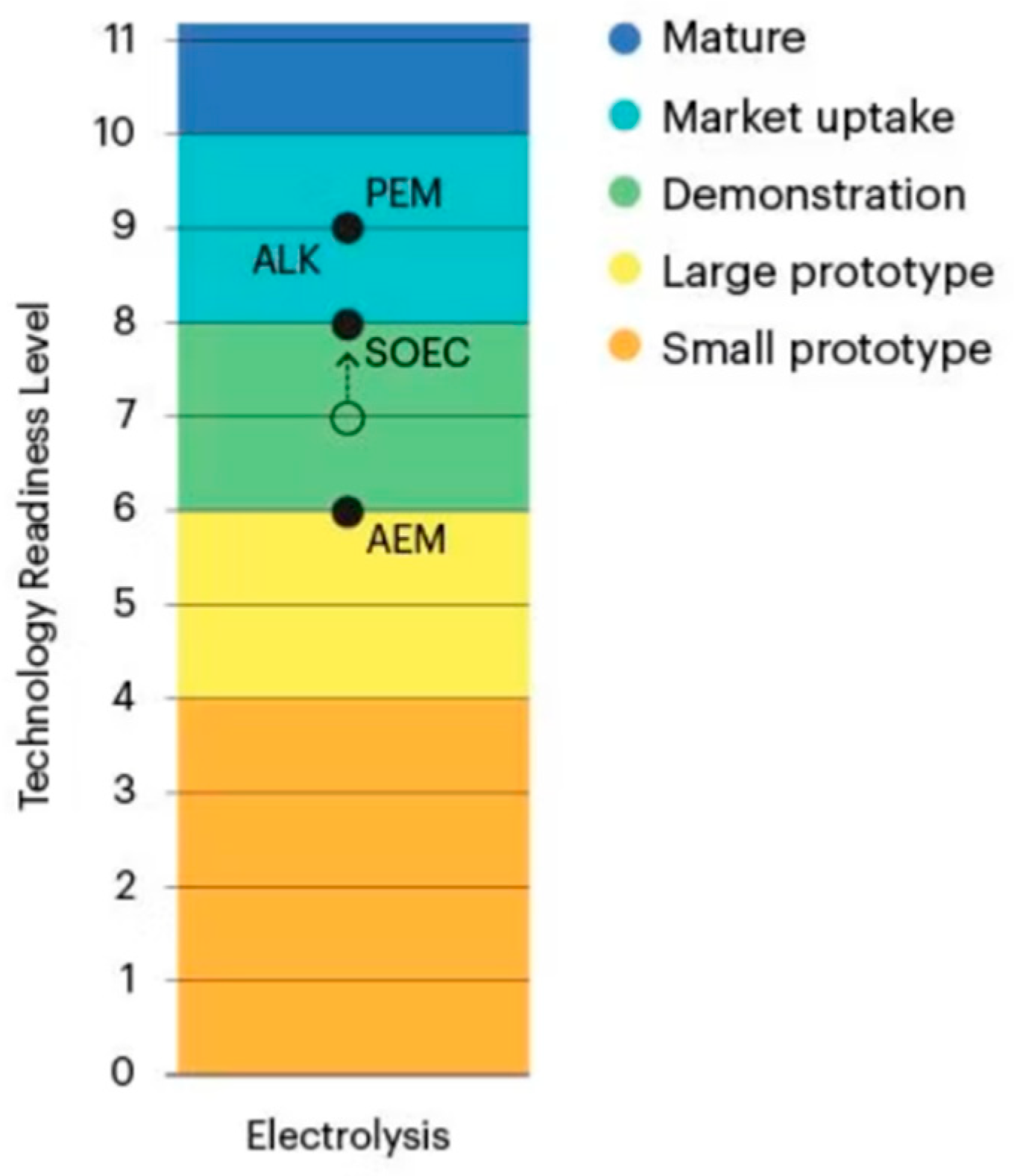
Figure 1. Types of electrolyzers with LTR indication [1].
Energies 17 05030 g001
Figure 2. Schematic illustration of a (a) membrane electrolyzer. General reaction pathways for HER and OER in (b) acidic and (c) alkaline solutions [2].
Energies 17 05030 g002
Figure 3. Volcano plot of exchange current density vs. ΔGH for various catalysts [2].
Energies 17 05030 g003
Figure 4. Polarization curves obtained from AEM water electrolyzer operation at 50 °C using MEAs with 20 wt% and 9 wt% PTFE binders in the anode and cathode, respectively (BC20), across the 10th (a), 50th (b), and 100th cycle (c) under varying cathode feed modes [5].
Energies 17 05030 g004
Figure 6. Schematic of experimental setup for water electrolysis: (1) Electrolytic cell (AEM electrolyzer), (2) Electric heaters for the cell, (3) Tube-in-tube heat exchanger, (4) Dew point meter (wrapped with heat tape), (5) Pre-mixing tank, (6) Flowmeter, (7) Control valve, (8) Circulation pump, (9) Accumulators (liquid–gas separator), (10) Cold traps, (11) Soap film flowmeter, (12) Digital flowmeters, and (13) Gas chromatograph (GC) [12].
Energies 17 05030 g006
Figure 7. Cell voltage (VCELL) and cell resistance (RCELL) as a function of current density (I) during electrolysis (upwards) using different electrolyte solutions (EL1–EL4) at cell temperature (TCELL) of 50 °C.
Energies 17 05030 g007
Table 1. Electrolyte solution and catalyst layer specifications for each electrolysis test [12].
NotationElectrolyte SolutionCatalyst Loading
SoluteConcentrationpHAnode (CuCoOx)Cathode (Pt)
EL1DI waterDI water10.84.2 mg cm−21.8 mg cm−2
EL2K2CO30.1 wt% (7.2 mM)10.84.2 mg cm−21.7 mg cm−2
EL3K2CO31.0 wt% (72 mM)11.34.0 mg cm−21.7 mg cm−2
EL4K2CO310 wt% (720 mM)11.84.1 mg cm−21.7 mg cm−2
EL5KOH10 mM12.04.1 mg cm−21.7 mg cm−2
Table 2. Description of different water-feeding methods for AEM water electrolysis [9].
SampleFeed TypeElectrodes
Initial FeedOperating FeedBinder Content wt%
Anode OERCathode HERAnode OERCathode HERAnode OERCathode HER
F10.5 M KOHDI water0.5 M KOHDI water209
F20.5 M KOHDI water0.5 M KOHNone
F30.5 M KOH0.5 M KOH0.5 M KOHDI water
F40.5 M KOH0.5 M KOH0.5 M KOHNone
BC50.5 MDI water0.5 MNone59
BC9KOH KOH 99
BC15 159
BC20 209
Table 3. Review of available knowledge of AEM cell technology.
Parameters\SourceNo[8][22][18][18][18]
materialanodesurface1 7.4 cm2
thickness2
conductivity3
porosity4
material520% platinum on carbon surface 0.5 mg/cm2CuCo-oxide on nickel foam + IrO2 catalyst in the amount of 4 mg/cm2 on nickel PTFE foam5% Nafion as an ionic binder with a nickel channelform of NiFe2O4 on nickel fiber paper5% Nafion as an ionic binder with a nickel channel
electrolyte/membranesurface6
thickness7
conductivity80.32 mS/dm
porosity9
material10 AEM anion-exchange membrane, X37-50 grade T KOH electrolyte in various concentrations
cathodesurface11 4.9 cm2
thickness12
conductivity13
porosity14 40% wt
material1520% platinum on carbon surface of 0.5 mg/cm21 mg/cm2 of Pt/C, on carbon-coated paper5% Nafion as an ionic binder with a nickel channelNiFeCo on stainless steel fiber paper5% Nafion as an ionic binder with a nickel channel
thermal flowtemperature1620 °C45 °C20 °C
working pressure171 atm 1 atm
flowanode18water KOH 3–5 mL/mindeionized waterKOH 3–5 mL/min
cathode19100 mL/min Nitrogen KOH 3–5 mL/min KOH 3–5 mL/min
experimental dataU-I curve20++
EIS21+ +
Table 4. Review of available knowledge of AEM cell technology.
L.P.[6][9][25][25][25]
1100 m2/g2.5 cm × 2.5 cm5 cm25 cm21.8 cm × 1.8 cm.
2 the thickness of catalyst layer 4.79, 10.11, 12.52 µmthe thickness of catalyst layer 4.79, 10.11, 12.52 µmfinal thickness of the electrode was 0.75 mm on 1.7 mm nickel foam
3
40.35 cm3/g
5ACTA 3030, Cuco Ox, synthesized by co-precipitation of
Co (NO3)2·6H2O and CuSO4·5H2O
IrO2 (Premion®, Alfa Aesar, Haverhill, MA, USA) + polytetrafluoroethylene (PTFE) binder
(60 wt% PTFE dispersion in H2O, Aldrich)
The 40 wt% Pt/C with iridium oxide (IrO2) with a loading amount of 1.0, 2.0, 3.0 mg cm−2 (Premion®, Alfa Aesar, USA)The 40 wt% Pt/C with iridium oxide (IrO2) with a loading amount of 1.0, 2.0, and 3.0 mg cm−2 (Premion®, Alfa Aesar, USA)NiO, NiFeOx, and NiFeCoOx catalysts deposited on the nickel foam (thickness of 1.7 mm), amount of 25 mg/cm2
6
728 micro m (in dry form) 50 µm30 µm
812 mS/cm (HCO3 form) 1.70 mohm/cm21.30 mohm/cm2
9
10Membrane: A-201 from Tokuyama Corporation, Electrolyte: diluted carbonate/bicarbonate aqueous solution, such as 1 wt% K2CO3 or 1 wt% K2CO3/KHCO3 (0.67% and 0.33%, respectively)A201, TokuyamaFAA-3 (Fumatech Co., Bietigheim-Bissingen, Germany)Orion TM1 (Orion Polymer, Cohoes, NY, USA)Fumasep
FAA-3-50 or dioxide membrane X-37-50 grade T), soaked in
a 1.0 M KOH solution overnight (about 24 h) and rinsed with distilled water
11180 m2/g2.5 cm × 2.5 cm5 cm25 cm21.8 cm × 1.8 cm.
12 250 μm thick titanium papers
13
140.59 cm3/g
15ACTA 4030, nickel-based nanostructured
material with the transition metal deposited on CeO2-La2O3/carbon
support
Pt/C (Pt 46.5 wt%, Tanaka K.K.), PTFE contents of 5, 9, 15, and 20 wt% (with respect to the total
solid weight) were used, and 250 μm thick titanium papers
The 40 wt% Pt/C with 0.2, 0.4, and 0.6 mgPt cm−2 of metal loading amountThe 40 wt% Pt/C with 0.2, 0.4, and 0.6 mgPt cm−2 of metal loading amountPt/C (40 wt%, HISPEC 4000, Johnson Matthey, London, UK) catalyst was
used for HER at the cathode, and 1 mg of Pt was deposited using drop casting method on
the carbon paper (Sigracet 29BC) which has a thickness of 235 micro m
16 50 °C50/60/70/8050/60/70/8045–70 °C
17
18H2O 1 M of KOH 1 mL/min1 M of KOH 1 mL/min90 mL/min
19 1 M of KOH 1 mL/min1 M of KOH 1 mL/min
20+ +++
21+/- +++
Table 5. Review of available knowledge of AEM cell technology.
L.P.[17][12][31][29][18]
1 25 cm2 = 50 mm × 50 mm 5 cm2
2 Ni-foam-1.4 mm was rolled to a 300 µm thickness using a slip-roll machine 0.25 mmvaried between 100 and 1700 nm
3
4 pore volume of 0.35 cm3/g−1, Ni-foam-0.96 (before slip roll), 0.84-after 75%
5NiO-synthesis procedure included (Ir as reference). The catalyst loading was kept equal to 5 mg/cm2 for all catalystsCuco Ox (catalyst loading 4.0 to 4.2 mg cm−2) +Ni foam as CC nickel felt (BEKAERT) and immersion in 4 M hydrochloric acid solution for 10 min at room temperaturecopper–cobalt mixed oxide films deposited on carbon paper (CP, TGP-H-90, Fuel Cell Earth) gas diffusion layer (GDL). An optimum Co/Cu atomic ratio of 1.8. Catalyst loads of 0.04 and 0.68 mg cm−2
6
7 28 µm50, 15, 20, 50, 75 µm
8 ion-exchange capacity (IEC) was 1.7 × 10³ mol/gIEC-0.92, 2.35, 2.20, 1.62, 1.65–2.18, 1.23–1.44 mmol/g
9
10Nafion (5 wt%, Alfa Aesar) or Fumion FAA-3 (10 wt%, Fumatech, full cell store) N2-saturated alkaline 1 M KOH electrolyteAEM (A201, Tokuyama) Fumasep FAA3-50, FAA-PK-75 (Bietigheim-Bissingen, Germany), PiperION 15, PiperION 20 (College Station, TX, USA), Nafion 212, and Orion Polymer’s TM1. All were immersed in 0.5 M NaCl solution for 24 h, followed by immersion in DI water for 24 h to remove any excess saltselectrolyte–potassium hydroxide (KOH, 85%, VWR), AEMION™ AEMs submerged in 1 M of KOHFumapem® FAA-3-50 supplied by Fuel Cell Store
11 25 cm2 = 50 mm × 50 mm 5 cm26.25 cm2
12 0.25 mm
13
14 75%
15Ni/C-synthesis procedure included (Pt/C as reference). The catalyst loading was kept equal to 5 mg/cm2 for all catalystsPt/C (TEC10V50E, TKK), Pt loading at about 1.7 mg/cm2 nickel felt (BEKAERT) and immersion in 4 M hydrochloric acid solution for 10 min at room temperaturenanostructured metallic Nickel films deposited on carbon paper GDL supports
16ambient50 °C30–6060 Croom temperature, 30–70 °C, 40 °C
17 ambient
181 mol dm3 of KOH solution was circulated at each side of the AEMWE, respectively, at 50 cm3/minelectrolyte solution K2CO3, DI water 0.1 wt% (7.2 mM), pH 10.8, 20 mL/min 1 M of KOH. A two-channel peristaltic pump (Watson-Marlow) at 10 rpm, equivalent to 2 mL min−11.0 M of KOH electrolyte solution flow rate of 2 mL min−1
191 mol dm3 of KOH solution was circulated at each side of the AEMWE, respectively, at 50 cm3/min- 1 M of KOH. A two-channel peristaltic pump (Watson-Marlow) at 10 rpm, equivalent to 2 mL min−11.0 M of KOH electrolyte solution flow rate of 2 mL min−1
20 + +
21+ +
L.P.[32][28][19][33][5]
15 cm25 cm2, electrolyzer-4 cm21 cm24 cm25 cm2
2
3 440 S·m−1 at 4 MPa
4
5NiFe2O4 on nickel fiber paperFC:PtRu/C (Johnson Matthey, 60 wt%, 0.2 mg cm−2), electrolyzer-CoFeP TPA powder (2.0 mg cm−2) was mixed with QPPO ionomer Co-Ni-P/NFplatinized anticorrosion sintered titanium particles were used as the anode PTL, synthetic NiFeCo was used as the anode catalystIrO2 (Surepure Chemetals, Florham Park, NJ, USA)
6
750 µm, 38 µm, and 28 µm, respectively20 µm75 µm 50 µm
8 160.5 mS cm−1
9
10Sustainion, AEMION, and A-201cPVBMP-3.0 Coppo membraneFAAM-75-PK; Fumatech, 1.0 M NaOH was used as a single electrolyteQAPPT, immersed in 1 M of KOH solution for 24 h to replace Cl− with OH− and then washed several times with deionized water until the washing water was neutralFAA-3-50 (Fumatech, Germany) was soaked in 1 M of potassium hydroxide (KOH) solution for 1 h and then rinsed with deionized water
115 cm25 cm2, electrolyzer-4 cm21 cm24 cm25 cm2
12
13
14
15NiFeCo on stainless steel fiber paperFC-Pt/C (Johnson Matthey, 60 wt%, 0.2 mg cm−2), or FeNx-CNTs37 (4 mg cm−2), Electrolyzer-Pt/C (Johnson Matthey, 40 wt%)Co-Ni-P/NFCarbon paper was used as the cathode porous transport layer (PTL), 60 wt% Pt/C40 wt% Pt/C
1640, 50, 60 °CFC-80 °C, Electrolyzer-60 °C 8050, 60, 70
17 FC-0.2 MPa backpressure
183–5 mL min−1, 0.1 M, 0.5 M, and 1 M of KOHFC-pure H2, 1 L min−1, and 100% RH, electrolyzer-DI waterFor commercial electrolyzer, 1.0 M of NaOH, 12.5 mL/min DI water or KOH solution, 1 or 2.5 mL/min
193–5 mL min−1, 0.1 M, 0.5 M, and 1 M of KOHair (CO2-free), 1 L min−1, and 100% RHFor commercial electrolyzer 0.5 M of H2SO4, 12.5 mL/minpure waterDI water or KOH solution, 1 or 2.5 mL/min
20+++++
21 ++
Table 6. Review of available knowledge of AEM cell technology.
L.P.[24][4][30][26]
17.4 cm2 5 cm25 cm2
2 foam thickness is known
3
4
5NiFeV layered double hydroxide (LDH) nanosheets supported on the Ni surface by corroding a Ni foam (NF) electrodeIridium oxide (IrO2, Premion1, Alfa Aesar), Titanium paper (250 mm, Bekaert)Ni2P−Fe/NF, NF ranging from 220 to 800 μm, or IrO2Ti-felt, Ni-felt, and Ni-foam, Ni-Fe alloy black (Sigma Aldrich Co., USA), 1 mg metal cm2
64.9
7 75 µm25 µm50 µm
8
9 46%
10AEM, X37-50 grade T, Dioxide Materials/50 mL min−1 in 1 M KOHFAA-3-PK-75PE(VBTAC), PFT-C6-TMA ionomerFAA-3-50 membrane (Fumatech Co., Germany) immersed in a 1.0 M of KOH solution at room temperature for 3 h and rinsed with deionized (DI) water, ionomer (FAA-3-Br, Fumatech Co, Germany)
114.9 cm2 5 cm2
12
13
14
15Pt/C platinum on carbon (Pt/C, Pt 46.5 wt%, Tanaka K.K), carbon paper (TGP-H-120, Toray)Pt/CA carbon-based PTL (JNTG40-A3, JNTG Co., Republic of Korea) was used as the cathode PTL, 40 wt% Pt/C (Johnson Matthey Co., Wayne, PA, USA) was used at the cathode, 0.4 mg of metal cm2
165050, 60, 70, 80, 908070
17 pressing time was controlled (0, 1, and 3 min) at 50 °C and 395 psi
181 M KOH0.5 M of KOH 1 mL/min 1 M of KOH aqueous solution or pure water, 5 mL/min1.0 M of KOH solution at 60 °C with a flow rate of 5 mL/min
19 1.0 M of KOH solution at 60 °C with a flow rate of 5 mL/min
20++++
21++++
Disclaimer/Publisher’s Note: The statements, opinions and data contained in all publications are solely those of the individual author(s) and contributor(s) and not of MDPI and/or the editor(s). MDPI and/or the editor(s) disclaim responsibility for any injury to people or property resulting from any ideas, methods, instructions or products referred to in the content.