Article

A Digital Iterative Learning Based Peak Current Mode Control for Interleaved Totem Pole PFC Circuit

by
Ahmet Talha Dudak
1,2,* and
Ahmet Faruk Bakan
2
1
Department of Power and Control Systems Design Engineering, ASELSAN, 06200 Ankara, Turkey
2
Department of Electrical Engineering, Yildiz Technical University, 34220 Istanbul, Turkey
*
Author to whom correspondence should be addressed.
Energies 2024, 17(20), 5026; https://doi.org/10.3390/en17205026
Submission received: 20 August 2024 / Revised: 16 September 2024 / Accepted: 4 October 2024 / Published: 10 October 2024
(This article belongs to the Section F3: Power Electronics)

Abstract

:
Iterative learning based digital peak current mode control (PCMC) is proposed in this paper. The proposed control method provides excellent current reference tracking against variations in input voltage, load, and circuit parameters. Compared to other current control methods, the proposed digital PCMC has a high dynamic response, a simple structure and a low computational burden. It is suitable for power factor correction (PFC) converters operating at high frequency. Thanks to the iterative learning control (ILC), the peak current value in PCMC is successfully compensated against disturbances. The proposed new current control method is applied to an interleaved totem pole PFC (ITPPFC) circuit. The ITPPFC circuit prototype is implemented with 250 W output power and 100 kHz switching frequency. The circuit prototype is tested under various load conditions and parametric disturbances. Theoretical and experimental results are found to be consistent.

1. Introduction

Minimizing problems such as power loss, noise, and grid current distortion is important to comply with international standards such as IEC 61000-3-2, 80 Plus, and Energy Star [1,2,3]. To overcome these problems, PFC circuits are widely used in the industry. Thanks to the PFC, it is possible to design a converter with low THD and unity power factor (PF) in compliance with international standards. To achieve unity PF and low THD, accurate reference current tracking is critical. Non-idealities and variations in the current control can be classified as boost inductance value varying with current, non-sinusoidal grid voltage, parasitic effects of active and passive components, difficulty with current prediction in DCM operation, and zero-crossing distortions.
The most commonly used control method in the PFC circuits is the average current mode (ACMC) control. In this control method, an outer loop voltage controller is designed for the output voltage control and an inner loop current controller is designed for the input current control [4,5,6,7,8]. In the case of using PI controller, the reference current tracking is not exactly accurate. It is also inadequate in terms of dynamic response. Variable load conditions, non-sinusoidal grid voltage, varying circuit parameters, and digital time delays adversely affect the performance of the conventional ACMC and the THD of the input current deteriorates.
The predictive current control (PCC) method can provide improvements for more robust control performance compared to conventional ACMC. In conventional PCC, the duty cycle is predicted by considering the system model [9,10,11]. However, the non-idealities are not considered in these methods. There are many studies focusing on improved digital PCC with more efficient performance to deal with variations and non-idealities [12,13,14,15,16,17,18,19,20,21,22]. In [12], a digital PCC is proposed for valley current control, PCMC and ACMC methods. The method is performed by considering the effect of inductance variation, but parasitic effects and distortions in DCM operation are not considered. In [13], a study analyzing the transitions between CCM and DCM operation has been performed. In the DCM operation, the effect of oscillation between the parasitic capacitance of the semiconductor switches and the boost inductor is analyzed. This parasitic effect causes inaccurate current prediction and distorts the current waveform. In [13], this parasitic effect problem is solved by RC snubber. However, this solution causes additional power loss for the circuit. In [14], a nonlinear current control method is proposed to overcome the limitation of control bandwidth in ACMC. The voltage loop is implemented digitally, while the current loop is analog. In [15,16,17,18,19,20], a control is performed to compensate the distortion effects in the DCM operation. In [18], although the variation in the inductance value is considered, it does not provide a solution for other non-idealities. In [19], a PCC method is performed by detecting CCM and DCM operation transitions. In [19], frequency modulation is performed to solve the DCM distortion problem. In [21], the partial-switching PCC method is proposed. In [22], a pulse train control strategy is proposed to improve dynamic response. Consequently, none of these studies has proposed a solution that covers all non-idealities.
There are advanced studies to improve control performance in conventional PCC [23,24,25,26,27]. In [23], the controller gains are determined by using two digital tuning algorithms for the voltage and current loops. By detecting CCM and DCM operation transitions, stable operation of the controller in both CCM and DCM is desired. However, this method still does not prevent input current distortion. Due to the oscillations in DCM operation, the quality of control is reduced because the current cannot be measured properly. In [24], a compensation method in the synchronous reference frame is proposed to improve the dynamic performance. However, the method imposes a severe digital computational burden. In [25], a PCC method is proposed by detecting CCM and DCM operating modes. The current distortion caused by oscillation in DCM is decreased, but this decrease requires extra computational burden. Besides that, the effects of all non-idealities are not included. In [26], a method is proposed to correct the current distortion caused by the parasitic effect in DCM. However, the method requires complex mathematical operations. In [27], a new deadbeat PCC method is proposed. The problems such as non-sinusoidal grid voltage, parametric variations and control delays are considered. However, the current reference tracking is still not accurate enough.
There are studies on control methods for high accuracy tracking of the input current reference in PFC circuits [28,29,30,31,32]. In [28], a new current ripple compensation technique is implemented by replacing the linear slope compensation in PCMC with a parabolic compensation technique. The proposed circuit requires many analog components and has a complex circuit structure. In [29,30,31], the tracking control is performed by the repetitive control method. These studies have been applied to ACMC. In [29], an additional compensation is required for DCM operation. In [30], it is seen that the current waveform is distorted at low loads. In [31], a controller parameter optimization for a three-phase PFC circuit is performed with a genetic algorithm. However, the dynamic response is not sufficient in all of these studies. In [32], a tracking control method is proposed for ACMC. However, there is a trade-off between computational burden and input current waveform accuracy in this study. If the computational burden is reduced, a low-frequency oscillation arises in the input current waveform. It is necessary to reduce the computational burden at high-switching frequencies, but, in this case, the input current waveform will be distorted. In addition, this study does not consider DCM operation.
In ACMC, the slope of the inductor current in one switching period is critical for the accuracy of the current value sampled in the middle of the PWM. If the slope is high, the sampled current will be less accurate than the average current due to sampling delays. Therefore, it is useful to choose an inductance value that provides low current ripple in the ACMC. In addition, ACMC requires the design of a current controller. The PCMC is an analog-based control method, and the peak value of the current is directly controlled. Thus, a controller design is not required. The PCMC has a good dynamic response and provides protection against overcurrent. It is also suitable for high frequency applications. Some studies have been performed to highlight the advantages of PCMC [33,34]. In [33], the peak value of the current is determined by prediction and used to control the inductor current. However, it requires extra computational burden for non-idealities. In [34], a PFC circuit is designed with a 1 MHz switching frequency. In this application, PCMC is used to achieve a fast control with a high switching frequency. It has a variable switching frequency according to the DCM and CCM operating modes.
In [35], a PCC method is used to solve the problems caused by non-idealities and variations in the totem pole PFC circuit. This PCC does not include the input current sensor. However, the method requires a PI controller design for the current control. Moreover, the method presented to reduce the noise of the sensed voltage causes a deterioration of the dynamic response. In addition, in totem pole PFC circuits, current spikes occur in the zero crossings of the grid [36]. In the current control with PI controllers, the process of tracking the current reference in zero crossing regions is not fast and precise. This distorts the input current waveform and causes high THD. It is also necessary to take precautions against this situation.
Many studies have been carried out to solve the control problems that arise depending on the system model [37,38,39,40,41,42,43,44,45,46]. These studies can be called model-free control methods. Model-free control methods do not require a detailed mathematical model of the system. Model-free control is performed for many control methods such as data-driven control [37,38], reinforcement learning [39], extremum seeking control [40], fuzzy control [41,42], neural network [43], ILC [44,45,46], etc.
The ILC can be used to solve the real time control problems. It is an effective and simple control method for real-time control systems, for example, robotic systems, batch reactors, electrical drives [44,45], aerodynamic systems, bioengineering systems, and others. The ILC improves the system response iteratively. It has excellent reference tracking, a model-free design and delay compensation. In practical applications, a simple controller is preferred due to issues such as implementation effort, control quality and reliability. For single-input, single-output systems, setting only one learning gain is sufficient in ILC. The ILC is performed by using the past tracking errors and past control signals during the whole operation period. The ILC is a memory-based learning controller and can be implemented easily and cheaply with the microprocessors. Unlike many control methods that require system model information, the ILC requires no model information except a global Lipschitz condition. This property is desirable for real-time control systems because modeling the system accurately is a very difficult process. Also, the ILC can easily compensate the sampling time delay in feedback loops using the signals of the previous iteration thanks to its memory-based structure.
In this paper, the ILC method is implemented for a simple and robust control against unmodeled circuit parameters and variations in the PCMC. The control signal derived from the ILC is added to the average current value of the boost inductors derived from the ideal circuit model to achieve a compensated peak current value against disturbances and parameter variations. The proposed control method does not require the information of the non-ideal circuit parameters and variations. The proposed control method provides an excellent current reference tracking and does not require a current controller. Since the PCMC is analog, the combination of the ILC with the PCMC provides a very fast dynamic response. In addition, the proposed PCMC can be easily implemented by using analog subsystems in the digital signal processor (DSP) without additional components.
This paper is organized as follows. In Section 2, the average input current prediction is performed with ideal circuit parameters. Non-idealities and disruptive effects are explained. Section 3 presents the analysis of the proposed ILC method. Section 4 discusses the experimental results of the ITPPFC for the different loads and parametric variations. Section 5 concludes the paper.

2. Digital PCMC in Interleaved Totem Pole PFC

The proposed control method is shown in Figure 1. The vac, iac, iL, iL1 and iL2 represent the grid voltage, the grid current, the unfiltered input current, and the L1 and L2 inductor currents, respectively. The Lf and Cf are the input filter inductor and capacitor, respectively. The G1, G2, G3, G4, G5 and G6 are the gate signals of the T1, T2, T3, T4, T5 and T6 switches, respectively. The Cdc is the output capacitor, vdc is the output voltage and idc is the output current. The PFC circuit includes three half bridges. The HF1 and HF2 half bridges operate at switching frequency. The LF bridge operates at grid frequency. When vac is positive, T6 is on. In this interval, T2 is switched at high frequency. When T2 turns on, the L1 inductor is exposed to the vac and iL1 increases. When T2 turns off, the energized inductor transfers its energy to Cdc. In this interval, the PWM signal of T1 can be applied to decrease the conduction loss of D1. When vac is negative and when T1 turns on, the inductor current increases in the negative direction. When T1 turns off, the energized inductors transfer their energy to Cdc. When vac is negative, the switch T5 is active. There is a 180° phase shift between HF1 and HF2 half bridge PWM signals. The main features of the proposed digital PCMC method are presented as follows:
  • The ILC method is used to minimize the error between the predicted average current and the reference current to ensure perfect reference tracking despite non-idealities and variations. The output of the ILC is added to the average current value calculated for the PCMC in each phase leg to achieve the compensated peak current value.
  • The compensated peak current value is loaded into the digital-to-analog converter (DAC) and cycle-by-cycle current control is performed using fast comparators in the DSP.
  • The outer voltage controller is not performed to analyze the performance of the proposed current controller. The grid synchronization of the input current is performed with the digital phase locked loop (PLL) algorithm.

2.1. Average Input Current Prediction

The PFC converters can operate in different operating modes such as CCM and DCM. In CCM operation, where the inductor current is not zero during a switching period, the MOSFET switching loss is high due to hard switching, while the inductor core losses are low compared to other operating modes due to low inductor current ripple. In DCM operation, turn on switching losses are reduced, while core losses are increased due to high inductor current ripple.
In digital current control methods, when the current is sampled in the middle of the PWM, the sampled value is ideally equal to the average current value for CCM operation. In DCM operation, the current value sampled in the middle of the PWM is not equal to the average value. In conventional digital applications, to accurately sample the average inductor current in DCM operation, it is necessary to take multiple samples in one switching period.
In the conventional digital ACMC method, the average value of the current is obtained with an analog to digital converter (ADC). The analog measurement circuit generally includes a low pass filter (LPF) and this causes measurement delay. Due to the bandwidth limitation of the PI controller, the reference tracking is not satisfactory. The proposed method predicts the average value of the current from the ideal model parameters. Non-idealities such as parametric variations and disturbances in the circuit are compensated by the ILC cascaded into the control.
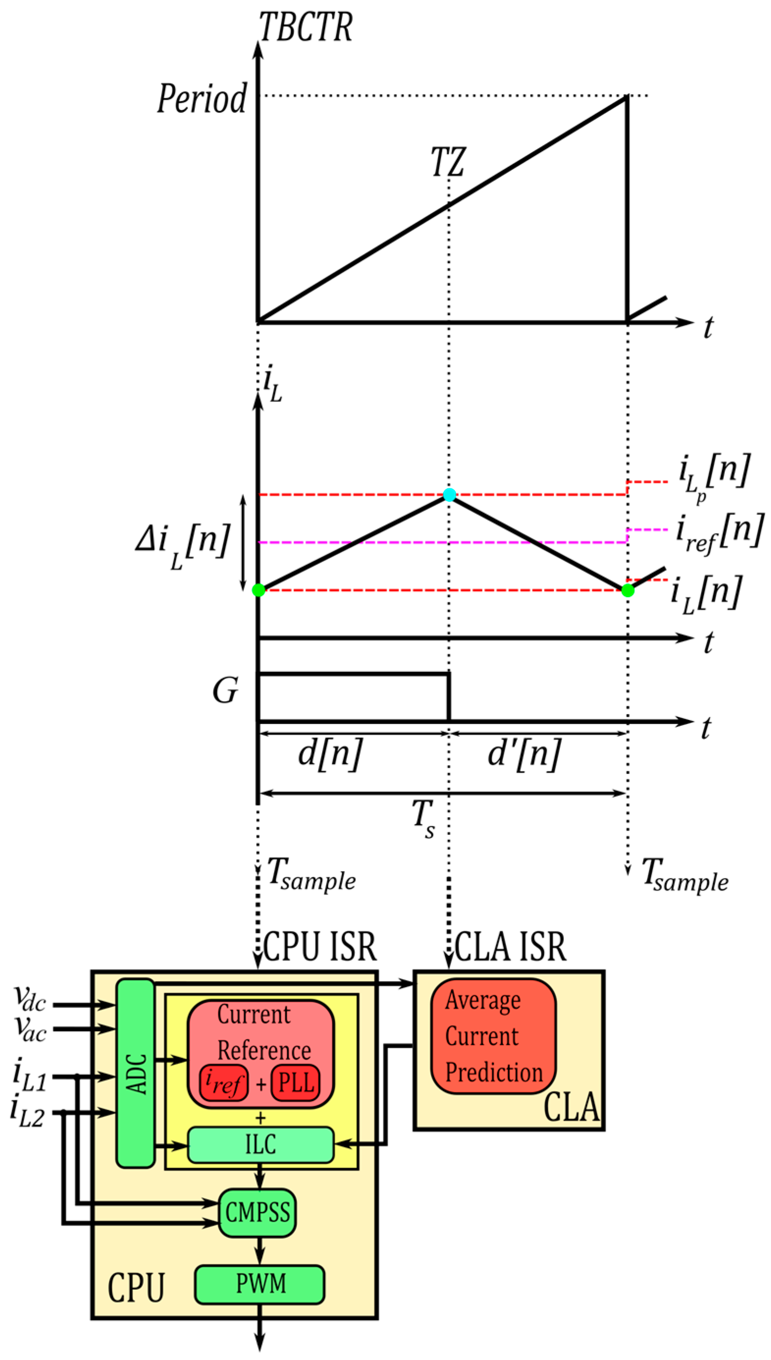
In the proposed method, the prediction process is performed as a result of the trip zone (TZ) interrupt generated by turning off the PWM signal in the PCMC. This TZ interrupt generates an interrupt to the control law accelerator (CLA) in the DSP with the CLA interrupt service routine (ISR). Other operations such as ILC, PLL, ADC, comparator subsystem (CMPSS) and PWM are performed by the main CPU inside the DSP. The interrupt for the main CPU is generated when the time base counter (TBCTR) of the PWM module in the DSP is zero. When TBCTR reaches the Period value, it returns to zero again. The CLA and CPU in the DSP operate together in parallel to reduce the computational burden. To predict the average current, the PWM duty cycle is obtained by using the TBCTR value at the TZ interrupt. Figure 2 shows the inductor current waveform and the block diagram for ISRs generated according to TBCTR.
In the analysis of the average current prediction, the equations for each phase leg of ITPPFC are the same. Therefore, there is no need to derive the equations separately for each inductor. In the conventional PCC methods, the duty cycle calculation includes a square root operation in DCM and this operation is time consuming for DSPs. In the proposed control method, the TBCTR value read at the TZ interrupt matches with the turn on time of the PWM signals. Thus, the average current can be calculated without complex operations such as square root.
The time base clock (TTBCLK) is determined according to the operating frequency of the DSP. The Period value of TBCTR can be selected according to the following equation for the switching period:
T s = P e r i o d + 1 T T B C L K
The TBCTR takes a value between the Period and “0”. If the TBCTR value is read when the TZ interrupt of the PCMC is generated, the required data for the turn on time of the PWM can be determined. In the CCM and DCM operation, the turn on time of the PWM value can be found in a similar way as follows:
d [ n ] T s = T B C T R t = T Z + 1 T T B C L K
Here, d n is duty cycle. In the ILC method, control data are stored in an n-dimensional array. The sampling point of the discretized signal in the switching period is indicated by the index n. According to the principle of volt-second balance of inductor, the d n is given as follows for the positive and negative of the grid voltage. Here d n is the duty cycle of the interval where the inductor transfers its energy to the output. Equations (3) and (4) are the generalized equations for CCM and DCM.
d n = v a c n v d c n v a c n d n   v a c > 0
d n = v a c [ n ] v d c n + v a c [ n ] d n   v a c < 0
The generalized equation for the calculation of the average inductor currents in a switching period can be given as follows. Here i L a v g n is a common representation for i L 1 a v g n and i L 2 a v g n .
i L a v g n = i L n + i L [ n ] d n + d [ n ] 2
The inductor current ripple equation i L n is also given as follows. In this equation, L is a common value for both inductors L1 and L2. Here, i L n is a common representation for L1 and L2 inductor current ripples.
i L n = v a c [ n ] L d n T s
If Equations (3), (4) and (6) are substituted in (5), (7) is derived for the positive of the grid voltage and (8) is derived for the negative of the grid voltage. In DCM operation, the value of the i L n term can be defined as “0”.
i L a v g n = i L n + v a c n d 2 n T s 1 + v a c [ n ] v d c n v a c [ n ] 2 L
i L a v g n = i L n + v a c n d 2 n T s 1 v a c [ n ] v d c n + v a c [ n ] 2 L
This average current prediction is a valid formulation for ideal situations. It is possible to perform the PCMC for the next PWM cycle with the peak current value determined by adding a current ripple to this average current value. However, this current control is not robust against non-idealities. The proposed ILC method performs the compensation against non-idealities. The disruptive effects of these non-idealities are discussed in the next section.

2.2. Investigation of Non-Idealities and Disruptive Effects

The load variations with unmodeled non-ideal parameters in the control system are problems for the ideal PCC. To overcome these problems, additional mathematical calculations are added to the control. As a result of this, the complexity increases. Since these trouble cases are repetitive, it is easy to compensate them with the proposed method. The following summarizes the effect of the non-idealities and variations.

2.2.1. Effect of Inductance Variation

The value of the inductance designed for a PFC circuit changes with its current. The magnetic permeability of the core decreases at high currents. To achieve perfect reference current tracking, the inductance variation must be compensated. In conventional methods, the negative effect of parametric variation is reduced by using extra mathematical equations, but it increases the controller complexity. The proposed method provides successful reference tracking without computational burden.

2.2.2. Difficulty of Current Prediction in DCM Mode

The DCM operation arises when the grid voltage is low or the output power is low. Closed loop systems with linear controllers designed for the CCM do not perform successfully in the DCM and it becomes difficult to track the reference current. In the DCM, mathematical operations involving square roots are required to predict the average current. This causes an additional computational burden on the processor and is a constraint for digital applications. This constraint is a problem for operation at high frequencies. In the proposed method, reference tracking can be easily performed in the DCM without the need for complex mathematical equations. Therefore, operation at high frequencies in time-critical applications can be achieved with no difficulty.

2.2.3. Zero Crossing Distortion

In conventional ACMC, the spikes in the input current waveform of the totem pole PFC circuits happen in the zero-crossing regions of the grid. This is because the controller cannot follow the current reference quickly and accurately. If no precautions are taken to prevent this, the THD value significantly deteriorates. To solve this problem, soft start is performed at zero crossing regions and this effect is minimized by gradually increasing the duty cycle. However, since the proposed method provides excellent current reference tracking, the controller is able to compensate for the zero-crossing distortions very quickly without any additional process.

2.2.4. Digital Computational Burden

In the digital current control methods, the processing load causes digital delays. The ADC operation and the calculations required for the average current prediction cause processing load. These processes need to be completed within one switching period. As the system becomes more complex, ADC operation and calculations take more time. In particular, operations such as square root and division can take significant time for the DSPs. This situation is a constraint for high frequency operation. In time-critical applications, it is necessary to consider this situation and take precautions against control complexity. As shown in Figure 2, the main CPU performs ADC, PLL, CMPSS, PWM and ILC while the CLA predicts the average current. Also, analog elements of the DSP are used for the PCMC to reduce the processing load on the digital side. Therefore, a very simple and fast control algorithm is performed and a suitable design for high switching frequency is achieved.

3. Analysis of the Proposed ILC Method

3.1. Implementation of the ILC Method for Digital PCMC

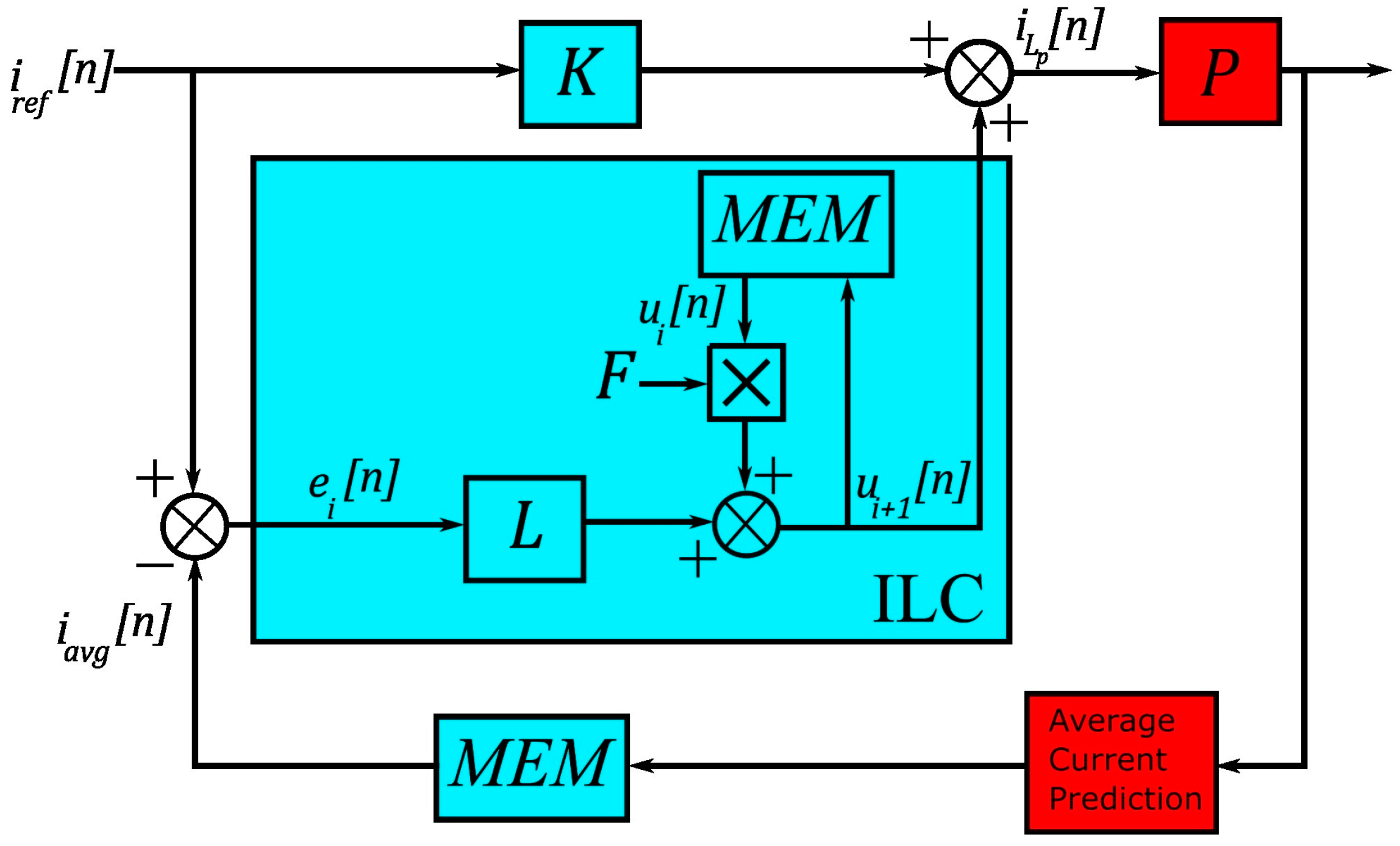
The ILC is a real-time control method that is characterized with simple structure, excellent reference tracking quality, parameter independence and robust control performance. The ILC does not require detailed modeling of the system. To perform ILC, the system needs to have a periodic behavior. Modeling error and disturbance effects can be compensated by ILC as long as the effects are repeatable. Figure 3 shows the block diagram of the proposed ILC method. The ILC is used as a plug-in controller to a conventional controller.
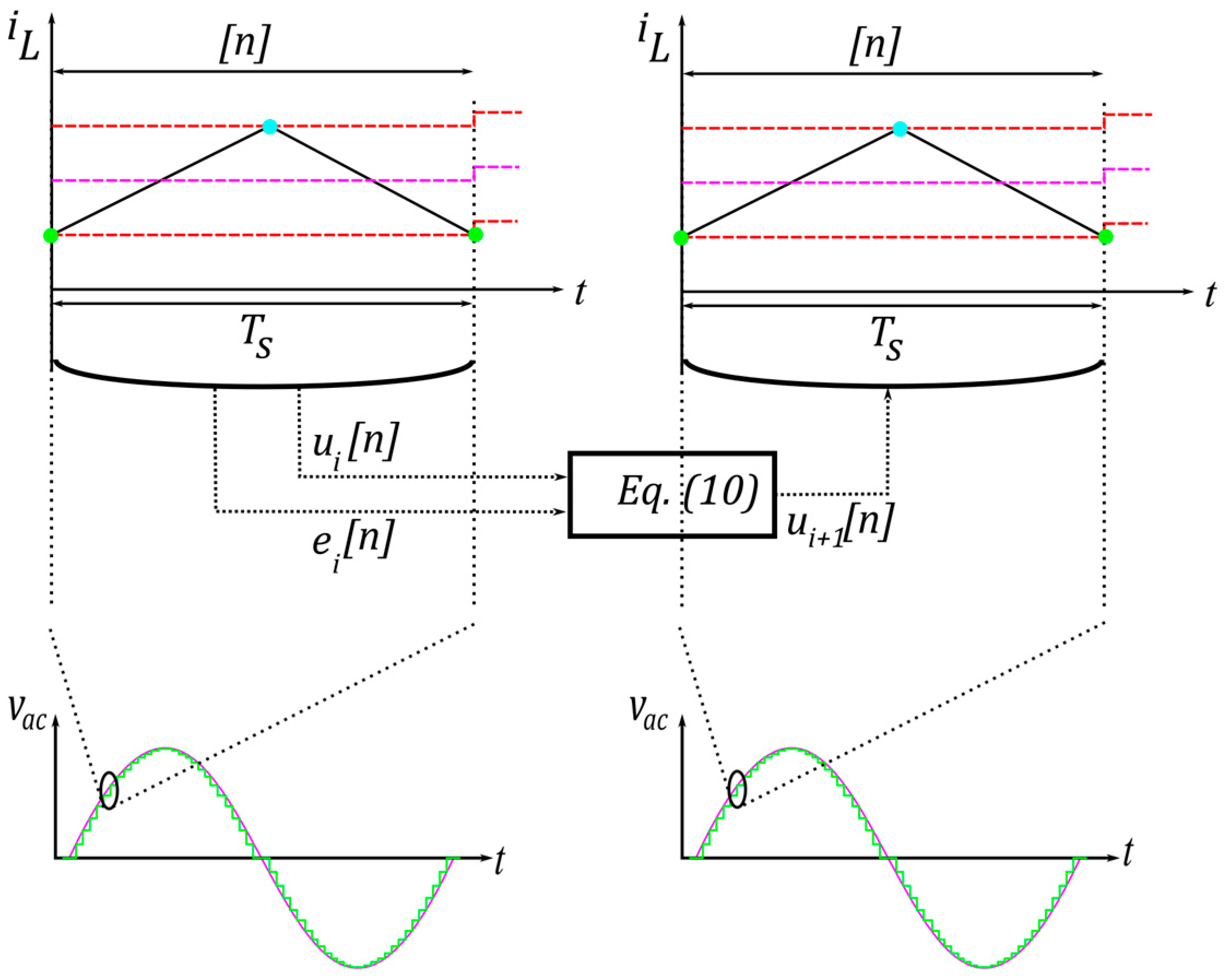
In accordance with the control method shown in Figure 3, the ILC output control signal ( u i + 1 n ) is added to the calculated average current value of the ideal circuit model to determine the peak current value in the digital PCMC. The learning law is formulated as in (10). The F is the forgetting factor variable, which is also called a filter. The u i n is the control signal used in the previous iteration. The L is the learning gain and constant. The i r e f n and i a v g n are the reference current and the predicted average input current, respectively. The i a v g n represents the sum of the inductor currents derived in (7) and (8). The e i n is the error signal between i r e f n and i a v g n . The P is the transfer function of the system. The MEM is the memory array and stores i a v g n and u i n signals for one iteration during the grid period. The iteration domain (i) is called the grid period, while the time domain (n) is called the switching cycle. Figure 4 shows the iteration and time domain with the learning law. The i is the number of iterations corresponding to the grid period.
e i n = i r e f n i a v g n
u i + 1 n = F u i n + L e i n
The learning law operates iteratively until the error between the predicted average input current and the reference current converges to zero. The compensated peak current value is calculated as in (11). Here, i L p n is a common representation for L1 and L2 inductor current peak. The term K represents the phase number of the ITPPFC.
i L p n = K i r e f n + u i + 1 n
In the other current control methods, the reason of the insufficient current reference tracking in current control is due to the designed controller. Due to non-idealities and variations, the controller cannot perform reference tracking effectively. The uncertainty structure in the system model should also be known for a successful tracking. However, it is very difficult to model the system with high accuracy.

3.2. Convergence and Stability Analysis of the ILC

As shown in Figure 3, a learning law is given as in (12). The i r e f L represents the reference current for each phase in ITTPFC. The proposed ILC has an incremental learning structure. The advantage of the incremental structure is that the reference signal is not affected by the filtering process. The ILC is incrementally cascaded to the reference signal and the filter applied to the control signal of the ILC does not distort the reference signal.
i L p , i + 1 = i r e f L + u i + 1
In (12), u i + 1 can be expressed as follows and u 0 is equal to “0”:
u i + 1 = u i + L e i
When the number of the iteration increases, the error converges to “0”. The incremental learning in cascade ILC is derived as follows:
i L p , i + 1 =   i r e f L + u i + 1 =   i r e f L + u i + L e i = =   i r e f L + j = 0 i L e i j
In the ILC, the repeatable perturbation can be entirely eliminated, but the measurement noise and disturbances, which are not repetitive and affect the performance, cause an increasing learning error and cannot be eliminated. The filtering is used against the non-repetitive perturbations or measurement noise. The filtering applies to previous tracking errors. When we add a filter to the controller, the incremental learning changes as follows:
i L p , i + 1 =   i r e f L + u i + 1 =   i r e f L + F u i + L e i =   i r e f L + F 2 u i 1 + j = 0 1 F j L e i j = =   i r e f L + j = 0 i F j L e i j
If the errors e 0 ,   e 1 ,   ,   e i are all zero, i L p , i + 1 is equal to i r e f L . However, this is practically impossible. Due to the inductor current ripple and other non-repetitive signals, there is always a non-zero control signal cascaded to the reference current value.
In practical applications, the tracking error decreases during the first few iterations. However, it increases when the iterative learning continues. This situation is caused by the non-repetitive factors. The control system includes both repetitive and non-repetitive signals. If a precaution is not taken, the non-repetitive signals could be dangerous for the ILC. These non-repetitive signals cause error accumulation when the number of iterations increases. The error signal of the ILC is derived as follows, taking into account an external disturbance or noise ( D i ):
e i + 1 =   i r e f i a v g , i + 1 =   i r e f P u i + 1 D i + 1 =   i r e f P u i + L e i D i + 1 = 1 P L e i D i + 1 D i
If D i + 1 is equal to D i , this is a repetitive perturbation and ILC can eliminate it. The ILC is unable to eliminate the non-repetitive perturbations. In this case, the error signal is derived as follows:
i = D i + 1 D i
e i + 1 = 1 P L i + 1 e 0 + j = 0 i 1 P L i j j
In the first few iterations, the tracking error is reduced by the attenuation of the initial error 1 P L i + 1 e 0 . The accumulation of 1 P L i j j causes the error increment, when the number of the iteration increases.
To solve problems caused by the undesirable non-repetitive factor, the filter is commonly used in practice. The error signal is derived as follows:
e i + 1 =   i r e f i a v g , i + 1 =   i r e f P u i + 1 D i + 1 =   i r e f P F u i + L e i D i + 1 = F P L e i D i + 1 F D i 1 F i r e f
The convergence is determined by F P L . The F can be assumed as an LPF. Choosing a lower value of F makes the control robust, while the learning effect is weakened. For the first iterations, F is set to 1 and D i is negligible. As the number of the iteration increases, F is chosen to be less than 1. The recommended first F value is in the range [0.95, 0.99]. For i , F converges to “0”. Butterworth LPF is used to adjust the forgetting factor effectively. The frequency response of the Butterworth LPF is given in (20).
F j ω 2 = 1 1 + j ω / j ω c 2 N
In (20), N is the order of the filter. The ω c is the cutoff frequency. The LPF has the pass band at ω = 0 and the stop band at ω . In practical applications, the Butterworth LPF is chosen as the second order LPF. If the N chosen is higher order, the stop band property can improve, but the phase lag increases and the learning process is weakened [47].
The convergence condition is given in (21). If the L chosen is low, the learning rate slows down. On the other hand, if the L chosen is high, it can cause an oscillation in the control system.
F P L < 1 0 < L < 1 + F P
In (21), P corresponds to the ratio of the average average current value to the inductor ripple current value. The maximum value of P determines the maximum allowed learning gain. For the ITPPFC, the maximum average current is the inductor saturation current and its value is 8 A. The minimum inductor ripple current is 0.4 A for the minimum duty cycle. Also, if F is assumed equal to “1”, the range of the learning gain is obtained as follows:
0 < L < 0.1
In Figure 5, the convergence is shown for different learning gain. If the learning gain chosen is very low as in Figure 5a, the error signals remain the same from the first iteration to the 20th iteration, and convergence is not achieved. If the learning gain chosen is very high as in Figure 5c, the error takes extremely high values and dangerous oscillations arise. Hence, a suitable learning gain is required for successful learning and stability of the system. In Figure 5b, it is seen that the learning process is performed successfully. The error signals converge to zero as the number of iterations increases.
The effect of the disturbances is shown in Figure 6. The disturbances such as non-idealities, variations, and measurement noise have a negative impact on the control system. In practical applications, the circuit parameters can change depending on the time. For instance, the inductance value changes according to the temperature and its current value. In most predictive current control methods, since the inductance value is used in the mathematical model of the control system, the incorrect inductance value causes the undesired cases. Therefore, unmodeled circuit parameters have a significant mpact on controller performance. The equations derived in (7) and (8) are for ideal circuit parameters and used to compare with the reference input current. However, the parametric variations and the measurement noise in a non-ideal system arise as the disturbances in the control system. So, the current controller must also be able to operate successfully against this situation. To illustrate the performance of the proposed method against disturbances, an external disturbance signal is added to the predicted average current value. Then, it is investigated how the conventional PI current control method and the proposed current control method react to this disturbance. As shown in Figure 6a, the stability of the conventional method deteriorates in 150th iteration. On the other side, in Figure 6b, it is seen that the proposed method continues to work successfully.

4. Experimental Results

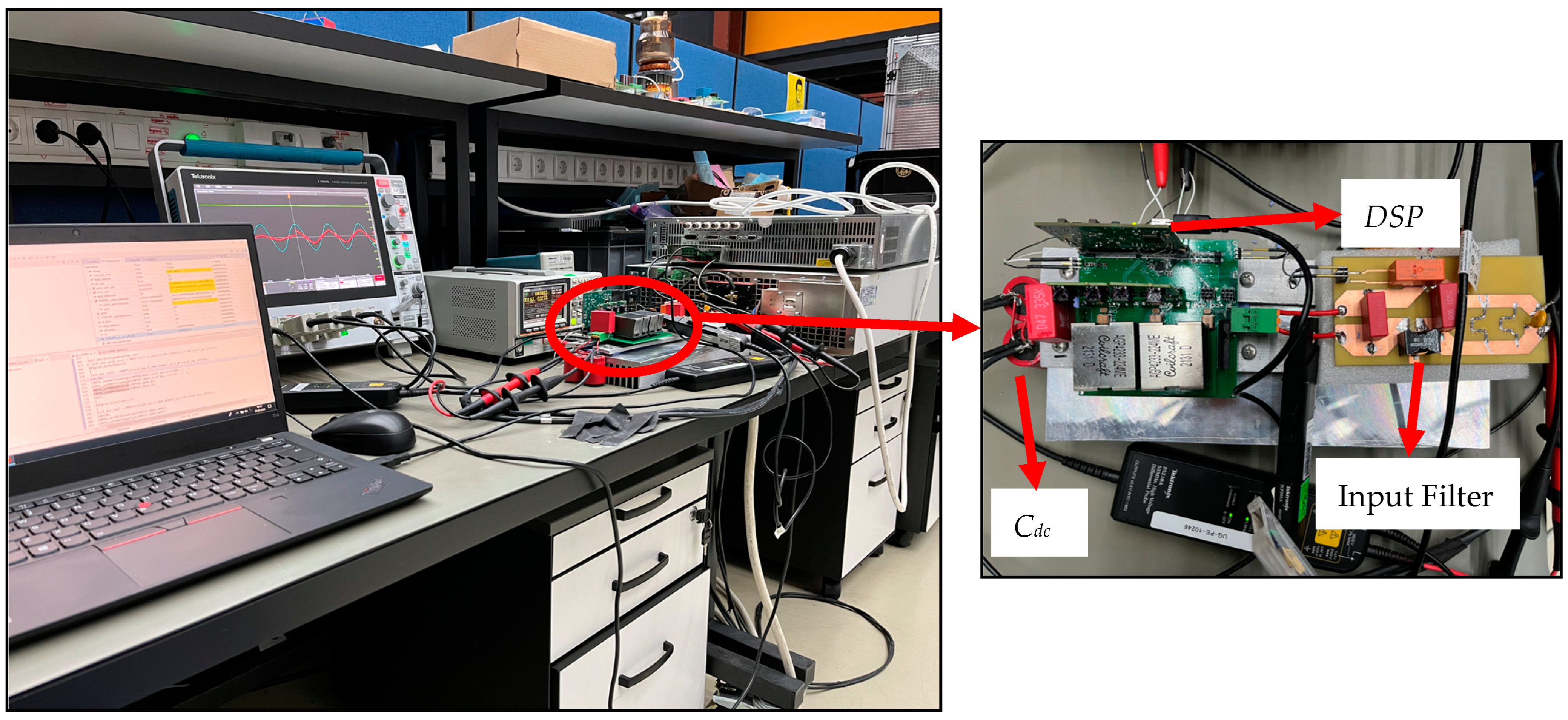
To verify the effectiveness of the proposed PCMC, it is applied to a prototype of the ITPPFC circuit. The experimental setup and circuit are shown in Figure 7. The parameters of the ITPPFC circuit are given in Table 1. The proposed digital PCMC technique is implemented with a 100 MHz DSP TMS320F280049C. The DSP includes internal comparators and DAC; thus, external analog components are not required.
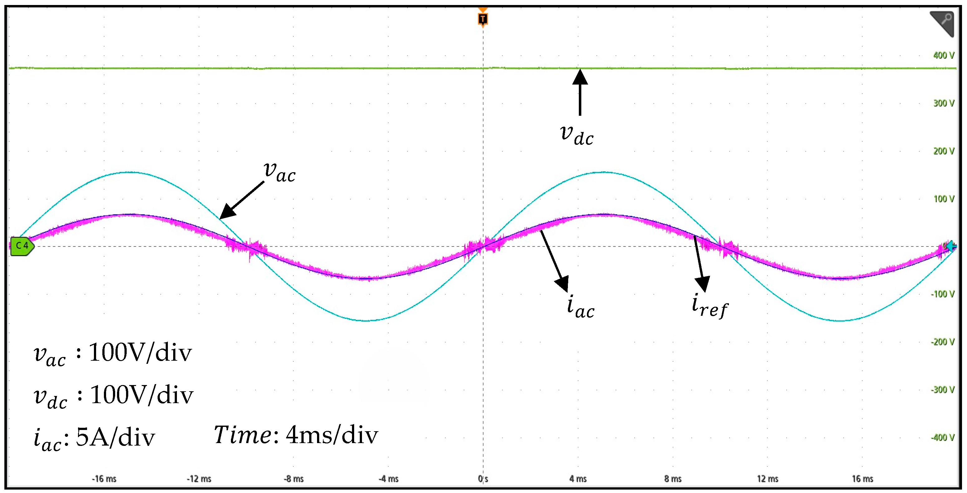
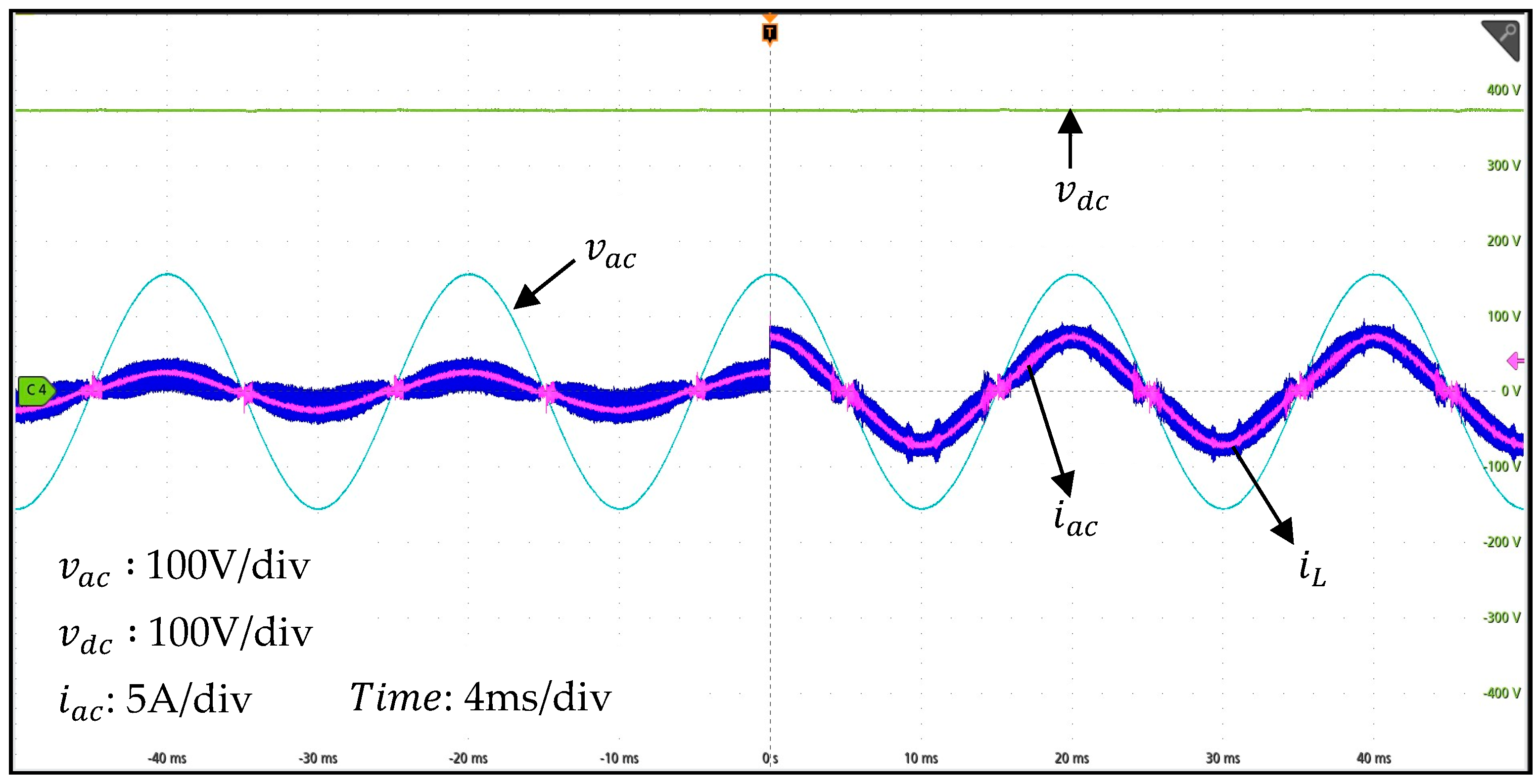
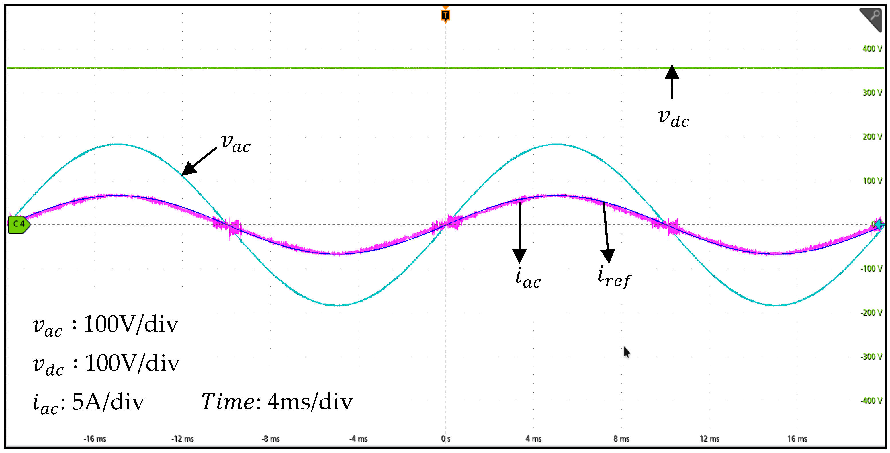
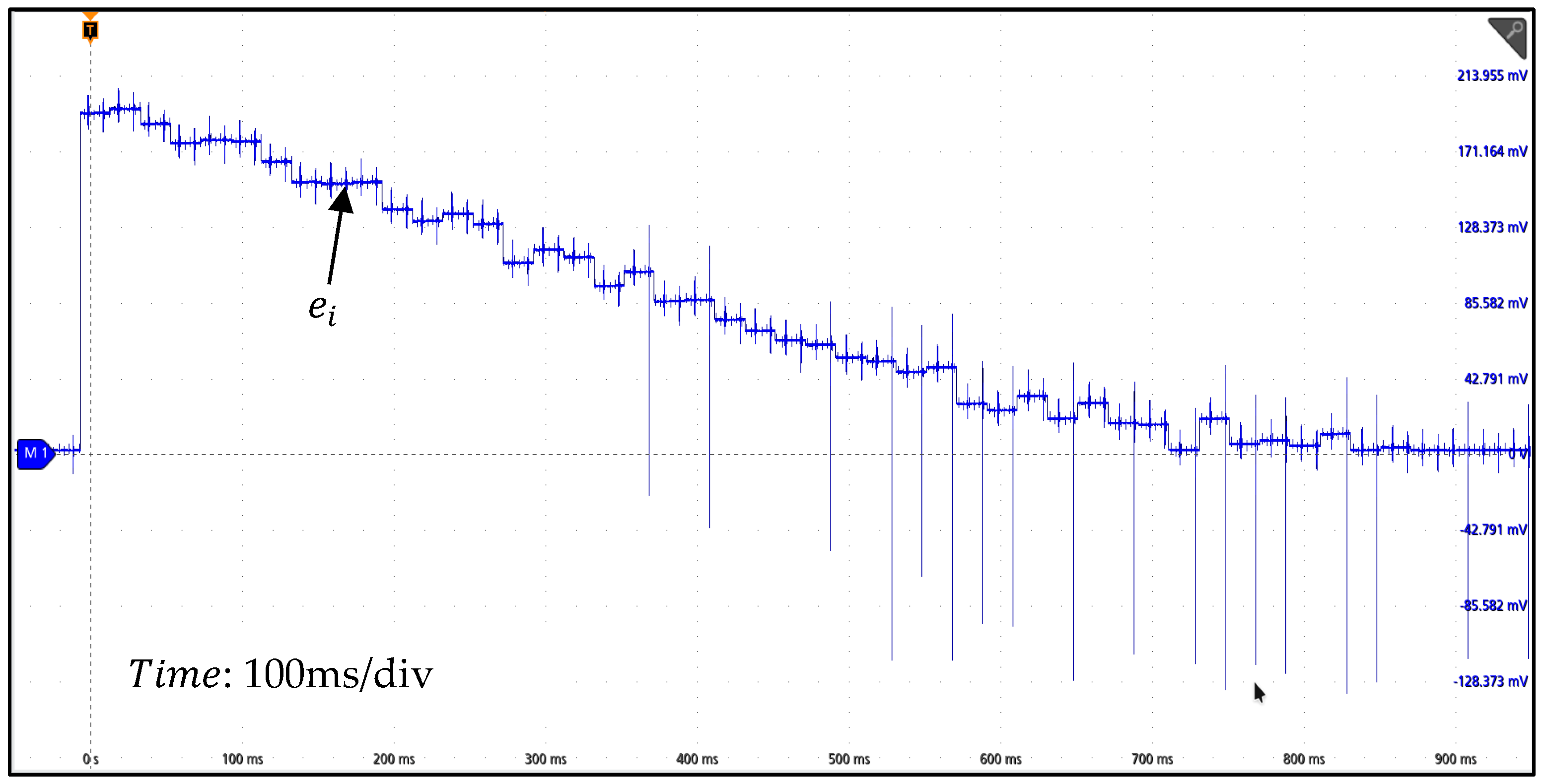
Figure 8 shows the accuracy of the reference current tracking for the nominal output power. The proposed current controller provides a good reference tracking. The input current THD is shown in Figure 9. The proposed current control method maintains low THD and high PF over a wide output power range. In Figure 10, the harmonic content of the input current is shown by comparing with the IEC 61000-3-2 Class D standards. Figure 11 shows the reference current tracking capability of the input current in response to the instantaneous variation of the current reference. The output power is changed from 30% to 100% and it is seen that the proposed current controller has a fast dynamic response. The stable operation is successfully achieved. The value of the inductance is critical for the PCC. The ideal PCC is sensitive against the variation of the inductance value. Figure 12 shows the effect of the inductance discrepancy. The inductance value used in the equations is selected as 0.75 times of the nominal inductance value. It is seen that the proposed current controller achieves a good reference tracking although the inductance value is not accurate. Figure 13 shows the error between the reference current and average current. The error waveform is obtained through a DAC with 1 mA/mV scale. It is seen that the error converges to zero with the increasing number of iterations of ILC.
On the other hand, the proposed method decreases the current spikes in the zero crossing regions of the totem pole PFC circuits. Since the PCMC is used in the current control, the inductor current is controlled without any delay on the contrary of the conventional PI controller. In conventional methods, a specific precaution is necessary such as soft start or applying different PWM modulation techniques in the zero crossing regions to solve this problem. However, the proposed method achieves this without additional process.
Table 2 compares the current control methods in the literature. Some methods do not consider the non-idealities for a simple design. However, this leads to the tracking error. Methods that include the non-ideal effects in the control increase the complexity of the model. Although the predictive current control method using the PI controller [19] wants to reduce the complexity, a controller design is required, and the dynamic response is adversely affected. Also, the predictive peak current mode control [33] is performed to improve the current control against the parameter variations. However, the complexity increases because many non-idealities are included in the control system. As a result, there is a tradeoff between the simplicity of the control system and the control performance. The proposed current control method stands out with its simplicity and control performance despite the non-ideal effects. The proposed method has a very good dynamic response. It is not required for the controller design. It performs a successful reference tracking. The method also differs from other predictive methods in that it does not perform square rooting in the average current prediction in DCM operation. The proposed method has a relatively low computational burden since square rooting is time consuming for the processor.

5. Conclusions

In this paper, a new digital PCMC method with ILC for ITPPFC circuit is proposed. The proposed method provides excellent current reference tracking despite the non-idealities and variations. The accuracy of the current reference is checked by comparing with the predicted input average current. Any difference between the predicted input average current and the reference current is minimized by iteration. The proposed ILC method successfully compensates the peak value of the controlled current. The proposed new current control method is implemented for the ITPPFC circuit under different load conditions. It is experimentally verified that it complies with IEC 61000-3-2 standard. The THD value of input current is low, and unity PF is obtained. The digital computational burden of the proposed method is quite low. This makes it suitable for converters operating at high-switching frequencies.

Author Contributions

Conceptualization, A.T.D. and A.F.B.; methodology, A.T.D. and A.F.B.; software, A.T.D.; validation, A.T.D.; investigation, A.T.D.; resources, A.T.D.; data curation, A.T.D. and A.F.B.; writing—original draft preparation, A.T.D.; writing—review and editing, A.T.D. and A.F.B.; visualization, A.T.D.; supervision, A.F.B. All authors have read and agreed to the published version of the manuscript.

Funding

This research was supported by the ASELSAN Inc.

Data Availability Statement

Data are included in the article.

Acknowledgments

The authors would like to thank ASELSAN Inc. for their support.

Conflicts of Interest

The authors declare no conflicts of interest.

References

  1. IEC 61000-3-2; Limits for Harmonic Current Emissions (Equipment Input Current <16 A per Phase). International Standard Organization: Geneva, Switzerland, 2001. Available online: https://webstore.iec.ch/en/publication/18726 (accessed on 5 October 2024).
  2. 80 PLUS Program. Available online: http://www.80plus.org/ (accessed on 20 December 2023).
  3. Environmental Protection Agency (EPA) Energy Star Program, Version 5.0 Computer Specifications. Available online: http://www.energystar.gov/ (accessed on 8 February 2023).
  4. Van de Sype, D.M.; De Gusseme, K.; Van den Bossche, A.P.; Melkebeek, J.A.A. A sampling algorithm for digitally controlled boost PFC converters. IEEE Trans. Power Electron. 2004, 19, 649–657. [Google Scholar] [CrossRef]
  5. Van de Sype, D.M.; De Gusseme, K.; Van den Bossche, A.P.; Melkebeek, J.A.A. Duty-Ratio Feedforward for Digitally Controlled Boost PFC Converters. IEEE Trans. Ind. Electron. 2005, 52, 108–115. [Google Scholar] [CrossRef]
  6. Ye, Z.Z.; Jovanovic, M.M. Implementation and Performance Evaluation of DSP-Based Control for Constant-Frequency Discontinuous-Conduction-Mode Boost PFC Front End. IEEE Trans. Ind. Electron. 2005, 52, 98–107. [Google Scholar] [CrossRef]
  7. Shin, J.W.; Cho, B.H. Digitally Implemented Average Current-Mode Control in Discontinuous Conduction Mode PFC Rectifier. IEEE Trans. Power Electron. 2012, 27, 3363–3373. [Google Scholar] [CrossRef]
  8. Hwu, K.I.; Chen, H.W.; Yau, Y.T. Fully Digitalized Implementation of PFC Rectifier in CCM Without ADC. IEEE Trans. Power Electron. 2012, 27, 4021–4029. [Google Scholar] [CrossRef]
  9. Zhang, W.; Feng, G.; Lui, Y.F.; Wu, B. A Digital Power Factor Correction Control Strategy Optimized for DSP. IEEE Trans. Power Electron. 2004, 19, 1474–1485. [Google Scholar] [CrossRef]
  10. Zhang, W.; Feng, G.; Lui, Y.F.; Wu, B. A New Duty Cycle Control Strategy for Power Factor Correction and FPGA Implementation. IEEE Trans. Power Electron. 2006, 21, 1745–1753. [Google Scholar] [CrossRef]
  11. Gusseme, K.; Van de Sype, D.M.; Van den Bossche, A.P.M.; Melkebeek, J.A. Digitally Controlled Boost Power-Factor-Correction Converters Operating in Both Continuous and Discontinuous Conduction Mode. IEEE Trans. Ind. Electron. 2005, 52, 88–97. [Google Scholar] [CrossRef]
  12. Chen, J.; Prodic, A.; Erickson, R.W.; Maksimovic, D. Predictive Digital Current Programmed Control. IEEE Trans. Power Electron. 2003, 18, 411–419. [Google Scholar] [CrossRef]
  13. Gusseme, K.; Van de Sype, D.M.; Van den Bossche, A.P.M.; Melkebeek, J.A. Input-Current Distortion of CCM Boost PFC Converters Operated in DCM. IEEE Trans. Ind. Electron. 2007, 54, 858–865. [Google Scholar] [CrossRef]
  14. Chen, M.; Mathew, A.; Sun, J. Nonlinear Current Control of Single-Phase PFC Converters. IEEE Trans. Power Electron. 2007, 22, 2187–2194. [Google Scholar] [CrossRef]
  15. Yao, K.; Ruan, X.; Mao, X.; Ye, Z. Variable-Duty-Cycle to Achive High Input Power Factor for DCM Boost PFC Converter. IEEE Trans. Ind. Electron. 2011, 58, 1856–1865. [Google Scholar] [CrossRef]
  16. Lim, S.F.; Khambadkone, A.M. A Simple Digital DCM Control Scheme for Boost PFC Operating in Both CCM and DCM. IEEE Trans. Ind. Appl. 2011, 47, 1802–1812. [Google Scholar] [CrossRef]
  17. Clark, C.W.; Musavi, F.; Eberle, W. Digital DCM Detection and Mixed Conduction Mode Control for Boost PFC Converters. IEEE Trans. Power Electron. 2014, 29, 347–355. [Google Scholar] [CrossRef]
  18. Park, J.; Kim, D.J.; Lee, K. Predictive Control Algorithm Including Conduction-Mode Detection for PFC Converter. IEEE Trans. Ind. Electron. 2016, 63, 5900–5911. [Google Scholar] [CrossRef]
  19. Chen, F.; Maksimovic, D. Digital Control for Improved Efficiency and Reduced Harmonic Distortion Over Wide Load Range in Boost PFC Rectifiers. IEEE Trans. Power Electron. 2010, 25, 2683–2692. [Google Scholar] [CrossRef]
  20. Luo, H.; Xu, J.; Luo, Y.; Sha, J. A Digital Pulse Train Controlled High Power Factor DCM Boost PFC Converter Over a Universal Input Voltage Range. IEEE Trans. Ind. Electron. 2019, 66, 2814–2824. [Google Scholar] [CrossRef]
  21. Choi, Y.; Kim, T.; Kim, R. An Active Partial Switching Method in Tertiary Loop for a High-Efficiency Predictive Current-Mode Control PFC Converter. IEEE Trans. Ind. Electron. 2018, 65, 7818–7828. [Google Scholar] [CrossRef]
  22. Luo, H.; Xu, J.; He, D.; Sha, J. Pulse Train Control Strategy for CCM Boost PFC Converter with Improved Dynamic Response and Unity Power Factor. IEEE Trans. Ind. Electron. 2020, 6, 10377–10387. [Google Scholar] [CrossRef]
  23. Moon, S.; Corradini, L.; Maksimovic, D. Autotuning of digitally Controlled Boost Power Factor Correction Rectifiers. IEEE Trans. Power Electron. 2011, 26, 3006–3018. [Google Scholar] [CrossRef]
  24. Li, S.; Lu, W.; Yan, S.; Zhao, Z. Improving Dynamic Performance of Boost PFC Converter Using Current-Harmonic Feedforward Compensation in Synchronous Reference Frame. IEEE Trans. Ind. Electron. 2020, 67, 4857–4866. [Google Scholar] [CrossRef]
  25. Nair, H.S.; Lakshminarasamma, N. An Improved Digital Algorithm for Boost PFC Converter Operating in Mixed Conduction Mode. IEEE J. Emerg. Sel. Top. Power Electron. 2020, 8, 4235–4245. [Google Scholar] [CrossRef]
  26. Li, L.; Zhang, Q.; Min, R.; Liu, K.; Tong, Q.; Lyu, D. A Current Reshaping Strategy to reduce Parasitics-Induced Current Distortion in Discontinuous Conduction Mode Boost Power Factor Correction Converter. IEEE Trans. Ind. Electron. 2021, 68, 2215–2224. [Google Scholar] [CrossRef]
  27. Bi, Y.; Zhao, T.; Li, H.; Xu, J.; Shu, G.; Wang, Y. Modified Deadbeat PRedictive Current Control Method for Single-Phase AC-DC PFC Converter in EV Charging System. IEEE Trans. Ind. Electron. 2023, 70, 286–297. [Google Scholar] [CrossRef]
  28. Lu, W.; Li, S.; Chen, W. Current-Ripple Compensation Control Technique for Switching Power Converters. IEEE Trans. Ind. Electron. 2018, 65, 4197–4206. [Google Scholar] [CrossRef]
  29. Wang, W.; Tzou, Y. Using Repetitive Control for Light Load THD and Efficiency Improvement for Boost Digital PFC Converters. In Proceedings of the 7th International Power Electronics and Motion Control Conference, Harbin, China, 2–5 June 2012. [Google Scholar]
  30. Cho, Y.; Lai, J. Digital Plug-In Repetitive Controller for Single-Phase Bridgeless PFC Converters. IEEE Trans. Power Electron. 2013, 28, 165–175. [Google Scholar]
  31. Ali, M.S.; Wang, L.; Alquhayz, H.; Ur Rehman, O.; Chen, G. Performance Improvement of Three-Phase Boost Power Factor Correction Rectifier Through Combined Parameters Optimization of Proportional-Integral and Repetitive Controller. IEEE Access 2021, 9, 58893–58909. [Google Scholar] [CrossRef]
  32. Nair, H.; Lakshminarasamma, N. A Computationally Simple Predictive CCM Average Current Controller with Nearly Zero Tracking Error for Boost PFC Converter. IEEE Trans. Ind. Appl. 2020, 56, 5083–5094. [Google Scholar] [CrossRef]
  33. Youn, H.; Park, J.; Park, K.; Baek, J.; Moon, G. A Digital Predictive Peak Current Control for Power Factor Correction with Low-Input Current Distortion. IEEE Trans. Power. Electron. 2016, 31, 900–912. [Google Scholar] [CrossRef]
  34. Fernandes, R.; Trescases, O. A Multimode 1-MHz PFC Front End with Digital Peak Current Modulation. IEEE Trans. Power. Electron. 2016, 31, 5694–5708. [Google Scholar] [CrossRef]
  35. Chandwani, A.; Dey, S.; Mallik, A. Parameter-Variation-Tolerant Robust Current Sensorless Control of a Single-Phase Boost PFC. IEEE J. Emerg. Sel. Top. Power Electron. 2022, 3, 933–945. [Google Scholar] [CrossRef]
  36. Zhang, J.; Zhang, Y.; Zaman, S.; Cao, R.; Gao, X.; Cao, M. Precise Correction of Current Zero-Crossing Distortion of Totem Pole PFC Converter. In Proceedings of the 2020 IEEE 9th International Power Electronics and Motion Control Conference, Nanjing, China, 29 November–2 December 2020. [Google Scholar]
  37. Roman, R.C.; Precup, R.E.; Hedrea, E.L.; Preitl, S.; Zamfirache, I.A.; Bojan-Dragos, C.A.; Petriu, E.M. Iterative Feedback Tuning Algorithm for Tower Crane Systems. In Proceedings of the 8th International Conference on Information Technology and Quantitative Management, Chengdu, China, 9–11 July 2021. [Google Scholar]
  38. Radac, M.B.; Precup, R.E. Data-driven model-free slip control of anti-lock braking systems using reinforcement Q-learning. Neurocomputing 2018, 275, 317–329. [Google Scholar] [CrossRef]
  39. Zamfirache, I.A.; Precup, R.E.; Petriu, E.M. Q-Learning, Policy Iteration and Actor-Critic Reinforcement Learning Combined with Metaheuristic Algorithms in Servo System Control. Facta Univ. Ser. Mech. Eng. 2023, 21, 615–630. [Google Scholar] [CrossRef]
  40. Killingsworth, N.J.; Krstic, M. PID tuning using extremum seeking: Online, model-free performance optimization. IEEE Control Syst. Mag. 2006, 26, 70–79. [Google Scholar]
  41. Kim, J.H.; Park, J.H.; Lee, S.W.; Cheng, E.K.P. A two layered fuzzy logic controller for systems with deadzones. IEEE Trans. Ind. Electron. 1994, 41, 155–162. [Google Scholar]
  42. Lewis, F.L.; Liu, K.; Selmić, R.R.; Wang, L.X. Adaptive fuzzy logic compensation of actuator deadzones. J. Robot. Syst. 1997, 14, 501–512. [Google Scholar] [CrossRef]
  43. O’Donovan, J.G.; Roche, P.J.; Kavanagh, R.C.; Egan, M.G.; Murphy, J.M.G. Neural network based torque ripple minimisation in a switched reluctance motor. In Proceedings of the IECON’94: 20th International Conference on Industrial Electronics, Control, and Instrumentation, Bologna, Italy, 5–9 September 1994. [Google Scholar]
  44. Xu, J.X.; Panda, S.K.; Pan, Y.J.; Lee, T.H.; Lam, B.H. A modular control scheme for PMSM speed control with pulsating torque minimization. IEEE Trans. Ind. Electron. 2004, 51, 526–536. [Google Scholar] [CrossRef]
  45. Sahoo, S.K.; Panda, S.K.; Xu, J.X. Indirect torque control of switched reluctance motors using iterative learning control. IEEE Trans. Power Electron. 2005, 20, 200–208. [Google Scholar] [CrossRef]
  46. Deng, H.; Oruganti, R.; Srinivasan, D. Analysis and Design of Iterative Learning Control Strategies for UPS Inverters. IEEE Trans. Ind. Electron. 2007, 54, 1739–1751. [Google Scholar] [CrossRef]
  47. Xu, J.X.; Panda, S.K.; Lee, T.H. Real Time Iterative Learning Control, 1st ed.; Springer: London, UK, 2009; pp. 7–27. [Google Scholar]
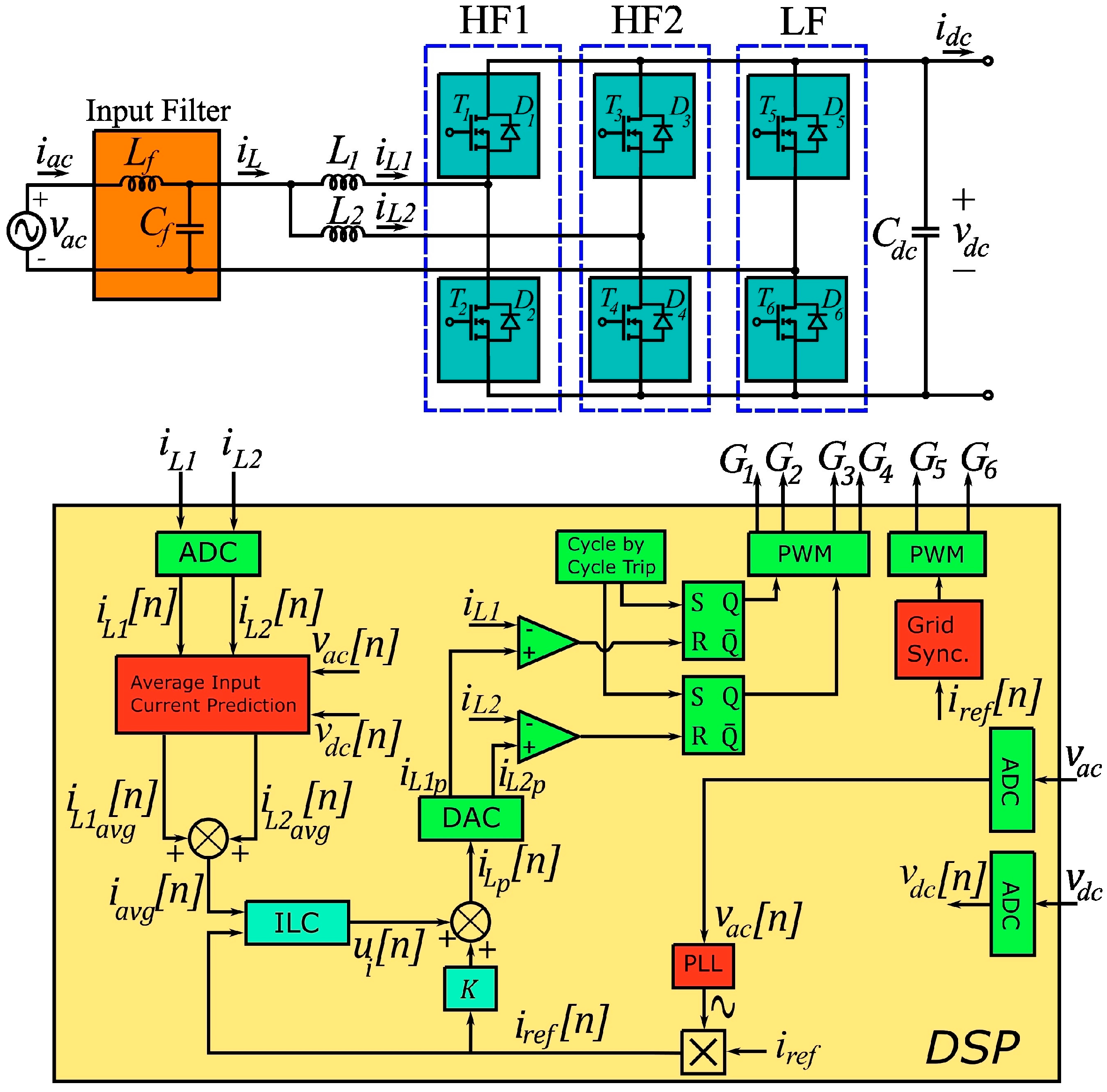
Figure 1. The proposed control scheme of the ITPPFC circuit.
Energies 17 05026 g001
Figure 2. The main block diagram of the proposed control algorithm.
Energies 17 05026 g002
Figure 3. The proposed ILC diagram.
Energies 17 05026 g003
Figure 4. Iteration domain and time domain for the proposed ILC method.
Energies 17 05026 g004
Figure 5. The convergence of the tracking error for (a) L = 0.001 , (b) L = 0.01 , (c) L = 1 .
Energies 17 05026 g005
Figure 6. The effect of the disturbances when the current controller is implemented using (a) the conventional PI current controller and (b) the proposed current controller.
Energies 17 05026 g006
Figure 7. The ITPPFC circuit hardware prototype.
Energies 17 05026 g007
Figure 8. Grid voltage, output voltage, reference current and grid current waveforms.
Energies 17 05026 g008
Figure 9. THD and PF curves at different input power levels.
Energies 17 05026 g009
Figure 10. Harmonic contents of the input current waveform with the proposed control method at full and half load.
Energies 17 05026 g010
Figure 11. The dynamic response of the proposed current controller when the output power is changed from 30% to 100%.
Energies 17 05026 g011
Figure 12. The experimental results in case of inductance discrepancy. The inductance value used in the equations is 0.75 times of the nominal inductance value.
Energies 17 05026 g012
Figure 13. Experimental result showing the error between the reference and average current in the proposed ILC-based current control method.
Energies 17 05026 g013
Table 1. Design parameters.
SymbolQuantityValue
vacInput Voltage110 Vac
vdcOutput Voltage380 Vdc
PoOutput Power250 W
L1, L2Boost Inductors220 µH
fLGrid Frequency50 Hz
fsSwitching Frequency100 kHz
CdcOutput Capacitor940 µF
LfFilter Inductor22 µH
CfFilter Capacitor1.5 µF
FForgetting Factor0.99
LLearning Gain0.01
Table 2. Comparison of the current controllers in literature and the proposed current controller.
Current
Controller
Affected by Changes in ParametersTracking ErrorRequirement of Controller DesignComplexityDynamic ResponseComputational Burden
PI controller [6]YesLargeYesSimpleLowLow
Ideal Predictive Controller [10,12,18]YesLargeNoSimpleMediumMedium
Predictive Current Controller
with PI Feedback
action [19]
MinimalSmallYesSimpleLowMedium
Predictive Average Mode Current Controller [32]MinimalVery SmallNoSimpleVery HighLow
Predictive Peak Current Mode Controller [33]MinimalSmallNoHardMediumHigh
Proposed Current ControllerNoVery SmallNoSimpleVery HighLow
Disclaimer/Publisher’s Note: The statements, opinions and data contained in all publications are solely those of the individual author(s) and contributor(s) and not of MDPI and/or the editor(s). MDPI and/or the editor(s) disclaim responsibility for any injury to people or property resulting from any ideas, methods, instructions or products referred to in the content.