Article

The Coordinated Power Control of Flexible DC Microgrids in Sustainably Optimized Yacht Marinas

by
Andrea Alessia Tavagnutti
,
Serena Bertagna
,
Marco Dalle Feste
,
Massimiliano Chiandone
,
Daniele Bosich
*,
Vittorio Bucci
and
Giorgio Sulligoi
Department of Engineering and Architecture, University of Trieste, 34127 Trieste, Italy
*
Author to whom correspondence should be addressed.
Energies 2024, 17(2), 521; https://doi.org/10.3390/en17020521
Submission received: 14 December 2023 / Revised: 11 January 2024 / Accepted: 19 January 2024 / Published: 21 January 2024
(This article belongs to the Special Issue Sustainable/Renewable Energy Systems Analysis and Optimization)

Abstract

:
Nowadays, the industrial world is undergoing a disruptive transformation towards more environmentally sustainable solutions. In the blue economy, this new approach is not only expressed in the domain of actual vessels, but also in the development of charging infrastructure, displaying a notable transition towards more eco-friendly solutions. The key focus lies in adopting flexible power systems capable of integrating renewable energy sources and storage technologies. Such systems play a crucial role in enabling a shift towards low-emission maritime transport. The emissions reduction goal extends beyond onboard shipboard distribution systems, encompassing also the design of supplying platforms and marinas. This study explores the implementation of a controlled DC microgrid tailored to efficient management of power flows within a yacht marina. Once having established the interfaces for the vessels at berth, the integration between the vessels, the onshore photovoltaic plant and the battery storage unit is made possible thanks to the coordinated management of multiple power converters. The overarching goal is to curtail reliance on external energy sources. Within this DC microgrid framework, a centralized controller assumes a pivotal role in orchestrating the power sources and loads. This coordinated management is essential to achieve sustainable operations, ultimately leading to the reduction of emissions from both ships and onshore power plants.

1. Introduction

Environmental considerations are emerging as critical factors in the global development of society. To actively contribute to a sustainable trajectory in this green transition, both the scientific and industrial communities are directing their efforts towards the creation of flexible and resilient solutions, while also maximizing the utilization of existing ones. Among the industrial sectors, transportation stands out as one of the most impactful, both in terms of energy consumption and the emission of greenhouse gases [1,2]. In recent years, there has been a notable surge in the advancement of electric transportation [3], observed in both land-based and maritime applications [4]. Regarding the maritime sector, the transition to greener electrification involves multiple dimensions, ranging from innovations in onboard power systems [5,6,7] to the implementation of the cold ironing concept [8,9]. Foreseeing a rise in the number of electric ships, the latest electrical infrastructure in marinas is being designed to accommodate this significant shift, spanning both recreational and commercial sectors. To ensure comprehensive environmental benefits, the utilization of sustainable energy from Renewable Energy Sources (RESs) is imperative. However, sources like photovoltaic (PV) plants pose a challenge, as they do not guarantee a constant and uninterrupted power supply, needing support from energy storage systems [10]. This approach allows storage of the surplus renewable energy during periods of excess production and its use when production falls short of demand. In the light of advancements in control and management technologies, DC microgrids [11,12,13] emerge as promising solutions, applicable in onboard distribution, ports, and marinas. These controlled power systems have the capability to integrate the utilization of RESs, energy storage, and hybrid–electric ships within a marina context [14]. In the pursuit of no-emission marinas [15,16], effective management of these three elements is essential to achieve specific goals, either optimizing power production and consumption or realizing economic benefits through the sale of excess RES power. Consequently, the coordination of control tasks becomes of paramount importance, leading to the development of strategies that prioritize both system efficiency and green sustainability [17]. This topic has been introduced in [16], but techno-economic evaluations were lacking. Therefore, the present paper starts from the application to an existing marina in [16], while giving an additional, and essential, economic perspective on the adoption of the proposed solution and control. To this aim, from some raw initial data (e.g., annual irradiation profile for Trieste area, PV power plant sizing and loads to be fed), the Homer optimizer is adopted to provide a techno-economic–environmental evaluation. The latter can identify the most feasible solution in supplying the yacht marina by renewable energy. Storage support is also considered in Homer analysis, thus completing the assessment results. The power system under study incorporates photovoltaic (PV) modules, Battery Energy Storage Systems (BESSs) and multiple electrical connections catering to docked ships. The microgrid is designed for the refurbishment of the existing Port San Rocco marina, located near Trieste in northeastern Italy. To enhance the realism of the proposal, the feasibility of integrating PV sources is evaluated using Homer Pro software. This tool not only conducts a techno-economic analysis to assess environmental benefits, such as emission reductions, but also evaluates the return on investment. Within the designed DC microgrid, a connection to the main AC grid is established. This connection ensures a stable power supply in scenarios where green energy sources are unavailable, such as during nighttime. Simultaneously, it facilitates the selling of excess energy when the marina’s power production surpasses local demand. The adaptability and resilience of the DC microgrid’s operation are overseen by a Power Management System (PMS), responsible for coordinating power flows through power electronics converters. To validate the proposed design, real-time emulations on the Typhoon HIL platform are employed. This platform allows for testing the control mechanisms on the interface converters. The results of a day-to-night transition are presented and discussed, demonstrating the marina’s ability to efficiently manage the charging of docked vessels, even during periods without sunlight.

2. The Green Yacht Marina

The increasing attention to reducing the environmental footprint of various economic sectors has also hit the maritime industry, with a growing demand for intensifying efforts towards the implementation of sustainable supply, production and logistics chains. In this context, important players are represented by port and marina structures due to their features and, particularly, their position. Indeed, they are often located in surrounding areas near cities and natural environments and involve the traffic of numerous vessels. As a result, favorable public opinion and acceptance is not an easy target to achieve [18], even more for marinas that might be seen as unnecessary producers of atmospheric pollution (i.e., in an economy related to tourism/recreational purposes). To enhance their environmental commitment, marinas around the world are implementing approaches and strategies aimed at supporting sustainable planning and energy management [19,20]. Some of these measures are explained in detail below and can find application in other touristic sites, such as the Italian Yacht Marina in Porto San Rocco (Figure 1), located in Trieste, Italia.

2.1. Sustainability in Yacht Marinas

Marinas play a pivotal role in regions where the blue economy is a significant economic driver. They are crucial for fostering tourism and recreational activities, leading to a substantial increase in their number in recent years [21]. Given the set of services marinas are expected to provide to customers and boat owners, they have become noteworthy consumers of energy. Moreover, the propulsion and generation systems of pleasure craft have undergone a profound transformation, with electrification becoming a predominant trend in marine applications [22,23]. This shift towards electrification has consequently increased the energy requirements of marinas, necessitating the exploration and integration of new energy sources. The environmental aspect is also integral to this analysis, as green energy production stands as a cornerstone and a significant challenge to Industry 4.0 [24]. Sustainability has emerged as a critical economic driver, influencing customer attention and choices. In the context of marinas, the ultimate objective is to implement technologies for low-impact energy production by renewable sources [25]. Smart marinas, capable not only of acting as consumers but also as providers of energy, stand to gain economic benefits by reducing berthing costs and offering additional services.
This approach positions a system, comprising marinas as energy hubs and electric vessels, within the framework of the green logistics trend [26]. This not only contributes to environmental sustainability but also enhances the overall image. From an economic standpoint, the potential market is relevant, with the global nautical fleet boasting over 33 million pleasure crafts, yet only 13% are currently moored in equipped marinas [27]. For all these reasons, it is necessary that new generation marinas will evolve into Zero Emission Marinas (ZEMars), a concept consequent to Zero Emission Mode navigation. In comparison with standard berthing infrastructures, the ZEMar is thus designed to ensure advanced services. Firstly, the fast recharge of onboard energy storage systems is enabled. Secondly, the ZEMar can be managed in a sustainably optimized way by exploiting the local RES (like photovoltaic or wind power plants) in feeding the Shore Connection platforms. Finally, the ZEMar can also guarantee additional ancillary services (e.g., local buffer energy storage for the DSO grid).

2.2. Hosted Vessels

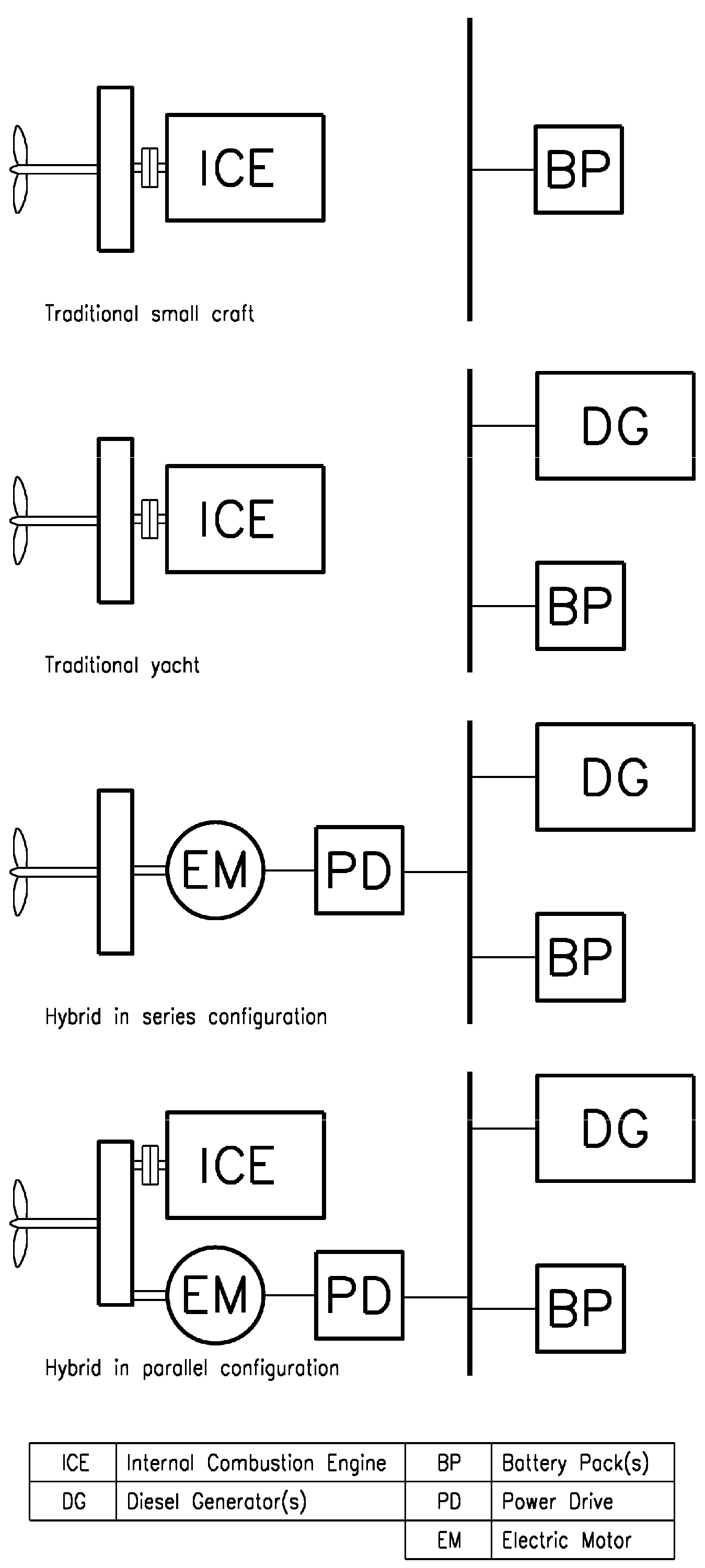
The electrification trend in transportation has extended to the motorboat sector, offering notable advantages. Electric navigation provides a silent, clean, comfortable, and relaxing experience with no vibrations and zero harmful emissions. The global market for electric-powered boats reached $4.5 billion in 2020, demonstrating a fast-growing industry with an estimated compound annual growth rate (CAGR 2021–2026) of approximately +12.65%. The COVID-19 pandemic initially hindered the electric boat and ship market due to manufacturing facility closures and global trade restrictions [28]. However, as governments ease restrictions to boost economic conditions, the market is expected to rebound in the near future. With over 100 manufacturers in the electric boat and pleasure ship sector, the market for hybrid and pure electric boats and ships is projected to exceed $20 billion globally by 2027 for non-military versions. Recreational boats lead in sales numbers, followed by underwater leisure and autonomous underwater vehicles. Despite a long history, electric and hybrid watercraft occupy a relatively modest market share of around 1–2% of the addressable market. All-electric propulsion systems involve an electric motor powered by a battery pack, while hybrid–electric systems combine a fueled engine with energy storage for either direct propulsion or battery charging. The choice between these configurations is determined by the onboard storage system capacity, which varies with the size of the boat or ship. In particular, Table 1 shows the average capacity of the battery packs according to the overall length of traditional pleasure craft, while Table 2 shows the values for hybrid–electric propulsion boats. In the realm of smart marinas, future developments should not only prioritize maintaining the battery packs of traditional boats but also focus on providing enough energy for charging hybrid–electric propulsion vessels. This category is indeed experiencing notable growth, particularly in the “up to 10 m” and “over 60 m” segments. Figure 2 shows the reference diagrams for the propulsion and electrical generation systems of the various types of yacht considered. The former can be found on small boats, while the latter represents the state of the art for most pleasure boats, even large ones. The last two diagrams show integrated hybrid–electric propulsion systems in series and parallel configuration, respectively.

3. DC Microgrid in Yacht Marinas

In the context of renewable marinas, this section presents an advanced electrical distribution system to maximize the power exploitation from a PV field. In order to increase the marina’s sustainability, a converter-dense [29] DC microgrid is envisaged to optimize the power flows in the controlled grid. The wide employment of power converters can increase the flexibility in microgrid operation, thus allowing the storage of green energy in moored crafts. Marina management can also open interesting scenarios when selling the PV energy to the main distribution system.

3.1. Controlled Power System

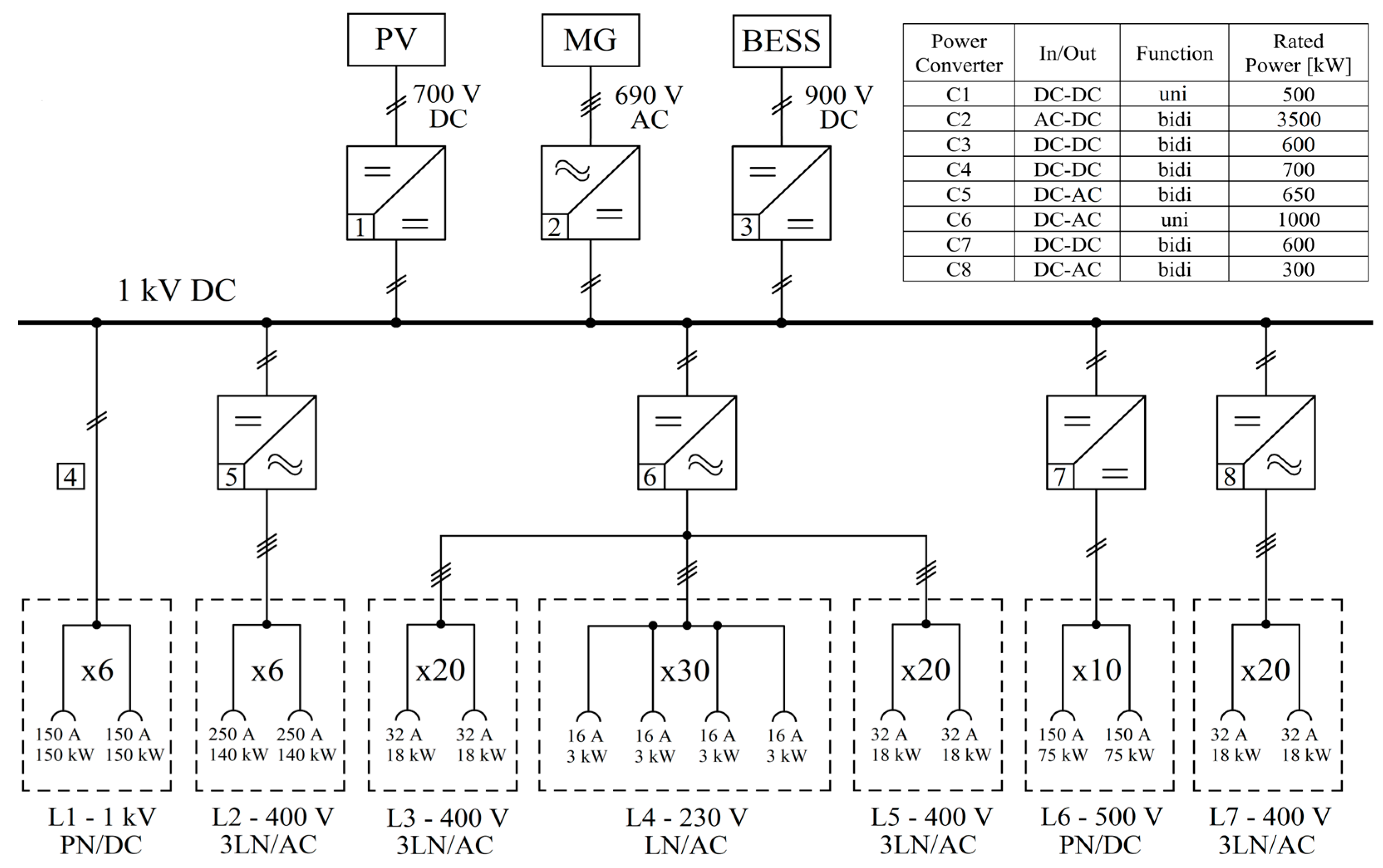
The DC microgrid in Figure 3 is designed to ensure efficient power management in the marina. A smart strategy is to be conceived for both promoting the exploitation of the PV source and the bidirectional power flow from/to the berthed vessels. These two outcomes are well-received when fostering a marina with low environmental impact and the sale of no-emissions energy to the DSO grid. Also important is the role of the embarked energy storage, which is integrated onboard for the ship’s functioning and to enable a rewarded power exchange with the external grid. On the other hand, charging from the grid can follow a minimum price law to limit the economic burden for ship owners. In the 1 kV-DC grid under consideration, eight power converters are installed to ensure power balancing among sources, loads and storage. The converters’ data are defined in the table of Figure 3. Three converters (i.e., C1, C2 and C3) are in the upper part of the power scheme. The C1 is a unidirectional DC–DC boost converter to interface the PV field to the DC bus. Conversely, the C2 is a bidirectional AFE rectifier to alternatively supply the harbored vessels from outside, or to address the marina power surplus to the 10/0.69 kV-main grid. The marina grid is also provided with a Battery Energy Storage System (BESS) to provide voltage regulation and power buffering functionalities. This BESS is interfaced to the distribution with its DC–DC converter, named C3. This is responsible for managing the charge and discharge phases of the 500-kWh battery.
The lower part of Figure 3 introduces five converters, each sized based on the total power of the jetties’ electrical sockets (dashed boxes) and a utilization-contemporaneity factor of approximately 0.4. C4, situated on the moored vessel, is a bidirectional DC–DC converter connecting mega-yachts with 1 kV-DC onboard distribution. C5 is another bidirectional module, with AC serving as the interface to the shipboard grid. In contrast, C6 is a unidirectional DC–AC converter designed for charging both 3-phase and single-phase sockets. Due to the complexity of managing a bidirectional power flow, a unidirectional interface (from grid to ship) is preferred for now. Lastly, C7 and C8 work to transmit power in both directions. C7 is designed for DC ships, while C8, an AFE inverter, handles bidirectional power exchange with AC vessels. All power grid data are comprehensively presented in Figure 3. The “x” multiplied by a number is used to replicate the same jetty for a specific number of times in the marina installation. Concerning bidirectional converters, the capacity associated with each socket on the 1 kV DC mega-yacht corresponds to 0.5–1 MWh of battery. This capacity is consistent for each socket supplied by C5. C7 features a smaller capacity, with 0.25–0.5 MWh per socket for DC ships. The capacity is further reduced to 40 kWh for each socket supplied by the C8 converter.

3.2. PV Plant Design

In this sub-section, a photovoltaic power plant is designed to sustainably feed the yacht marina. By covering the parking area (80 m × 30 m is the surface), 2400 m2 are made available for the PV modules. Then, an additional area on the buildings (40 m × 40 m) gives another 1600 m2 to be exploited for the photovoltaic installation. By assuming a quite standard efficiency for the PV technology (i.e., 125 W/m2 from the 1 kW/m2 incoming radiation), the available surface of 4000 m2 can provide 500 kW for charging both vessels charging and for energy selling to the DSO.

3.3. Optimization Assumptions

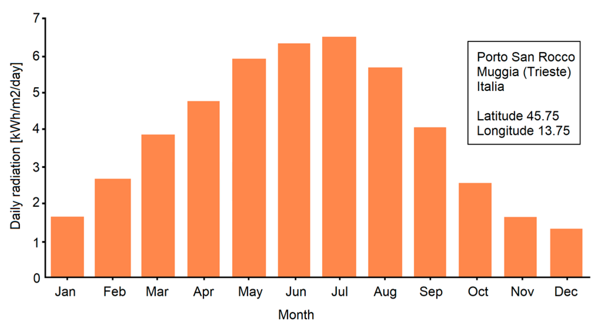
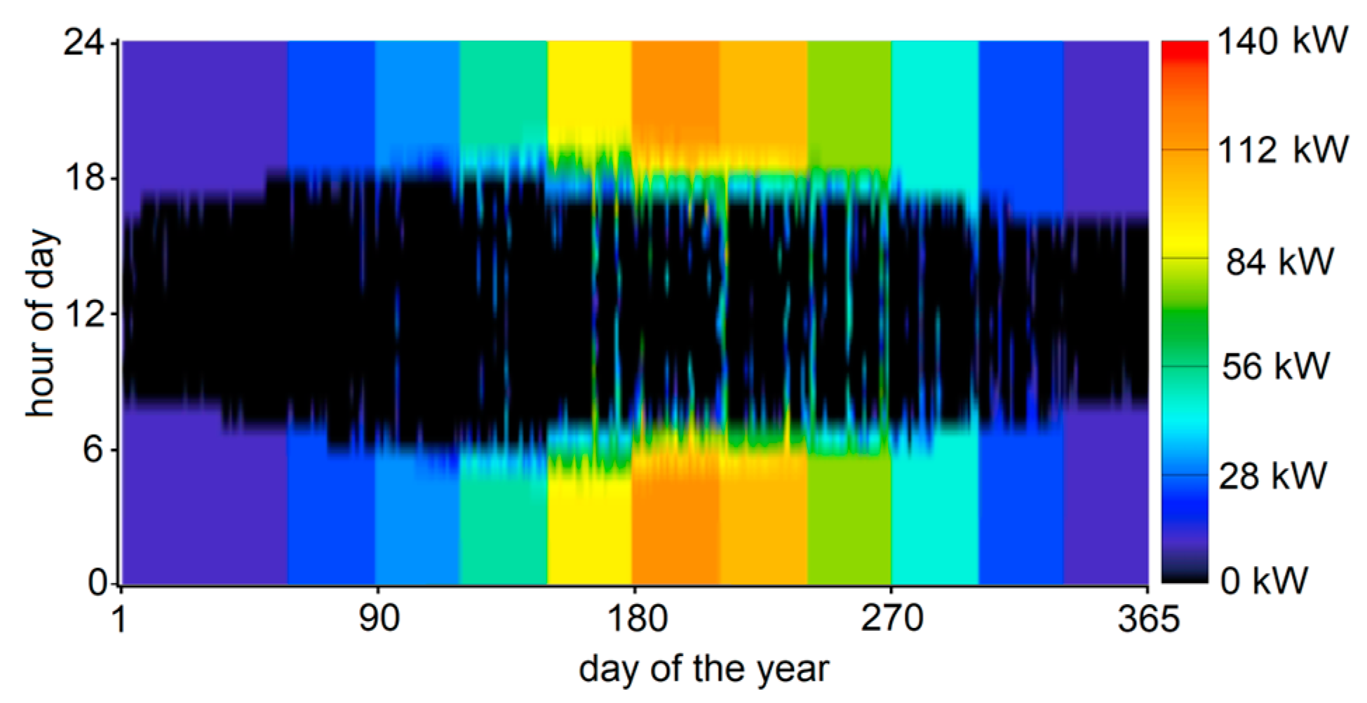
In the DC microgrid, three systems (PV, storage, interface converter) are combined to pursue the sustainability goal. The Homer software can identify the most feasible combination of these systems from a techno-economic point of view. The Return on Investment (ROI) is thus evaluated by considering the presence/absence of each element. Homer software starts its optimization from an initial simplified microgrid topology. The latter is shown in Figure 4, where a double AC–DC distribution is adopted to interface storage and PV power. Although the DC distribution in the marina is designed to charge the batteries, as in Figure 3, some assumptions are specified here to exploit the optimization engine. Firstly, the power demand from vessels is aggregated in an equivalent AC load, albeit in reality the onboard batteries receive energy from the DC bus (Figure 3). The AC grid in Figure 4 has an external input from AC distribution and a power converter to the DC section. The PV modules are modeled to provide 500 kW, while the storage system is sized as 500 kWh. In Figure 4, the DC distribution is interfaced to the AC by an equivalent AC/DC converter to be modeled in Homer. The economic analysis takes in both installation and replacement costs. To this aim, the unit price of PV modules is $900/kW, while that for the converter is $200/kW. Finally, Li-Ion storage costs $800/kWh. To quantify the convenience of PV-storage installation, average costs for purchase ($0.361/kWh) and sale ($0.040/kWh) of energy from/to the DSO are also to be considered. The optimization analysis is fulfilled for two load scenarios, as in Table 3. For each month, the load power to be fed is expressed as kW value or as percentage of the total power demand (i.e., 3250 kW on charging units). In the first HI scenario, the microgrid feeds the entire charging load on the vessels. Instead, the profile LO considers a reduced load amount. Other input data for the energy optimization are the yacht marina position as latitude–longitude (45.75–13.75). From this information, the daily radiation for each month can be estimated (Figure 5) on the NASA database to later define the average energy production from PV.

3.4. Techno-Economic–Environmental Evaluation

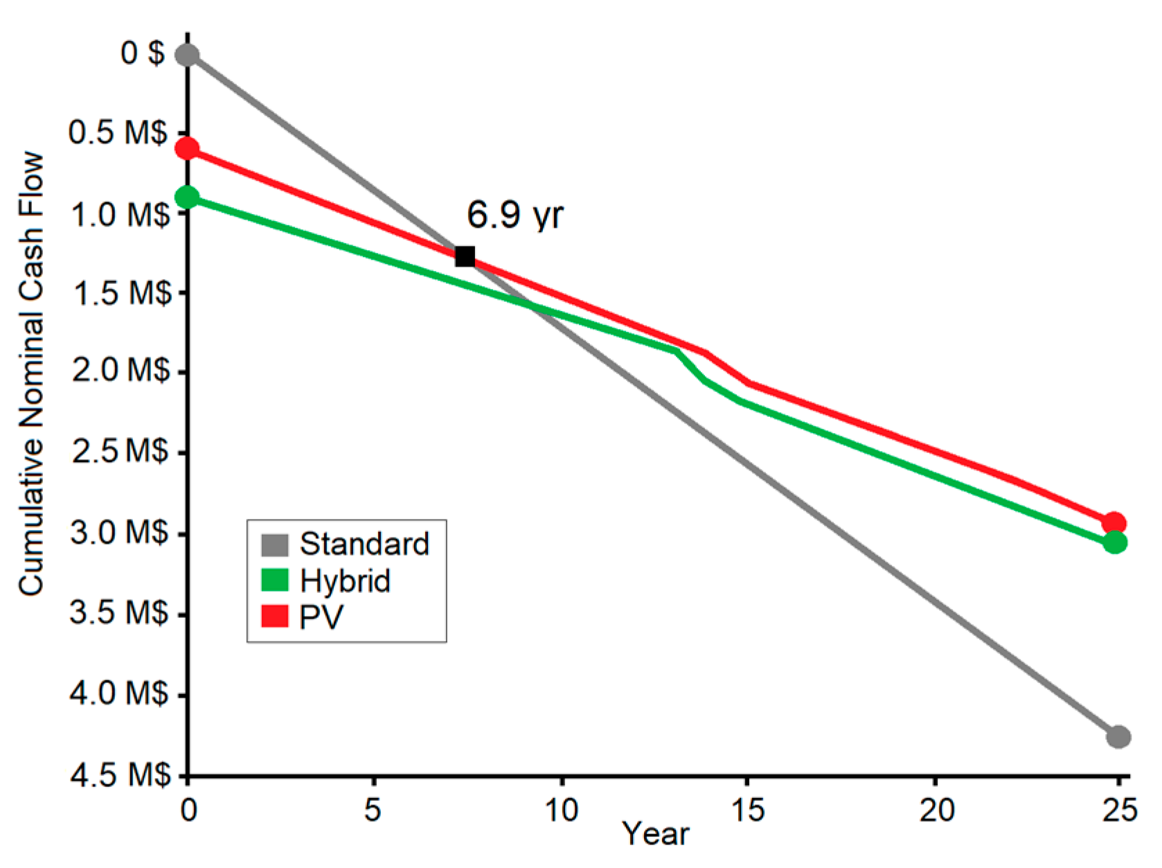
The Homer optimizer provides conclusions from economic and techno-environmental points of view. The first analysis compares three cash flows, as in Figure 6. The Standard is the scenario where the marina is entirely powered from DSO. Then, PV is the solution where only PV contributes to supplying the marina. Finally, Hybrid is the case where both PV and marina battery work to charge the shipboard storage. This solution is evidently more advanced, as the land Li-Ion storage can provide a buffering support. By hypothesizing a 25-year life for the system, the minimum LCOE optimizer elects the basic PV solution as winner, being smaller in its investment return (6.9 yrs.). In the optimized solution, on the one hand, the Homer engine disregards the storage as unfavorable (red line in Figure 6), and on the other imposes the converter’s rated power, equal to 500 kW. Conversely, as the Hybrid solution should also amortize the Li-Ion battery cost, its return time is larger (about 10 yrs.). Once the PV solution is chosen as winner, other analyses are developed to clarify the energy balance and the purchase–sale of energy in a reference-year. Although the study is performed for both load profiles, for simplicity only the results for the HI case are here reported. The same conclusions could also be transferred to the LO configuration. Particularly, Figure 7 depicts the monthly balance between the energy purchased from the grid and that produced by the PV system. It is remarkable how the PV installation can greatly contribute to marina powering (i.e., about 65% of total annual energy). Figure 8 depicts the power purchased from the grid for one year. Evidently, the larger purchase (about 135 kW) is in the night hours of the summer months, when the power request is higher from charged ships. Next, Figure 9 provides the power that is sold to the DSO. In this case, the best PV contribution is during lunchtime, when the sun is stronger. To complete the study, environmental results are also provided. From the emissions for the Standard case (293,656 kg/yr. CO2, 1273 kg/yr. di SOx, 623 kg/yr. NOx), the environmental benefits are undeniable when evaluating the performance for the PV case (167,295 kg/yr. CO2, 725 kg/yr. di SOx, 355 kg/yr. NOx). The tons of CO2 equivalent not emitted in the PV case (about 170 tons each year) are noteworthy in the context of system sustainability. Similar results are shown for the Hybrid case.

3.5. Final Considerations

Although the study shows how the PV solution is able to provide impressive techno-environmental results with shorter ROI, a final remark rehabilitates the Hybrid plant. Similar time to recover the investment (Δ = 3 yrs.), extended flexibility, redundancy, and back-up power are the most important reasons to install a storage system as in the next sections.

4. Coordinated Power Management

The flexible DC microgrid is smartly controlled to ensure a time-varying power management, thus increasing marina sustainability. The power exchanged with the main distribution grid is managed by considering the PV field power availability, as well as the operating needs of the berthed vessels. The simultaneous utilization of photovoltaic RES and battery storage serves to reduce reliance on energy procurement from the primary grid. Moreover, the combination of RES and energy storage opens up the possibility of selling emission-free energy, generated by the marina during periods of low demand for charging vessels. To explore the marina’s capabilities in supporting environmentally friendly initiatives, a particular scenario is envisioned. This scenario revolves around a night-to-day transition, during which the PV power plant is carefully regulated to initiate power supply to the managed electrical grid.

4.1. Advanced Control Strategy for Flexibility

The operation of the green marina in Figure 3 is managed by a centralized [30] Power Management System (PMS) that receives all the signals from the field components and coordinates the power flow to/from each converter. The PMS optimizes the power production and consumption inside the microgrid, guaranteeing both economic benefits to the ship owners and the proper exploitation of green energy. To this aim, the PMS sends the change in control signal and power references to the different converters. In this work, the focus is on how to manage the night–day transition by using the C2 grid converter and the C3 BESS converter. These operate to balance the available power, while maintaining steady bus voltage [31]. Both converters can be operated in power or DC bus voltage control mode. If the power control mode is selected, the central controller sends the power reference to the converter. Instead, if the bus voltage control is chosen, the PMS sends the voltage reference and the eventual droop signal. If both the converters are in voltage control mode, the power sharing is managed by changing the droop signal.
The droop control law is expressed in Equation (1), in which the main 1 kV DC bus voltage, VBUS, is reduced from the desired reference value, VBUS*, of a quota that is directly related to the converter current, thus I2 or I3, and its respective droop coefficient, Rd2 or Rd3. By managing the two droop coefficients, thus Rd2 for converter 2 and Rd3 for converter 3, it is possible to tune the power output of each converter, while stably regulating the DC bus voltage. Working on Equation (1), the relation between the droop coefficients and the converters current is expressed in Equation (2). By multiplying and dividing Equation (2) for the bus voltage, the ratio between the output powers of the two converters is derived, as in Equation (3). When the PMS modifies the droop coefficients, consequently the power output from the two converters in charge of bus voltage regulation is tuned. These droop values, indeed, can either be fixed, if the ratio between the output power of the two converters is envisioned to remain constant in all the operating conditions (e.g., equal droop coefficients), or they can be changed according to the need of the power system. For this purpose, the change can be done in a sharp way by modifying the droop coefficient with a step. However, a better way to carry out this functionality is by performing a smooth transition from the initial value to the final one, thus by using the so-called dynamic droop [32,33]. In the present work, it has been decided to modify the droop coefficients using a ramp. The droop control does not need any additional communication line, and it is favorable for stability since it adds a steady-state additional damping to the system with the direct introduction of virtual resistances.
Indeed, by observing the wide presence of high-bandwidth controlled converters and LC filers in the yacht marina’s DC microgrid, additional stabilizing signals could be added to compensate for the possible Constant Power Loads instability [6]. To conveniently ensure DC system stability, further stabilizing contribution during critical perturbations (e.g., load steps, generator disconnections) can be obtained when the droop effect is transiently modified by a transfer function [34]. During critical perturbations, this control approach can provide large droop resistances (i.e., high values on the Bode diagram’s high-frequency zone) to force the poles’ transition in the Gauss left-half complex plane, thus ensuring stable behavior, while reduced droop resistances (i.e., small values on the Bode diagram’s low-frequency zone) are tuned to properly subdivide the power contribution among paralleled converters in a steady-state condition. This is not performed in this work, the focus lying more on coordinated control than on voltage stability; however, the introduction of the active damping could be interesting for future work.
V B U S = V B U S * R d 2 I 2 = V B U S * R d 3 I 3
I 2 I 3 = R d 3 R d 2
P 2 P 3 = R d 3 R d 2
The BESS converter is always demanded by the bus voltage control. Indeed, the batteries work to absorb the voltage fluctuations in the DC feeder [35] and to assist the microgrid operations during transitions from one operating condition to another. As the bus voltage is always regulated, the other converters can operate in power control mode, and their power reference is increased with a ramp-rate of 100 kW/s. In the test described in the next Section, the night-to-day transition of the green marina is hypothesized. Before the sun starts to rise, the bus voltage is controlled in droop mode by the C2 and C3 converters, the PV converter is disconnected, and the ships’ converters are all power controlled. Some ships are supplying the bus and others, instead, are being charged. The amount of generating power that is lacking is fully supplied by the grid. This option is ensured by properly setting the droop gain ratio between C2 and C3. By foreseeing the oncoming sunrise, the droop ratio between the voltage-controlled converters is changed dynamically, to smoothly switch the power supply from the grid to the batteries. At this point, the sun is up and the PV converter is connected. Its power output exceeds the needs of the load, therefore this excess of power is automatically delivered to the batteries. When these storages are sufficiently charged, they are capable of regulating the bus voltage without the assistance of the external AC grid. In such a condition, the extra power can, indeed, be sold. To this purpose, the grid converter is switched to power control mode and the excess of power is sent to the main AC distribution grid.

4.2. Scenario under Test

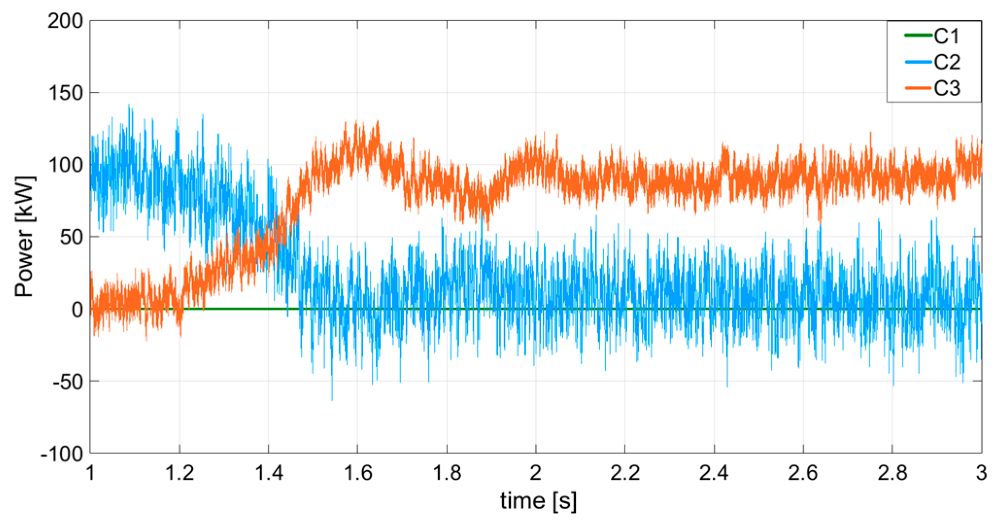
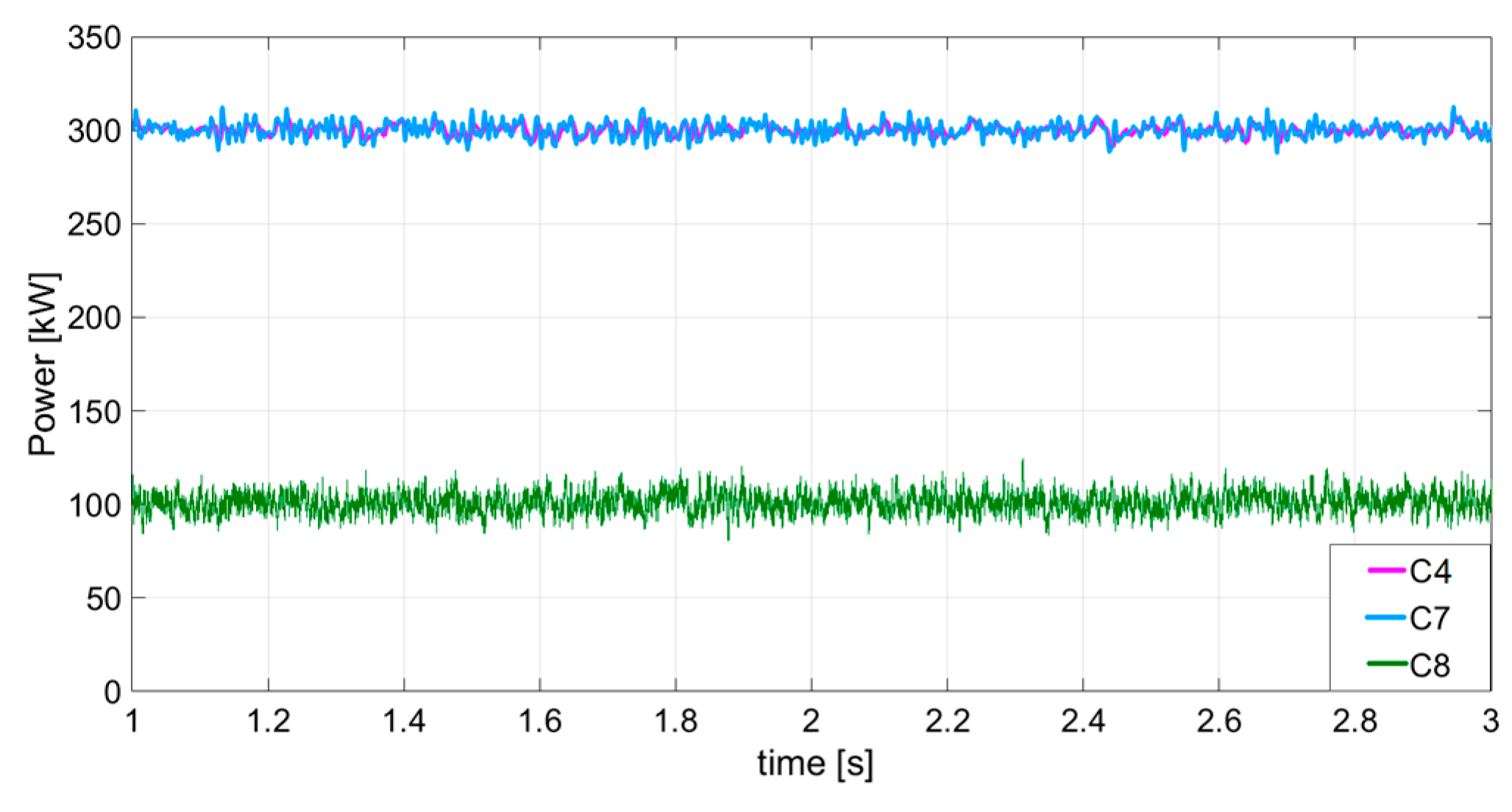
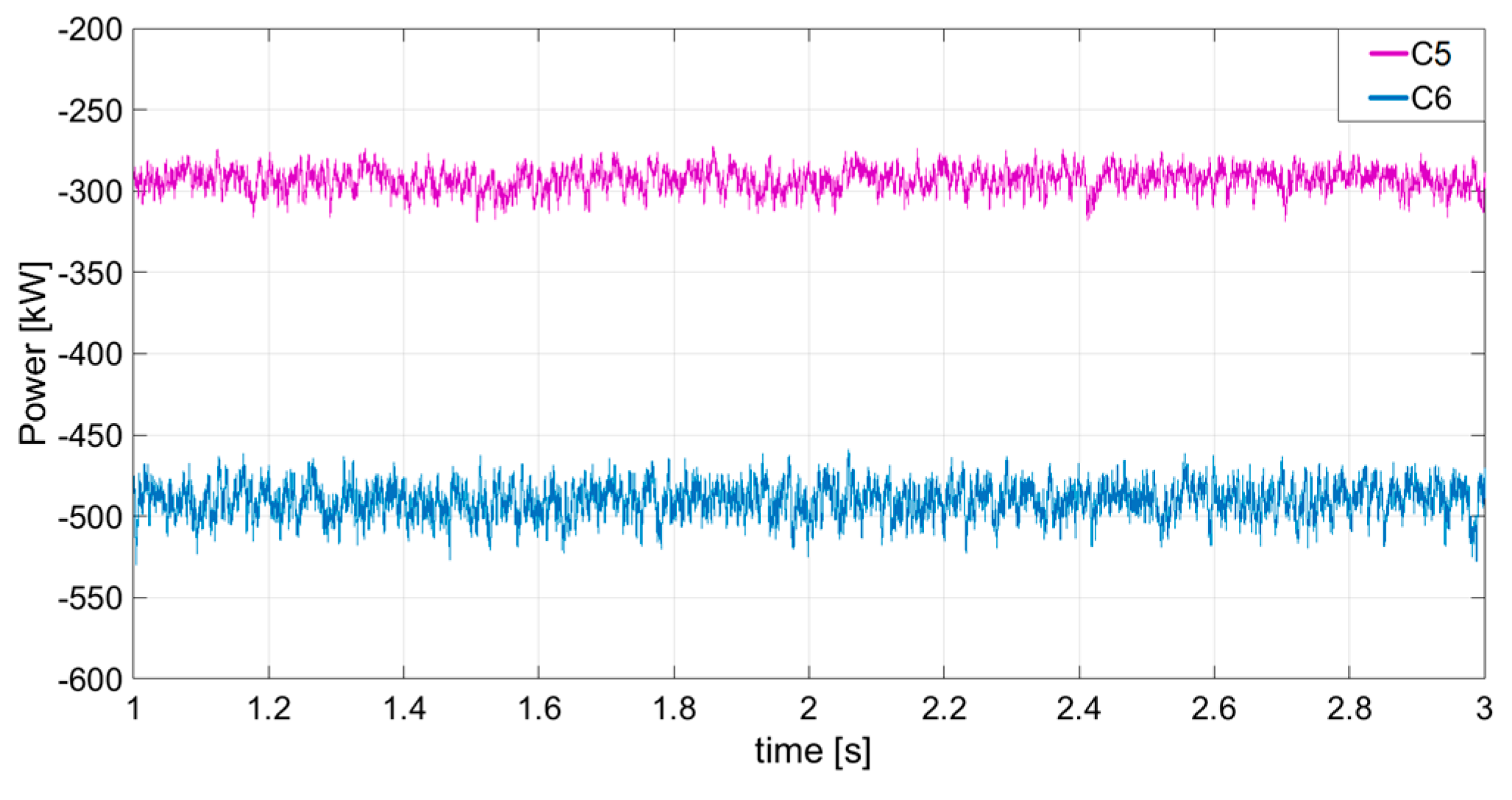
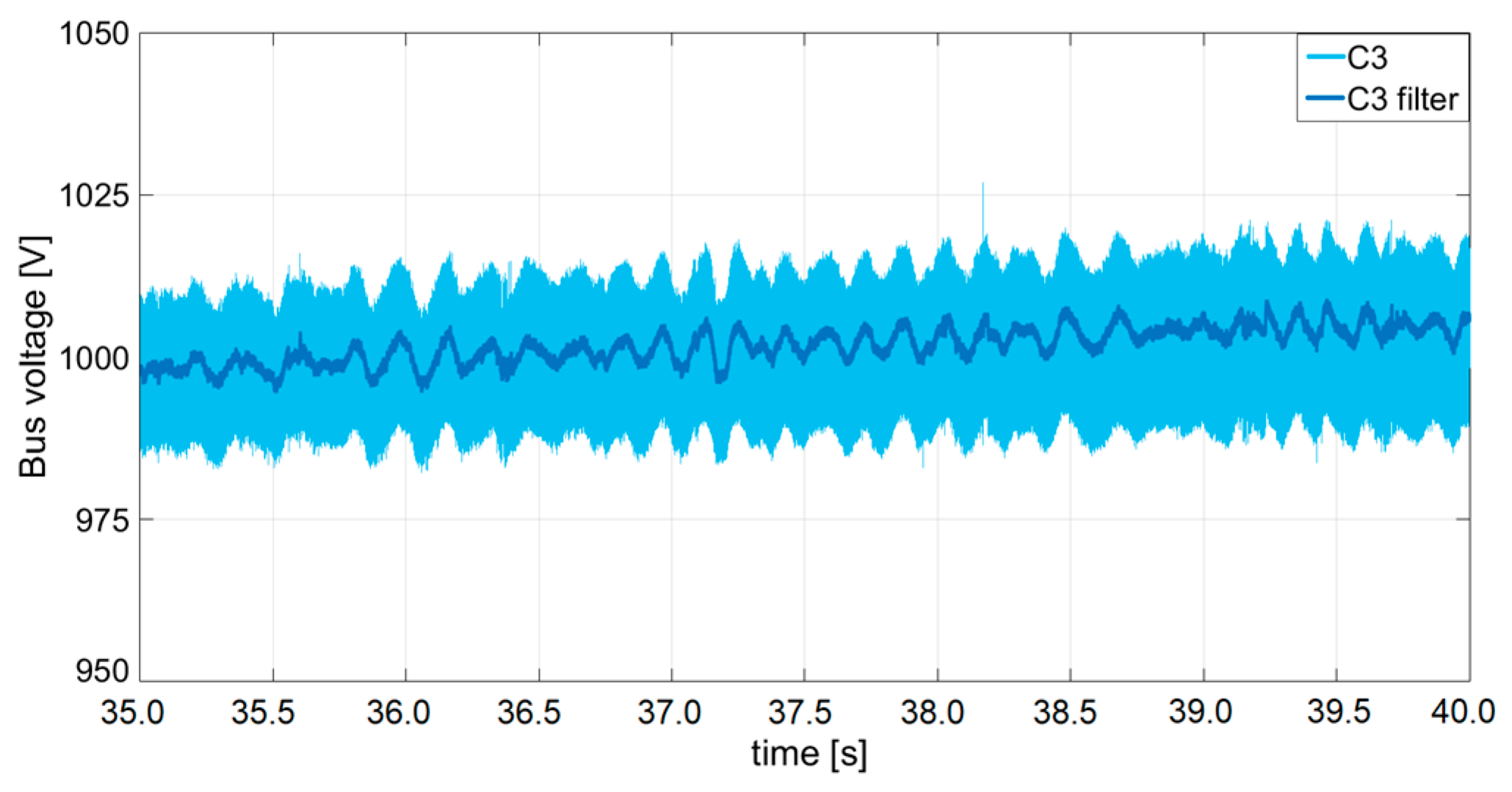
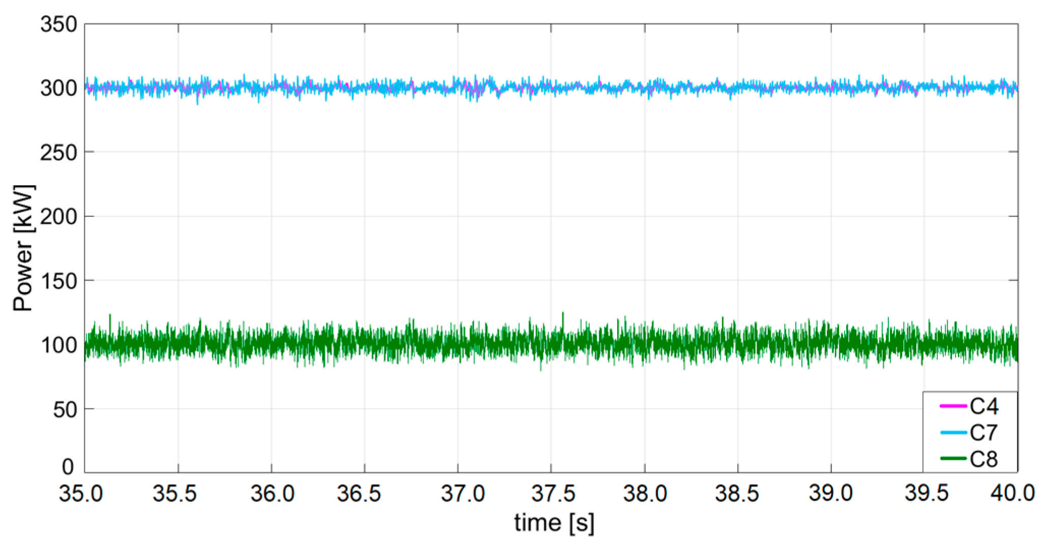
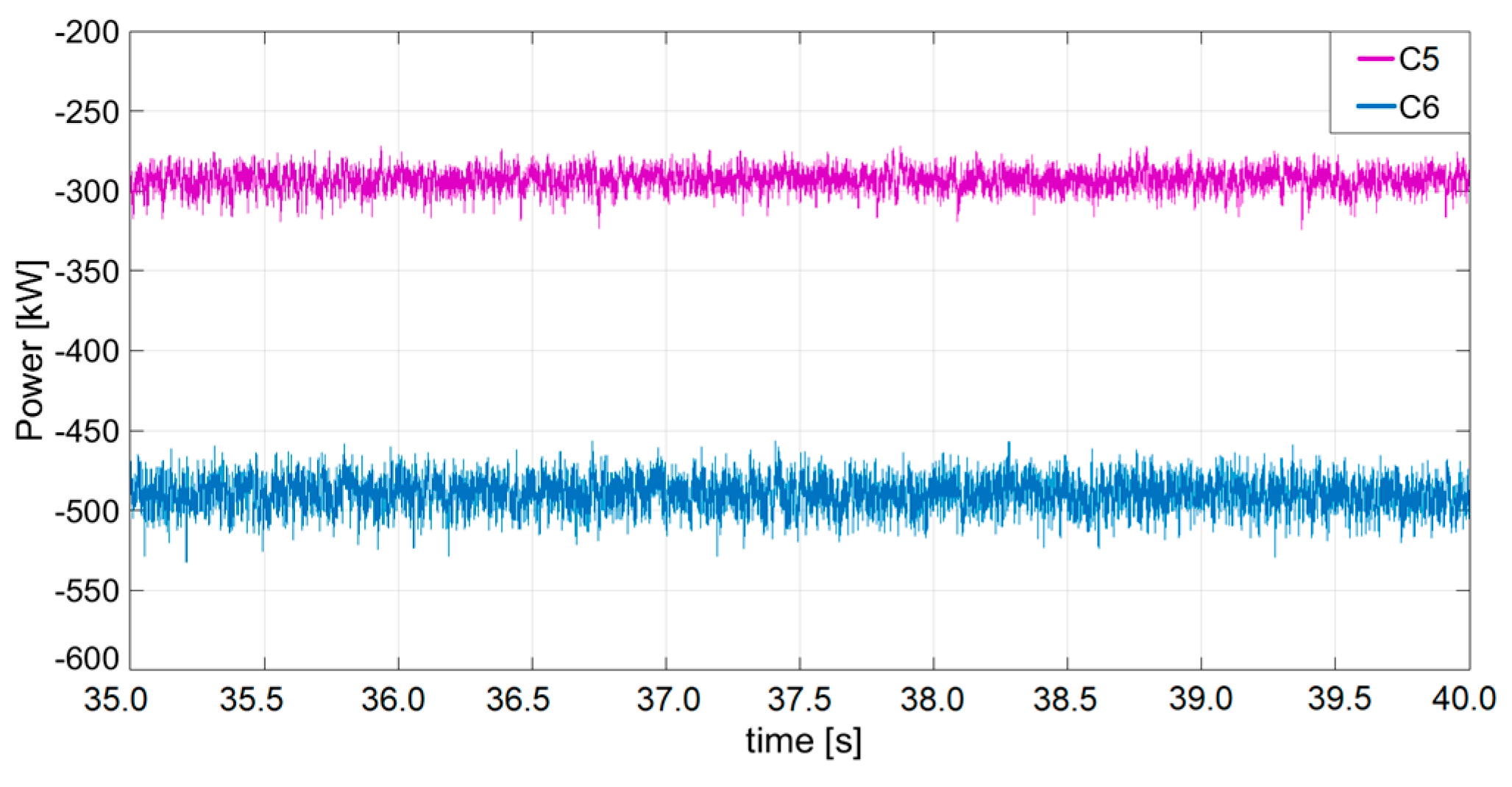
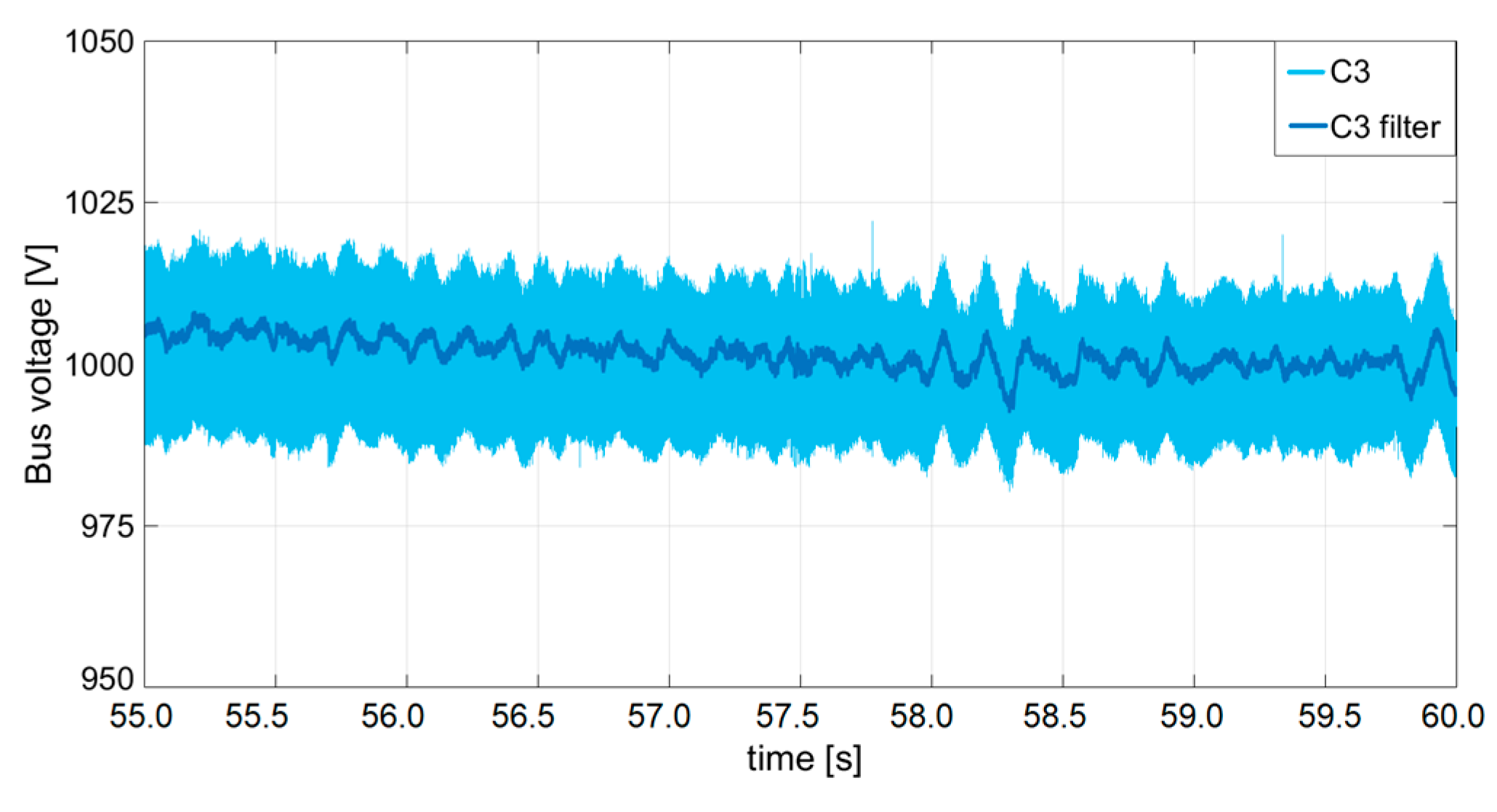
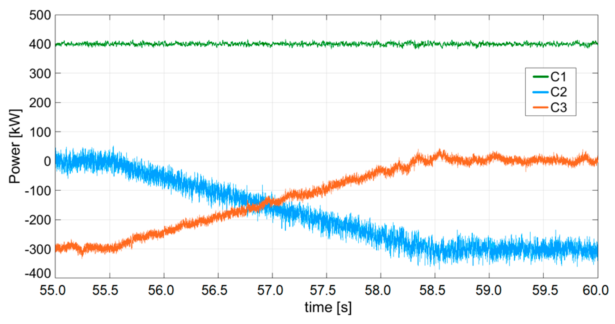
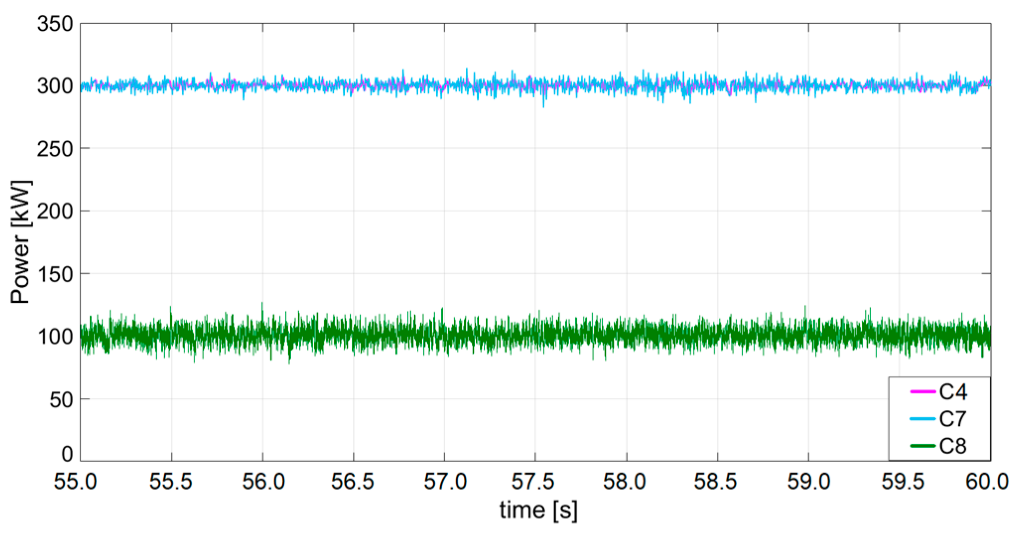
The proposed scenario envisions a coordinated power control strategy for the DC microgrid. During the 60 s under consideration, the controlled grid is anticipated to adjust its operation to harness renewable energy from the rising sun through PV sources. In the initial steady-state condition, during the night the C1 converter remains idle, and the main grid (C2 converter) supplies 100 kW to cater to two aggregated loads (800 kW) through the action of the C5–C6 converters. The remaining 700 kW is sourced from bidirectional operations of the C4–C7–C8 converters, utilizing the stored energy in the onboard batteries of the moored vessels. Starting at 1.2 s, the PMS intervenes to redirect the 100-kW supply to the C3 battery-converter, effectively eliminating the need to purchase energy from the main grid. Upon reaching the second steady-state at t = 3 s, an extended pause of 32.5 s is introduced to verify and ensure the availability of solar energy. At 35.5 s, the C1 power-controlled converter is engaged to supply 400 kW from the PV source, adhering to a ramp-rate of 100 kW/s. Once the second transient state concludes at 39.5 s, a portion of the PV energy (100 kW) is allocated to power the charging vessels, while the remaining 300 kW is stored in the microgrid battery. Following a dead-time of 16 s, the C2 power-controlled converter initiates a 100 kW/s ramp-rate to the main system at 55.5 s. Ultimately, at 58.5 s, the C2 converter starts selling its entire 300 kW of green power to the external grid, marking the completion of the battery’s buffering function.

4.3. Hardware in the Loop Platform

To validate the coordinated power control, the DC microgrid of the marina is simulated using the Typhoon HIL 604 real-time platform. Employing the Software-In-the-Loop approach, the eight controlled converters illustrated in Figure 3 are integrated into the schematic editor to assess the microgrid’s functionality. In this simulation environment, seven core couplings divide the numerical tasks into eight cores, ensuring real-time transients with a time-step of 1 μs. After compiling the system-control code, real-time emulations are executed to illustrate the regulated switching behavior of the power converters, as depicted in Figure 10, Figure 11, Figure 12, Figure 13, Figure 14, Figure 15, Figure 16, Figure 17, Figure 18, Figure 19, Figure 20 and Figure 21.

4.4. Tests on HIL Platform

The behavior of the DC microgrid during the night-to-day transition is illustrated through 12 figures, categorized into three groups to depict the voltage-power transients triggered by three significant actions of the PMS. The starting point of the test is a steady-state condition in which the main grid (through converter C2) is supplying the loads with 100 kW of power. Since the sun is starting to rise, the idea is to let the battery handle the transition (through converter C3), by changing the droop coefficients. Therefore, the first PMS activity involves the smooth inversion of droop coefficients on two parallel-controlled supplying converters, C2 and C3. In the night configuration, a large droop coefficient on C3’s voltage control resets the power contribution from the battery, while C2, with a tiny droop coefficient, forces the entire load supply from the external grid during no-sun hours. After the first transient, the droop values swap in about 0.4 s (Figure 11) to cut off the power from the main grid without consequences for the bus voltage (Figure 10). At 2 s, the battery autonomously provides the power requested by the loads (100 kW), and the bus voltage regulation is still delegated to the C2–C3 parallel-connected converters. Ships interfaced by C4–C7–C8 provide their power quota to the DC microgrid, as shown in Figure 12. In contrast, C5–C6 converters behave as loads while charging the battery on hosted vessels (Figure 13). After confirming the availability of PV energy, at 35.5 s, the PMS initiates the second transient. The C1 power-controlled converter begins supplying the system with a 100 kW/s ramp-rate. The battery inverts its operation, storing the 300-kW surplus energy at the end of PV entry. This operation change is evidenced by a slight increase in the filtered bus voltage value (about 1%), influenced by the input current to the BESS (Figure 14). Battery charging reaches a steady-state condition at 39.5 s (Figure 15). The coordinated control’s capability to avoid power perturbations is demonstrated in both supplying (Figure 16) and load converters (Figure 17). In the final transients, the PMS enforces a power injection into the external grid, indicated by the negative voltage droop in Figure 18. At 55.5 s, the available power from PV is dynamically split between the battery and the C2 converter (Figure 19). Now, the C2 converter is power-controlled to provide 300 kW after 3 s (i.e., 100 kW/s). The input power to the BESS is, accordingly, reduced to zero. Figure 20 and Figure 21 show no effects on the generating-load converter’s power, confirming the viability of the coordinated power control in managing the yacht marina DC microgrid. These tests have proven the efficacy of the power system design and control choices. What is particularly relevant is the use of a well-established and easy to implement control algorithm, which is the droop control. This control is beneficial for the stable operation of the power system (adding damping to the system), as can be seen in the voltage transients of Figure 10, Figure 14 and Figure 18. The other advantage is its ability to control the bus voltage without the need of an additional communication interface between converters. Therefore, if there is a sudden disconnection of a load, the system is able to operate continuously thanks to the automatic action of the C2 and C3 converters (e.g., see the transients in Figure 15 and Figure 19).

4.5. Results and Discussion

Before moving to conclusions, a summary discussing the effectiveness of the control choices is here provided. One of the main goals in a properly designed power system is to guarantee safe and continuous power supply to the loads. As is shown in Figure 13, Figure 17 and Figure 21, the load supply is always provided and guaranteed. Meanwhile, Figure 10, Figure 14 and Figure 18 shows that the bus voltage is inside the values suggested by the standards and the transient evolution of the voltage is always stable. Another goal of the control strategy is to exploit as much as possible the energy generated and available inside the marina; this is done in Figure 15 by switching the power supply from the external main grid to the BESS present in the microgrid. Then, when the sun is available, the PV source is both able to supply the desired loads and to recharge the battery (Figure 15). The final goal is to be able to sell energy to the main grid in order to provide economic benefits to the ship owners, which is achieved by changing the control mode of converter C3, as shown in Figure 19.

5. Conclusions

This paper has presented a coordinated power control system for a DC microgrid to improve the flexibility and resiliency of a green marina. The yacht marina of Porto San Rocco (Trieste, Italy) is taken as case study, and some techno-economic–environmental evaluations are made before emulating the controlled DC system on an HIL platform. From an analysis with Homer software, the PV installation presents a ROI between 7 and 10 years, depending on the additional presence of a dedicated storage system. Despite the larger ROI, the chosen configuration is finally oriented to land battery installation in order to ensure notable advantages for the power system operation (e.g., enhanced RES exploitation, flexibility, resiliency, redundancy, back-up functionality). Important efforts have been put into designing the PMS, which is responsible for ensuring efficient system management. The PMS logics on the DC microgrid are conceived and tested in a real-time emulation environment to increase correspondence with reality.
Significant efforts are invested into designing the PMS, serving as a centralized controller for efficient system management. The PMS logics on the DC microgrid are conceptualized and tested in a real-time emulation environment to enhance realism. This proposed PMS functions as a centralized controller to optimize marina operations. By dynamically adjusting control settings on multiple power converters based on power-voltage field measurements, the PMS ensures reliable vessel charging and bidirectional energy flow from hosted ships, thereby enhancing the marina’s sustainability. To demonstrate the controlled DC microgrid’s ability to manage sources, loads, and storage, various transients are simulated on the HIL platform. The emulation of a night-to-day transition illustrates how the PV plant not only provides sustainable energy for vessel charging, but also generates additional income for the marina by selling excess green energy to the main grid. This control strategy has only been applied to this specific case study and certainly needs more investigations for other operating conditions. Moreover, the strategy is not automatized and need the introduction of another control layer, and thus an Energy Management System (EMS), to properly optimize the energy flowing from/to the main grid. Future analyses will delve into studying the power flow throughout the day, developing strategies for days with no PV power output, and optimizing nighttime operations.

Author Contributions

Conceptualization, D.B., V.B. and G.S.; methodology, A.A.T., S.B. and M.D.F.; software, A.A.T., M.C. and M.D.F.; validation, S.B.; formal analysis, A.A.T. and M.D.F.; investigation, D.B., V.B. and G.S.; resources, A.A.T. and S.B.; data curation, D.B. and M.C.; writing—original draft preparation, A.A.T. and S.B.; writing—review and editing, A.A.T., D.B. and M.D.F.; visualization, V.B. and M.C.; supervision, G.S. All authors have read and agreed to the published version of the manuscript.

Funding

This research received no external funding.

Data Availability Statement

Data is contained within the article.

Acknowledgments

The authors would like to thank Typhoon HIL for providing the platform used in the development of this research work.

Conflicts of Interest

The authors declare no conflict of interest.

Abbreviations

RESRenewable Energy Sources
PVPhotovoltaic
BESSBattery Energy Storage System
PMSPower Management System
ZEMarZero Emission Marina
DSODistribution System Operator
MGMain Grid
AFEActive Front End
ROIReturn On Investment
HILHardware In the Loop

References

  1. Sun, Y.; Hu, Y.; Zhang, H.; Chen, H.; Wang, F.-Y. A Parallel Emission Regulatory Framework for Intelligent Transportation Systems and Smart Cities. IEEE Trans. Intell. Veh. 2023, 8, 1017–1020. [Google Scholar] [CrossRef]
  2. Wang, M.; Liu, K.; Choi, T.-M.; Yue, X. Effects of Carbon Emission Taxes on Transportation Mode Selections and Social Welfare. IEEE Trans. Syst. Man Cybern. Syst. 2015, 45, 1413–1423. [Google Scholar] [CrossRef]
  3. Gan, W.; Shahidehpour, M.; Yan, M.; Guo, J.; Yao, W.; Paaso, A.; Zhang, L.; Wen, J. Coordinated Planning of Transportation and Electric Power Networks With the Proliferation of Electric Vehicles. IEEE Trans. Smart Grid 2020, 11, 4005–4016. [Google Scholar] [CrossRef]
  4. Kanellos, F.D. Optimal Power Management With GHG Emissions Limitation in All-Electric Ship Power Systems Comprising Energy Storage Systems. IEEE Trans. Power Syst. 2014, 29, 330–339. [Google Scholar] [CrossRef]
  5. Hansen, J.F.; Wendt, F. History and State of the Art in Commercial Electric Ship Propulsion, Integrated Power Systems, and Future Trends. Proc. IEEE 2015, 103, 2229–2242. [Google Scholar] [CrossRef]
  6. Bosich, D.; Chiandone, M.; Sulligoi, G.; Tavagnutti, A.A.; Vicenzutti, A. High-Performance Megawatt-Scale MVDC Zonal Electrical Distribution System Based on Power Electronics Open System Interfaces. IEEE Trans. Transp. Electrif. 2023, 9, 4541–4551. [Google Scholar] [CrossRef]
  7. Fang, S.; Wang, Y.; Gou, B.; Xu, Y. Toward Future Green Maritime Transportation: An Overview of Seaport Microgrids and All-Electric Ships. IEEE Trans. Veh. Technol. 2020, 69, 207–219. [Google Scholar] [CrossRef]
  8. Qiu, J.; Tao, Y.; Lai, S.; Zhao, J. Pricing Strategy of Cold Ironing Services for All-Electric Ships Based on Carbon Integrated Electricity Price. IEEE Trans. Sustain. Energy 2022, 13, 1553–1565. [Google Scholar] [CrossRef]
  9. Smolenski, R.; Benysek, G.; Malinowski, M.; Sedlak, M.; Stynski, S.; Jasinski, M. Ship-to-Shore Versus Shore-to-Ship Synchronization Strategy. IEEE Trans. Energy Convers. 2018, 33, 1787–1796. [Google Scholar] [CrossRef]
  10. Guo, Z.; Wei, W.; Chen, L.; Dong, Z.Y.; Mei, S. Impact of Energy Storage on Renewable Energy Utilization: A Geometric Description. IEEE Trans. Sustain. Energy 2021, 12, 874–885. [Google Scholar] [CrossRef]
  11. Satpathi, K.; Ukil, A.; Nag, S.S.; Pou, J.; Zagrodnik, M.A. DC Marine Power System: Transient Behavior and Fault Management Aspects. IEEE Trans. Ind. Inform. 2019, 15, 1911–1925. [Google Scholar] [CrossRef]
  12. Xu, L.; Guerrero, J.M.; Lashab, A.; Wei, B.; Bazmohammadi, N.; Vasquez, J.C.; Abusorrah, A. A Review of DC Shipboard Microgrids—Part I: Power Architectures, Energy Storage, and Power Converters. IEEE Trans. Power Electron. 2022, 37, 5155–5172. [Google Scholar] [CrossRef]
  13. Son, Y.-K.; Lee, S.-Y.; Ko, S.; Kim, Y.-W.; Sul, S.-K. Maritime DC Power System With Generation Topology Consisting of Combination of Permanent Magnet Generator and Diode Rectifier. IEEE Trans. Transp. Electrif. 2020, 6, 869–880. [Google Scholar] [CrossRef]
  14. Kanellos, F.D. Real-Time Control Based on Multi-Agent Systems for the Operation of Large Ports as Prosumer Microgrids. IEEE Access 2017, 5, 9439–9452. [Google Scholar] [CrossRef]
  15. Rolán, A.; Manteca, P.; Oktar, R.; Siano, P. Integration of Cold Ironing and Renewable Sources in the Barcelona Smart Port. IEEE Trans. Ind. Appl. 2019, 55, 7198–7206. [Google Scholar] [CrossRef]
  16. Tavagnutti, A.A.; Bertagna, S.; Bosich, D.; Bucci, V.; Sulligoi, G. Coordinated Power Control for Flexible and Sustainable Operation of DC microgrids in Yacht Marinas. In Proceedings of the 2022 International Symposium on Power Electronics, Electrical Drives, Automation and Motion (SPEEDAM), Sorrento, Italy, 22–24 June 2022; pp. 689–694. [Google Scholar]
  17. Meng, L.; Shafiee, Q.; Trecate, G.F.; Karimi, H.; Fulwani, D.; Lu, X.; Guerrero, J.M. Review on Control of DC Microgrids and Multiple Microgrid Clusters. IEEE J. Emerg. Sel. Top. Power Electron. 2017, 5, 928–948. [Google Scholar]
  18. McCallum, P. Green Ports—Sustainable Port Development. In Ports 2022; American Society of Civil Engineers: Reston, VA, USA, 2022; pp. 592–600. [Google Scholar]
  19. Jugović, T.P.; Agatić, A.; Gračan, D.; Šekularac-Ivošević, S. Sustainable activities in Croatian marinas—Towards the “green port” concept. Sci. J. Marit. Res. 2022, 36, 318–327. [Google Scholar]
  20. Ahmad, N.B.; Othman, M.R.; Saadon, M.S.I.; Nor, D.A.M. Sustainable Development Goal of the Recreation Port: The Case Study of the Duyong Marina & Resort, Terengganu, Malaysia. J. Crit. Rev. 2020, 7, 1449–1454. [Google Scholar]
  21. Benevolo, C. Turismo Nautico: Una sfida per il distination management. Riv. Sci. Tur. 2010, 1, 105–129. [Google Scholar]
  22. Bucci, V.; Marinò, A.; Bosich, D.; Sulligoi, G. The design of a slow-cruising superyacht with zero emission navigation and smart berthing modes. In Proceedings of the 2014 Ninth International Conference on Ecological Vehicles and Renewable Energies (EVER), Monte-Carlo, Monaco, 25–27 March 2014; pp. 1–8. [Google Scholar]
  23. Braidotti, L.; Bertagna, S.; Marinò, A.; Bosich, D.; Bucci, V.; Sulligoi, G. An Application of Modular Design in the Refitting of a Hybrid-electric Propelled Training Ship. In Proceedings of the 2020 AEIT International Annual Conference (AEIT), Catania, Italy, 23–25 September 2020; pp. 1–6. [Google Scholar]
  24. Skorobogatova, N. Sustainable Development of an Enterprise Under Industry 4.0 Conditions. In Proceedings of the 2019 International Conference on Creative Business for Smart and Sustainable Growth (CREBUS), Sandanski, Bulgaria, 18–21 March 2019; pp. 1–5. [Google Scholar]
  25. Lamberti, T.; Sorce, A.; Di Fresco, L.; Barberis, S. Smart port: Exploiting renewable energy and storage potential of moored boats. In Proceedings of the OCEANS 2015-Genova, Genova, Italy, 18–21 May 2015; pp. 1–3. [Google Scholar]
  26. Banaei, M.; Rafiei, M.; Boudjadar, J.; Khooban, M.-H. A Comparative Analysis of Optimal Operation Scenarios in Hybrid Emission-Free Ferry Ships. IEEE Trans. Transp. Electrif. 2020, 6, 318–333. [Google Scholar] [CrossRef]
  27. La Nautica in Cifre 2020/2021; Confindustria Nautica: Genova, Italy; Fondazione Edison: Milano, Italy, 26 February 2021.
  28. Electric Boat and Ship Market—Growth, Trends, COVID-19 Impact, and Forecasts (2023–2028); Research and Markets: Dublin, Ireland, 2023.
  29. Blaabjerg, F.; Yang, Y.; Kim, K.A.; Rodriguez, J. Power Electronics Technology for Large-Scale Renewable Energy Generation. Proc. IEEE 2023, 111, 335–355. [Google Scholar] [CrossRef]
  30. Vandoorn, T.L.; Vasquez, J.C.; De Kooning, J.; Guerrero, J.M.; Vandevelde, L. Microgrids: Hierarchical Control and an Overview of the Control and Reserve Management Strategies. IEEE Ind. Electron. Mag. 2013, 7, 42–55. [Google Scholar] [CrossRef]
  31. Yi, Z.; Dong, W.; Etemadi, A.H. A Unified Control and Power Management Scheme for PV-Battery-Based Hybrid Microgrids for Both Grid-Connected and Islanded Modes. IEEE Trans. Smart Grid 2018, 9, 5975–5985. [Google Scholar] [CrossRef]
  32. Egwebe, A.M.; Fazeli, M.; Igic, P.; Holland, P.M. Implementation and Stability Study of Dynamic Droop in Islanded Microgrids. IEEE Trans. Energy Convers. 2016, 31, 821–832. [Google Scholar] [CrossRef]
  33. Mokhtar, M.; Marei, M.I.; El-Sattar, A.A. An Adaptive Droop Control Scheme for DC Microgrids Integrating Sliding Mode Voltage and Current Controlled Boost Converters. IEEE Trans. Smart Grid 2019, 10, 1685–1693. [Google Scholar] [CrossRef]
  34. Tavagnutti, A.A.; Bosich, D.; Sulligoi, G. Active Damping Poles Repositioning for DC Shipboard Microgrids Control. In Proceedings of the 2021 IEEE Electric Ship Technologies Symposium (ESTS), Arlington, VA, USA, 3–6 August 2021; pp. 1–8. [Google Scholar]
  35. Mutarraf, M.U.; Terriche, Y.; Niazi, K.A.K.; Su, C.-L.; Vasquez, J.C.; Guerrero, J.M. Battery Energy Storage Systems for Mitigating Fluctuations Caused by Pulse Loads and Propulsion Motors in Shipboard Microgrids. In Proceedings of the 2019 IEEE 28th International Symposium on Industrial Electronics (ISIE), Vancouver, BC, Canada, 12–14 June 2019; pp. 1047–1052. [Google Scholar]
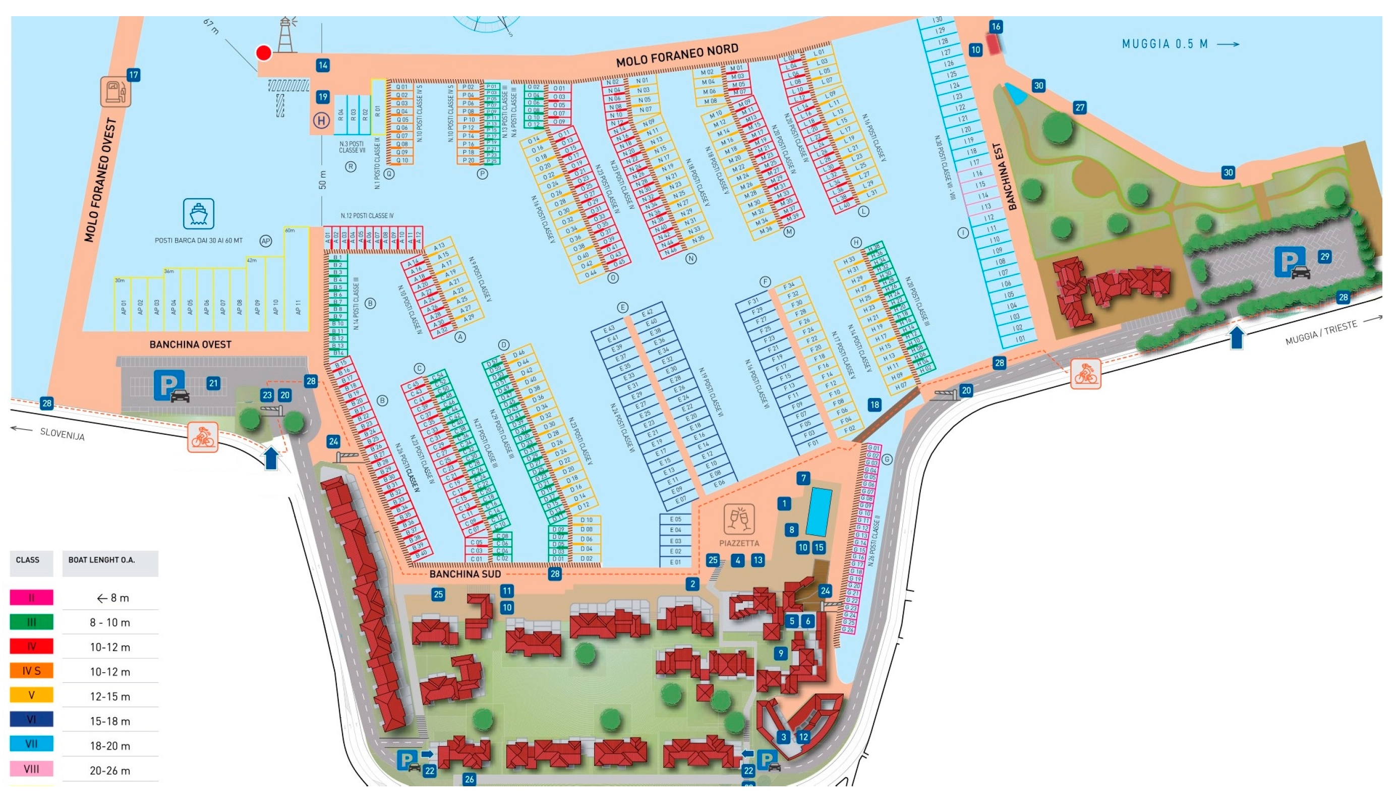
Figure 1. Yacht marina in Porto San Rocco, Muggia, Trieste (Italia) (https://www.portosanrocco.it/marina/planimetria/, accessed on 20 January 2024).
Energies 17 00521 g001
Figure 2. Propulsion and electrical generation systems for pleasure craft.
Energies 17 00521 g002
Figure 3. The controlled 1 kV-DC microgrid for the green marina [16]. Reprinted with permission from Ref. [16]. Copyright 2022, IEEE.
Energies 17 00521 g003
Figure 4. Optimized solution from Homer software.
Energies 17 00521 g004
Figure 5. Daily radiation for Porto San Rocco (Muggia, Trieste).
Energies 17 00521 g005
Figure 6. Economic comparison between standard–hybrid–PV solutions.
Energies 17 00521 g006
Figure 7. Electric energy balance for PV solution.
Energies 17 00521 g007
Figure 8. Energy purchased from grid for PV solution.
Energies 17 00521 g008
Figure 9. Energy sold to grid for PV solution.
Energies 17 00521 g009
Figure 10. Storage system voltage (first transient) [16]. Reprinted with permission from Ref. [16]. Copyright 2022, IEEE.
Energies 17 00521 g010
Figure 11. Upper converter’s power (first transient) [16]. Reprinted with permission from Ref. [16]. Copyright 2022, IEEE.
Energies 17 00521 g011
Figure 12. Generating converter’s power (first transient) [16]. Reprinted with permission from Ref. [16]. Copyright 2022, IEEE.
Energies 17 00521 g012
Figure 13. Load converter’s power (first transient) [16]. Reprinted with permission from Ref. [16]. Copyright 2022, IEEE.
Energies 17 00521 g013
Figure 14. Storage system voltage (second transient) [16]. Reprinted with permission from Ref. [16]. Copyright 2022, IEEE.
Energies 17 00521 g014
Figure 15. Upper converter’s power (second transient) [16]. Reprinted with permission from Ref. [16]. Copyright 2022, IEEE.
Energies 17 00521 g015
Figure 16. Generating converter’s power (second transient) [16]. Reprinted with permission from Ref. [16]. Copyright 2022, IEEE.
Energies 17 00521 g016
Figure 17. Load converter’s power (second transient) [16]. Reprinted with permission from Ref. [16]. Copyright 2022, IEEE.
Energies 17 00521 g017
Figure 18. Storage system voltage (third transient) [16]. Reprinted with permission from Ref. [16]. Copyright 2022, IEEE.
Energies 17 00521 g018
Figure 19. Upper converter’s power (third transient) [16]. Reprinted with permission from Ref. [16]. Copyright 2022, IEEE.
Energies 17 00521 g019
Figure 20. Generating converter’s power (third transient) [16]. Reprinted with permission from Ref. [16]. Copyright 2022, IEEE.
Energies 17 00521 g020
Figure 21. Load converter’s power (third transient) [16]. Reprinted with permission from Ref. [16]. Copyright 2022, IEEE.
Energies 17 00521 g021
Table 1. Battery pack capacity for traditional pleasure craft.
Type of Pleasure VesselApproximate Battery Packs Capacity (kWh)
Up to 10 m5.0
From 10.01 m to 12.008.0
From 12.01 m to 18.0012.00
From 18.01 m to 24.0025.00
From 24.01 m to 35.0075.00
Table 2. Battery pack capacity for hybrid pleasure craft.
Type of Pleasure VesselApproximate Battery Packs Capacity (kWh)
Up to 10 m15.0
From 10.01 m to 12.0021.0
From 12.01 m to 18.0042.00
From 18.01 m to 24.00350.00
From 24.01 m to 35.00700.00
From 35.01 m to 60.001500.00
Over 60.00 m3000.00
Table 3. Load Profile in DC Yacht Marina.
Profile
Up to 10 m
PowerMonth
123456789101112
HI%101020254070908060352010
kW325325650813130022752925260019501138650325
LO%101015203560757050301510
kW32532548865011381950243822751625975488325
Disclaimer/Publisher’s Note: The statements, opinions and data contained in all publications are solely those of the individual author(s) and contributor(s) and not of MDPI and/or the editor(s). MDPI and/or the editor(s) disclaim responsibility for any injury to people or property resulting from any ideas, methods, instructions or products referred to in the content.