Abstract
The objective of the investigation was to increase the effectiveness of damage detection in the stator of the squirrel-cage induction machine. The analysis aimed to enhance the operational trustworthiness of the squirrel-cage induction machine by employing nonintrusive diagnostic methods based on a current signal and modern artificial intelligence methods. The authors of the study introduced a diagnostic technique for identifying multiphase interturn short circuits of stator winding. These short circuits are one of the most common faults in induction machines. The proposed method focusses on deriving a diagnostic signal from the phase-current waveforms of the machine. The noninvasive nature of the diagnostic technique presented is attributed to the application of the field model of electromagnetic phenomena to determine the diagnostic signal. For this purpose, a field model of a squirrel-cage machine was developed. The waveforms of phase currents obtained from the field model were used as input into an elaborated machine failure neural classifier. A deep neural network was used to develop a neural classifier. The effectiveness of the developed classifier has been experimentally verified, and the obtained results have been presented, concluded, and discussed. The scientific novelty presented in the article is the presentation of research results on the use of a neural classifier to detect damage in all phases of the stator winding at an early stage of its appearance. The features of this type of damage are very difficult to observe in signal waveforms such as a phase current or torque.
1. Introduction
Induction machines are a critical component of many industrial processes and their reliability is crucial to ensure the efficiency and productivity of those processes [1,2,3]; the trend towards electric vehicles may result in even greater interest in this type of electric motor [4,5,6,7,8]. Induction machines are commonly used in industry due to their simplicity, reliability, efficiency, cost effectiveness, robustness, and ease of control using variable frequency drives and other control systems [9,10]. However, diagnosing induction machine failures can be challenging due to the complex interactions between electrical, mechanical, and environmental factors. One of the most common faults of induction machines is interturn short circuits. These short circuits in induction machines can be caused by a variety of factors. The most important causes of short circuits include ageing and wear of the insulation, electrical overstress, such as sudden surges or transients in the voltage supply, thermal stress from high temperatures, mechanical stresses, and vibrations, or overloading the machine beyond its rated values. Of course, regular maintenance and diagnostics of the machine can help to prevent the occurrence of interturn short circuits.
In research related to the development and analysis of reliable technical solutions, field models are being increasingly used, because of their credibility. Among others, the finite-element method has become widely used in the modelling of a variety of technical devices. Due to its versatility, FEM has been successfully used to solve complex problems, including for modelling magneto-optics and in stress simulations for the prediction of fatigue life of a radial cylindrical roller bearing, as well as, for example, in studying temperature [11] and strain fields in gas-foil bearings and modelling a deep-hole drilling tool. Numerical models exploiting FEM are also applied to the study of electromagnetic phenomena in electrical machines. Field and field circuit models exploiting FEM have been successfully applied in the analysis and synthesis of many different types of electromechanical transducers, such as induction [12,13,14] and synchronous machines [15,16,17], switched reluctance motors [18,19,20], stepper motors, brushless direct current machines, and linear motors, as well as in wireless power transfer systems, magnetic field excitation systems, and other electromagnetic converters.
The most popular and widespread diagnostic methods used in the detection and classification of interturn short circuits of electrical machines are motor current signature analysis (MCSA) [21,22,23,24], motor vibration signature analysis (MVSA) [25,26,27], the Park vector approach (PVA) [28,29,30], or wavelet transform (WT) [31,32]. These techniques allow for noninvasive analysis of a diagnostic signal without having to turn off the machine, and thus without interrupting the current operating state of the machine. For this reason, the authors of the present article used phase current waveforms as a diagnostic signal. However, the use of the above-mentioned diagnostic methods requires a good understanding of theory and practice in the fields of signal processing and electrical machines themselves. The influence of the human factor becomes even more significant if the subject of interest fails in its early stage of occurrence.
Current research in the field of diagnostics of electrical machines is increasingly focused on the use of machine-learning elements in the diagnostic process. Earlier research involved the use of simple structures such as multilayer perceptrons. Currently, due to the increasing amount of data to be processed and their increasingly complex structure, the use of simple perceptron networks is difficult and, in some cases, almost impossible due to the problem of gradient decay in the case of deeper multilayer perceptron structures. Therefore, more models of multicouple neural networks, such as a convolutional neural network (CNN) [33,34,35], a generative adversarial network (GAN) [36,37,38], and a long-short-term memory network (LSTM) [39,40,41], were used in the diagnostic process. Unfortunately, with the increasing complexity of neural network models, the number of network parameters that can affect network results is increased. In the case of deep networks, in addition to the basic parameters such as the number of neurones in layers or the number of layers, there are additional hyperparameters in the tuning process, e.g., the number of kernels in convolutional layers, kernel step, dropout rate, padding, and many others. In the case of networks with moderately complex structure, researchers decide to empirically select network parameters [42], but with increasing network complexity, empirical selection of parameters requires a lot of experience and intuition preceded by many years of research into the deep structures of neural networks in issues related to the diagnostics of electrical machines. In order to simplify the tuning of deep neural network models in the diagnosis of induction machines, the authors present an approach using the grid search method. In the results of the research presented, precision was used as a metric.
Due to the fact that interturn short circuits, especially at an early stage of their occurrence (a small number of shorted turns), do not significantly affect the phase current waveforms, they are difficult to detect and unambiguously interpret. In this study, the authors propose a novel approach that combines the field model and deep neural networks to enhance the accuracy and efficiency of the induction machine diagnostic process. First, a machine field model was developed, which allows for the simulation of machine behaviour under various fault conditions. Then, the data from the model were used to train a deep neural network. The presented approach can improve the accurate classification of different levels and types of faults, for example bearing failures, shaft unbalance, cage bars being broken, or end rings being broken.
2. Materials and Methods
To obtain a diagnostic signal for the purposes of training deep neural networks, a field model of a squirrel-cage induction machine was elaborated. The developed model has been modified in such a way as to enable one to simulate selected failure machine operating states. The failure machine operating state is understood as failure of the stator winding in the form of multiphase interturn short circuits. One of the stages of creating the field model was to develop a circuit model of the machine. This type of damage includes a short circuit independently in all phases of the stator winding. Therefore, their modelling was used in all phases. The model of the machine, taking into account the multiphase interturn short circuits in the stator winding, is shown in Figure 1. In Figure 1, the number of shorted turns is marked as N, the winding resistance as R, and the winding inductance as L for each phase. The motor model was developed based on the motor with the rated data presented in Table 1.

Figure 1.
Model of a stator winding with multiphase interturn short circuit.

Table 1.
Induction machine parameters.
The Ansys Maxwell 2023 R2 environment was used to develop a model of the field induction motor. The developed model takes into account the phenomenon of saturation. During model development, the actual magnetisation characteristics of the materials were introduced for the magnetic materials of the stator, rotor, and shaft of the considered machine. The calculations were carried out for a constant ambient and operating temperature that was appropriately 20 and 40 °C. The model allows calculations to be performed not only for a healthy machine, but also for modelling damage in the form of multiphase interturn short circuits. Modifying the model to enable the simulation of multiphase interturn short circuits results in the division of the stator phase windings, which in turn affects both the resistances and inductances of the relevant machine circuits. Below is a matrix describing the resistances and inductances of the stator winding for the damaged machine. To simplify and shorten the notation, the following entry will concern failure in one phase of the machine. For the remaining phases, the methodology for determining the resistance and inductance of individual circuits is analogous, and only appropriate shifts must be taken into account.
where is the resistance of the damaged part of the stator winding of phase A, is the resistance of the heathy part of the stator winding of phase A, is the stator phase B resistance, and is the stator phase C resistance.
where , , , and are the leakage inductance of the windings of individual stator circuits’ inductance, , , , and are the main self-inductances of the stator circuits, and , , , , , and are the main mutual inductances of the stator.
Based on the circuit model of the machine and the technical documentation, a field model of the machine was developed. The common finite-element method was used to solve the magnetic field equations in the developed model. In the discretization process, the model was divided into triangular finite elements. In order to assess the quality of the discretising mesh, Table 2 presents the number of elements, as well as the minimum, maximum, and average values of their dimensions and surface areas in individual subareas. Using the developed model, simulation calculations of the induction machine were performed, taking into account failures in each phase of winding.

Table 2.
Induction machine model parameters.
3. Classification of Stator Winding Damage
Detecting short circuits in the winding of an induction machine is a very difficult task. This is due to the fact that the impact of a small number of shorted turns on the machine operation is difficult to observe in the diagnostic signal waveform. Example waveforms of the phase current in the case of a healthy and damaged machine (short-circuit configuration: NfA = 1, NfB = 1, NfC = 5) are shown in Figure 2 and Figure 3, respectively. To classify this type of damage based on the analysis of the phase current waveform of the stator winding, a system was developed in which the role of the classifier was entrusted to a deep neural network. The developed network enables the detection of interturn short circuits in three phases of the stator winding of a squirrel-cage machine. The task of the network is to determine the degree of failure of the stator winding. A stator failure involves interturn faults in the range from 0 to 10 shorted turns for each phase, resulting in 1000 classes for classification by a deep neural network (DNN). The data obtained from the developed field model of the induction machine containing 73,230 samples were used in the learning process. The data were divided into three sets: training, validation, and test in the proportions of 60:20:20. Phase current waveforms were used as input data for the DNN. One of the most commonly used deep neural network structures in classification problems is convolutional neural networks. Due to the ability to extract special features and reduce the size of data, they are able not only to detect changes in the signal that may be unnoticeable to an expert but also to reduce the computational complexity of the model. Therefore, due to the nature of the problem of classifying the degree of stator winding failure, convolutional neural networks were used in the present work.
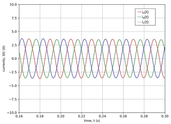
Figure 2.
Phase current waveforms of a healthy induction machine.
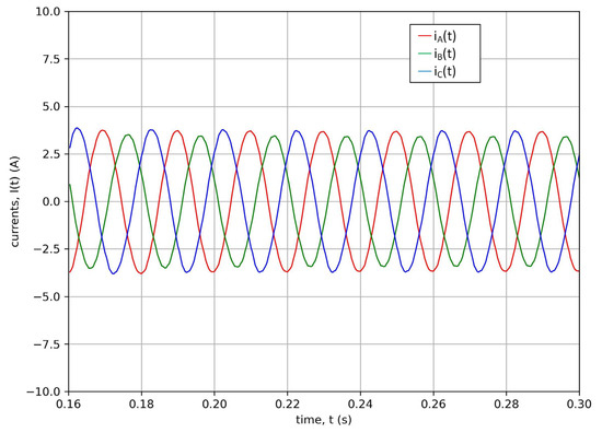
Figure 3.
Phase current waveforms of a damaged induction machine.
The article focuses on diagnostics based on current waveforms and does not mention spectral diagnostics because of the need to apply a transformation from the time domain to the frequency domain. One of the goals of using neural classifiers in the early diagnosis of the stator winding is to detect the fault as quickly as possible. Of course, the use of spectral analysis can have a positive impact on the quality of classification, but additional transformation during diagnostics while the machine is running can also slow down the decision-making process itself, which is why the article focusses on raw data.
The occurrence of an interturn short circuit in the stator winding causes a change in the equivalent circuit of the stator winding. As a result of an interturn short circuit, the phase winding is divided into two parts. The first part contains shorted turns, while the second part contains the rest of the phase winding turns. This division causes changes in the magnetic field distribution and, consequently, in the induced electromotive force in the winding, the current flowing in the winding, and finally the torque. The difficulty is that, in the case of a small number of shorted turns, changes in the waveforms of these signals are difficult to notice. Therefore, a deep neural network was used to detect the occurrence of a short circuit in the stator winding circuit based on phase current waveforms. CNN networks, thanks to their convolutional layers, are able to extract changes in the current signal of an induction machine, which, in the case of interturn short circuits at an early stage of their occurrence, are very difficult or even impossible to detect using other methods due to their small impact on the current value. Due to the use of networks with convolutional layers, the presence of an expert in the field of electrical machine diagnostics is not required, as well as complicated normalisation of training data when preparing the training set. This may affect the general simplicity of using this type of network on a larger scale in the diagnosis of stator windings of electrical machines. Currently, scientific publications focus on the use of neural networks in the diagnostics of the stator winding of electric machines, but mostly they focus on failure in one phase of the machine, which makes a slight number of short-circuit configurations and therefore the computational complexity and the problem of multi-class classification of interturn short circuits are less complicated. In the case of the considered multiphase short circuits, the classification of the degree of stator failure requires a classification of up to 1000 classes, which significantly complicates the classification of failure. The article, unlike other publications, presents the use of deep learning in the problems of multiphase interturn short circuits. The issue of multiphase interturn short circuits significantly affects the level of complexity of the classification problem, which makes the influence of hyperparameters of the neural network even more important in decision-making, and therefore the selection of the values of these parameters a priori may be even more complicated. In the article, a deterministic approach was proposed for tuning the network for the classification of multiphase interturn faults, which involves searching a certain variable space to determine the best configuration of hyperparameters for the multiphase interturn short-circuit task.
Due to the nature of the problem under consideration, which is multiclass classification, and the nature of the input data to the CNN-type network, the loss function was defined by the formula:
where is the vector of weights, is the expected value, and is the predicted value.
To avoid the phenomenon of overfitting, the loss function presented by Formula (1) has been modified as follows:
where is a term related to L2 normalization.
On the basis of research, the basic structure of the network was selected. In the next stage of research, its hyperparameters were modified. The modification included tuning hyperparameters such as: optimiser, learning rate, dropout rate for dropout layers, the number of kernels in convolutional layers, and the number of neurones in the dense layer. The diagram of the diagnostic process with the basic structure of the network for the diagnosis of the stator winding of an induction machine is shown in Figure 4, while the values of its constant parameters are shown in Table 3.

Figure 4.
Diagram of the diagnostic process.

Table 3.
The parameters of the neural network.
As can be seen in Figure 4, the diagnostic process used can be divided into stages. The first was to develop a model using the finite-element method, taking into account failure of the stator winding. The second stage was to prepare input data to the network based on the results obtained from the model. The next stage was to develop a network model and carry out the training process based on the input data. The last stage was the analysis of the classifier results.
As mentioned, during the research, the hyperparameters of the model were tuned. The tuning process was divided into several stages. In the first stage, such parameters as the optimiser, learning rate (lr), and dropout rate (dr) were tuned. The tuning was carried out with a constant number of kernels in the convolutional layers and neurones in the dense network layers. The tuning was carried out using the grid search method, which, unlike, for example, the random search or Bayesian optimisation method, is a more time-consuming method due to the greater demand for computing power, but at the same time allows for better tuning results. The grid search method consists of determining the variability range of the selected variables and then carrying out the network learning process for the ‘peer-to-peer’ configuration. The tuning parameters and the range of their variability are presented in Table 4. During tuning, in the first stage, 64 kernels were assumed in the first and the second convolutional layers, 128 kernels in Layers 3 and 4, and 128 units in the dense layer. In the next stage of the investigation, the influence of these parameters on the failure classification results was examined.

Table 4.
Hyperparameters values during first turning.
The optimisers mentioned in Table 4 update the model weights according to the following formulas:
SGD:
wherein
where are the weights in the next step, are the weights in the current step, is the learning rate, represents the aggregate of gradients in the current step, is the moving average parameter, is the aggregate of gradients in the previous step, and is the loss function.
RMSProp:
wherein
where is the sum of the square of current gradients, is the moving average parameter, and is the sum of the square of previous gradients.
ADAM:
wherein
3.1. Tuned CNN—Stage I
The results of the optimisation of the network parameters during the first stage are shown in Figure 4, Figure 5 and Figure 6 and Table 5.
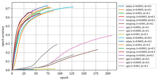
Figure 5.
Value of the metric as a function of the epoch (Stage I).
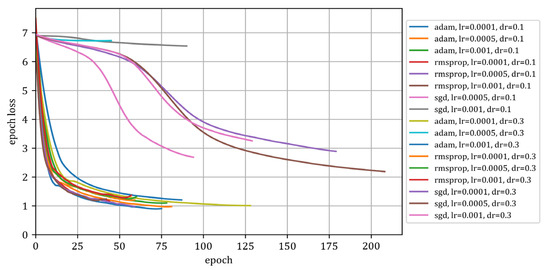
Figure 6.
Value of the loss function in the epoch function (Stage I).

Table 5.
Hyperparameter tuning results in Stage I.
Figure 5, Figure 6 and Figure 7 show the results of the network training process. Figure 5 shows how the metric value changed in subsequent epochs while training the model. Figure 6 shows the decline in the loss function as a function of the epochs, while Figure 7 graphically presents the considered configurations of the network hyperparameters used during the first stage of network tuning. In Figure 7, the colours do not have much meaning and are not specified for the purpose of presenting the data. Figure 7 shows how the results are distributed for individual configurations.
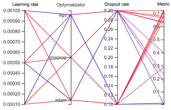
Figure 7.
Hyperparameter configurations (Stage I).
The research carried out calculations of the metric value depending on changes in three parameters: dropout rate, learning rate, and the type of optimiser used. The calculation results presented as a function of three variables in one figure are illegible. For a more accurate presentation of the results, Figure 8, Figure 9, Figure 10, Figure 11, Figure 12, Figure 13, Figure 14, Figure 15 and Figure 16 group the data according to the optimiser, learning rate, and dropout rate, respectively. Due to the multitude of hyperparameters that were taken into account during the network training process for multiphase interturn short circuits, it was decided to divide the chapter into subchapters. Attempts to aggregate the data into summary charts resulted in less readability.
3.1.1. Impact of Optimiser on Multiphase Interturn Short-Circuit Classification
The paper presents the influence of the choice of optimiser on the quality of classification of multiphase interturn short circuits in the stator winding of an induction machine. Three gradient descent-based optimisers were considered: SGD, RMSProp, and ADAM. The influence of optimiser selection in the diagnostic process of multiphase interturn short circuits is shown below:
Figure 8 shows the classification results of the neural network developed with the SGD optimiser. As can be seen in the case of the SGD optimiser, the overall quality of fault classification is unsatisfactory and, at best, the metric value does not exceed even 40% of correct fault classifications.
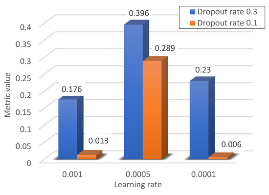
Figure 8.
Metric values for the SGD optimiser.
The results for the network with the RMSProp optimiser shown in Figure 9 show that, unlike the SGD algorithm, with the RMSProp optimiser better results were obtained for all considered hyperparameter configurations.
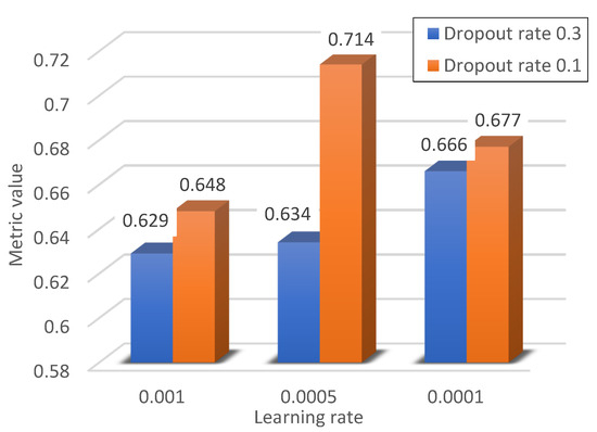
Figure 9.
Metric values for the RMSProp optimiser.
However, the results for the ADAM optimiser show that in the case of this optimiser, the selection of the learning rate in most cases did not have such a large impact on the final classification results. Only in the case of a learning rate of 0.0005 and a dropout value of 0.3, the result is clearly worse. This problem does not have to result from incorrectly selected values of the learning rate and dropout for the short-circuit classification problem but may be caused, for example, by incorrectly selected initial values of the model weights, which could cause the algorithm to become stuck in the local minimum. The best fault classification results were obtained with this optimiser.
Figure 8, Figure 9 and Figure 10 show the impact of the choice of optimiser on the classification results. The optimiser’s task is to adjust the weights of the network during the training process. Three popular optimisers were used in the research: stochastic gradient descent (SGD), root mean square propagation (RMSProp), and ADAM.
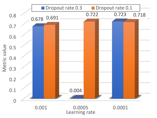
Figure 10.
Metric values for ADAM optimiser.
3.1.2. Impact of the Learning Rate on Multiphase Interturn Short-Circuit Classification
During the training of artificial neural networks with the use of function gradient descent methods, one of the hyperparameters used is the learning rate. The learning rate parameter determines the impact of updating the weights in successive learning steps. A too-high value of the learning rate may result in faster convergence, but the algorithm may miss the minimum of the loss function during the training process, while a properly selected learning rate may lead to a more accurate result (finding a point closer to the minimum of the loss function), but this may translate into a longer training time for the network. The default learning rate for gradient methods was 0.001. In the tests carried out, the influence of the learning rate on the inference results regarding the state of machine failure was examined. For this purpose, the learning rate was reduced twice and by an order of magnitude. The concept of the influence of the learning factor on the learning process is presented in Figure 11a,b.
As can be seen in Figure 11a, too high a value of the learning rate may lead to a situation in which the algorithm will not be able to find the global minimum of the function due to too-large step updates. However, in Figure 11b it can be seen that a smaller step value may lead to finding the global minimum but will require a larger number of iterations. The loss function presented in Figure 11 is only intended to present the idea of selecting the learning rate. Of course, in the case of neural networks, loss functions are often functions with a very large number of dimensions, which makes it impossible to present them graphically. It should also be mentioned that some loss function optimisation algorithms have the ability to adaptively select the learning rate in each iteration, which helps to converge to the global minimum, as shown in Figure 11a,b. In Figure 11, an example shape of the cost function is shown in blue, while the subsequent steps of the learning algorithm are marked in green.
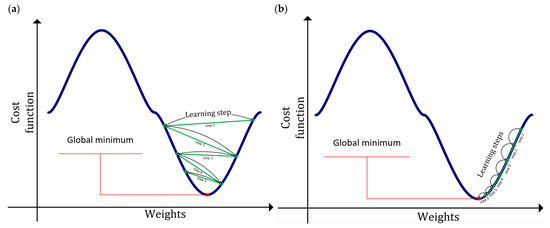
Figure 11.
Learning rate impact: (a) learning rate too high and (b) correct learning rate.
The influence of the learning rate on the inference results is shown in Figure 12, Figure 13 and Figure 14.
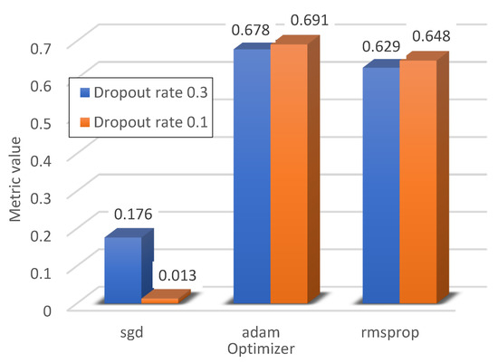
Figure 12.
The metric values for the learning rate are equal to 0.001.
Figure 12 shows the metric value for a learning rate of 0.001. As can be seen in the case of such a value of the learning coefficient, the best results in the classification of inter-turn short circuits of the induction machine were obtained using the ADAM optimiser. The results for the SGD optimiser clearly differ not only from the ADAM optimiser, but also from RMSProp.
Reducing the learning factor to 0.005 significantly improved the quality of interturn fault classification using all three optimisers. The biggest improvement is seen with the SGD optimiser. The possible cause of the classification problem for the ADAM optimiser and the dropout value of 0.3 has already been mentioned earlier.
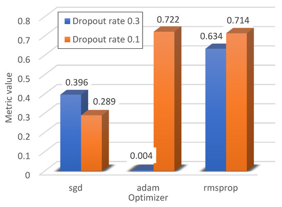
Figure 13.
Metric values for the learning rate equal to 0.005.
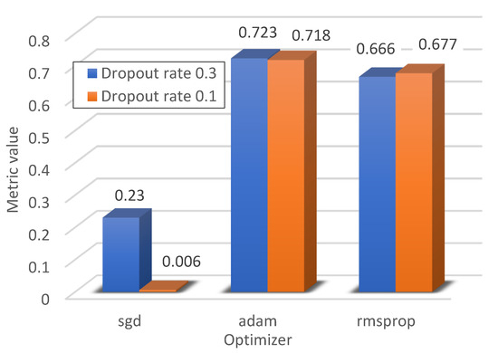
Figure 14.
The metric values for the learning rate equal to 0.0001.
Further reducing the learning rate allowed us to achieve the highest result for the metric in the case of the ADAM optimiser out of all three learning rate values considered.
3.1.3. Impact of Dropout Rate on Multiphase Interturn Short-Circuit Classification
The dropout rate informs about the number of neurones that will randomly ‘extinguish’ in each epoch during the learning process. The impact of the dropout rate on the learning process is shown in Figure 15 and Figure 16.
Figure 15 and Figure 16 show the impact of the dropout on the quality of the optimiser. The article considered two values of the dropout coefficient: 0.3, meaning that 30% of neurones were dropped at each iteration, and 0.1, meaning that 10% of neurones were dropped. As can be seen, with the exception of the ADAM optimiser with a learning rate of 0.0005, the greatest impact of dropout can be seen in the case of the SGD algorithm. Again, increasing dropout clearly improved the classification results. In the case of the RMSProp and ADAM optimisers for the developed neural network, the impact of dropout is not significant; however, the best classification results were obtained for the ADAM optimiser with a dropout value of 0.3.

Figure 15.
Metric values for the dropout rate equal to 0.3.
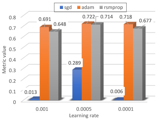
Figure 16.
The metric values for the dropout rate equal to 0.1.
3.2. Tuned CNN—Stage II
The next stage of the research was to tune such model parameters as the number of kernels in the convolutional layers and the number of kernels in the dense layer. The tuned parameters and the range of their variability in the second stage are presented in Table 6.

Table 6.
Hyperparameter values during second turn.
The results of optimisation in the second stage of network learning are shown in Figure 17, Figure 18 and Figure 19 and Table 7.
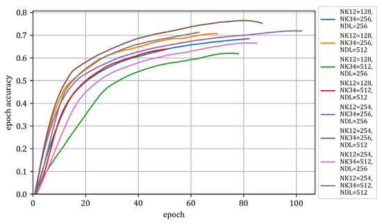
Figure 17.
Value of the metric as a function of epoch (Stage II).
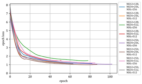
Figure 18.
The value of the loss function in the epoch function (Stage II).
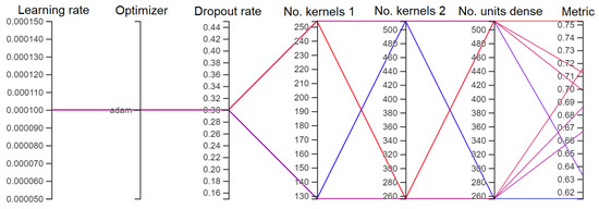
Figure 19.
Hyperparameter tuning configurations (Stage II).

Table 7.
Hyperparameter tuning results in Stage II.
Figure 17, Figure 18 and Figure 19 show the results of the network training process. Figure 17 shows how the metric value changed in subsequent epochs while training the model. Figure 18 shows the decline in the loss function as a function of epochs, while Figure 19 graphically presents the considered configurations of the network hyperparameters used during the second stage of network tuning.
3.2.1. Impact of Number of Kernels on Multiphase Interturn Short-Circuit Classification
Choosing the right number of kernels in convolutional layers can have a crucial impact on the quality of short-circuit classification. Too few kernels may be insufficient to detect specific features of the current signal during short circuits for a small number of shorted turns, while too many kernels may lead to overfitting of the model. Therefore, the appropriate choice of the number of kernels can significantly affect the results. The choice of the number of kernels depends on the problem under consideration. In general, it requires extensive experience of the diagnostician, but in order to eliminate the influence of the human factor, the article proposes the selection of the number of kernels for the problem of interturn short circuits using the grid search method.
The results grouped by layers are presented in Figure 19, Figure 20, Figure 21, Figure 22, Figure 23 and Figure 24.
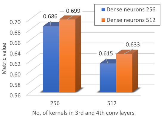
Figure 20.
Metric value for 128 kernels in the 1st and 2nd conv layers.
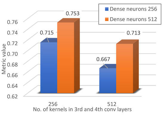
Figure 21.
Metric value for 254 kernels in the 1st and the 2nd conv layers.
During the research, the influence of the network structure on the recognition of stator failures was also checked. Figure 20 and Figure 21 show the influence of the number of neurones in the first and second convolutional layers. It can be noticed that increasing the number of neurones in the case of classifying a large number of interturn short circuit configurations has a positive effect on the classification result.
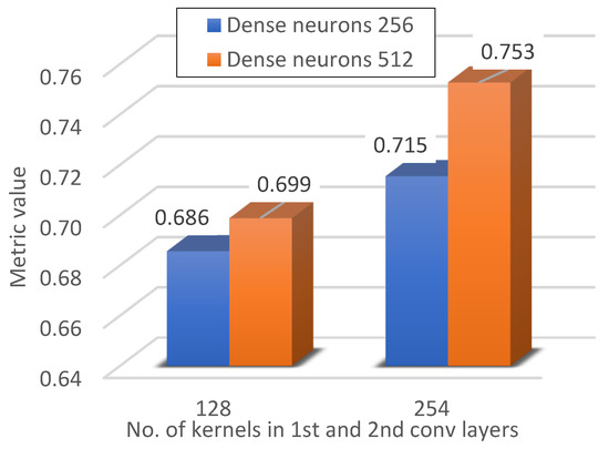
Figure 22.
Metric value for 256 kernels in the 3rd and 4th conv layers.

Figure 23.
Metric value for 512 kernels in the 3rd and 4th conv layers.
Then, the influence of the number of neurones in the deeper layers of the network on the quality of failure classification was checked. As can be seen in Figure 21 and Figure 22, in this case, unlike increasing the number of neurones in the first and second layers, the quality of the classifier deteriorates. One of the reasons may be overfitting, i.e., overfitting the model to detect short circuits in the training set, which may negatively affect generalisation. Too many neurones may result in model overfitting.
3.2.2. Impact of Number of Neurones in Dense Layer on Multiphase Interturn Short-Circuit Classification
The impact of changing the number of neurones in the dense layer on the network results is shown in Figure 24 and Figure 25.
The concept of network operation and the selected results are presented in Figure 26 and Figure 27, respectively. The confusion matrix represents the number of correct network responses in relation to the expected value. The vertical axis shows the expected values, while the horizontal axis shows the values predicted by the network. The description of the axis in Figure 27 refers to the number of shorted turns in the individual phases of the machines. The value on the left corresponds to phase A, the middle value corresponds to phase B, and the right value corresponds to phase C. The values specifying the number of shorted turns in the phase are separated by a space character. Due to limitations in the size of the figure, only a sample slice of the confusion matrix is shown.
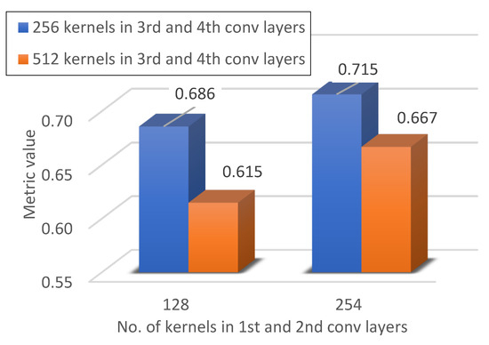
Figure 24.
Metric value for 256 neurones in the dense layer.
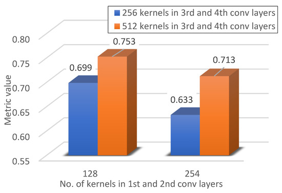
Figure 25.
Metric value for 512 neurones in the dense layer.
The change in the number of neurones in the case of convolutional layers concerned the part of the model that was used to extract detailed features from the training set. During the research, in addition to the influence of changes in the number of neurones in the part of the model related to feature extraction, the influence of the number of neurones in the part of the model responsible for classification, that is, in the dense layer, was also examined. As can be seen in Figure 24 and Figure 25, in the general case, increasing the number of neurones in the classification part of the developed network improved the quality of failure detection. Only in the case of 254 neurones in the convolutional layers and 512 neurones in the dense layer is a deterioration in the quality of classification visible.

Figure 26.
The concept of neural network operation.
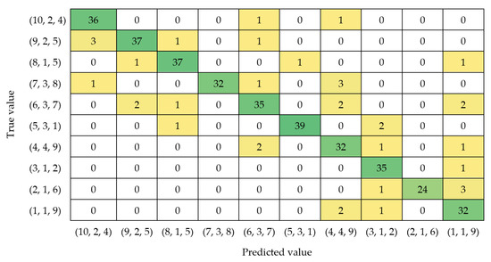
Figure 27.
Example of a neural network result.
Due to the size of the confusion matrix, Figure 27 shows only randomly selected results for randomly selected classes. The number of examples classified correctly is marked in green, while the examples classified incorrectly are marked in yellow.
4. Conclusions
The paper presents stator winding diagnostics of an induction machine with a multiphase interturn short circuits failure. During the diagnostic process, a deep neural network was successfully used. The use of advanced structures of deep neural networks in the diagnostics of electric motors allows for diagnostics based on more complex learning patterns. In addition, the paper presents the method and the influence of selected network hyperparameter tuning on the learning results. Research has shown that in the case of using deep neural networks in the diagnosis of the three-phase squirrel-cage induction machine stator winding, hyperparameter tuning based on the grid search method can be used successfully. Furthermore, trends in the tuning of network parameters were indicated during the generalisation of the fault classification process in induction machines. It can be seen in the case of stator winding diagnostics in the form of multiphase interturn short circuits with selected parameters: the worst results were obtained by using the SGD optimiser. The best results were obtained using the ADAM optimiser, with a small value of the learning coefficient, which may affect the speed at which the algorithm achieves convergence, but allows for better results during failure classification. In the further part of the investigation, the influence of the number of kernels in the convolutional layers and units in the dense layer on the results of the stator winding failure classifier was demonstrated. As can be seen, increasing the number of kernels to 254 and 256 in the respective convolutional layers, as well as increasing the number of neurones in the dense layer to 512 improved the classification quality. However, too many kernels and units in the dense layer, due to too-fast adjustment of the network to the training data, may shorten the time required to achieve convergence, but may have a negative impact on inferring the degree of failure of the machine.
Author Contributions
Conceptualization, W.P. and K.G.; methodology, K.G.; software, K.G.; validation, W.P. and K.G.; formal analysis, K.G.; investigation, W.P. and K.G.; resources, W.P. and K.G.; data curation, W.P and K.G.; writing—original draft preparation, K.G.; writing—review and editing, W.P.; visualization, K.G.; supervision, W.P.; project administration, W.P.; funding acquisition, W.P. All authors have read and agreed to the published version of the manuscript.
Funding
This research was funded by a project of the Poznań University of Technology SBAD: 0212/SBAD/0592.
Data Availability Statement
The datasets presented in this article are not readily available because the data are part of an ongoing study.
Conflicts of Interest
The authors declare no conflict of interest.
References
- Biswal, A.P.; Satpathy, S. Vector Control of 3-Phase Induction Motor. In Proceedings of the 2021 1st Odisha International Conference on Electrical Power Engineering, Communication and Computing Technology (ODICON), Bhubaneswar, India, 8–9 January 2021; pp. 1–4. [Google Scholar] [CrossRef]
- Gecer, B.; Tosun, O.; Apaydin, H.; Oyman Serteller, N.F. Comparative Analysis of SRM, BLDC and Induction Motor Using ANSYS/Maxwell. In Proceedings of the 2021 International Conference on Electrical, Computer, Communications and Mechatronics Engineering (ICECCME), Mauritius, Mauritius, 7–8 October 2021; pp. 1–6. [Google Scholar] [CrossRef]
- Gumilar, L.; Nugroho, W.S.; Sholeh, M. Power Quality of Synchronous Generator under Conditions of Starting Large Induction Motors Simultaneously and Sequentially. In Proceedings of the 2021 7th International Conference on Electrical, Electronics and Information Engineering (ICEEIE), Malang, Indonesia, 2 October 2021; pp. 66–71. [Google Scholar] [CrossRef]
- Chinthala, A.; Vuddanti, S. Performance Analysis of Induction Motor and PMSM for Electrical Vehicle Traction Application. In Proceedings of the 2022 IEEE International Conference on Distributed Computing and Electrical Circuits and Electronics (ICDCECE), Ballari, India, 23–24 April 2022; pp. 1–6. [Google Scholar] [CrossRef]
- Hooli, S.S.; Vadde, A.; Manickavasagam, K.; Kadambi, G.R. Fuzzy Based Health Monitoring of Electric Vehicle Motor using Time Domain Analysis. In Proceedings of the 2021 International Conference on Sustainable Energy and Future Electric Transportation (SEFET), Hyderabad, India, 21–23 January 2021; pp. 1–6. [Google Scholar] [CrossRef]
- Kerdsup, B.; Masomtob, M. Comparative Design between Induction Motor and Synchronous Reluctance Motor used for Electric Vehicle Conversion. In Proceedings of the 2022 25th International Conference on Electrical Machines and Systems (ICEMS), Chiang Mai, Thailand, 29 November–2 December 2022; pp. 1–4. [Google Scholar] [CrossRef]
- Priyanka, C.P.; Nair, N.S.; Jagdanand, G. Thermal Analysis of Multiphase Induction Motor for Electric Vehicle Applications. In Proceedings of the 2022 IEEE Transportation Electrification Conference & Expo (ITEC), Anaheim, CA, USA, 15–17 June 2022; pp. 801–806. [Google Scholar] [CrossRef]
- Takahashi, A.; Sugimoto, S.; Nishihama, K.; Sumita, S.; Taniguchi, S.; Hoshino, K.; Maekawa, N. Mechanical Winding Changeover System of Induction Motors for Vehicle Applications. In Proceedings of the 2022 International Conference on Electrical Machines (ICEM), Valencia, Spain, 5–8 September 2022; pp. 367–372. [Google Scholar] [CrossRef]
- Afanasyev, Y.; Pashali, D.; Yushkova, O.; Zhuravlev, D. Investigation of the Rotor Slots Skew Effect on the Induction Motor Characteristics. In Proceedings of the 2021 International Conference on Electrotechnical Complexes and Systems (ICOECS), Ufa, Russia, 16–18 November 2021; pp. 214–218. [Google Scholar] [CrossRef]
- Ferdiansyah, I.; Purwanto, E.; Prabowo, G.; Adila, A.F.; Rusli, M.R.; Irawan, R. Interfacing PCI 1710 and Real-Time Windows Target for Induction Motor Speed Control Based on Vector Control Designed by Variable Flux Reference. In Proceedings of the 2022 International Conference on Electrical Engineering, Computer and Information Technology (ICEECIT), Jember, Indonesia, 22–23 November 2022; pp. 113–117. [Google Scholar] [CrossRef]
- Barański, M. Electrothermal analysis of start-up process in the squirrel cage induction motor using FEM. Czas. Tech. Elektrotechnika 2016, 2-E, 151–160. [Google Scholar] [CrossRef]
- Ma, Z.; Zhou, C.; Hepburn, D.M.; Cowan, K. FEM simulation of electrical stresses within motor stator windings for online PD Localization. In Proceedings of the 2015 IEEE 11th International Conference on the Properties and Applications of Dielectric Materials (ICPADM), Sydney, Australia, 19–22 July 2015; pp. 668–671. [Google Scholar] [CrossRef]
- Pečínka, P.; Kocman, S.; Pečínková, V. Use of FEM modeling to optimize the design of induction motor. In Proceedings of the 2022 ELEKTRO (ELEKTRO), Krakow, Poland, 23–26 May 2022; pp. 1–6. [Google Scholar] [CrossRef]
- Tvoric, S.; Tomicic, B.; Car, S. Calculation of Asynchronous Traction Motor Start-Up Characteristics by FEM Method. In Proceedings of the International Symposium on Power Electronics Power Electronics, Electrical Drives, Automation and Motion, Sorrento, Italy, 20–22 June 2012. [Google Scholar]
- Ansari, M.N.; Singh, A.K.; Kumar, P. Performance analysis of a hybrid dual rotor motor for electric vehicle application. In Proceedings of the 2012 XXth International Conference on Electrical Machines, Marseille, France, 2–5 September 2012; pp. 2002–2007. [Google Scholar] [CrossRef]
- Bekir, W.; Messal, O.; Benabou, A. Permanent Magnet Non-Linear Demagnetization Model for FEM Simulation Environment. IEEE Trans. Magn. 2022, 58, 7400405. [Google Scholar] [CrossRef]
- Mujaahid, F.; Mustar, M.Y. Iron Losses Quick Prediction of Permanent Magnet Synchronous Motor Based on FEM Analysis. In Proceedings of the 2022 2nd International Conference on Electronic and Electrical Engineering and Intelligent System (ICE3IS), Yogyakarta, Indonesia, 4–5 November 2022; pp. 94–98. [Google Scholar] [CrossRef]
- Pal, S.; Sengupta, M. FEM analysis and experiments of a Double-sided Axial Flux Switched Reluctance Motor for two alternative phase winding terminal connections. In Proceedings of the 2022 IEEE International Conference on Signal Processing, Informatics, Communication and Energy Systems (SPICES), Thiruvananthapuram, India, 10–12 March 2022; Volume 1, pp. 418–424. [Google Scholar] [CrossRef]
- Trifa, V.; Marginean, C.; Trifa, O. FEM analysis of reluctant motors for direct driving of the light electric vehicles. In Proceedings of the 2008 18th International Conference on Electrical Machines, Vilamoura, Portugal, 6–9 September 2008; pp. 1–4. [Google Scholar] [CrossRef]
- Das, S.; Roy, D.; Sengupta, M. Detailed FEM-based Analysis of Vibration in a 3-phase Switched Reluctance Motor and its Experimental Validation. In Proceedings of the 2022 IEEE International Conference on Signal Processing, Informatics, Communication and Energy Systems (SPICES), Thiruvananthapuram, India, 10–12 March 2022. [Google Scholar]
- Bessous, N.; Zouzou, S.E.; Sbaa, S.; Khelil, A. New vision about the overlap frequencies in the MCSA-FFT technique to diagnose the eccentricity fault in the induction motors. In Proceedings of the 2017 5th International Conference on Electrical Engineering-Boumerdes (ICEE-B), Boumerdes, Algeria, 29–31 October 2017; pp. 1–6. [Google Scholar] [CrossRef]
- Deeb, M.; Kotelenets, N.F.; Assaf, T.; Sultan, H.M.; Al-Akayshee, A.S. Three-Phase Induction Motor Short Circuits Fault Diagnosis using MCSA and NSC. In Proceedings of the 2021 3rd International Youth Conference on Radio Electronics, Electrical and Power Engineering (REEPE), Moscow, Russia, 11–13 March 2021; pp. 1–6. [Google Scholar] [CrossRef]
- Eldeeb, H.H.; Secrest, C.; Zhao, H.; Mohammed, O.A. Time-Domain based Diagnosis of Stator Incipient Faults in DTC Driven Induction Motors using External Electro Magnetic Signatures. In Proceedings of the 2021 IEEE Energy Conversion Congress and Exposition (ECCE), Vancouver, BC, Canada, 10–14 October 2021; pp. 5124–5128. [Google Scholar] [CrossRef]
- Górny, K.; Kuwałek, P.; Pietrowski, W. Increasing Electric Vehicles Reliability by Non-Invasive Diagnosis of Motor Winding Faults. Energies 2021, 14, 2510. [Google Scholar] [CrossRef]
- Bessous, N.; Sbaa, S.; Toumi, A. Experimental investigation on broken rotor bar faults in three phase induction motors using MVSA-FFT method. In Proceedings of the 2018 6th International Conference on Control Engineering & Information Technology (CEIT), Istanbul, Turkey, 25–27 October 2018; pp. 1–7. [Google Scholar] [CrossRef]
- Kabul, A.; Ünsal, A. An Alternative Approach for the Detection of Broken Rotor Bars and Bearing Faults of Induction Motor Based on Vibration Signals. In Proceedings of the 2021 8th International Conference on Electrical and Electronics Engineering (ICEEE), Antalya, Turkey, 9–11 April 2021; pp. 126–131. [Google Scholar] [CrossRef]
- Sun, W.; Cao, X. Curvature enhanced bearing fault diagnosis method using 2D vibration signal. J. Mech. Sci. Technol. 2020, 34, 2257–2266. [Google Scholar] [CrossRef]
- Husari, F.; Seshadrinath, J. Inter-Turn Fault Diagnosis of Induction Motor Fed by PCC-VSI Using Park Vector Approach. In Proceedings of the 2020 IEEE International Conference on Power Electronics, Drives and Energy Systems (PEDES), Jaipur, India, 16–19 December 2020; pp. 1–6. [Google Scholar] [CrossRef]
- Mahesh, A.; Aadhavan, B.A.; Meenaa, V.V.; Omar, M.B.; Ibrahim, R.B.; Salehuddin, N.F.; Sujatha, R. Employment of ANN for Predictive Motor Maintenance and Bearing Fault Detection Using Park’s Vector Analysis. In Proceedings of the 2022 IEEE 5th International Symposium in Robotics and Manufacturing Automation (ROMA), Malacca, Malaysia, 6–8 August 2022; pp. 1–6. [Google Scholar] [CrossRef]
- Sharma, A.; Chatterji, S.; Mathew, L. A Novel Park’s Vector Approach for Investigation of Incipient Stator Fault Using MCSA in Three-Phase Induction Motors. In Proceedings of the 2017 International Conference on Innovations in Control, Communication and Information Systems (ICICCI), Greater Noida, India, 12–13 August 2017; pp. 1–5. [Google Scholar] [CrossRef]
- Basaran, M.; Fidan, M. Induction motor fault classification via entropy and column correlation features of 2D represented vibration data. Eksploat. Niezawodn. 2021, 23, 132–142. [Google Scholar] [CrossRef]
- Zimnickas, T.; Vanagas, J.; Dambrauskas, K.; Kalvaitis, A. A Technique for Frequency Converter-Fed Asynchronous Motor Vibration Monitoring and Fault Classification, Applying Continuous Wavelet Transform and Convolutional Neural Networks. Energies 2020, 13, 3690. [Google Scholar] [CrossRef]
- Choi, D.-J.; Han, J.-H.; Park, S.-U.; Hong, S.-K. Comparative Study of CNN and RNN for Motor fault Diagnosis Using Deep Learning. In Proceedings of the 2020 IEEE 7th International Conference on Industrial Engineering and Applications (ICIEA), Bangkok, Thailand, 16–21 April 2020; pp. 693–696. [Google Scholar] [CrossRef]
- Han, J.-H.; Choi, D.-J.; Park, S.-U.; Hong, S.-K. Diagnosis of motor aging through CNN model using signal correlation. In Proceedings of the 2020 20th International Conference on Control, Automation and Systems (ICCAS), Busan, Republic of Korea, 13–16 October 2020; pp. 571–575. [Google Scholar] [CrossRef]
- Mukhopadhyay, R.; Panigrahy, P.S.; Misra, G.; Chattopadhyay, P. Quasi 1D CNN-based Fault Diagnosis of Induction Motor Drives. In Proceedings of the 2018 5th International Conference on Electric Power and Energy Conversion Systems (EPECS), Kitakyushu, Japan, 23–25 April 2018; pp. 1–5. [Google Scholar] [CrossRef]
- Khan, S.A.; Prosvirin, A.E.; Kim, J.-M. Towards bearing health prognosis using generative adversarial networks: Modeling bearing degradation. In Proceedings of the 2018 International Conference on Advancements in Computational Sciences (ICACS), Lahore, Pakistan, 19–21 February 2018; pp. 1–6. [Google Scholar] [CrossRef]
- Lee, Y.O.; Jo, J.; Hwang, J. Application of deep neural network and generative adversarial network to industrial maintenance: A case study of induction motor fault detection. In Proceedings of the 2017 IEEE International Conference on Big Data (Big Data), Boston, MA, USA, 11–14 December 2017; pp. 3248–3253. [Google Scholar] [CrossRef]
- Shim, J.; Joung, T.; Lee, S.; Ha, J.-I. Audio Data-driven Anomaly Detection for Induction Motor Based on Generative Adversarial Networks. In Proceedings of the 2022 IEEE Energy Conversion Congress and Exposition (ECCE), Detroit, MI, USA, 9–13 October 2022; pp. 1–5. [Google Scholar] [CrossRef]
- Khan, T.; Alekhya, P.; Seshadrinath, J. Incipient Inter-turn Fault Diagnosis in Induction motors using CNN and LSTM based Methods. In Proceedings of the 2018 IEEE Industry Applications Society Annual Meeting (IAS), Portland, OR, USA, 23–27 September 2018; pp. 1–6. [Google Scholar] [CrossRef]
- Rayhan, F.; Shaurov, S.; Nashrah Khan, A.; Jahan, S.; Zaman, R.; Hasan, Z.; Rahman, T.; Bhuiyan, E.A. A Bi-directional Temporal Sequence Approach for Condition Monitoring of Broken Rotor Bar in Three-Phase Induction Motors. In Proceedings of the 2023 International Conference on Electrical, Computer and Communication Engineering (ECCE), Chittagong, Bangladesh, 23–25 February 2023; pp. 1–6. [Google Scholar] [CrossRef]
- Xiao, D.; Huang, Y.; Zhang, X.; Shi, H.; Liu, C.; Li, Y. Fault Diagnosis of Asynchronous Motors Based on LSTM Neural Network. In Proceedings of the 2018 Prognostics and System Health Management Conference (PHM-Chongqing), Chongqing, China, 26–28 October 2018; pp. 540–545. [Google Scholar] [CrossRef]
- Han, J.-H.; Choi, D.-J.; Hong, S.-K.; Kim, H.-S. Motor Fault Diagnosis Using CNN Based Deep Learning Algorithm Considering Motor Rotating Speed. In Proceedings of the 2019 IEEE 6th International Conference on Industrial Engineering and Applications (ICIEA), Tokyo, Japan, 12–15 April 2019; pp. 440–445. [Google Scholar] [CrossRef]
Disclaimer/Publisher’s Note: The statements, opinions and data contained in all publications are solely those of the individual author(s) and contributor(s) and not of MDPI and/or the editor(s). MDPI and/or the editor(s) disclaim responsibility for any injury to people or property resulting from any ideas, methods, instructions or products referred to in the content. |
© 2024 by the authors. Licensee MDPI, Basel, Switzerland. This article is an open access article distributed under the terms and conditions of the Creative Commons Attribution (CC BY) license (https://creativecommons.org/licenses/by/4.0/).