Abstract
In critical applications of electrical machines, ensuring validity and safety is paramount to prevent system failures with potentially hazardous consequences. The integration of machine learning (ML) technologies plays a crucial role in monitoring system performance and averting failures. Among various motor types, permanent magnet synchronous motors (PMSMs) are widely favored for their versatile speed range, enhanced power density, and ease of control, finding applications in both industrial settings and electric vehicles. This study focuses on the detection and classification of the percentage of broken magnets in PMSMs using a pre-trained AlexNet convolutional neural network (CNN) model. The dataset was generated by combining finite element methods (FEMs) and short-time Fourier transform (STFT) applied to stator phase currents, which exhibited significant variations due to diverse broken magnet structures. Leveraging transfer learning, the pre-trained AlexNet model underwent adjustments, including the elimination and rearrangement of the final three layers and the introduction of new layers tailored for electrical machine applications. The resulting pre-trained CNN model achieved a remarkable performance, boasting a 99.94% training accuracy and 0.0004% training loss in the simulation dataset, utilizing a PMSM with 4% magnet damage for experimental validation. The model’s effectiveness was further affirmed by an impressive 99.95% area under the receiver operating characteristic (ROC) curve in the experimental dataset. These results underscore the efficacy and robustness of the proposed pre-trained CNN method in detecting and classifying the percentage of broken magnets, even with a limited dataset.
1. Introduction
Electrical motors play a crucial role in converting electrical energy into mechanical energy. They are widely used in various industries and applications, including manufacturing, transportation, appliances, and many more [1]. Permanent magnet synchronous motors (PMSMs) are popular in industrial applications because of their small size, high efficiency, high torque, and excellent dynamic performance [2]. The actual use of motors can cause them to be exposed to environmental, physical, and thermal stress, which can change their normal structure and functioning, resulting in a breakdown. Any departure from the machine’s expected behavior (under the operating circumstances) is referred to as a fault in a machine. The machine’s thermal properties, acoustic noise and vibrations, magnetic quantities like flux, and electrical quantities like current and voltage can all be signs of a fault. To prevent a defect from spreading further, it must be identified and treated when it is still in its early stages [3]. Previous research has looked into the categorization and modeling of faults in PMSMs [4]. Fault detection and diagnosis based on a motor variable analysis is an important technique for ensuring the reliable operation of PMSMs in various industrial applications. It allows for the early detection of faults, which can help prevent more serious damage and reduce downtime for maintenance and repair. Various elements of the motors are widely utilized to extract fault characteristics through different processing techniques. These fault characteristics are then used to identify the specific type of fault occurring in the motor, enabling maintenance personnel to take appropriate corrective actions [5]. Among them, because it is inexpensive and non-invasive, motor current signature analysis (MCSA) is an extensively utilized approach. The current of a motor in operation is measured and stored in MCSA. The characteristics of the motor are determined by analyzing the recorded signal in the time, frequency, or time-frequency domains. This information is then used to diagnose the motor issues. The use of MCSA has been widely employed to investigate motor faults, including rotor, bearing, eccentricity, misalignment, and stator faults [6,7]. The rotor of PMSMs is a critical element, and any faults in it can significantly impede the operational performance of the PMSMs. There are two common types of rotor faults: eccentricity faults (static eccentricity and dynamic eccentricity) and broken magnet faults [8,9]. Failure detection algorithms for the non-stationary state often incorporate time-frequency analysis methods such as wavelet analysis [10], short-time Fourier transform (STFT) [11], Hilbert–Huang transforms [12], and Wigner–Ville distributions [13]. These techniques allow for a more comprehensive analysis of signals in both the time and frequency domains, enabling the detection of faults in systems exhibiting non-stationary behavior. Fast Fourier transform (FFT) is a widely used method for accurately detecting current harmonics [14,15]. In PMSMs, electrical and magnetic faults can introduce certain harmonics in the motor variable spectrum. These harmonics can be analyzed to detect and diagnose the presence of a fault in the motor. The fault pattern is defined as the specific combination of harmonics that are present in the motor variable spectrum for a particular fault. However, in general, the harmonics that are introduced in the motor variable spectrum due to faults can be expressed as follows [16]:
where k is an integer number, p is the number of pole pairs, and is the fundamental frequency of the supply current [16]. According to (1), it is shown that different faults in PMSMs have the same harmonic behavior, and the diagnosis of these faults is challenging. Therefore, it is crucial to conduct research focused on precise and reliable techniques for diagnosing and classifying broken magnet faults. Deep learning (DL)-based approaches are employed to classify broken rotor bars and detect faults in induction motors (IMs) [17]. Deep-SincNet is capable of extracting fault characteristics from the raw data of bearings and broken rotor bars in IMs [18]. The robustness of the DL methods is extracted with the raw dataset for bearing fault detection. DL algorithms are capable of automatically extracting features from bearing data without any prior knowledge of fault characteristic frequencies or operating conditions, provided they are given a large enough dataset to train on [19]. The study of bearing fault detection using the convolutional neural network (CNN) method is popular and has opened a new horizon in the areas of fault detection research [20]. The combination of signal processing and CNN methods is used for inter-turn short-circuit (ITSC), partial demagnetization, and static eccentricity fault detection [21]. The study successfully diagnosed and classified various faults, including normal faults, winding end-turn short circuit faults, demagnetization faults, and hybrid faults (combining winding end-turn short circuit and demagnetization faults) using a CNN model in PMSM. Additionally, the FFT model was used to analyze the characteristics of the fault types, while the FEM method determined the characteristics of the phase currents. Three-phase current data from experiments were used for training and testing the model, and the results demonstrate the effectiveness of the proposed method in fault diagnosis and classification [22]. In another study, two feature extraction methods were used for fault detection. In the first method, a combination of 1D-CNN and wavelet packet transform was utilized, and after these methods, the supervised learning method was used for the classification of the faults [23]. Through the experiment, the frequency domain analysis of the current data of the PMSM’s healthy state, the end-of-winding ITSC fault, the demagnetization fault, and the hybrid fault was performed. Using 1D-CNN, the faults’ classification and diagnosis were carried out. The results demonstrate that, when both errors were present at the same time, the 1D-CNN was able to detect both. The features are automatically extracted from existing signals using 1D-CNN. The proposed technique has a 99.29% success rate in fault diagnosis [24]. An alternative study presents a resilient method for diagnosing open-circuit faults by employing a wavelet convolutional neural network. This approach utilizes compact sample sets generated from normalized current vector trajectory graphs [25]. In addressing the imperative task of detecting and classifying faults in PMSMs, previous research presents an innovative intelligent approach employing bi-spectrum analysis and a CNN. Experimental validation showcases the impressive classification effectiveness of the CNN model [26].
In the present study, a primary focus was the investigation and application of a novel pre-trained AlexNet CNN for the detection and classification of damaged magnets in PMSMs. Departing from traditional approaches laden with computational complexities or intricate signal processing methods, the proposed method capitalizes on the benefits of deep learning. Through the utilization of STFT graphical images derived from a meticulously curated dataset, an exceptional validation accuracy (99.23%) and training accuracy (99.94%) were achieved in the identification and classification of broken magnets. Furthermore, the study emphasizes the significance of this work in the early detection and prevention of damaged magnets, thereby paving the way for a comprehensive and fully automated system within the realm of electric machine health monitoring. This paper is divided into six sections, each focusing on specific aspects of the research. In Section 2, the impact of broken magnets in PMSMs on the stator phase current is discussed, along with an explanation of how STFT analysis is used to analyze and understand these effects. In Section 3, the research paper provides a detailed description of how the dataset is rearranged using a simulation model and STFT analysis. Section 4 emphasizes the architecture of the new pre-trained Alexnet CNN and highlights the utilization of robust transfer learning techniques for the purpose of detection and classification. Section 5 explains the process of obtaining the experimental dataset and demonstrates how the proposed model was verified and tested using this dataset, and Section 6 concludes the study by summarizing the key findings and main contributions of the research, emphasizing their significance and suggesting potential directions for future research.
2. Fundamentals of PMSMs and STFT Analysis for Evaluating Impact of Broken Magnets on Stator Phase Current
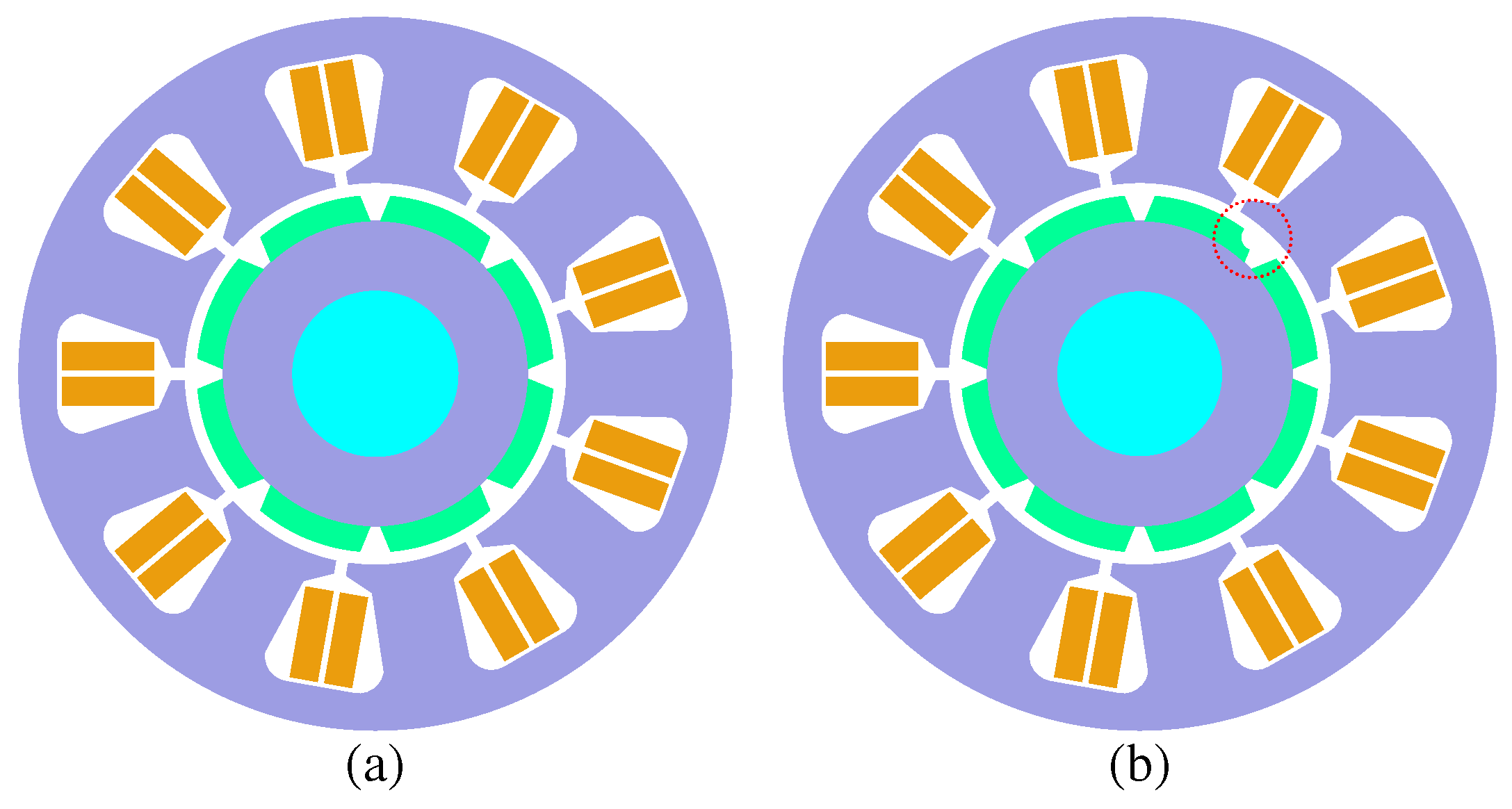
Physically modeling broken magnets in PMSMs involves the removal of sections from the magnets, accurately simulating the presence of cracks or fractures. By physically removing parts of the magnets, the effective magnetic field strength in the motor is reduced. It is important to note that physically modeling broken faults by altering the magnets is a controlled and deliberate process performed for experimental or testing purposes. In real-world scenarios, broken magnets can occur for various reasons, such as mechanical stress or electrical overloading, and they are typically considered undesired and unintentional faults [27]. As a result, the motor may experience reduced output torque, decreased efficiency, increased current harmonics, and increased heating in broken magnet conditions. These effects can negatively impact the motor’s overall performance and reliability [28]. In this study, the broken magnet was fitted on a PMSM. Figure 1a depicts the FEM representation of the intact rotor of the PMSM, whereas Figure 1b illustrates a side view of the rotor with a broken magnet in one pole. In this case, a section corresponding to roughly 3% of a single permanent magnet (PM) area was deliberately removed from the magnets, forming one pole.
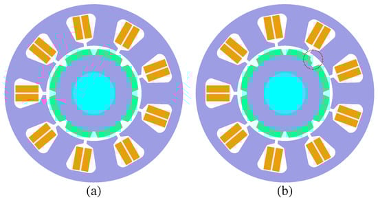
Figure 1.
FEM depiction of (a) healthy four pole pair PMSM rotor and (b) PMSM rotor with the 3% broken magnet of a single PM depicted by the red dotted circle.
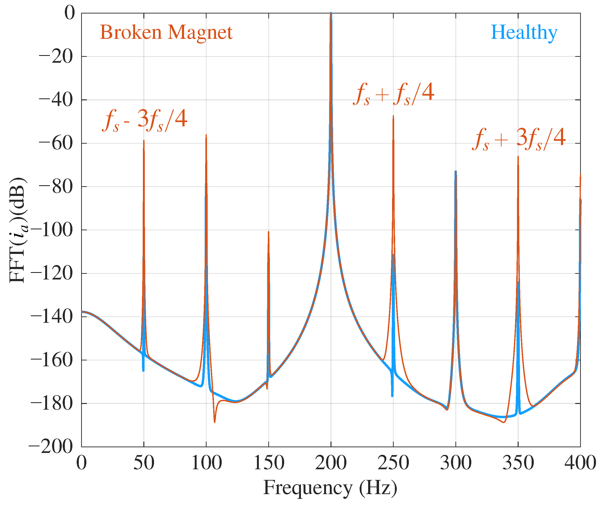
In PMSMs, any form of broken magnet leads to a reduction in the rotor’s magnetic flux. As a result, when a broken magnet occurs, the motor requires a higher current to maintain the same load torque compared to a healthy motor. This is due to the direct relationship between the electromagnetic torque of PMSMs and the cross-product of the current vector and PM flux linkage. Furthermore, a broken magnet introduces periodic disturbances in the PM magnetic field, causing distortions in the induced back EMF. These distortions, in turn, have an impact on the shape and magnitude of the stator phase current waveforms. Upon analyzing the stator phase current waveforms, it becomes apparent that the presence of broken magnets in PMSMs leads to changes in the magnitudes of the stator phase currents and slight distortions in their sinusoidal patterns. These variations occur as a result of additional harmonics introduced into the waveforms. These changes in the waveforms are depicted in the frequency spectra. If the magnets are not distributed evenly throughout the rotor, it can lead to fault signature patterns as described in (1) due to various shapes of broken PMs. The FFT graphs in Figure 2 depict frequency spectra for the comparison of the PMSM phase current in a healthy motor and a motor with broken magnet conditions using the simulation results. The data presented in the graphs illustrate that, in the healthy condition, only the fundamental components appear. However, in the broken magnet condition, the harmonics of the mechanical frequency are depicted without the fundamental components. This demonstrates that the proposed method can accurately predict the behavior of a given broken magnet motor, as the theoretical results are in agreement with the simulation results.
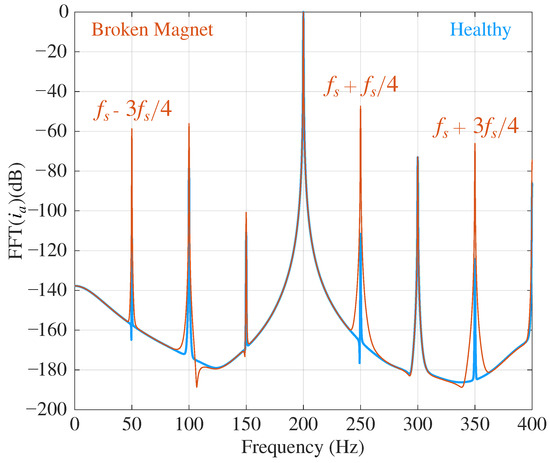
Figure 2.
Comparison of the FFT spectra of the stator current in phase-a for healthy and broken PM.
While Fourier transform is a valuable tool for analyzing signals in the frequency domain by decomposing them into complex exponentials at different frequencies, it does not provide any information about when specific frequencies occur in the time domain [11]. The STFT functions by partitioning a signal into time-domain windows of equal width. The frequency characteristics of each window are subsequently calculated using the FFT. The choice of window size determines the level of time and frequency resolution in the STFT analysis. Smaller windows yield a more precise time resolution but less accurate frequency resolution, whereas larger windows offer an improved frequency resolution at the cost of time resolution [29]. The STFT computes the FFT of a function within a symmetric window function, denoted as . This window function is shifted in time and modulated at a frequency , as expressed by the following equation [30,31]:
The result of performing the STFT analysis is a spectrogram, which displays the distribution of energy among the frequency components of the signal as they change over time. The spectrogram is presented as a three-dimensional plot, showcasing the evolving frequency content of the signal throughout the duration. The formula for calculating the spectrogram is as follows [30,31]:
In real-world applications, signals are commonly sampled at a fixed sampling frequency . Consequently, Equation (2) in the discrete domain can be expressed using the following formula [30,31]:
The equation involves several parameters: N (the number of FFT points), n (the time-domain input sample index), (the input sample), (the window function), H (the window size or width), and k (the frequency index). When performing STFT analysis, it is vital to specify these parameters during the algorithm design. They include the sampling frequency , the number of input samples , the window size , and the choice of window function . Detailed explanations and analyses of these parameters, and their impact on the outcomes of the STFT, can be found in various sources, including references [31,32].
3. Dataset Rearrangement Process Using Finite Element Method and Short Time Fourier Transform Analysis
3.1. FEM Simulation Model
RMxprt allows for the rapid realization of the initial motor design and efficient performance verification, leading to reduced design possibilities for the motor [33]. The software provides users with the capability to generate different motor models by defining various parameters such as the stator and rotor diameter, iron core length, winding details, slot configuration, wire characteristics, insulation, and other relevant factors. Additionally, users can specify the size and material type of the PM [34,35]. Once the necessary parameters are defined, the software employs finite element calculations for both transient and steady-state analysis using Maxwell’s equations. By appropriately setting the boundary conditions and mesh division (as automatic meshing may yield inaccurate results), an ANSYS® Maxwell® 2022 R2 (2D) (ANSYS, Canonsburg, PA, USA) model of the motor is generated. ANSYS® Maxwell® 2022 R2, as a professional design software for rotary motors, offers effective computational capabilities for evaluating performance indicators across different motor types, such as induction motors, synchronous motors, and motors with electronic or mechanical commutation. In this study, the PMSM was designed in ANSYS® Maxwell®. Table 1 presents a concise overview of the key characteristics of the designed motor.

Table 1.
Parameters of the PMSM.
In this paper, a total of thirty-seven (37) simulated PMSMs are examined in nine (9) classes, one of which is in a healthy condition, and the others have various percentages and shapes of broken magnets. Despite the differences in the shape and size of the broken magnet, the same properties were applied to all of the motors in the simulation application. Figure 3a shows a broken magnet within the red circle that is cracked by approximately 3% in one magnet, which is labeled as “B1”, while Figure 3b demonstrates a broken magnet within the red circle that is cracked by approximately 83% in one magnet, which is labeled as “B7”. In this study, the healthy condition is labeled by “H”, and the motors with broken magnets are labeled from “B1” to “B8”.
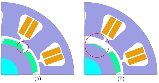
Figure 3.
Broken magnets: (a) approximately 3% damaged; (b) approximately 83% damaged.
The STFT spectrogram of the stator phase current was used to generate a dataset of 4200 images, which was utilized for training and validating a pre-trained Alexnet CNN model. The goal was to create short-term visual representations. Table 2 provides an overview of all the datasets used as input for the training and validation of the model. The dataset was split into two groups, with 80% of the images used for training the model and the remaining 20% used for validation. Initially, the images were sized 700 × 525 × 3, but they were rearranged to suit the CNN model.
Table 2.
Summary of training and validation datasets.
3.2. STFT Spectrogram of Stator Phase Current in Healthy and Broken Magnet PMSM
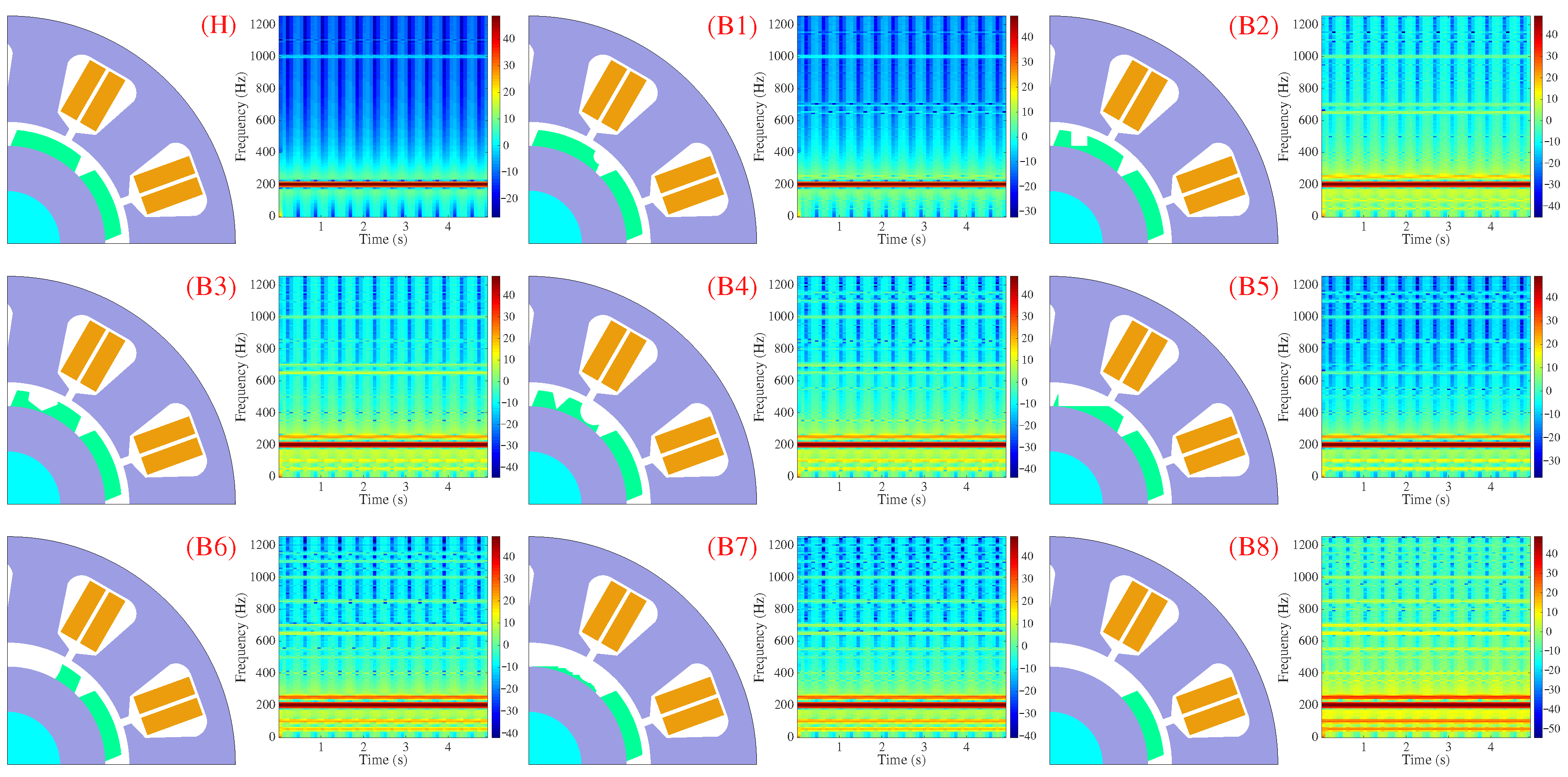
In this study, an STFT analysis of the stator phase current signal was used to detect symptoms of broken magnets in PMSMs. By analyzing the magnitude of specific harmonics, valuable insights could be gained into the condition of the rotor. Figure 4 presents the STFT spectrograms of the stator phase current and FEM model from all the labels. Healthy motors and broken motors with different percentages and shapes of broken magnets were used, both operating under the same conditions.
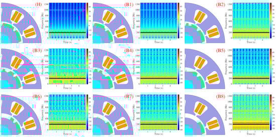
Figure 4.
STFT spectrogram of phase-a currents and 2D FEM models of healthy and PMSM rotors with different shapes and percentages of broken magnets.
4. Motivation for Developing the New Pre-Trained AlexNet CNN Model and Utilization of Robust Transfer Learning Techniques for Detecting and Classifying Broken Magnets
The past few years have seen a great deal of focus on artificial intelligence (AI), especially machine learning (ML) and DL techniques. Numerous researchers have utilized these advanced techniques to explore a new horizon in various fields of technology. DL is a subset of ML that uses algorithms to process data and create models that can learn and make decisions on their own. It differs from other ML techniques in that it uses multiple layers of neurons to process data and create more complex models. For a more precise definition, DL is a form of AI that uses data processing. It is similar to the way a human would learn by taking a pre-learned example and attempting to extract specific features automatically through multiple layers. The mathematical model of the accuracy of a DL model can be calculated as follows [36,37]:
where is a true positive, is a true negative, is a false positive, and is a represented false negative. Precision serves as an indicator of how accurate a model is in correctly identifying positive instances. A high-precision value suggests that the model has a low rate of false positives, making it dependable in its positive predictions. In DL, recall measures the model’s completeness in identifying positive instances and is particularly important when minimizing false negatives is crucial. A high recall value signifies that the model successfully captures a large proportion of positive instances, thereby reducing false negatives. This indicates that the model is reliable in not missing important positive cases. The score is a metric that combines precision and recall by calculating their harmonic mean. It provides a balanced measure that ranges from 0 to 1. The score reaches its maximum value of 1 when both precision and recall are perfect, meaning there are no false positives or false negatives. A higher score indicates the better overall performance of the model in accurately identifying positive instances. Accuracy is a fundamental evaluation metric used in DL to assess the overall performance of a classification model. It measures the proportion of correct predictions made by the model out of the total number of predictions. A higher accuracy value indicates that the model has a greater ability to make correct predictions across all classes. It is commonly employed as a primary metric for evaluating classification models when the dataset is well balanced, with approximately equal instances in each class.
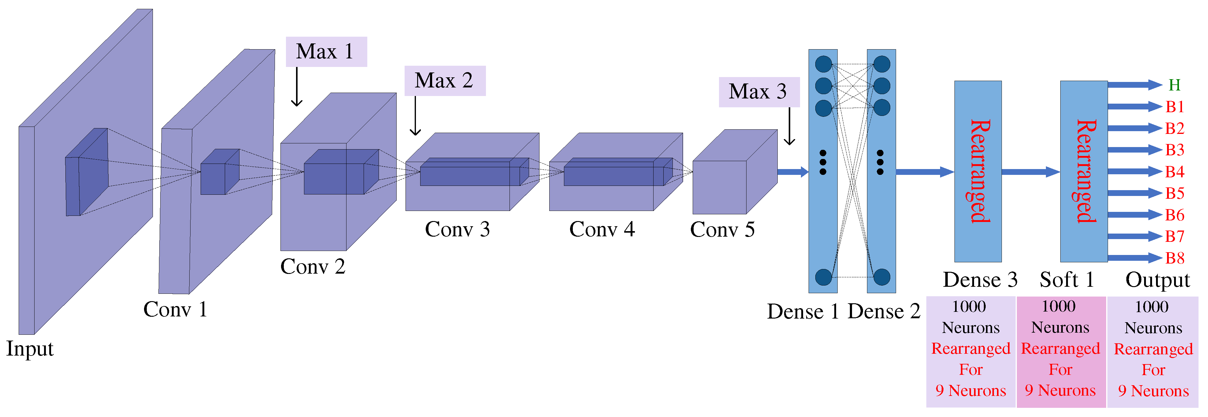
In this paper, nine (9) different classes of healthy and broken magnet PMSMs are investigated. We utilized this technique as an efficient and reliable solution when the available data for training a model from the broken magnet was limited. However, due to the challenges posed by the size and location of the broken magnet, diagnosing the broken one under operational conditions proved to be quite difficult. To capture both global and local information, a larger kernel size is preferred for the convolutional layer to obtain global information, while a smaller kernel size is used to extract local information. The neural network architecture used for broken magnet detection in the PMSM was based on the pre-trained AlexNet model. It consists of 11 layers with a total of 58 million adjustable parameters. Figure 5 depicts the architecture used for broken magnet detection and additional details are provided in Table 3. The new pre-trained AlexNet model consists of three max-pooling layers and five convolutional layers, each followed by a rectified linear unit (ReLU) activation function.
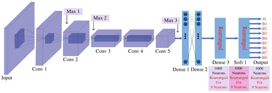
Figure 5.
Architecture of the proposed pre-trained CNN model with transferred learning.
Table 3.
Summary of the proposed pre-trained CNN with transferred learning.
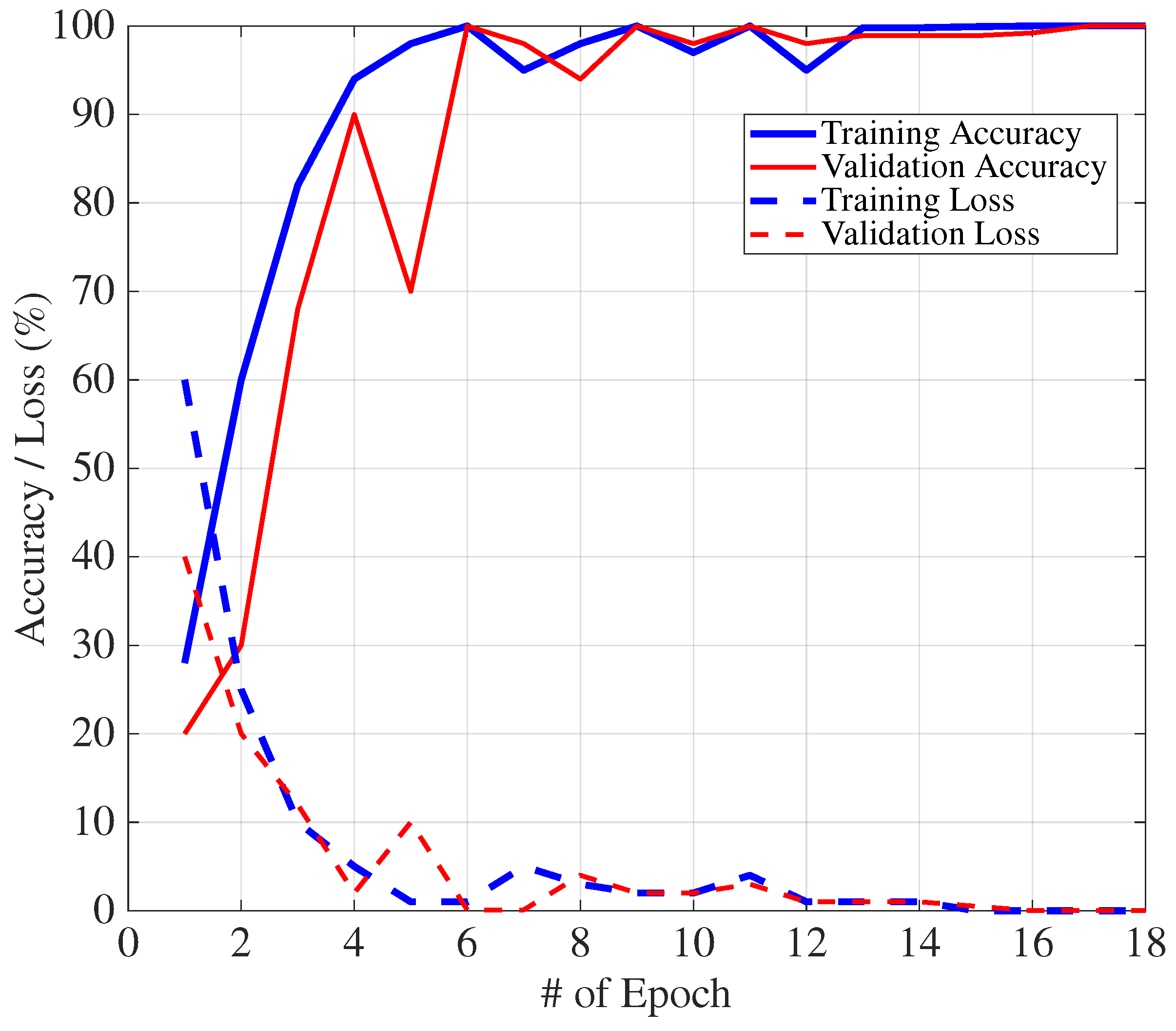
In our new model, to adapt the architecture for broken magnet detection in PMSM, some layers were removed or modified. A “fully connected layer with 9 neurons” was rearranged, and the “softmax function” was used to connect all units to the nine neuronal outputs for broken magnet classification. The learning rate was adjusted to control the rate of network updates. The learning rate of the layers before the last three layers remained unchanged, while this rate in the new layers was increased to facilitate faster learning. This allowed for quick weight updates in these layers. An NVIDIA GeForce 940MX (Santa Clara, CA, USA), 6040 MB GPU laptop was used to run the proposed CNN model. The training process took approximately 11 minutes with a batch size of 75, a maximum of 80 epochs, and a maximum of 520 iterations. The initial learning rate was set to 0.002. The model achieved an impressive validation accuracy of 99.23%, indicating its success in accurately detecting broken magnets. To visualize the training progress, Figure 6 shows a graph depicting the accuracy and loss rates for both training and validation datasets as the number of iterations increases. The accuracy and error graphs demonstrate the effectiveness of the proposed new pre-trained CNN model, including transfer learning techniques for detecting broken magnets.
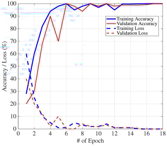
Figure 6.
Training and validation accuracy/loss graphs.
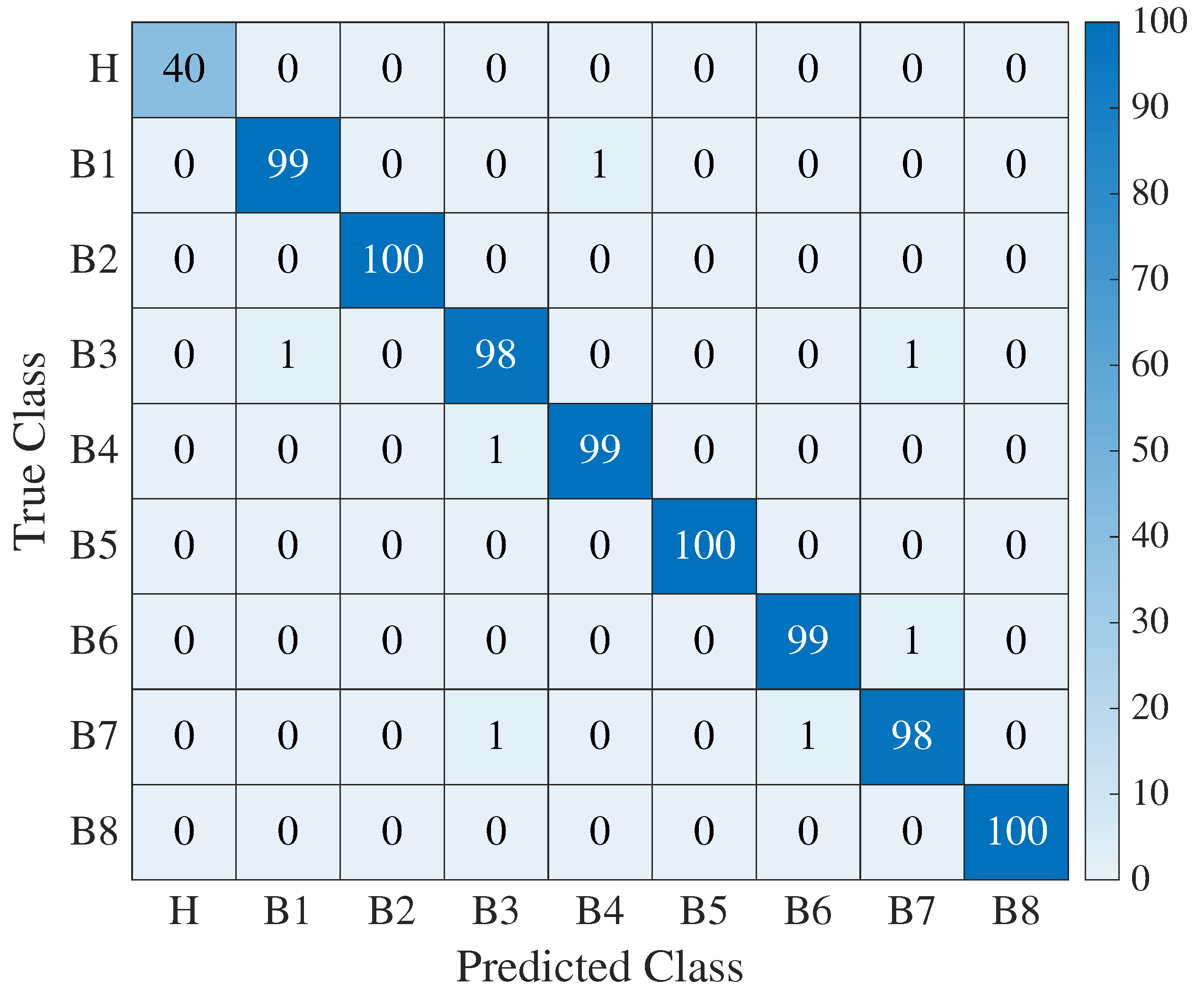
Based on the simulation results, the proposed model achieved an accuracy of 99.94% on the training data with a 0.0004% training loss. This means that the pre-trained Alexnet CNN model with the rearrangement of fully connected layers was able to diagnose broken magnets with high accuracy and use raw data without any additional computational burden, which is a significant advantage of this method. Furthermore, to gain deeper insights into the model’s performance, a confusion matrix was employed to evaluate its classification abilities. The confusion matrix provided a detailed breakdown of the model’s predictions, enabling a comprehensive analysis of its true and false labels identified by the model. Based on the confusion matrix as shown in Figure 7, the proposed model exhibited exceptional performance in accurately classifying broken magnets, as evidenced by the high accuracy rate observed during training and validation. This reinforces the effectiveness of the pre-trained Alexnet CNN model with the rearrangement of fully connected layers for detecting broken magnets with remarkable precision and recall. The utilization of the confusion matrix helped us to assess the model’s ability to accurately detect broken magnets across different classes.
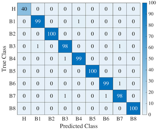
Figure 7.
Confusion matrix for the proposed model’s classification of broken magnets.
5. Discussion and Experimental Case Studies for Model Performance Evaluation
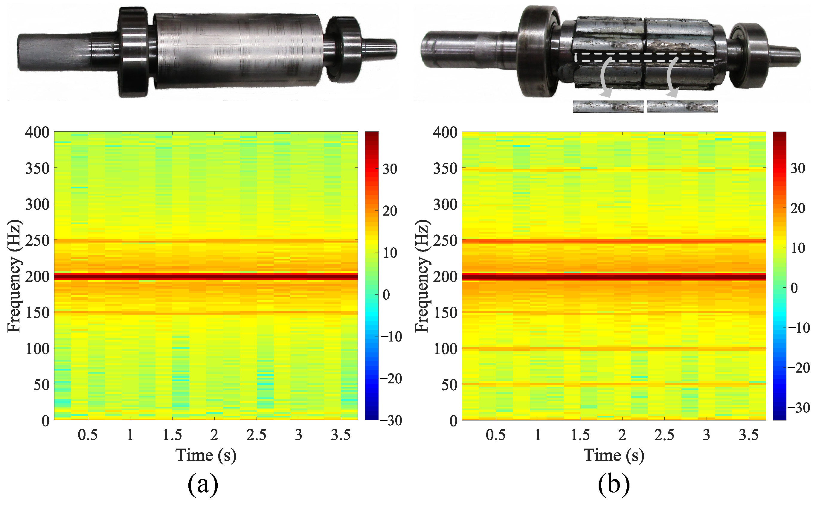
To validate the simulation results, an experimental approach was employed. A vertical cut was made on one of the rotor magnets, as depicted in Figure 8. Subsequently, the motor was tested under identical speed and torque conditions as used in the simulation. The corresponding STFT spectrograms for both the healthy rotor and the rotor with a broken magnet are presented beneath the respective rotor images. In the experimental case study, a broken magnet with approximately 4% damage, which corresponds to the B1 class, was employed. The methodology involved immersing the rotor in a non-conductive oil within a precisely dimensioned measurement container meticulously designed to match the rotor’s shape accurately. Through measurements conducted under both healthy and broken magnet conditions, precise volume data were obtained. The percentage of the broken magnet sections was subsequently determined by analyzing the volume differences between these two states. This non-destructive technique presents distinct advantages for assessing rotor integrity, thereby facilitating data-driven maintenance decisions. In this study, 10% intervals were chosen to categorize fault magnitudes in experimental applications. This decision was driven by the practical considerations of real-world applications, where electrical machines, such as PMSMs, play a pivotal role. It is well established that faults in such systems can have adverse consequences, potentially leading to system failures and the associated risks. Recognizing the critical need for early detection and proactive mitigation of these effects, we adopted the 10% interval categorization to strike a balance between granularity and predictive accuracy. This approach enables us to identify faults before they escalate to levels that may jeopardize system integrity, ensuring the reliability and safety of critical applications. Additionally, the 10% intervals provide a practical framework that aligns with industry practices, allowing our methodology to be readily applied in the field for predictive maintenance and risk mitigation. Moreover, this choice enhances the statistical significance of our findings by ensuring that each fault magnitude category is sufficiently populated, enabling robust analysis and meaningful results.
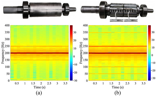
Figure 8.
Experimental PMSM rotor with corresponding STFT spectrograms under simulated conditions: (a) healthy rotor; (b) rotor with a 4% broken magnet.
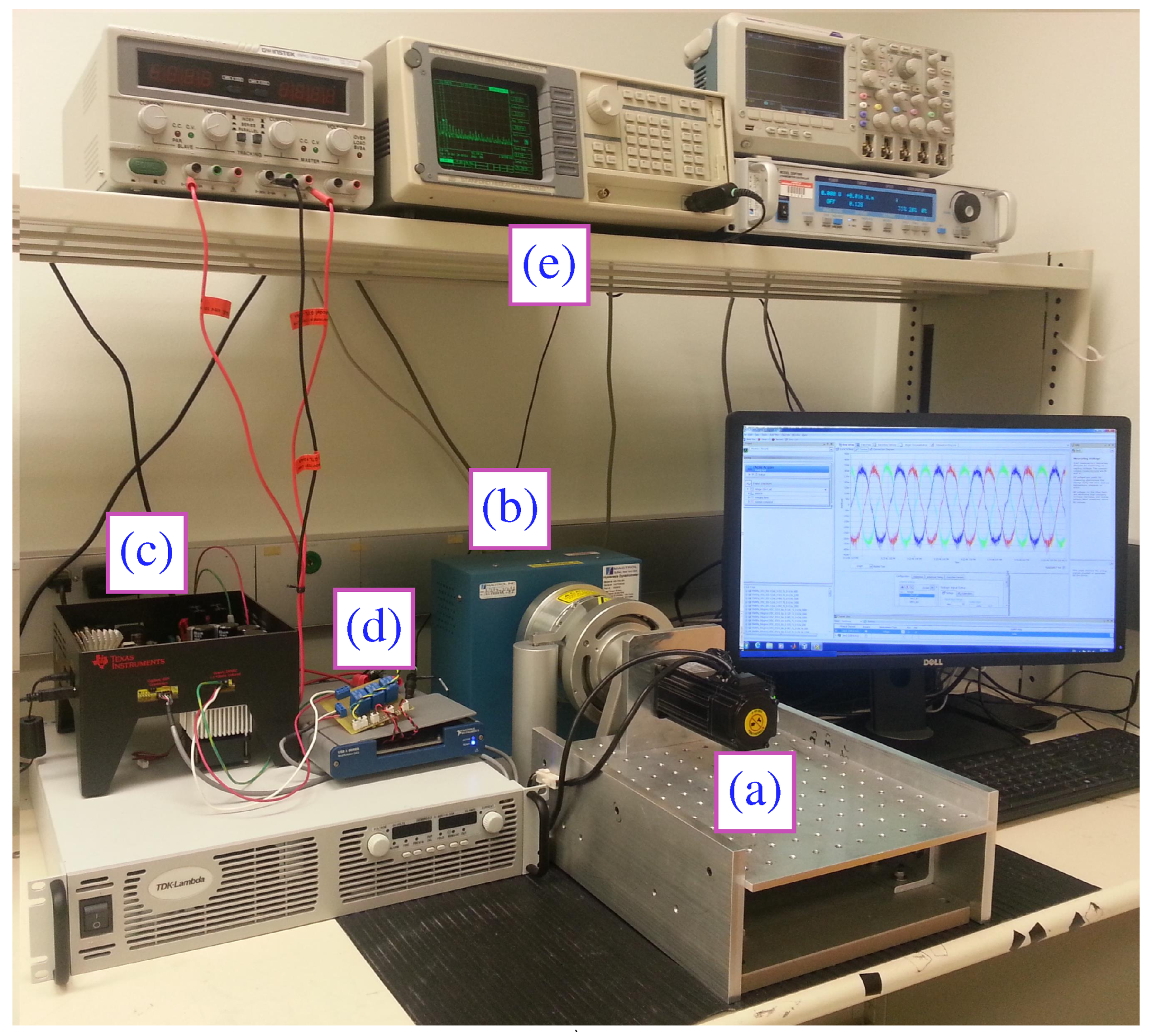
To facilitate this experimentation, a setup was prepared, as depicted in Figure 9. The setup consisted of a PMSM, with its specifications detailed in Table 1. The experimental setup featured a 0.4 kW star-connected PMSM under closed-loop vector control, coupled with a hysteresis dynamometer for precise load adjustment. A flexible coupling was employed to minimize mechanical disturbances, and a 32-bit floating-point TMS320F28335 TI-DSP controller was used for precise motor control. Real-time monitoring of fault signatures was accomplished through a 16-bit dual-core spectrum analyzer. The phase current measurement was facilitated by Hall-effect sensors, with data acquisition performed at a high sampling rate of 50 kSamples/second. It is crucial to underscore that the identical experimental conditions and variables, as described above, were meticulously replicated in the simulation procedure. This rigorous alignment between the experimental and simulation methodologies not only bolsters the validity of the results but also ensures a foundation for seamless replication and further research endeavors.

Figure 9.
Experimental setup of the broken magnet PMSM drive: (a) PMSM; (b) dynamometer; (c) motor drive; (d) data acquisition card; (e) spectrum analyzer.
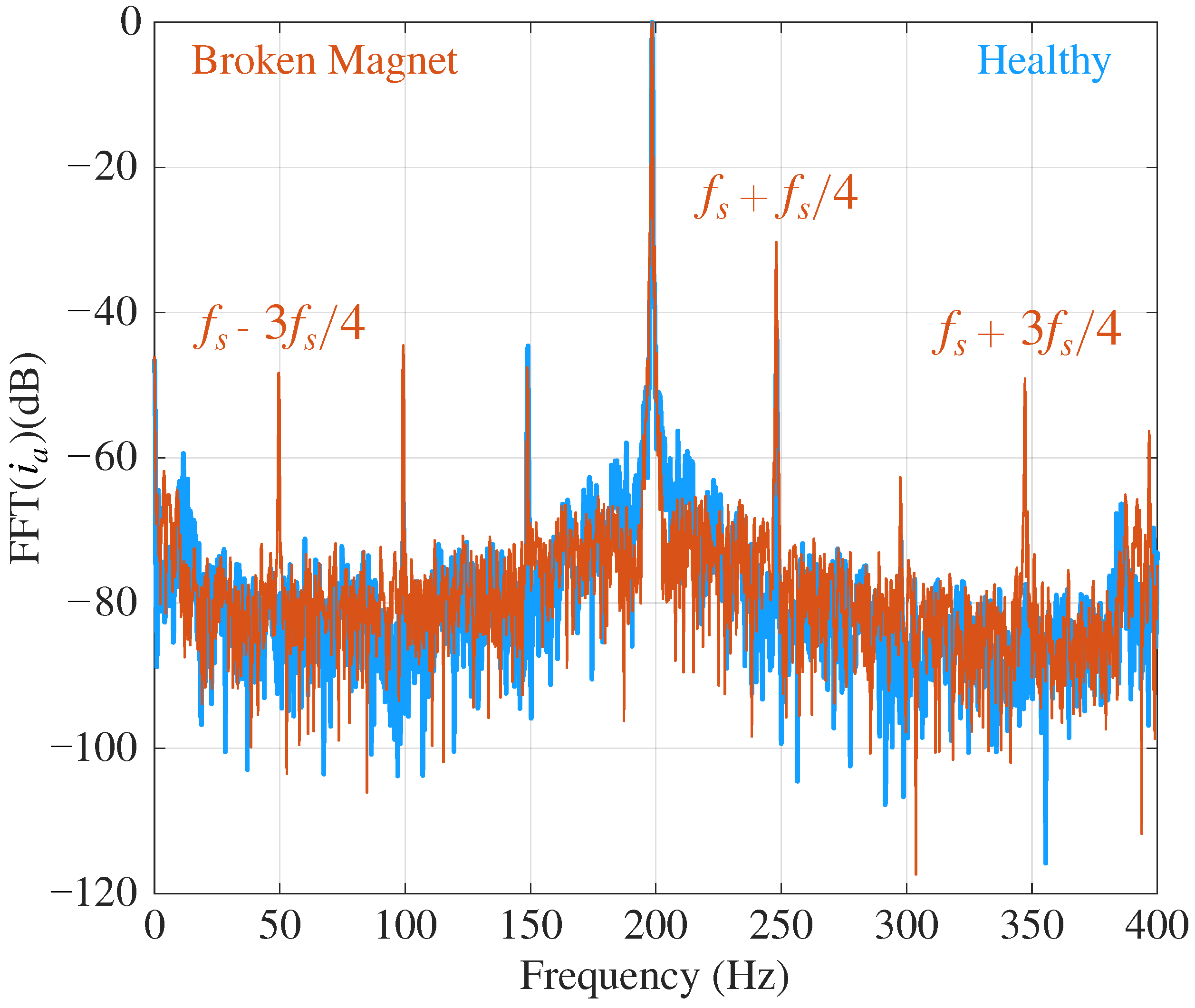
In Figure 10, the FFT of the measured stator phase current of the tested motor is presented in the frequency domain. It showcases the conditions of the motor with both a broken magnet and in a healthy state, operating at rated speed and torque. In the current spectrum, the signatures of the first and second harmonics show the broken magnet effects precisely.

Figure 10.
FFT of the phase-a current for healthy and broken magnet cases of the experimentally tested PMSM.
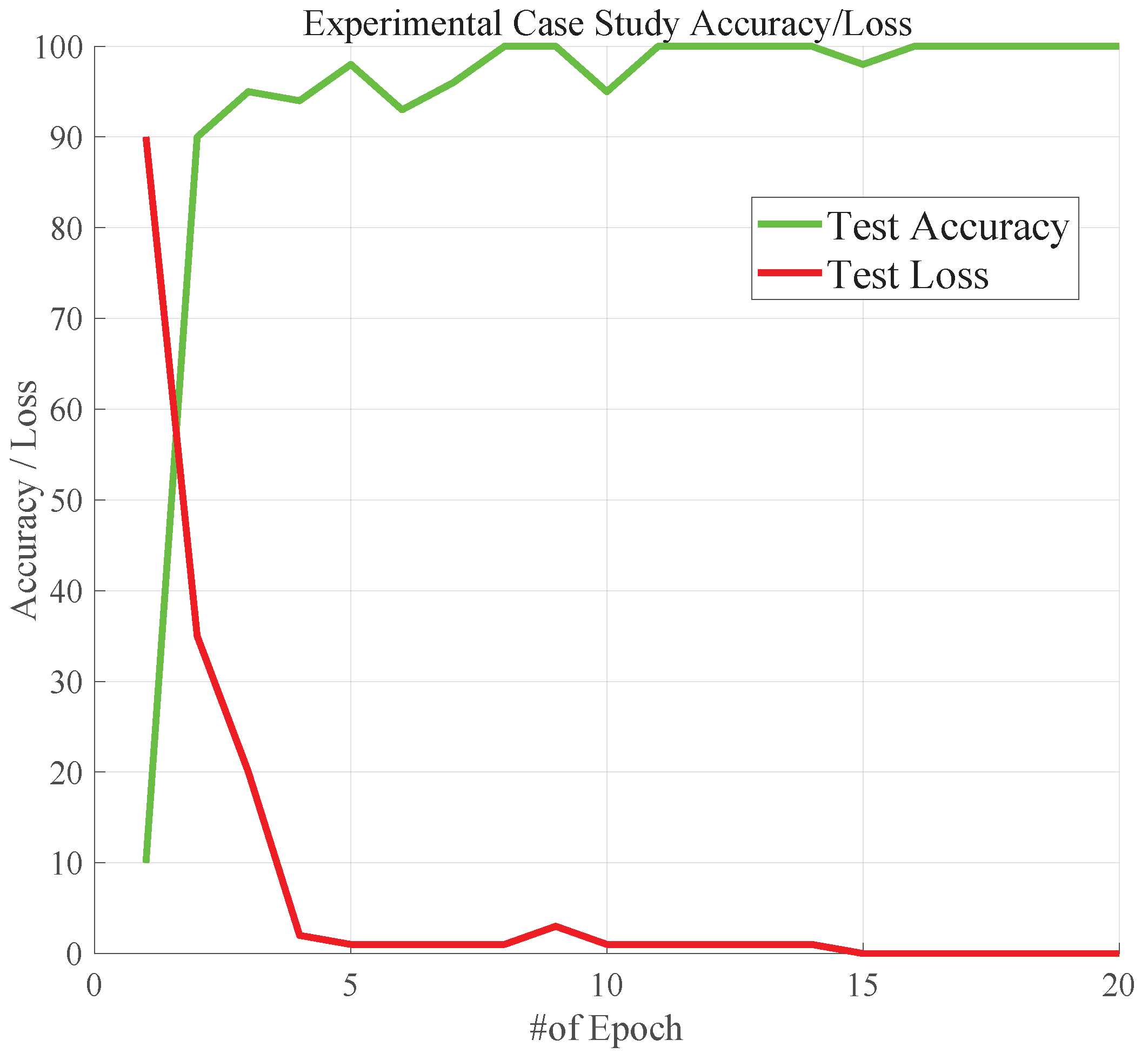
To evaluate the performance of the proposed pre-trained CNN model on the experimentally tested broken magnets, a comparative analysis was conducted to assess the performance of the proposed CNN model on both the experimental and simulation datasets. Figure 11 illustrates the loss and accuracy curves generated from experimental datasets.
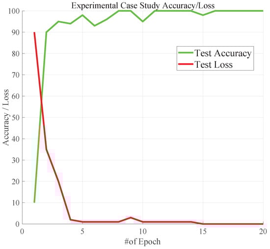
Figure 11.
Accuracy and loss curve of the proposed pre-trained AlexNet CNN model for experimental case study under simulation-matching conditions (speed: 3000 rpm and load: 1.28 N·m).
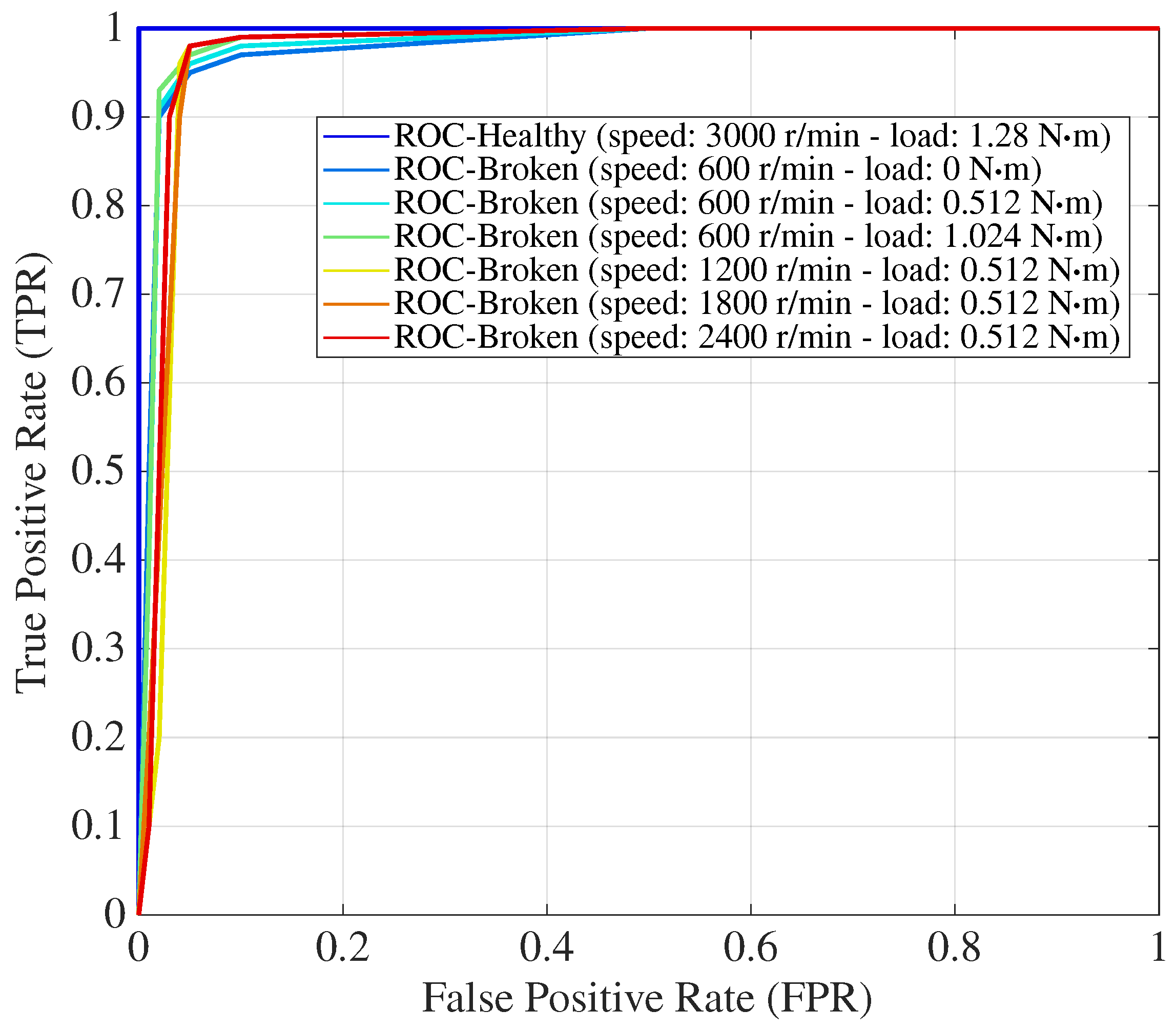
A striking alignment between the loss and accuracy curves obtained from the experimental dataset and those previously generated from the simulation dataset, as shown in Figure 6, was observed. This alignment suggests that the proposed CNN model consistently exhibited strong performance across both datasets. Such consistency underscores the robustness and reliability of the proposed pre-trained Alexnet CNN model in effectively classifying and detecting various levels of broken magnets. The aim of designing the experimental case study was to comprehensively evaluate the performance of the proposed CNN model in practical conditions. To achieve this, the load and speed conditions used in our simulation dataset were initially replicated to establish a baseline for comparison. By doing so, it was ensured that the proposed model was tested under conditions that closely mirrored the simulation environment, allowing an assessment of its ability to generalize from simulations to real-world scenarios. Furthermore, the importance of evaluating the proposed model’s robustness across a wider range of operating conditions was recognized. To this end, additional load and speed conditions were introduced beyond those used in the simulation dataset. Remarkably, the proposed model exhibited its best performance under these varying load and speed conditions, indicating its versatility and reliability in real-world applications. The inclusion of these extra conditions in the experimental case study further enhances the practical relevance of the findings, ensuring that the performance assessment of the proposed pre-trained AlexNet CNN model is comprehensive and representative of the challenges encountered in real-world motor systems. Additionally, a receiver operating characteristic (ROC) graph was employed to demonstrate the performance of the proposed model, as shown in Figure 12. The ROC graph is a powerful tool that illustrates the trade-off between the true positive rate (sensitivity) and the false positive rate (1-specificity) at different classification thresholds. In this context, the ROC graph is used to assess how well the model distinguishes between healthy and broken magnets at varying load and speed conditions.
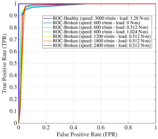
Figure 12.
Receiver operating characteristic (ROC) curve for experimentally tested broken magnets in different speed and load ranges.
The experimental dataset, which includes the measured stator phase current of the motor under different loads and speeds, was used to train the proposed CNN model with transfer learning techniques. The ROC graph plots the model’s performance for each load and speed condition, providing a comprehensive evaluation of its diagnostic capabilities. A higher area under the ROC curve (AUC) indicates that the model can effectively differentiate between healthy and broken magnets, regardless of the load and speed variations.
Remarkably, the ROC graph demonstrates that the proposed transferred CNN model achieves an AUC of 99.95%, signifying perfect discrimination between healthy and broken magnets across all tested conditions. This indicates that the model exhibited exceptional accuracy in classifying broken magnets, and its performance remained consistently robust under different load and speed scenarios, affirming its efficacy in real-world applications without imposing any significant computational burden.
6. Conclusions
In this study, a new pre-trained Alexnet CNN was investigated for the detection and classification of broken magnets in PMSMs. The proposed transferred CNN method offers several advantages over conventional tools, such as numerical models with computational burden or complex signal processing methods. In this advanced method, the examination of broken magnets of various shapes and damage percentages was conducted under different conditions to interpret the subtle variations in the spectrum. By creating a dataset from STFT graphical images, this proposed method achieved a validation accuracy of 99.23% and a training accuracy of 99.94% for the detection and classification of broken magnets. To demonstrate the consistency between the simulation and experimental results, the simulation scenarios were put into practice on the experimental setup. This automated identification and classification method was shown to aid in the early detection of broken magnets, offering the potential for effective early prevention. By defining the input–output parameters and integrating them as a sub-module within a fully automatic broken magnet detection system, this approach holds the potential to evolve into a comprehensive and fully automated system for detecting broken magnets. An intriguing avenue for future research involves exploring different DL architectures for the classification and identification of various broken magnets in different kinds of electrical machines. Additionally, comparing these designs to determine the optimal network for broken magnet detection is an important area of study. However, as we look toward the application of the proposed methodology in larger industrial or real-world schemes, several challenges and considerations come to the forefront. Firstly, real-world systems operate under a wide range of conditions, including varying loads, temperatures, and environmental factors. Adapting the proposed methodology to account for this variability and ensuring its robust performance under diverse conditions requires ongoing research and development. Furthermore, real-world data often contain noise, uncertainties, and sensor inaccuracies. Addressing the impact of these factors on the proposed methodology’s performance is crucial for its practical deployment. Techniques for noise mitigation and uncertainty handling merit exploration. To address these challenges, data augmentation to enhance dataset diversity, mechanisms for online learning and model adaptation to evolving conditions, and the integration of data from multiple sensors through sensor fusion in real-world industrial settings to validate the proposed methodology’s performance and identify practical challenges are recommended.
Author Contributions
Conceptualization, S.B.O. and A.G.M.; methodology, S.B.O. and A.G.M.; software, A.G.M.; validation, A.G.M. and S.B.O.; formal analysis, A.G.M.; investigation, A.G.M.; resources, A.G.M.; data curation, A.G.M., S.B.O. and T.G.; writing—original draft preparation, A.G.M. and S.B.O.; writing—review and editing, A.G.M., S.B.O., T.G. and O.H.; visualization, A.G.M. and S.B.O.; supervision, S.B.O. and T.G.; project administration, S.B.O. and T.G. All authors have read and agreed to the published version of the manuscript.
Funding
This research received no external funding.
Data Availability Statement
Data are contained within the article.
Acknowledgments
The authors acknowledge and appreciate the Flanders Make for their support of the MOBI research group.
Conflicts of Interest
The authors declare no conflicts of interest.
References
- Waide, P.; Brunner, C.U. Energy-efficiency policy opportunities for electric motor-driven systems. Energy Policy 2011, 39, 6444–6454. [Google Scholar] [CrossRef]
- Sheikh-Ghalavand, B.; Vaez-Zadeh, S.; Isfahani, A.H. An improved magnetic equivalent circuit model for iron-core linear permanent-magnet synchronous motors. IEEE Trans. Magn. 2009, 46, 112–120. [Google Scholar] [CrossRef]
- Rosero, J.A.; Cusido, J.; Garcia, A.; Ortega, J.; Romeral, L. Broken Bearings and Eccentricity Fault Detection for a Permanent Magnet Synchronous Motor. In Proceedings of the IECON 2006-32nd Annual Conference on IEEE Industrial Electronics, Paris, France, 6–10 November 2006; pp. 964–969. [Google Scholar] [CrossRef]
- Usman, A.; Joshi, B.M.; Rajpurohit, B.S. Review of fault modeling methods for permanent magnet synchronous motors and their comparison. In Proceedings of the 2017 IEEE 11th International Symposium on Diagnostics for Electrical Machines, Power Electronics and Drives (SDEMPED), Tinos, Greece, 29 August–1 September 2017; pp. 141–146. [Google Scholar] [CrossRef]
- Romero-Troncoso, R.J. Multirate signal processing to improve FFT-based analysis for detecting faults in induction motors. IEEE Trans. Ind. Inform. 2016, 13, 1291–1300. [Google Scholar] [CrossRef]
- Niu, G.; Son, J.D.; Yang, B.S. Performance Evaluation of Multi-sensors Signals and Classifiers for Faults Diagnosis of Induction Motor. In Proceedings of the Korean Society for Noise and Vibration Engineering Conference; Korea Institute of Science and Technology Information: Daejeon, Republic of Korea, 2006; pp. 411–416. [Google Scholar]
- Seera, M.; Lim, C.P.; Nahavandi, S.; Loo, C.K. Condition monitoring of induction motors: A review and an application of an ensemble of hybrid intelligent models. Expert Syst. Appl. 2014, 41, 4891–4903. [Google Scholar] [CrossRef]
- Gherabi, Z.; Toumi, D.; Benouzza, N.; Boudinar, A.H.; Koura, M.B. Discrimination between demagnetization and eccentricity faults in PMSMs using real and imaginary components of stator current spectral analysis. J. Power Electron. 2021, 21, 153–163. [Google Scholar] [CrossRef]
- Krichen, M.; Elbouchikhi, E.; Benhadj, N.; Chaieb, M.; Benbouzid, M.; Neji, R. Motor current signature analysis-based permanent magnet synchronous motor demagnetization characterization and detection. Machines 2020, 8, 35. [Google Scholar] [CrossRef]
- Strangas, E.G.; Aviyente, S.; Zaidi, S.S.H. Time-Frequency Analysis for Efficient Fault Diagnosis and Failure Prognosis for Interior Permanent-Magnet AC Motors. IEEE Trans. Ind. Electron. 2008, 55, 4191–4199. [Google Scholar] [CrossRef]
- Zanardelli, W.G.; Strangas, E.G.; Aviyente, S. Identification of intermittent electrical and mechanical faults in permanent-magnet AC drives based on time-frequency analysis. IEEE Trans. Ind. Appl. 2007, 43, 971–980. [Google Scholar] [CrossRef]
- Wang, C.; Liu, X.; Chen, Z. Incipient Stator Insulation Fault Detection of Permanent Magnet Synchronous Wind Generators Based on Hilbert-Huang Transformation. IEEE Trans. Magn. 2014, 50, 1–4. [Google Scholar] [CrossRef]
- Rosero, J.A.; Romeral, L.; Ortega, J.A.; Rosero, E. Short-Circuit Detection by Means of Empirical Mode Decomposition and Wigner-Ville Distribution for PMSM Running Under Dynamic Condition. IEEE Trans. Ind. Electron. 2009, 56, 4534–4547. [Google Scholar] [CrossRef]
- Ebrahimi, B.M.; Faiz, J. Feature Extraction for Short-Circuit Fault Detection in Permanent-Magnet Synchronous Motors Using Stator-Current Monitoring. IEEE Trans. Power Electron. 2010, 25, 2673–2682. [Google Scholar] [CrossRef]
- Park, J.K.; Hur, J. Detection of Inter-Turn and Dynamic Eccentricity Faults Using Stator Current Frequency Pattern in IPM-Type BLDC Motors. IEEE Trans. Ind. Electron. 2016, 63, 1771–1780. [Google Scholar] [CrossRef]
- Goktas, T.; Zafarani, M.; Akin, B. Discernment of broken magnet and static eccentricity faults in permanent magnet synchronous motors. IEEE Trans. Energy Convers. 2016, 31, 578–587. [Google Scholar] [CrossRef]
- Abdellatif, S.; Aissa, C.; Hamou, A.A.; Chawki, S.; Oussama, B.S. A Deep Learning Based on Sparse Auto-Encoder with MCSA for Broken Rotor Bar Fault Detection and Diagnosis. In Proceedings of the 2018 International Conference on Electrical Sciences and Technologies in Maghreb (CISTEM), Algiers, Algeria, 28–31 October 2018; pp. 1–6. [Google Scholar]
- Abid, F.B.; Sallem, M.; Braham, A. Robust interpretable deep learning for intelligent fault diagnosis of induction motors. IEEE Trans. Instrum. Meas. 2020, 69, 3506–3515. [Google Scholar] [CrossRef]
- Zhang, S.; Zhang, S.; Wang, B.; Habetler, T.G. Deep learning algorithms for bearing fault diagnostics—A comprehensive review. IEEE Access 2020, 8, 29857–29881. [Google Scholar] [CrossRef]
- Bhadra, R.; Dutta, S.; Kedia, A.; Gupta, S.; Panigrahy, P.S.; Chattopadhyay, P. Applied machine learning for bearing fault prognostics. In Proceedings of the 2018 IEEE Applied Signal Processing Conference (ASPCON), Kolkata, India, 7–9 December 2018; pp. 158–162. [Google Scholar]
- Yu, Y.; Gao, H.; Zhou, S.; Pan, Y.; Zhang, K.; Liu, P.; Madyira, D.M. Rotor Faults Diagnosis in PMSMs Based on Branch Current Analysis and Machine Learning. Actuators 2023, 12, 145. [Google Scholar] [CrossRef]
- Jeong, H.; Lee, H.; Kim, S.W. Classification and detection of demagnetization and inter-turn short circuit faults in IPMSMs by using convolutional neural networks. In Proceedings of the 2018 IEEE Energy Conversion Congress and Exposition (ECCE), Portland, OR, USA, 23–27 September 2018; pp. 3249–3254. [Google Scholar] [CrossRef]
- Kao, I.H.; Wang, W.J.; Lai, Y.H.; Perng, J.W. Analysis of permanent magnet synchronous motor fault diagnosis based on learning. IEEE Trans. Instrum. Meas. 2018, 68, 310–324. [Google Scholar] [CrossRef]
- Lee, H.; Jeong, H.; Kim, S.W. Detection of interturn short-circuit fault and demagnetization fault in IPMSM by 1-D convolutional neural network. In Proceedings of the 2019 IEEE PES Asia-Pacific Power and Energy Engineering Conference (APPEEC), Macao, China, 1–4 December 2019; pp. 1–5. [Google Scholar]
- Hang, J.; Shu, X.; Ding, S.; Huang, Y. Robust Open-Circuit Fault Diagnosis for PMSM Drives Using Wavelet Convolutional Neural Network With Small Samples of Normalized Current Vector Trajectory Graph. IEEE Trans. Ind. Electron. 2023, 70, 7653–7663. [Google Scholar] [CrossRef]
- Pietrzak, P.; Wolkiewicz, M.; Orlowska-Kowalska, T. PMSM Stator Winding Fault Detection and Classification Based on Bispectrum Analysis and Convolutional Neural Network. IEEE Trans. Ind. Electron. 2023, 70, 5192–5202. [Google Scholar] [CrossRef]
- Park, Y.; Fernandez, D.; Lee, S.B.; Hyun, D.; Jeong, M.; Kommuri, S.K.; Briz, F. Online detection of rotor eccentricity and demagnetization faults in PMSMs based on hall-effect field sensor measurements. IEEE Trans. Ind. Appl. 2018, 55, 2499–2509. [Google Scholar] [CrossRef]
- Ruiz, J.R.R.; Rosero, J.A.; Espinosa, A.G.; Romeral, L. Detection of demagnetization faults in permanent-magnet synchronous motors under nonstationary conditions. IEEE Trans. Magn. 2009, 45, 2961–2969. [Google Scholar] [CrossRef]
- Zamudio-Ramirez, I.; Osornio-Ríos, R.A.; Diaz-Saldaña, G.; Trejo-Hernández, M.; Antonino-Daviu, J.A. STFT-based induction motor stray flux analysis for the monitoring of cutting tool wearing in CNC machines. In Proceedings of the IECON 2020 The 46th Annual Conference of the IEEE Industrial Electronics Society, Singapore, 18–21 October 2020; pp. 2511–2516. [Google Scholar]
- Schafer, R.W.; Oppenheim, A.V. Discrete-Time Signal Processing; Prentice Hall: Englewood Cliffs, NJ, USA, 1989. [Google Scholar]
- Satpathi, K.; Yeap, Y.M.; Ukil, A.; Geddada, N. Short-time Fourier transform based transient analysis of VSC interfaced point-to-point DC system. IEEE Trans. Ind. Electron. 2017, 65, 4080–4091. [Google Scholar] [CrossRef]
- Pietrzak, P.; Wolkiewicz, M. Stator Winding Fault Detection of Permanent Magnet Synchronous Motors Based on the Short-Time Fourier Transform. Power Electron. Drives 2022, 7, 112–133. [Google Scholar] [CrossRef]
- ANSYS. Ansys Maxwell: Low Frequency Electromagnetic Field Simulation. Available online: https://www.ansys.com/Products/Electronics/ANSYS-Maxwell (accessed on 25 November 2023).
- Cao, Y.; Li, Q.; Yu, L. A Software for Design and Analysis of PMSM Based on ANSYS. In Proceedings of the 2009 First International Conference on Information Science and Engineering, Nanjing, China, 26–28 December 2009; pp. 78–81. [Google Scholar] [CrossRef]
- Wang, L.; Wang, X.; Zheng, Y.; Li, L.; Wang, W.; Wu, H. Finite Element Analysis of Permanent Magnet Synchronous Motor of Electric Vehicle. In Proceedings of the 2015 3rd International Conference on Advances in Energy and Environmental Science, Zhuhai, China, 25–26 July 2015; pp. 1127–1130. [Google Scholar]
- Howard, J.; Gugger, S. Fastai: A Layered API for Deep Learning. Information 2020, 11, 108. [Google Scholar] [CrossRef]
- Graf, L.; Bach, H.; Tiede, D. Semantic Segmentation of Sentinel-2 Imagery for Mapping Irrigation Center Pivots. Remote Sens. 2020, 12, 3937. [Google Scholar] [CrossRef]

Disclaimer/Publisher’s Note: The statements, opinions and data contained in all publications are solely those of the individual author(s) and contributor(s) and not of MDPI and/or the editor(s). MDPI and/or the editor(s) disclaim responsibility for any injury to people or property resulting from any ideas, methods, instructions or products referred to in the content. |
© 2024 by the authors. Licensee MDPI, Basel, Switzerland. This article is an open access article distributed under the terms and conditions of the Creative Commons Attribution (CC BY) license (https://creativecommons.org/licenses/by/4.0/).