Abstract
The paper presents a simulation-based approach for optimizing CO2 injection into depleted gas reservoirs, with the goal of enhancing underground CO2 storage. The research employs a two-dimensional dynamic reservoir model, developed using Darcy’s law, to describe gas flow in a pressure-homogeneous porous medium, along with real gas equations. The model integrates the Du Fort–Frenkel and finite-difference methods to accurately simulate the behavior of CO2 during injection and storage. Real data from an operational gas storage facility were used to calibrate the model. CO2sim v1 software, specifically developed for this purpose, simulates CO2 injection cycles and quiescence phases, enabling the optimization of storage capacity and energy efficiency. The reservoir model, based on the engineering of the geological structure, is discretized into approximately 16,000 cells and solved using the finite-difference method, allowing for rapid simulation of CO2 injection and quiescence processes. The average computation time for a 150-day cycle is approximately 5 min. Simulation results indicate that increasing the number of injection wells and carefully controlling the injection rates significantly improves the distribution of CO2 within the reservoir, thereby enhancing storage efficiency. Additionally, appropriate well placement and prolonged quiescence periods lead to better CO2 dispersion, increasing the storage potential while reducing energy costs. The study concludes that further development of the software, along with comprehensive technical and economic assessments, is required to fully optimize CO2 storage on a commercial scale.
1. Introduction
CO2 emissions, which account for 77% of all greenhouse gases [1], rose by 1.1% in 2023, hitting a record high of 37.4 Gt [2]. Despite its lower global warming potential (GWP) compared to other greenhouse gases, the vast amount of CO2 emitted makes it the most impactful for climate change mitigation [3,4]. Scientific consensus affirms that rising CO2 levels are a major driver of climate change [5]. To mitigate the impacts of global warming, the Paris Agreement aims to limit global temperature rise to below 2 °C, preferably 1.5 °C [6,7]. In support of this goal, various technologies have been proposed to capture and reduce CO2 emissions, with Carbon Capture and Storage (CCS) in underground geological formations being one of the most prominent solutions [8,9]. CCS is notable for its ability to capture large amounts of CO2 directly from industrial sources, offering a substantial and direct impact on emission reduction. This makes underground geological storage a particularly useful, effective, and economically viable approach, crucial for meeting the Paris Agreement targets [6]. The injected CO2 is securely stored through two primary trapping mechanisms: physical and geochemical trapping [4,10,11]. Physical trapping occurs when CO2 retains its physical state after injection into an aquifer and can be further divided into structural (hydrostratigraphic) and residual (capillary) trapping. In contrast, geochemical trapping happens when CO2 undergoes chemical reactions with the formation of brine and rock, changing its physical and chemical state, no longer remaining in a mobile or immobile phase [12]. Physical trapping is generally effective for less than a century, while geochemical trapping takes over in periods exceeding 100 years [4,10,11]. Numerous studies have assessed the performance of depleted gas reservoirs based on the aforementioned mechanisms. Jitmahantakul et al. [13] conducted numerical simulations of CO2 injection into a Permian carbonate reservoir in the Sin Phu Horm gas field, northeastern Thailand, using Schlumberger Petrel 2021.2 and ECLIPSE 2021.2 software for reservoir modeling and simulation. The primary goal of this simulation was to assess the cumulative CO2 stored after injection and predict the reservoir pressure over a 50-year period. The results showed that after 50 years of injection, the reservoir pressure increased from 170.85 bar to 189.60 bar, which is still below the initial pressure of 268.90 bar at the start of production. With an annual injection rate of 0.19 MtCO2, a total of 9.5 MtCO2 was injected into the reservoir.
Raza et al. [14] examined the impact of residual gas on key aspects of CO2 storage in dry gas reservoirs using Eclipse300™ for modeling. The findings highlighted the importance of selecting storage mediums based on the amount of residual gas to maximize the effective storage capacity and maintain sustainable injection rates. The study also revealed a direct relationship between the amount of residual gas and capillary trapping, while an inverse relationship was observed with injection rate sustainability, as well as with structural and dissolution trapping and the overall storage capacity.
Oh et al. [15] developed a Material Balance Equation (MBE) method to improve the accuracy of CO2 storage capacity estimates in saline aquifers. This method was applied to the upper sandstone layer of the Sleipner 2019 benchmark model, showing a high level of accuracy with a relative error of just 2.09% compared to the results from reservoir simulations. Additionally, the MBE method provided an accurate estimate of the CO2 storage capacity for the Sleipner L9 model case, with a relative error of only 3.47%.
He et al. [12] developed an analytical model to assess the CO2 storage potential in depleted gas reservoirs, incorporating CO2 dissolution in formation water based on the molar balance principle. The study revealed that accounting for CO2 dissolution significantly enhances the storage volume. For two wells, the CO2 storage volumes increased from 12.31 × 10⁴ t and 4.31 × 10⁴ t without CO2 dissolution to 14.18 × 10⁴ t and 6.16 × 10⁴ t, respectively, when dissolution was considered. This approach aimed to refine initial static estimates of the CO2 storage capacity and improve the understanding of reservoir behavior.
Mortensen et al. [16] investigated two saline aquifers in southern Sweden, using the basin modeling program SEMI to estimate the capacities of structural and stratigraphic traps and the dynamic reservoir simulation program ECLIPSE 100 for more detailed capacity assessments. The study revealed significant differences in the CO2 storage capacities [17,18]. SEMI, which focused on structural and stratigraphic traps, provided relatively low capacity estimates, while ECLIPSE 100, which incorporated all major trapping mechanisms, resulted in much higher capacity estimates [16].
Dumitrache et al. [19] used Eclipse and Petrel to assess the possibility of CO2 capture in an underground storage reservoir from Romania. Also, Afolayan et al. simulated the dynamic modeling of geological carbon storage in an oil reservoir from South Africa using the CMG-GEM compositional simulator [20]. Figure 1 shows the steps involved in carrying out the study.
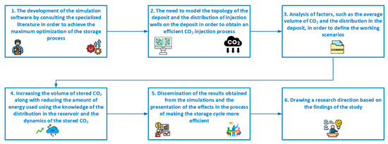
Figure 1.
Graphic abstract of the article (source: authors, based on article content).
Our study aims to present the software CO2sim v1, which was created by the authors, how to use it, its capabilities, the work interface, as well as the mechanism of the equations and physical–mathematical laws that are the basis of the simulation process.
The CO2 storage process along with the redistribution of gas in the reservoir based on CO2 migration will ensure the best decisions for its management.
2. Methodology
To carry out the study, real data were needed to describe the average parameters of the deposit, the initial pressures, the gas cushion, the average seasonal flow for the injection cycle, the average period for the storage cycle, and the period in which the system is in equilibrium. The data used to initiate this study were provided by the company that owns the deposits. A problem addressed in the case of the study was the realization of a set of simulations in order to optimize and make the CO2 injection cycle in the deposit more efficient.
The study carried out is based on well-established implementation steps based on a working methodology:
- The development of the simulation software by consulting the specialized literature in order to achieve the maximum optimization of the storage process;
- The need to model the topology of the deposit and the distribution of injection wells on the deposit in order to obtain an efficient CO2 injection process;
- An analysis of factors, such as the average volume of CO2 and the distribution in the deposit, in order to define the working scenarios;
- Increasing the volume of stored CO2 along with reducing the amount of energy used using the knowledge of the distribution in the reservoir and the dynamics of the stored CO2;
- Dissemination of the results obtained from the simulations and the presentation of the effects in the process of making the storage cycle more efficient;
- Drawing a research direction based on the findings of the study.
3. Software Description
3.1. Short Description of the Model behind the Simulator
The flow equations in Cartesian coordinates were used to simulate the processes that take place in a horizontal plane.
The two-dimensional movement of gases in a pressure-homogeneous porous medium is described by DARCY’s equation, the continuity equation, and the equation of state of real gases). A more comprehensive presentation of the theoretical basis and control equations and methodology for implementation is presented in another article.
The Du Fort–Frankel integration method is unconditionally stable with two temporary steps, which make it ideal for use in the case of the chosen gas reservoir. Written in finite differences so that it can be integrated over the domain represented by the reservoir, the equation allows for the rapid determination, at each moment of time, of the pressure field.
For the calculation of the variable at the next time step, information from two previous moments of time was used, which represents a disadvantage of this scheme, and in conclusion, it is necessary to use another method that allows for the calculation of the values at the moment of time based on the values of the previous moment, with the chosen method being the fundamental explicit method.
For the integration process, we need to define initial conditions and boundary conditions. This opens the path to define different simulation scenarios for the working model.
Initial conditions try to replicate the parameters from which the integration procedure starts. Hence, the injection of gas into the deposit begins from certain parameters, pressure, and volume of gas cushion. At the beginning of the injection process, the pressure is considered to be uniformly distributed at the reservoir level.
Boundary conditions define how the integration process proceeds, and at the reservoir level, integration blocks can be of several types. Two types of boundary conditions are used for the gas reservoir model: boundary conditions and wellbore boundary conditions. If the block contains an injection probe, then a quantity of CO2 enters through that block.
The pressure required for the CO2 injection is superimposed on the existing pressure in the reservoir (wellbore pressure).
The pressure generated by the mass flow of injected CO2 accumulates with the pressure at the base of the well. In each block where a well is placed, the pressure condition resulting from the injected flow rate is applied.
Given that we are dealing with a depleted gas field, its boundary is considered impermeable. The boundary condition on the boundary of the domain is imposed as the zero value of the gas velocity between it and the adjacent block in the deposit. For the flat bed case, the velocity along the Ox axis and the velocity along the Oy axis are zero.
In the case of depleted reservoirs, the commercial balance is reflected by the gas flows going through the existing wells.
The well boundary condition addresses the flow of CO2 circulated and that depends on the dimensions of the well, pressure, and layer permeability. Thus, a CO2 flow is imposed, and the model will calculate the pressure that ensures the circulation of that flow through the well. The flow injected through the well is divided into four flows to the neighboring nodes. In the event that the deposit is in the extraction phase, the boundary condition remains unchanged. However, the flow rate extracted by the well is entered as negative. For the situation where the deposit is in the quiet phase, the pressure in the deposit tends to equalize.
The software is built to simulate dynamic processes, so the integration process is performed for each time step as follows:
- Imposition of initial conditions on the entire deposit;
- Imposition of boundary conditions in wells and on the boundary;
- Generation of the system of equations related to the geometry of the deposit;
- Solving the system of equations;
- Generation of the pressure field from the deposit;
- Completion of the next time step and repeat of steps 2–5.
The calculation model takes into account the composition of the injected gas mixture.
For the calculation of the gas mixing process in the reservoir, the mass composition of the gas is defined in each of its blocks. For each time step, the composition calculation is conducted simultaneously with the pressure calculation on the entire reservoir. Following the mass balance on its blocks, the new composition of the deposit block is determined. The mass flows were defined according to the notations in Figure 2.
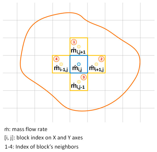
Figure 2.
Mass balance on the blocks in the deposit.
The gas mass of the block is determined with the value of the density at the previous time step. Using the mass balance of the block, its new composition can be calculated. Only positive mass fluxes (entering the block) are considered because they bring the new composition. Negative gas flows leave the block with its composition and will be taken into account in neighboring blocks.
For the numerical model to simulate the real geometry of the reservoir, the domain of integration for the model should be similar to the geometry of the deposit, which is achieved by defining a computer map of the domain.
By assigning characteristic information to each pixel on the drawing, the border points, the points corresponding to the probes, the points in the integration domain, and the points outside the integration domain each received an attribute. Thus, through the automatic processing of the domain image, a discrete network of points with various attributes results.
The integration process is carried out concurrently with the reading of the domain map. Information kept in this structure enables the calculations to be focused. Thus, in the points inside the reservoir, the integration process is carried out; in others, the conditions are set on the contour or the conditions at the wells, and no operation is carried out outside the deposit.
3.2. CO2sim v1 Software Capabilities
Numerical modeling of gas deposits consists in making a computer model whose domain reflects the geometry of the deposit, including the restrictions imposed by the properties of the rocks, and in which fluid movements can be defined. Numerical simulations are carried out on the computer model of the deposit with the aim of predicting the behavior of the deposit in different situations that are defined by the boundary conditions.
Designing the exploitation of the field over different time intervals and for different gases, such as CO2, can be achieved using numerical simulations.
Lately, numerical simulators are used more and more often for the operation of gas field exploitation or storage processes, but also for CO2 storage.
In order for the obtained results to be reproduced accurately, the numerical simulator must be calibrated with real data. This calibration process adapts the values of certain reservoir properties (such as permeability, porosity, and viscosity) to the values used on the model. The calibration of the model is performed by simulating a process on it so that the values resulting from the model are similar to the real ones. The comparison of the cumulative CO2 injected in the model and the values realized on the real deposit and the coincidence of the load curves of the deposit and the model show that the numerical simulator is calibrated. The calibration of the numerical simulator is carried out periodically for an improved accuracy of the obtained data.
To build the simulation software CO2sim v1, we started from a variant used only for natural gas and modified it for the possibility of CO2 injection. It works from the actual geometry of a planar reservoir, and because it has a comparable width, a two-dimensional model was created. Figure 3 shows an image from the software with the location of the wells and the outline of the deposit.
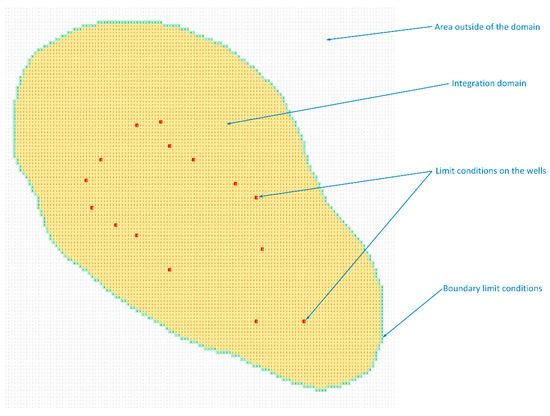
Figure 3.
Extracted CO2sim v1 image, with the location of the wells and the outline of the deposit.
The definition of the computer map of the domain is attained by assigning different attributes (see Figure 3) for the points inside the deposit (2), the border (1), the position of the probes (3), and the points outside the deposit (0). These are essential for introducing boundary conditions on the contour and in the well, allowing for the organization of the calculations for integration domains with different geometries.
The economic operator is the one who provided us with the real data regarding the composition of the gaseous mixture existing in the reservoir by providing us with the chromatographic bulletins, which is the software that allows loading for different compositions of the gas mixtures. Table 1 shows a sample report used in the simulation software.

Table 1.
Natural gas composition from the reservoir used in the analysis.
In our case, we simulated the injection process for natural gas in the reservoir and obtained the same results as in the real process and other known simulators. As the injection of CO2 was not made carried out in this reservoir, we cannot completely verify the results obtained. As initial data for the implementation of our study regarding the realization of the simulation process, we defined the initial conditions that show the starting state of the simulation and the boundary conditions on the contour of the deposit and in the injection wells. The reservoir is at an initial pressure. The rocks that make up the outline of the deposit are impermeable when we refer to deposits depleted of natural gas, and the velocity of the gaseous mixture on the outline of the deposit is zero. The dimensions of the well, the pressure of the reservoir, and the permeability of the layer influence the injection or extraction flow rate, which represents the limit value in the well. The model will generate the pressure that makes possible the circulation of the imposed flow over the probe. The model is able to present a spatial image of gas pressure distribution in the reservoir (Figure 4) and CO2 concentration distribution (Figure 5). Both figures present a 2D view, a horizontal plane through the reservoir, and the values obtained from the simulation for each cell of the grid for different parameters, pressures, or CO2 concentrations in this case. Outside the reservoir, we will have a 0 value, on the margins, the initial pressure (10 bar) or CO2 concentration (0.04), and in the interior of the reservoir (the integration area), different values that rise as we approach the position of a well. Based on these values and their dynamics in time and space, we construct the 3D graphs presented below.
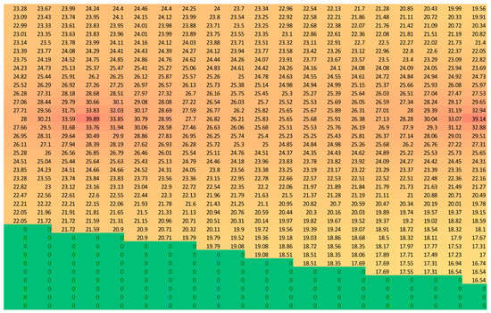
Figure 4.
The 2D gas pressure distributions in the deposit.
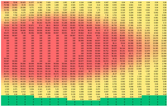
Figure 5.
The 2D distribution of CO2 concentrations in the deposit.
Both during the injection period and during the quiescence phase, CO2 migrates towards the reservoir boundary, but due to the location of the wells, a significant portion of the reservoir remains unused.
CO2sim v1 software allows for visualization in a 3D graphic form of the distribution of pressures (Figure 6) and CO2 (Figure 7) in the reservoir. The surface heights signify the well pressure or the maximum CO2 concentration. The colors in the pictures represent the distribution values for pressure or CO2 concentration starting from the lower value with blue and going to maximum value that is with burgundy as it is presented in the right part of the Figure 6.
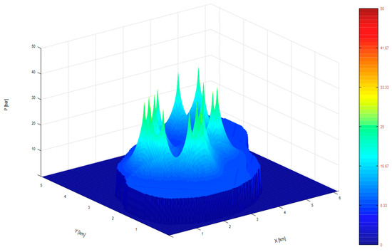
Figure 6.
The 3D reservoir pressure distribution.
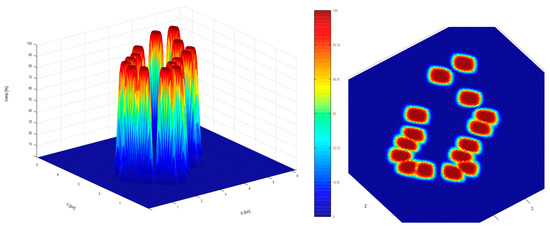
Figure 7.
The 3D (left) and 2D (right) CO2 concentrations in the reservoir.
An important non-uniformity is highlighted at the end of the injection cycle (Figure 7 right), making an analysis of the spatial distribution of CO2 in the deposit. At the deposit level, the filtration speed is low, and in order to make filling the deposit more efficient, there should be a long period of time in the quiet phase, which is not optimal from the storage perspective. Of utmost importance is the correct distribution of the newly built wells, as well as establishing the maximum injected flow to cover the deficient areas, reaching a significant increase in the storage capacity and the gas volume that can be put in storage.
CO2sim v1 software, even though it does not have the easiest interface in the case of designing the reservoir and its 3D shape compared to other simulators like Eclipse or Petrel, it compensates with its fast simulations and very low license costs. Being software in development, we are focusing in upgrading and extend the capabilities and modules, for example, a cost–benefit analysis module.
3.3. Outcomes of the Simulation
The simulation was carried out on a depleted deposit where sedimentary deposits belonging to the Pliocene, Sarmatian, Buglovian, and Badenian ages were crossed through exploration research wells, within a maximum depth of 3200 m.
Gas accumulations are located, for the most part, in structural traps and in combined traps. From a tectonic point of view, the structure is in the form of an elongated dome in the NW-SE direction, consistent in its depth and with relatively low inclinations of 2–4°.
The Va package of the Sarmatian stack, Sa-Va, is considered as a single hydrodynamic unit, and due to the special lithological character, a vertical saturation limit was drawn on the −900 m isobath, on the southwestern and northwestern flanks of the structure, and further inland (up to—882 m) on the other flanks.
To carry out the numerical simulation of the storage process, the geological model was recreated on the computer. As a result of this process, new physical–geological parameters were obtained for the studied objective.
For porosity and permeability, variation maps of these properties were made, based on core analyses and flow tests (for permeability).
From one of the newly drilled wells, core samples were extracted, and a complex geophysical investigation, interpreted petrophysically, was carried out. The porosity values obtained from the core analyses fall between the values of 20 and 26%, confirming the values estimated for the respective area from the porosity maps made. From the petrophysical analysis, instead, low porosity values were obtained, between 12 and 18%, with these values being too low compared to those obtained from the core analyses. Permeability values are on average between 10 and 70 mD.
The initial reservoir pressure was 13.9 MPa, at Sa-Va. The deposit temperature was 43 °C.
The underground natural gas storage facility has a capacity of 300 Million Sm3.
Fifteen injection/extraction probes are used in the storage process. The current maximum daily injection rate is approximative 2.6 Million Sm3/day.
To highlight the results of the process, it was considered that equal flows of 120,000 Sm3/day CO2 are injected through all 15 wells in the deposit (Figure 8). The initial pressure is 10 bar and is considered constant throughout the deposit.
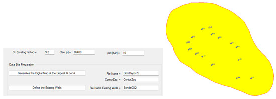
Figure 8.
The distribution of wells in the reservoir and inputs in the CO2sim v1 simulator.
The analysis at different periods of time gives us clear indications on the increase in the amount of stored CO2. The results obtained every 30 days of the entire storage process are presented as comparisons in Figure 9, Figure 10, Figure 11 and Figure 12.
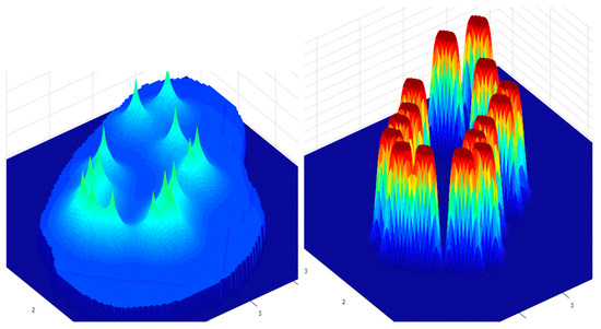
Figure 9.
Distributions of pressures (left) and CO2 in the reservoir (right) after 30 days.
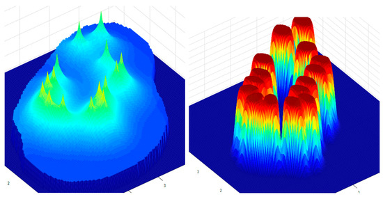
Figure 10.
Distributions of pressures (left) and CO2 in the reservoir (right) after 60 days.
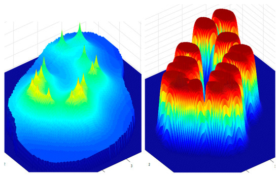
Figure 11.
Distributions of pressures (left) and CO2 in the reservoir (right) after 90 days.
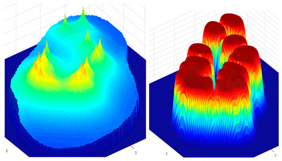
Figure 12.
Distributions of pressures (left) and CO2 in the reservoir (right) after 120 days.
The pressure increases faster in the central area due to the high density of the probes and the low gas filtration rate. Also, the concentration of CO2 in the area of the wells is very high.
The simulation results show a parabolic increase in the average pressure in the wells and also in the average pressure in the reservoir over time starting from 38 bar and 15 bar, as shown in Figure 9 for 30 days of injection, 40 bar and 19 bar after 60 days (Figure 10), 42 bar and 20.2 after 90 days (Figure 11), and, finally, 44 bar and 22 bar after 120 days (Figure 12). As was expected, the flow through the pore is limited because of the reservoir parameters. In this case, we used, in the simulations, an average permeability of 100 mD and a porosity of 22%. Thus, the rise in the pressure is more evident around the wells and dissipates along the reservoir to its boundaries, as can be seen in Figure 13 on the left in red color.
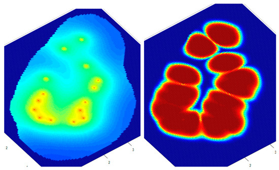
Figure 13.
The 2D distributions of pressures (left) and CO2 in the reservoir (right) after 120 days.
If we change the angle from which we look at the distribution of pressure and CO2 distributions in the reservoir, i.e., from 3D to 2D, at the end of the injection period, we can observe an uneven loading of the reservoir (Figure 13). This can be also seen for pressure in Figure 4 and CO2 concentration in Figure 5, as they depend on the position of the wells in the reservoir. Around the wells, the CO2 composition is 100% and decreases with the distance and can even reach 0% if the well is far from the boundary of the reservoir, as is the case here because of the well distribution that is not quite the best.
In order to see the effects of the time evolution of the two distributions, a quiet period of 10 days was simulated. After this phase, pressure equalization can be observed in the area of the injection wells, as well as the migration of CO2 from the wells to the neighboring areas (Figure 14).
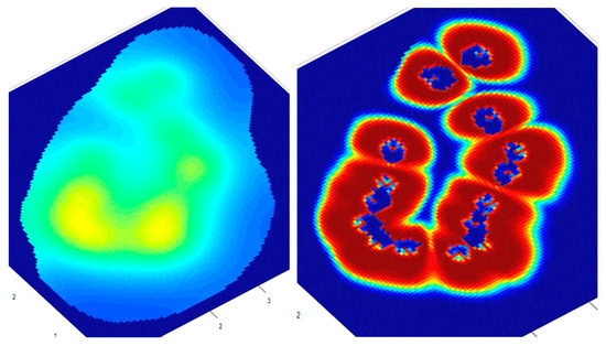
Figure 14.
The 2D distributions of pressures (left) and CO2 in the reservoir (right) after 130 days (10 days break).
The migration of CO2 due to the filtration velocities can be seen from the analysis of the spatial distribution compared to the previous case.
Given the short quiescence period, the CO2 does not travel very far to the reservoir boundary. For a better analysis and verification of the hypotheses formulated by other researchers, two more simulations were conducted for calm periods of 10 days each, with the results of the pressure and CO2 distribution being presented in Figure 15 and Figure 16.
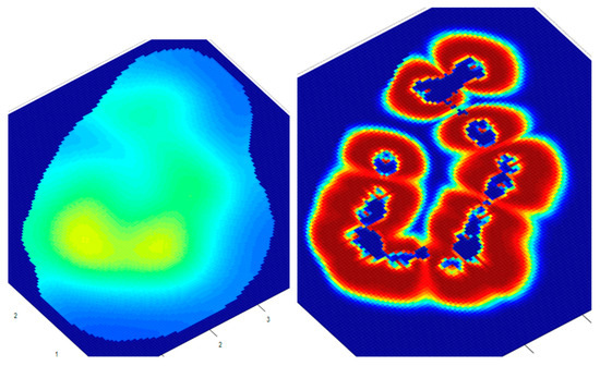
Figure 15.
The 2D distributions of pressures (left) and CO2 in the reservoir (right) after 140 days (20 days break).
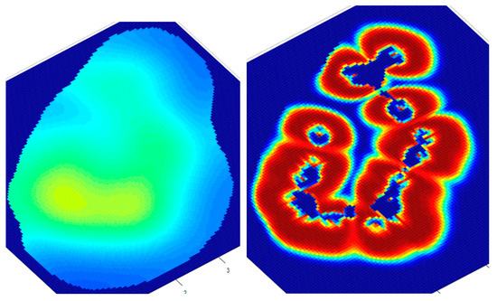
Figure 16.
The 2D distributions of pressures (left) and CO2 in the reservoir (right) after 150 days (30 days break).
As can be seen in the following figure, the simulator offers the possibility of simulating CO2 injection, simulating a quiet period for the deposit and then continuing the injection (Figure 17). This proves very useful considering the observations in Figure 16, where the CO2 drops a lot in the area of the wells. By re-injecting CO2 into the reservoir for another 50 days with the same flow rates, we obtain the profiles in Figure 18.

Figure 17.
Simulation inputs.
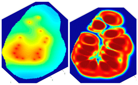
Figure 18.
The 2D distributions of pressures (left) and CO2 in the reservoir (right) after 200 days.
Thus, a much better distribution of CO2 is observed due to the quiet period, during which it migrated to the outside of the deposit.
The analysis of the simulation data of the CO2 storage processes, shown in Figure 19, shows the variation of the cumulative injected CO2 that reaches approximately 214 million Sm3, and the average pressure in the deposit reached 22 bar.
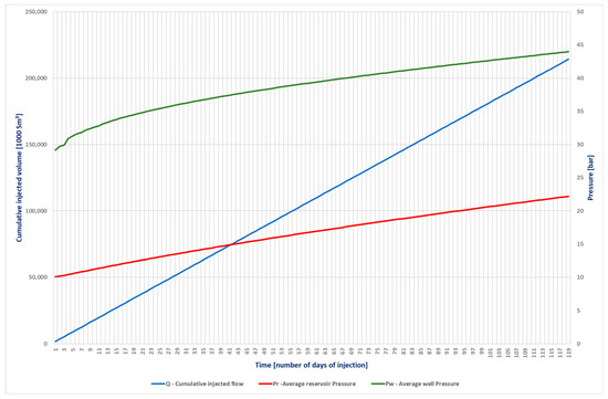
Figure 19.
The variations in the cumulative CO2 injected and the average pressure in the deposit and wells.
4. Discussion
The actions aimed at promoting energy efficiency, reducing the carbon footprint, and increasing renewable energy sources will contribute both to reducing the negative impact on the environment and to increasing security in the energy supply, reducing Romania’s degree of dependence on gas imports.
In general, the most economical way to increase the delivery capacity of the deposits is to increase the volume of the gas cushion, which automatically implies an increase in the pressure level, generating increased energy support on the basis of which larger quantities can be obtained over the same period of the extraction cycle. This can also be achieved by injecting CO2 into the reservoir.
The two-dimensional unsteady reservoir model used as a depleted reservoir, based on the geometry of the geological structure, is divided into approximately 16,000 cells and solved using the finite difference method. It allows for rapid simulation of CO2 injection, quiescence, and re-injection processes. The average simulation time of a 150-day cycle is 1 min. The model allows for spatial visualization of the CO2 distribution in the reservoir at each time point of the simulation.
Based on a numerical model for gas fields that takes into account the geometry of the field and the properties of the rocks, and in which the movements of the gases can be described, a simulator was built that allows for the dynamic simulation of the injection, quieting, and re-injection processes of both natural gas and CO2. For the case where the deposit is in the quiet phase, the pressure in the deposit tends to equalize.
Since the CO2 capture process is not uniform and depends a lot on industrial processes, the possibility of requesting that the deposit temporarily increases the injected flows in a certain period or the possibility of intermittent injection should be known. Both variants can be simulated with the built software.
Research can continue in the direction of drawing some curves that connect the injected flow rates, the amount of CO2, and the average pressure in the deposit, allowing us to quickly determine the average daily flow per injected well, so that at the end of the injection cycle, we can obtain a certain pressure in the deposit.
Knowing the spatial distribution of CO2 in the deposit, an optimal loading can be calculated for the uniformity of its filling, thus opening new directions for software development. One direction would be the possibility of introducing new wells in the deficit areas, leading to the increase in both the amount of stored CO2 and the average pressure in the deposit due to a much more efficient distribution on the deposit surface. The second direction of research development based on the software’s capability is represented by the much more accurate distribution of injected volumes by using customized flow rates for each well, depending on its position in the reservoir and the distribution and migration of gases in it.
The studies regarding the capture and storage process of CO2 must take into account the amortization period of the costs, and in this sense, steps must be taken to carry out technical-economic studies.
5. Conclusions
An original two-dimensional, non-stationary, variable-geometry numerical model for a depleted gas reservoir to store CO2 was created. It allows for the everyday calculation of the pressure matrix, CO2 saturation, and gas volumes anywhere in the reservoir, and its representation is in 3D/2D graphic forms.
The developed software can be used for the verification and validation of depleted deposits that lend themselves to being transformed into underground CO2 storage sites.
By analyzing the obtained results, one can acknowledge the veracity of the storage optimization process because the average pressure in the reservoir has increased even the average pressure of the wells is decreasing, which means a much lower energy consumption per well, in conjunction with the increase in the amount of stored CO2.
The increase in the number of wells, although requiring large investments, can lead to additional revenues due to the volumes of CO2 stored but also to the provision of storage possibilities in various areas of the deposit depending on the distribution and price of CO2.
CO2sim v1 is not yet fully developed. In addition to increasing the flexibility of flows injected through wells, we desire to improve it with a technical-economic module that will bring added value for decision makers in companies.
Author Contributions
Conceptualization, C.N.E., R.D., S.S. and D.B.S.; methodology, C.N.E., R.D., I.V.G., A.P., I.G.S. and D.B.S.; software, D.B.S. and C.N.E.; validation, C.N.E., R.D., S.S. and L.D.; formal analysis, S.S., R.D., I.V.G., A.P., I.G.S. and L.D.; investigation, C.N.E., R.D., D.B.S., A.P., I.G.S. and I.V.G.; resources, D.B.S., C.N.E., R.D., A.P., I.G.S. and L.D.; data curation, I.G.S., I.V.G., D.B.S. and C.N.E.; writing—original draft preparation, C.N.E., R.D., S.S. and A.P.; writing—review and editing, C.N.E., R.D., S.S., I.G.S. and D.B.S.; visualization, C.N.E., S.S., D.B.S., R.D., A.P., I.G.S. and I.V.G.; supervision, C.N.E. and S.S.; project administration, C.N.E. and S.S.; funding acquisition, C.N.E. and S.S. All authors have read and agreed to the published version of the manuscript.
Funding
This research was funded by the financing contract GO-GICS no. 11062/08.06.2023 from Petroleum Gas University of Ploiesti, entitled “Aplicatie software pentru calculul/modelarea înmagazinării subterane a CO2” (Software application for calculation/modelling of underground CO2 storage).
Data Availability Statement
The original contributions presented in the study are included in the article, further inquiries can be directed to the corresponding author.
Conflicts of Interest
The authors declare no conflicts of interest.
References
- Rahman, F.A.; Aziz, M.M.A.; Saidur, R.; Bakar, W.A.W.A.; Hainin, M.R.; Putrajaya, R.; Hassan, N.A. Pollution to solution: Capture and sequestration of carbon dioxide (CO2) and its utilization as a renewable energy source for a sustainable future. Renew. Sustain. Energy Rev. 2017, 71, 112–126. [Google Scholar] [CrossRef]
- International Energy Agency. CO2 Emissions in 2023; International Energy Agency: Paris, France, 2024. [Google Scholar]
- Vallero, D.A. (Ed.) Chapter 8—Air pollution biogeochemistry. In Air Pollution Calculations; Elsevier: Amsterdam, The Netherlands, 2019; pp. 175–206. [Google Scholar]
- Ajayi, T.; Gomes, J.S.; Bera, A. A review of CO2 storage in geological formations emphasizing modeling, monitoring and capacity estimation approaches. Pet. Sci. 2019, 16, 1028–1063. [Google Scholar] [CrossRef]
- Intergovernmental Panel on Climate Change. Climate Change 2021—The Physical Science Basis; Intergovernmental Panel on Climate Change: Geneva, Switzerland, 2023. [Google Scholar]
- UNFCCC. Paris Agreement to the United Nations Framework Convention on Climate Change; Phoenix Design Aid: Randers, Denmark, 2015. [Google Scholar]
- IPCC. Global Warming of 1.5 °C IPCC Special Report on Impacts of Global Warming of 1.5 °C above Pre-Industrial Levels in Context of Strengthening Response to Climate Change, Sustainable Development, and Efforts to Eradicate Poverty; Cambridge University Press: Cambridge, UK, 2022. [Google Scholar]
- Martin-Roberts, E.; Scott, V.; Flude, S.; Johnson, G.; Haszeldine, R.S.; Gilfillan, S. Carbon capture and storage at the end of a lost decade. One Earth 2021, 4, 1569–1584. [Google Scholar] [CrossRef]
- Ali, M.; Jha, N.K.; Pal, N.; Keshavarz, A.; Hoteit, H.; Sarmadivaleh, M. Recent advances in carbon dioxide geological storage, experimental procedures, influencing parameters, and future outlook. Earth-Sci. Rev. 2022, 225, 103895. [Google Scholar] [CrossRef]
- Massarweh, O.; Abushaikha, A.S. CO2 sequestration in subsurface geological formations: A review of trapping mechanisms and monitoring techniques. Earth-Sci. Rev. 2024, 253, 104793. [Google Scholar] [CrossRef]
- Bashir, A.; Ali, M.; Patil, S.; Aljawad, M.S.; Mahmoud, M.; Al-Shehri, D.; Hoteit, H.; Kamal, M.S. Comprehensive review of CO2 geological storage: Exploring principles, mechanisms, and prospects. Earth-Sci. Rev. 2024, 249, 104672. [Google Scholar] [CrossRef]
- He, Y.; Liu, M.; Tang, Y.; Jia, C.; Wang, Y.; Rui, Z. CO2 storage capacity estimation by considering CO2 Dissolution: A case study in a depleted gas Reservoir, China. J. Hydrol. 2024, 630, 130715. [Google Scholar] [CrossRef]
- Jitmahantakul, S.; Chenrai, P.; Chaianansutcharit, T.; Assawincharoenkij, T.; Tang-on, A.; Pornkulprasit, P. Dynamic estimates of pressure and CO2-storage capacity in carbonate reservoirs in a depleted gas field, northeastern Thailand. Case Stud. Chem. Environ. Eng. 2023, 8, 100422. [Google Scholar] [CrossRef]
- Raza, A.; Gholami, R.; Rezaee, R.; Bing, C.H.; Nagarajan, R.; Hamid, M.A. CO2 storage in depleted gas reservoirs: A study on the effect of residual gas saturation. Petroleum 2018, 4, 95–107. [Google Scholar] [CrossRef]
- Oh, H.; Yoon, H.; Park, S.; Kim, Y.; Choi, B.; Sun, W.; Jeong, H. Estimation of CO2 storage capacities in saline aquifers using material balance. Fuel 2024, 374, 132411. [Google Scholar] [CrossRef]
- Mortensen, G.M.; Bergmo, P.E.S.; Emmel, B.U. Characterization and Estimation of CO2 Storage Capacity for the Most Prospective Aquifers in Sweden. Energy Procedia 2016, 86, 352–360. [Google Scholar] [CrossRef]
- Li, Q.; Cheng, Y.; Li, Q.; Zhang, C.; Ansari, U.; Song, B. Establishment and evaluation of strength criterion for clayey silt hydrate-bearing sediments. Energy Sources Part A Recovery Util. Environ. Eff. 2018, 40, 742–750. [Google Scholar] [CrossRef]
- Li, Q.; Wang, Y.; Wang, F.; Wu, J.; Usman Tahir, M.; Li, Q.; Yuan, L.; Liu, Z. Effect of thickener and reservoir parameters on the filtration property of CO2 fracturing fluid. Energy Sources Part A Recovery Util. Environ. Eff. 2019, 42, 1705–1715. [Google Scholar] [CrossRef]
- Dumitrache, L.N.; Suditu, S.; Ghețiu, I.; Pană, I.; Brănoiu, G.; Eparu, C. Using Numerical Reservoir Simulation to Assess CO2 Capture and Underground Storage, Case Study on a Romanian Power Plant and Its Surrounding Hydrocarbon Reservoirs. Processes 2023, 11, 805. [Google Scholar] [CrossRef]
- Afolayan, B.; Mackay, E.; Opuwari, M. Dynamic modeling of geological carbon storage in an oil reservoir, Bredasdorp Basin, South Africa. Sci. Rep. 2023, 13, 16573. [Google Scholar] [CrossRef] [PubMed]
Disclaimer/Publisher’s Note: The statements, opinions and data contained in all publications are solely those of the individual author(s) and contributor(s) and not of MDPI and/or the editor(s). MDPI and/or the editor(s) disclaim responsibility for any injury to people or property resulting from any ideas, methods, instructions or products referred to in the content. |
© 2024 by the authors. Licensee MDPI, Basel, Switzerland. This article is an open access article distributed under the terms and conditions of the Creative Commons Attribution (CC BY) license (https://creativecommons.org/licenses/by/4.0/).