Abstract
Non-condensable gas plays a significant role in steam condensation, primarily by reducing heat transfer efficiency. Enhanced condensation heat transfer in the presence of non-condensable gas is crucial for improving thermal efficiency, reducing energy consumption, and lowering costs. However, experimental studies on applying coatings to enhance condensation heat transfer in large-scale vertical outer tubes with non-condensable gas are scarce. This study investigates the condensation heat transfer performance of vertical stainless steel- and brass-coated tubes compared to their bare counterparts at different air concentrations (0.4, 0.3, 0.15, and 0.08). All tubes have an outer diameter of 19 mm and an effective length of 1080 mm. Visualizations reveal that condensate flow rates as high as 0.5 m/s on bare tubes cause significant disturbances to the diffusion layer. At various air concentrations, the maximum condensation heat transfer coefficient of the coated stainless steel tube exhibited increases of 22.2%, 11.9%, 4.2%, and 19.6% compared with the uncoated stainless steel tube. Similarly, the maximum condensation heat transfer coefficient for the coated brass tube showed significant increases of 58.9%, 53.5%, 68.0%, and 70.7% compared with the uncoated brass tube. Notably, the enhancement effect on heat transfer performance is more pronounced when the same type of modified surface is applied to the brass tube compared with the stainless steel tube.
1. Introduction
Steam condensation is a highly efficient phase change heat transfer process, playing a critical role in numerous industrial applications such as power generation, waste heat recovery, seawater desalination, petrochemical processing, and nuclear industries [1,2,3,4,5]. However, the presence of non-condensable gases (NCGs) in steam can significantly reduce the efficiency of condensation heat transfer. According to diffusion theory [6,7], as steam molecules migrate towards the condensation wall and undergo a phase change at the gas–liquid interface, NCGs accumulate near the condensation surface, forming a gas film that prevents steam molecules from diffusing to the condensation surface, thereby reducing the condensation rate. This film reduces the mass transfer rate of steam to the condensing surface, reducing the condensation rate. In addition, the presence of NCGs also reduces the partial pressure of the steam near the condensing surface, resulting in a lower saturation temperature of the steam, as shown in Figure 1. In 1929, Othmer’s [8] experiment demonstrated that a mere 1% air in pure steam reduced condensation capacity by over 60%. This phenomenon is particularly relevant in vacuum environments, where condensation heat exchangers are susceptible to the ingress of NCGs because of equipment leaks or the release of dissolved gases in the working fluid [5,9,10,11,12]. Therefore, exploring methods to improve the condensation heat transfer efficiency of steam containing NCGs is essential for energy conservation, improving production efficiency, and reducing environmental pollution.
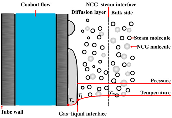
Figure 1.
Schematic diagram of NCG–steam condensation process.
Steam condensation can be categorized into two distinct modes, i.e., filmwise condensation and dropwise condensation, based on the wettability of the condensate on solid surfaces. Filmwise condensation occurs on a hydrophilic surface resulting in a continuous liquid film over the surface, impeding heat transfer. Conversely, dropwise condensation takes place on hydrophobic surfaces. This leads to discrete droplets on the surface, which enhances heat transfer by minimizing the contact area between the condensate and the surface. Numerous studies have demonstrated that dropwise condensation significantly outperforms filmwise condensation in heat transfer efficiency [13,14,15,16,17,18]. Under identical conditions, switching from filmwise to dropwise condensation can increase the heat transfer coefficient by up to three times [19,20]. Furthermore, controlling the dynamic behavior of condensate through interface structure manipulation is crucial for enhancing heat transfer performance [13,16,17,21]. Therefore, the design of various condensation surface structures and surface modification techniques to maintain long-lasting droplet condensation and regulate its dynamic behavior is one of the key scientific issues in enhancing steam condensation heat transfer in the presence of NCGs.
The presence of non-condensable gases significantly hinders condensation heat transfer. To mitigate this detrimental effect, researchers have conducted extensive experimental studies in recent years, focusing on enhancing the condensation process. Table 1 compares these studies, summarized by the type and size of the condensing surface, the employed heat transfer enhancement techniques, and the achieved enhancement effect. Ji [22] investigated the effect of altering steam operating conditions using a nozzle to inject steam vertically into a 440 mm horizontal aluminum tube. This method disrupted the boundary layer between the steam and non-condensable gas mixture, leading to a significant improvement in heat transfer. Specifically, the maximum enhancement ratio increased by at least 137%, while the average enhancement ratio rose by at least 118%. Furthermore, Ji [23] implemented a superhydrophobic surface modification on the experimental tube, conducting comparative experiments under identical conditions. The results demonstrated that under dropwise condensation, the heat transfer coefficient of the superhydrophobic tube was twice that of the bare tube. Ma et al. [18] studied the effects of a fluorocarbon coating applied to a 30 mm diameter vertical copper plate, promoting dropwise condensation. The dynamic behavior of the condensate droplets, including coalescence and detachment, created interfacial disturbances that enhanced the transfer of heat and mass between the steam and air mixture. Building upon this work, Peng et al. [24] further optimized the surface by implementing a hydrophobic–hydrophilic hybrid treatment. This modification aimed to control droplet size and distribution, leading to improved heat transfer performance. Their experimental results showed that the optimized hybrid surface achieved a 23% increase in condensation heat transfer compared with a fully dropwise condensing surface. One key challenge in steam–air condensation is the removal of condensate droplets, which can hinder heat transfer. To address this, researchers have explored surface modifications that promote droplet removal, including hybrid hydrophobic patterns. Alwazzan et al. [25] investigated the effectiveness of alternative hydrophobic and less-hydrophobic parallel straight stripes on a horizontal copper tube. The resulting wetting gradient between these adjacent regions created a force that propelled droplets across the surface, accelerating their removal. This approach significantly enhanced heat transfer compared with both complete film condensation and dropwise condensation, with improvements of 480% and 180%, respectively. Beyond the above methods, fins are another established method for enhancing heat transfer in NCG–steam condensation. Jang [26] investigated the application of annular fins in a passive condenser system. By increasing the effective heat transfer area, these fins resulted in a significant improvement in heat transfer performance, ranging from 15% to 82%. Furthermore, Fulpagare [27] explored the use of hydrophobic coatings on vertical pin fins to enhance the condensation heat transfer of nitrogen–HFE7100 mixtures. The hydrophobic coating significantly increased the heat transfer coefficient, achieving improvements between 15.6% and 31.8%. Similar to finned surfaces, foam metals possess a large surface area, making them ideal for enhancing heat transfer during steam–air condensation within tubes. Research has demonstrated that these structures can significantly improve heat transfer performance, resulting in increases ranging from 50% to 130% [28].

Table 1.
Summary of experimental studies on enhanced NCG–steam condensation heat transfer.
Building upon the benefits of enhanced heat transfer through coatings, researchers have explored the potential of optimizing surface structures for further improvements in steam–air condensation. Wen [17] fabricated a hydrophilic copper substrate with hydrophobic fluorocarbon-coated bumps. This design facilitated rapid droplet detachment and disrupted the diffusion boundary layer of non-condensable gases. Zhang [29] designed a honeycomb-structured, microporous superhydrophobic surface on a copper tube. This innovative design induced droplet jumping, significantly boosting heat transfer by a remarkable 200%. Wu [32] also investigated the influence of surface structure by incorporating gradient micro-grooves on a superhydrophobic surface. These grooves resulted in a significant 30.8% improvement in heat transfer. Kim [30] investigated the effectiveness of multilayered carbon nanotube coatings applied between a hydrophobic surface and a stainless steel substrate. Their findings demonstrated a 16% increase in the condensation heat transfer coefficient. Wu’s experiments [31] conducted on a chrome-plated stainless steel tube revealed that the air layer at the gas–liquid interface acts as significant thermal resistance. Crucially, the droplet-induced disturbance during condensation can effectively reduce the air layer resistance, leading to a 30–80% increase in heat transfer efficiency.
Non-condensable gas has a substantial impact on steam condensation, affecting heat transfer efficiency and condensation stability. Enhancing NCG–steam condensation heat transfer is a critical area of research. While numerous studies have investigated the effectiveness of surface coatings in improving condensation heat transfer on small-scale surfaces, experimental data on large-scale vertical outer tubes remains limited, particularly for materials beyond stainless steel [28,30,33,34,35]. This study addresses this gap by investigating the impact of a surface coating on the condensation heat transfer performance of both brass and stainless steel tubes. The experimental setup involved two types of tubes, i.e., coated and uncoated, each with an effective length of 1080 mm. A physical vapor deposition technique was employed to apply the same coating to both the brass and stainless steel outer tubes. By comparing the heat transfer performance of the coated and uncoated tubes, this research aims to accomplish the following:
- Quantify the contribution of the coating to the overall enhancement in air–steam condensation heat transfer.
- Analyze how the coating’s effect on condensation heat transfer varies between different base materials (brass and stainless steel).
- Examine the influence of condensate dynamics, both driven by the coating and gravity, on heat transfer enhancement.
This study contributes to the understanding of coating-enhanced condensation heat transfer in large-scale vertical tubes, providing valuable insights for designing more efficient and compact heat exchangers in various industrial applications.
2. Experiment
2.1. Test Samples and Surfaces Preparation
In this experiment, physical vapor deposition was used to modify the surface of stainless steel and brass condenser tubes with an effective length of 1080 mm and an outer diameter of 19 mm. The condenser tubes were first subjected to a cleaning process to remove surface contaminants. This involved immersing the tubes in dilute hydrochloric acid and ethanol solutions, followed by thorough rinsing with deionized water. The cleaned tubes were then placed in a cylindrical vacuum chamber and evacuated to a pressure of 10−6 Pa. Argon gas was introduced into the chamber at 1 Pa. A thin film of nickel and titanium nanoparticles was deposited on the condenser tube surfaces by high-velocity, low-temperature sputtering. In this process, a target material (nickel and titanium nanoparticles) is bombarded with ions generated by a gas discharge, causing atoms or molecules to be ejected from the target and deposited onto the tube surfaces, where they recrystallize to form a continuous metallic film. After deposition, the coated samples were heat-treated in a furnace at 300 °C for 15 min. This annealing step was followed by an oxygen plasma treatment to improve the adhesion of the coating. The surface modification process resulted in a coating thickness of approximately 3–5 μm on the condenser tubes.
2.2. Experimental Setup and Methodology
The experimental setup, illustrated in Figure 2a, consists of four primary components as follows: the condensation section, the cooling section, the data acquisition system, and the air and water supply system. The condensation section comprises a pressure vessel, three steam generators, a pressure control system, and a condenser tube. The pressure vessel, a cylindrical stainless steel container measuring 2590 mm in height and 600 mm in diameter, is insulated with thin sheets and rock wool to minimize heat loss. Three transparent, heat-resistant glass observation windows are installed on the vessel to facilitate visual monitoring of the experiment. Three 4 kW electric heaters are mounted at the bottom of the vessel, with a perforated plate positioned above to ensure uniform steam flow within the chamber. A pressure transducer measures the gas pressure within the vessel, automatically regulated by a computer-controlled power regulator based on comparisons between the transducer output and a setpoint. The condenser tube, with a vertical orientation and dimensions of 1080 mm effective length and 19 mm outer diameter, is installed in the vessel’s center. The cooling section comprises a constant temperature water bath, a pump, an electromagnetic flow meter, a heat exchanger, and connecting pipelines. The data acquisition system continuously collects and records temperature, pressure, flow rate, and condensation imagery throughout the experiment. The air and water supply system includes a vacuum pump, a water tank, a flow meter, and connecting pipelines. This study employed type T thermocouples (0.2 mm diameter) to measure various temperatures within the experimental setup. These thermocouples were rigorously calibrated in a constant-temperature water bath before the experiment. Sixteen thermocouples were installed to measure the wall temperature of the condensation tube. These thermocouples were divided into two groups of eight, each arranged along two lines parallel to the tube axis. The spacing between adjacent thermocouples on the same line was 140 mm. To ensure accurate measurement of the wall temperature, each thermocouple sensing element was carefully welded into a small groove on the wall, minimizing the influence of turbulent condensation water flow. Additionally, eight sets of thermocouples were placed 200 mm horizontally from the condenser tube, at heights of 330 mm and 750 mm. These thermocouples measured the temperature of the steam–air mixture in the main test region. The thermocouple locations are depicted in Figure 2b, which shows both a schematic and an actual photograph of the experimental setup. All thermocouple wires were routed through small holes in the pressure vessel, sealed with high-temperature adhesive, and finally secured with bolts. This arrangement allowed for comprehensive temperature monitoring throughout the condensation process.
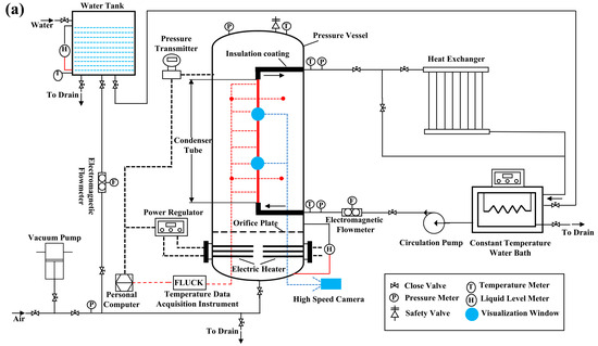
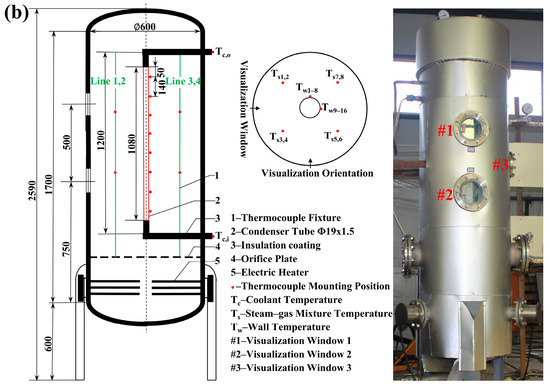
Figure 2.
Experimental setup for condensation heat transfer. (a) Schematic diagram of the experimental apparatus. (b) Schematic and physical representation of the test section. (The red line represents the condenser tube and the green line represents the spatial location in the vessel where the thermocouples that measure the bulk temperature are located.)
Before each experiment, the vessel was evacuated to a predetermined pressure, and a known volume of water was introduced. The water was then heated to the boiling point using the electric heaters, causing an increase in system pressure as steam filled the vessel. Once the target pressure was reached, the cooling water pump was activated, circulating water from a constant temperature bath through the cooling circuit. The cooling water flowed through the condenser tube, absorbing heat from the steam and transferring it to the surrounding air via a heat exchanger. To ensure steady-state conditions, the system was allowed to stabilize for a minimum of 15 min with constant cooling water flow. Stability was confirmed by monitoring and maintaining a steady system pressure, bulk temperature, and heating power. During this period, the following parameters were recorded: temperature of the vessel’s interior, temperature of the condenser wall, and inlet and outlet temperatures of the cooling water. A high-speed camera was employed to visually record the dynamic condensation process on the condenser wall through a dedicated window. To investigate the influence of various operational parameters, experiments were repeated with different pressures, air mass fractions, and cooling water inlet temperatures. The cooling water flow rate was adjusted by manipulating the pump speed while varying the cooling water inlet temperature facilitated changes in the condenser wall subcooling.
2.3. Data Reduction and Uncertainty
The experimental data were analyzed to determine the condensation HTC and the air content of the air–steam mixture. The condensation HTC was calculated using a heat balance method, which equates the total heat transfer rate from condensation to the heat absorbed by the cooling water within the condenser tube under steady-state conditions. This was expressed mathematically as follows:
where is the overall heat transfer rate (W); and are the mass flow rate (kg·s−1) and specific heat of the cooling water (J·kg−1·K−1), respectively; and and denote the inlet and outlet temperature of the cooling water (K), respectively.
Wall subcooling represents the temperature difference between the bulk air–steam mixture and the condensing tube wall, which was calculated as follows:
where denotes the average temperature of the steam–air mixture (K) and represents the average temperature of the outer wall surface of the condenser tube (K).
The average heat transfer coefficient was then determined by dividing by and , as given by
where represents the outer surface area of the condenser tube (), denotes its external diameter (m), and L represents its length (m).
The condensation heat flux q was evaluated by dividing by , as given by
This study investigated the impact of air content on the heat transfer coefficient during steam condensation. To analyze this phenomenon, it was necessary to determine the mass fraction of air in the air–steam mixture under different operating conditions. Assuming the steam is saturated, the mixture can be treated as an ideal gas. Applying the ideal gas law, the total pressure of the mixture is equal to the sum of the partial pressures of its components, as given by
where denotes the total pressure of the steam–air mixture (MPa), represents the partial pressure of steam (MPa), and represents the partial pressure of air (MPa).
The steam pressure was determined based on the bulk temperature, and the relationship was expressed as follows:
Since the steam and air within the container share the same volume and temperature, an expression for the mass fraction of air in the mixture using the ideal gas law was derived as follows:
where and represent the mass of air and steam (kg), respectively; and denote the number of moles of steam and air (mol), respectively; and and denote the molar masses of air and steam (kg·mol−1), respectively.
To ensure the reliability of the experimental results, an uncertainty analysis of the measured and derived quantities was conducted. This analysis accounted for the inherent uncertainties in experimental measurements. By analyzing the uncertainty associated with each measured parameter, the overall uncertainty in the final results was estimated. Table 2 presents the uncertainties related to each parameter in this experiment. The uncertainties in the average condensation heat transfer coefficient and the heat flux were calculated using Equations (8) and (9), respectively. The uncertainties in the air mass fraction and the average condensation HTC were within 2.3% and 1.6%, respectively.

Table 2.
Accuracy analysis of experimentally measured parameters.
3. Results and Discussion
This study investigated the heat transfer characteristics of steam condensation on the following four different tube materials: uncoated brass, uncoated stainless steel, coated brass, and coated stainless steel. Each tube had an effective length of 1080 mm. The experimental setup allowed us to vary the conditions, as summarized in Table 3. The heat transfer performance was evaluated by measuring the heat flux and condensation HTC under these varied conditions. Furthermore, the dynamic behavior of the condensate was visually observed and analyzed. This visual analysis provided insights into how condensate dynamics influence heat transfer enhancement.

Table 3.
Operating conditions for the experiment.
3.1. Comparative Analysis of Surface Condensation Heat Transfer on Stainless Steel Tubes with and without a Coating
Figure 3 and Figure 4 present the variation in condensation HTC and heat flux with wall subcooling for the bare and coated stainless steel tubes at various NCG concentrations. Figure 3 reveals a significant enhancement in the condensation HTC as the NCG concentration decreases. This enhancement is attributed to a reduction in the resistance to heat and mass transfer within the gas diffusion layer, as well as an increase in the partial pressure of the steam. For each NCG concentration, the HTC exhibits a consistent trend concerning subcooling. Initially, the HTC increases with increasing subcooling. However, at higher subcooling levels, the HTC begins to decrease. The coating on the tube surface leads to a substantial enhancement in the peak condensation HTC compared with the bare tube. At NCG concentrations of 0.4, 0.3, 0.15, and 0.08, the peak HTC for the coated tube is 22.2%, 11.9%, 4.2%, and 19.6% higher than that of the bare tube, respectively. However, at NCG concentrations of 0.15 and 0.08, the decrease in HTC with increasing subcooling is more pronounced for the coated tube, resulting in a crossover point between the curves for the coated and bare tubes. This behavior can be explained by reducing gas diffusion layer resistance at lower NCG concentrations. At higher subcooling levels, the increased condensation rate leads to surface flooding on the coated tube, reducing the condensate disturbance of the gas diffusion layer and resulting in a smaller decrease in gas diffusion layer thermal resistance compared with the added thermal resistance of the coating itself.
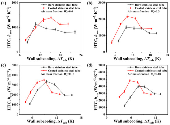
Figure 3.
Heat transfer coefficient –subcooling curves for bare and coated stainless steel tubes at the air concentrations of = 0.4 (a), = 0.3 (b), = 0.15 (c), and = 0.08 (d).
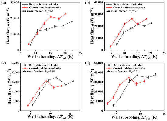
Figure 4.
Heat flux q–subcooling curves for bare and coated stainless steel tubes at the air concentrations of = 0.4 (a), = 0.3 (b), = 0.15 (c), and = 0.08 (d).
Figure 4 presents the variation in heat flux with subcooling for both the bare and coated stainless steel tubes under different NCG concentrations. At NCG concentrations of 0.4 and 0.3, the coated tube exhibits consistently higher heat flux compared with the bare tube. Specifically, the maximum heat flux of the coated tube is enhanced by 26.4% and 15.7% at NCG concentrations of 0.4 and 0.3, respectively, as shown in Figure 4a,b. However, a crossover phenomenon in the heat flux curves is observed at lower NCG concentrations (0.15 and 0.08). The maximum heat flux density of the coated tube is 10.5% and 8.0% lower than that of the bare tube at NCG concentrations of 0.15 and 0.08, respectively (Figure 4c,d). These findings indicate that the coated stainless steel tube significantly enhances condensation heat transfer efficiency at high NCG concentrations. However, the enhancement effect diminishes at low NCG concentrations.
To further illustrate the experimental results, Figure 5 presents the dynamic behavior of the condensate on the outer surface of the tube under different operating conditions. Figure 5a shows the stable film condensation on the outer surface of the bare tube at an NCG concentration of 0.3 and subcooling of approximately 14 K. The condensate film flows along the tube wall under the influence of gravity, with a flow velocity of approximately 0.5 m per second. This is primarily attributed to the large size and vertical orientation of the condensing tube, which provides an acceleration path for the flowing film, resulting in a gradual increase in the film flow rate along the flow direction. Figure 5b depicts droplet condensation on the coated tube surface under the same NCG concentration and subcooling. The condensate grows, coalesces, and detaches in the form of droplets. Dense droplets frequently coalesce during growth, accompanied by fluctuations caused by bouncing coalescence. Droplets detach when their weight exceeds the surface tension. This droplet detachment behavior enhances the condensation heat transfer. On one hand, it clears droplets adhered to the tube wall, providing a larger vapor contact surface for subsequent condensation; on the other hand, it disturbs the gas-phase diffusion layer, promoting mass transfer. In steam condensation with NCG, the thermal resistance of the gas-phase diffusion layer is the primary factor controlling heat transfer. Compared with the flow of condensate film on the bare tube surface, the frequent coalescence and detachment of droplets on the coated tube surface intensify the disturbance frequency and extent of the gas-phase diffusion layer, significantly reducing the diffusion layer thermal resistance and thereby enhancing the heat and mass transfer efficiency. Figure 5c displays the coexistence of film and droplet condensation on the coated tube surface at an NCG concentration of 0.08 and a degree of subcooling of approximately 10 K. The majority of the surface is submerged in condensate forming a film, while a small number of droplets coalesce, and some droplets are observed to remain pinned to the tube wall for extended periods.
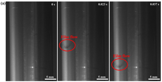
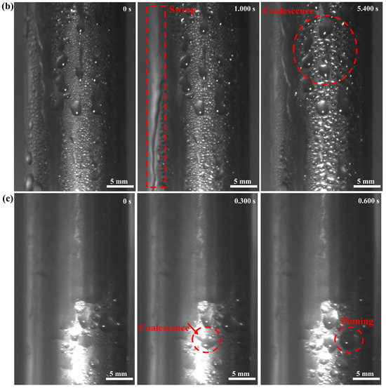
Figure 5.
Dynamic behavior of condensate on the surface of bare and coated stainless steel tubes. (a) Bare tube, NCG = 0.3, = ~14 K, (b) coated tube, NCG = 0.3, = ~14 K, and (c) coated tube, NCG = 0.08, = ~10 K.
3.2. Comparative Analysis of Surface Condensation Heat Transfer on Brass Tubes with and without a Coating
To investigate the influence of the same surface modification to different base materials on the heat transfer performance of air-containing steam condensation, we applied the modification to brass tubes. Figure 6 and Figure 7 show the variation in the condensation HTC and heat flux of a coated brass tube and a bare brass tube concerning the subcooling under different non-condensable gas (NCG) content (0.4, 0.3, 0.15, and 0.08, respectively). The experimental results demonstrate that, regardless of the NCG content, the condensation HTC and heat flux of the coated brass tube are significantly higher than those of the bare brass tube, exhibiting an increasing and then decreasing trend with increasing subcooling. Specifically, under the same NCG content, the maximum condensation HTCs of the coated brass tube are 58.9%, 53.5%, 68.0%, and 70.7% higher than those of the bare brass tube (NCG contents of 0.4, 0.3, 0.15, and 0.08, respectively). Similarly, the heat flux of the coated brass tube is also higher than that of the bare brass tube, with maximum increases of 57.7%, 15.3%, 31.6%, and 33.0% (NCG content of 0.4, 0.3, 0.15, and 0.08, respectively). These findings indicate that the same type of surface modification applied to brass tubes, as was used to stainless steel tubes, can significantly enhance the heat transfer performance.
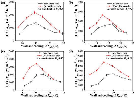
Figure 6.
Heat transfer coefficient –wall subcooling curves for bare and coated brass tubes at the air concentrations of = 0.4 (a), = 0.3 (b), = 0.15 (c), and = 0.08 (d).
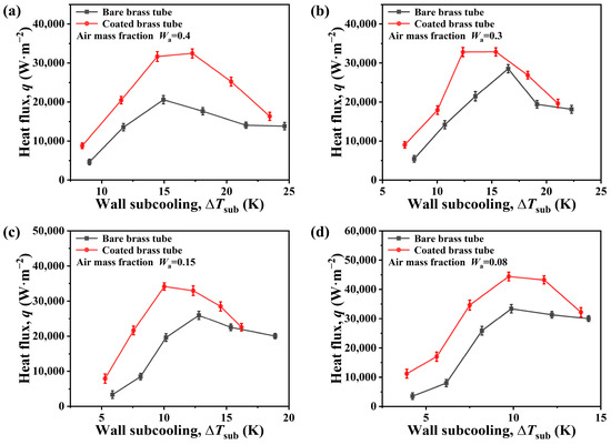
Figure 7.
Heat flux q–wall subcooling curves for bare and coated brass tubes at the air concentrations of = 0.4 (a), = 0.3 (b), = 0.15 (c), and = 0.08 (d).
The condensation pattern on both tubes was consistently dropwise under different NCG content and subcooling conditions. Figure 8 illustrates the dynamic process of condensate on both tube surfaces when the NCG content was 0.3 and the subcooling was approximately 12 K. On the bare brass tube, condensate droplets exhibit a relatively slow growth rate and infrequent coalescence, and they were widely stapled on the surface. However, two condensate detachments were observed within 3 s. These detachments occurred at a velocity of approximately 0.5 m/s, following repetitive and linear paths and resulting in a limited scouring area. In contrast, the condensate on the coated brass tube displayed a significantly more dynamic behavior. The droplets grew rapidly and were densely distributed, frequently bouncing and coalescing into larger liquid masses. Detachment occurred more frequently, with three events observed within 2 s. This resulted in a wider scouring area and meandering detachment paths, which provided a larger surface area for subsequent condensation. The enhanced disturbance frequency observed on the coated brass tube is directly linked to the heat transfer efficiency. In steam condensation containing NCG, the thermal resistance of the gas-phase diffusion layer is a critical factor. The frequent coalescence and detachment of droplets on the coated brass tube effectively increased the frequency and extent of disturbances within this diffusion layer. This, in turn, promoted mixing within the layer, leading to a reduction in the gas-phase boundary layer thickness. The reduced thickness ultimately lowered the thermal resistance of the diffusion layer, enhancing heat transfer efficiency.
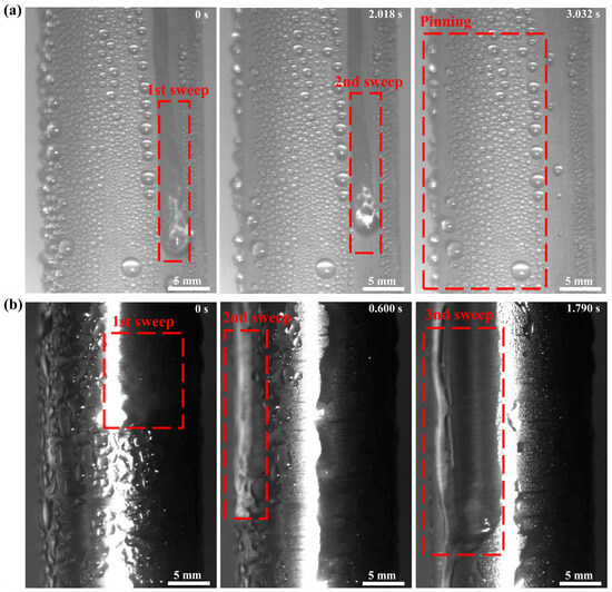
Figure 8.
Dynamic behavior of condensate on the surface of bare and coated brass tubes at NCG = 0.3, = ~12 K for the (a) bare tube and (b) coated tube.
4. Conclusions
The presence of non-condensable gas during steam condensation significantly affects heat transfer efficiency and the stability of the condensation process. This study investigated the enhanced condensation heat transfer performance of large-scale coated tubes in an air-containing environment through a visualization experiment. Four different types of condensation tubes were selected, including a coated stainless steel tube, a coated brass tube, a bare stainless steel tube, and a bare brass tube, all with an outer diameter of 19 mm and an effective length of 1080 mm. The experimental results show that because of the vertical orientation and substantial length of the tubes, the condensate flow velocity on the surface of the bare stainless steel and brass tubes reached 0.5 m/s, leading to increased disturbance of the diffusion layer during condensate detachment. Visualization images revealed a stable filmwise condensation on the surface of the bare stainless steel tube. In contrast, the coated stainless steel tube exhibited dropwise condensation or a combined state of dropwise and filmwise condensation. The droplets on the bare brass tube exhibited extensive pinning, resulting in a limited condensate detachment and sweeping area. However, the condensate on the coated brass tube demonstrated more frequent disturbance, faster droplet growth, a denser distribution, and a wider condensate detachment and sweeping area. Compared to the bare stainless steel tube, the condensation heat transfer coefficient of the coated stainless steel tube showed an increase across different air concentrations, with maximum improvements of 22.2%, 11.9%, 4.2%, and 19.6%. Similarly, compared with the bare brass tube, the condensation heat transfer coefficient of the coated brass tube exhibited substantial improvements across various air concentrations, with maximum values reaching 58.9%, 53.5%, 68.0%, and 70.7%, and the heat flux density reached maximum values of 57.7%, 15.3%, 31.6%, and 33.0%. This indicates that the coated brass tube more effectively promotes condensate detachment and disturbance, thereby enhancing heat transfer efficiency.
Author Contributions
Conceptualization, Z.C. and K.Z.; Methodology, Z.C. and K.Z.; Investigation, Z.C. and K.Z.; Resources, N.W.; Data curation, Z.C. and K.Z.; Writing—original draft, Z.C.; Writing—review & editing, Z.C.; Supervision, N.W. All authors have read and agreed to the published version of the manuscript.
Funding
This research received no external funding.
Data Availability Statement
The data presented in this study are available on request from the corresponding author due to privacy reasons.
Conflicts of Interest
The authors declare no conflict of interest.
Nomenclature
| condensing surface area, | |
| specific heat capacity of coolant, J/(kg·K) | |
| h | heat transfer coefficient, |
| L | condensate tube length, mm |
| mass flow rate of coolant, kg/s | |
| M | molar mass, kg/mol |
| P | pressure, MPa |
| q | heat flux, W |
| Q | overall heat transfer rate, W |
| T | temperature, K |
| average temperature, K | |
| U | uncertainty |
| W | mass fraction |
| Subscripts | |
| a | air |
| ave | average |
| c | coolant |
| in | coolant inlet |
| out | coolant out |
| s | saturated steam |
| sub | subcooling |
| w | condenser tube wall |
| bulk | |
| Greek symbols | |
| difference | |
| Abbreviations | |
| HTC | heat transfer coefficient |
| NCG | non-condensable gas |
References
- Bao, J.; Lin, Y.; Zhang, R.; Zhang, N.; He, G. Strengthening power generation efficiency utilizing liquefied natural gas cold energy by a novel two-stage condensation Rankine cycle (TCRC) system. Energy Convers. Manag. 2017, 143, 312–325. [Google Scholar] [CrossRef]
- Galuppo, F.; Reiche, T.; Lemort, V.; Dufour, P.; Nadri, M. Organic Rankine Cycle based waste heat recovery modeling and control of the low pressure side using direct condensation and dedicated fans. Energy 2021, 216, 119074. [Google Scholar] [CrossRef]
- Lukic, N.; Diezel, L.L.; Fröba, A.P.; Leipertz, A. Economical aspects of the improvement of a mechanical vapour compression desalination plant by dropwise condensation. Desalination 2010, 264, 173–178. [Google Scholar] [CrossRef]
- Ardy, H.; Nurimam, A.; Hamdani, M.; Abednego, T.H.; Helmy, R.K.; Bangun, D.A.; Setiawan, A.R.; Wibowo, A.; Sumboja, A. Failure analysis of admiralty brass tubes in a surface condenser: A case study at the petrochemical industry. Mater. High Temp. 2021, 38, 177–185. [Google Scholar] [CrossRef]
- Yadav, M.K.; Khandekar, S.; Sharma, P.K. An integrated approach to steam condensation studies inside reactor containments: A review. Nucl. Eng. Des. 2016, 300, 181–209. [Google Scholar] [CrossRef]
- Lee, J.Y.; Jeong, J.J.; Yun, B. Modifications of the turbulent diffusion layer model for the condensation heat transfer under the presence of noncondensable gases. Ann. Nucl. Energy 2020, 137, 107060. [Google Scholar] [CrossRef]
- Peterson, P.F.; Schrock, V.E.; Kageyama, T. Diffusion layer theory for turbulent vapor condensation with noncondensable gases. J. Heat Transf. 1993, 115, 998–1003. [Google Scholar] [CrossRef]
- Othmer, D.F. The condensation of steam. Ind. Eng. Chem. 1929, 21, 576–583. [Google Scholar] [CrossRef]
- Huang, J.; Zhang, J.X.; Wang, L. Review of vapor condensation heat and mass transfer in the presence of non-condensable gas. Appl. Therm. Eng. 2015, 89, 469–484. [Google Scholar] [CrossRef]
- Yang, J.H.; Ahn, T.H.; Bae, H.; Park, H.S. Investigation of condensation with non-condensable gas in natural circulation loop for passive safety system. Nucl. Eng. Technol. 2023, 55, 1125–1139. [Google Scholar] [CrossRef]
- Arsenyeva, O.; Klemes, J.J.; Tovazhnyanskyy, L.; Klochok, E.; Kapustenko, P. Estimating parameters of plate heat exchanger for condensation of steam from mixture with air as a component of heat exchanger network. Energy 2023, 283, 128482. [Google Scholar] [CrossRef]
- Fu, P.F.; Zhou, Y.; Yang, X.P.; Yan, J.J.; Liu, J.P. Experimental study on the effect of non-condensable gas dissolved in sub-cooled water on steam jet condensation in a rectangular channel. Int. J. Heat Mass Transf. 2019, 134, 668–679. [Google Scholar] [CrossRef]
- Lv, F.; Lin, S.; Nie, H.; Dong, Z.; Zhao, F.; Cheng, D.; Dong, Z.; Gulfam, R. Droplet dynamics and heat transfer enhancement via dropwise condensation on helically-finned hydrophobic tube. Int. Commun. Heat Mass Transf. 2022, 135, 106153. [Google Scholar] [CrossRef]
- Cha, H.; Vahabi, H.; Wu, A.; Chavan, S.; Kim, M.K.; Sett, S.; Miljkovic, N. Dropwise condensation on solid hydrophilic surfaces. Sci. Adv. 2020, 6, eaax0746. [Google Scholar] [CrossRef] [PubMed]
- Orejon, D.; Shardt, O.; Gunda, N.S.K.; Ikuta, T.; Takahashi, K.; Takata, Y.; Mitra, S.K. Simultaneous dropwise and filmwise condensation on hydrophilic microstructured surfaces. Int. J. Heat Mass Transf. 2017, 114, 187–197. [Google Scholar] [CrossRef]
- Zhong, L.; Yansong, C.; Shaobo, H.; Guangzhao, Y.; Xuehu, M. Droplet regulation and dropwise condensation heat transfer enhancement on hydrophobic-superhydrophobic hybrid surfaces. Heat Transf. Eng. 2017, 39, 1540–1551. [Google Scholar]
- Wen, R.F.; Zhou, X.D.; Peng, B.L.; Lan, Z.; Yang, R.G.; Ma, X.H. Falling-droplet-enhanced filmwise condensation in the presence of non-condensable gas. Int. J. Heat Mass Transf. 2019, 140, 173–186. [Google Scholar] [CrossRef]
- Ma, X.H.; Zhou, X.D.; Lan, Z.; Li, Y.M.; Zhang, Y. Condensation heat transfer enhancement in the presence of non-condensable gas using the interfacial effect of dropwise condensation. Int. J. Heat Mass Transf. 2008, 51, 1728–1737. [Google Scholar] [CrossRef]
- Ma, X.; Chen, J.; Xu, D.; Lin, J.; Ren, C.; Long, Z. Influence of processing conditions of polymer film on dropwise condensation heat transfer. Int. J. Heat Mass Transf. 2002, 45, 3405–3411. [Google Scholar] [CrossRef]
- Preston, D.J.; Wang, E.N. Jumping droplets push the boundaries of condensation heat transfer. Joule 2018, 2, 205–207. [Google Scholar] [CrossRef]
- Alwazzan, M.; Egab, K.; Peng, B.; Khan, J.; Li, C. Condensation on hybrid-patterned copper tubes (II): Visualization study of droplet dynamics. Int. J. Heat Mass Transf. 2017, 112, 950–958. [Google Scholar] [CrossRef]
- Ji, D.Y.; Kim, D.; Lee, K.Y. Enhancement of condensation heat transfer in the presence of non-condensable gas using steam jet method. Int. J. Heat Mass Transf. 2019, 130, 603–612. [Google Scholar] [CrossRef]
- Ji, D.-Y.; Lee, J.-W.; Kim, D.; Hwang, W.; Lee, K.-Y. Effective reduction of non-condensable gas effects on condensation heat transfer: Surface modification and steam jet injection. Appl. Therm. Eng. 2020, 174, 115264. [Google Scholar] [CrossRef]
- Peng, B.; Ma, X.; Lan, Z.; Xu, W.; Wen, R. Experimental investigation on steam condensation heat transfer enhancement with vertically patterned hydrophobic–hydrophilic hybrid surfaces. Int. J. Heat Mass Transf. 2015, 83, 27–38. [Google Scholar] [CrossRef]
- Alwazzan, M.; Egab, K.; Peng, B.; Khan, J.; Li, C. Condensation on hybrid-patterned copper tubes (I): Characterization of condensation heat transfer. Int. J. Heat Mass Transf. 2017, 112, 991–1004. [Google Scholar] [CrossRef]
- Jang, Y.-J.; Choi, D.-J.; Kim, S.; Hyun, M.-T.; Lee, Y.-G. Enhancement of condensation heat transfer rate of the air-steam mixture on a passive condenser system using annular fins. Energies 2017, 10, 1777. [Google Scholar] [CrossRef]
- Fulpagare, Y.; Wu, Y.-J.; Chang, J.-Y.; Wang, C.-C. Effect of Non-Condensable gas on condensing performance of HFE7100 With/Without hydrophobic coating. Appl. Therm. Eng. 2022, 213, 118807. [Google Scholar] [CrossRef]
- Li, L. Experimental study on enhancement condensation heat transfer in tube by foam metal in presence of non-condensable gas. J. Phys. Conf. Ser. 2024, 2671, 012012. [Google Scholar] [CrossRef]
- Zhang, T.Y.; Mou, L.W.; Zhang, J.Y.; Fan, L.W.; Li, J.Q. A visualized study of enhanced steam condensation heat transfer on a honeycomb-like microporous superhydrophobic surface in the presence of a non-condensable gas. Int. J. Heat Mass Transf. 2020, 150, 119352. [Google Scholar] [CrossRef]
- Kim, T.; Shin, D.; Lee, J.; Kim, S.J. Effect of layer-by-layer assembled carbon nanotube coatings on dropwise condensation heat transfer associated with non-condensable gas effect. Int. J. Heat Mass Transf. 2021, 175, 121345. [Google Scholar] [CrossRef]
- Wu, D.; Gui, M.Y.; Cheng, J.; Fan, G.M.; Wang, J.J. Condensation enhancement experiment investigation of pure steam and steam-air mixture over the chrome-plated tube with different plating thickness. Prog. Nucl. Energy 2023, 166, 104971. [Google Scholar] [CrossRef]
- Wu, S.; Gao, S.; Wang, H.; Deng, Z. Dropwise condensation heat transfer on vertical superhydrophobic surfaces with gradient microgrooves in humid air. Int. J. Heat Mass Transf. 2023, 201, 123583. [Google Scholar] [CrossRef]
- Chang, W.; Luo, K.; Wang, P.; Li, C. Sustaining dropwise condensation on nickel-plated copper surfaces with As-grown graphene coatings. Appl. Therm. Eng. 2022, 209, 118319. [Google Scholar] [CrossRef]
- Khan, S.A.; Tahir, F.; Baloch, A.A.B.; Koc, M. Review of micro–nanoscale surface coatings application for sustaining dropwise condensation. Coatings 2019, 9, 117. [Google Scholar] [CrossRef]
- Nguyen, D.H.; Ahn, H.S. A comprehensive review on micro/nanoscale surface modification techniques for heat transfer enhancement in heat exchanger. Int. J. Heat Mass Transf. 2021, 178, 121601. [Google Scholar] [CrossRef]
Disclaimer/Publisher’s Note: The statements, opinions and data contained in all publications are solely those of the individual author(s) and contributor(s) and not of MDPI and/or the editor(s). MDPI and/or the editor(s) disclaim responsibility for any injury to people or property resulting from any ideas, methods, instructions or products referred to in the content. |
© 2024 by the authors. Licensee MDPI, Basel, Switzerland. This article is an open access article distributed under the terms and conditions of the Creative Commons Attribution (CC BY) license (https://creativecommons.org/licenses/by/4.0/).