Abstract
Regulatory boards are promoting closed distribution systems (CDSs), which are different from traditional public-access networks, that can be owned and managed by energy communities (ECs). The inclusion of local renewable energy potential and an adequate schedule of storage devices in a CDS allow cooperation among the EC’s members in order to reduce operational expenditure (OPEX), providing internally competitive electricity prices with respect to those provided by publicly regulated networks and electricity markets. The CDS operators can assume a new role as the centralized energy dispatchers of generation and storage assets in order to maximize the profits of the members of the EC. This paper proposes an innovative optimal active and reactive power dispatch model for maximum community welfare conditions. A key difference between this proposal and existing social-welfare-based dispatches on public-access networks is the exclusion of the profit of the external wholesale electricity market. The focus of the proposed method is to maximize the welfare of all community members. A remuneration framework based on a collective EC with a single frontier is adopted, considering agreements between members based on locational marginal pricing (CDS-LMP). Results from an illustrative case study show a reduction of 50% in the EC’s OPEX with a payback time of 6 years for investments in CDSs, renewable sources, and storage.
1. Introduction
Many regulatory boards are adopting different remuneration schemes for users grouped into an energy community (EC) and connected to public grids using multiple metering frontiers or points of delivery (PoD). The literature on transactive energy local markets is vast, and a complete review of the state of the art on this topic can be found in [1].
In some countries, such as Colombia, the regulatory board (Resolution 901-501-2024, Art. 11) [2] allows that an EC can be constituted with its own closed distribution system (CDS) with a single frontier or PoD with the public grid, as shown in Figure 1. In this case, EC members adopt a private agreement with the conditions for the dispatch and remuneration of the produced energy, as well as the investment in distribution and generation assets. The regulator also establishes a remuneration scheme for the energy exported to the grid.
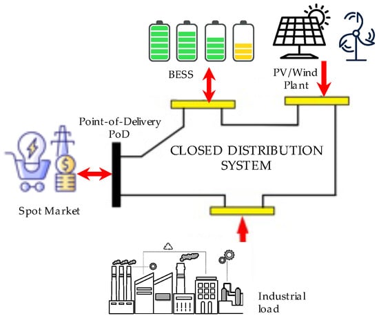
Figure 1.
Energy community whose CDS is connected to the public grid with a single metering frontier or point of delivery.
The idea of a CDS for the exclusive use of an EC, different from the traditional public network, is not a new concept. Since 2013, the Council of European Energy Regulators has been promoting the unbundling requirements for system operators (SOs) in order to improve economic efficiency [3]. According to the European Directive 2019/944/CE [4] (Art. 38), industrial, commercial, and residential ECs, integrated within a specific confined area, can establish and manage their own CDSs [5]. The CDS is admitted in several European countries, for instance, Germany [6], Spain [7], Portugal [8], Italy [9,10], and Estonia [11].
European regulators argue that CDSs will play a relevant role in industrial sectors at the risk of relocation due to high energy costs and network access tariffs, with the consequent economic advantages for the whole economy [3]. A CDS is for the exclusive use of EC members and cannot be considered a public, open-access network. As a result, the CDS is not subject to remuneration via regulated tariffs for the use of the network. The EC is responsible for the CDS’s capital expenditures and operating expenses. The CDS will allow a reduction in costs and the economics of electrical energy for medium and large industries, improving their competitiveness at a time when it is key to the maintenance of the existing industry and reindustrialization [7].
Harnessing local renewable energy potential and the adequate management of energy storage devices connected to a CDS allows cooperation among the EC’s members in order to reduce operational expenditure (OPEX), with internally competitive electricity prices with respect to those provided by publicly regulated networks and electricity markets. The Supervisory Control and Data Acquisition and Energy Management System (SCADA/EMS) of the CDS must be handled by a new entity: the CDS operator (CDS-O), who must assume a new role as a centralized energy dispatcher of generation and storage assets in order to maximize the EC’s profits. This implies a new paradigm that requires the development of new EMS functions, such as energy dispatch models for specific CDS infrastructure, different from those applied by traditional SOs [12].
The CDS-O seeks to operate the generation assets by maximizing profits from energy exchange with the electricity market as well as minimizing the operation cost. The CDS-O has more centralized control, allowing the precise management of the system, including optimizing active and reactive power generation resources, load balancing, and voltage regulation. Thus, the power dispatch of several loads, energy storage devices, and generators can be performed according to a remuneration scheme that seeks overall positive profits for all EC members.
The literature on optimal power dispatch for microgrids and distributed generators connected to traditional distribution systems is also extensive. A comprehensive review of system operator dispatch models for from-the-meter arrangements can be found in [13,14]. There is also a lot of research on new models for behind-the-meter power dispatch optimization, mainly about small-sized micro-grids in residential energy communities. Table 1 shows the most-cited contributions on microgrid power dispatch models according to Scopus over the last 10 years.

Table 1.
State of the art on microgrid optimal power dispatch models.
Most of the publications listed in Table 1 do not include CDS as an option to improve the EC’s power system performance. The literature devoted to dispatch models considering CDSs is scarce. In [25], a simple real-time pricing model is proposed for the sizing and the active power dispatch of an EC with multiple commercial frontiers. This model is formulated as a bi-level optimization problem where the profit of the CDS operator and the profit due to energy exchange are maximized separately.
However, the use of a CDS with multiple commercial frontiers may be questionable in the light of existing regulations. Added to this, ref. [25] aims to maximize EC’s profits, disregarding the mathematical representation of active and reactive power flows in the CDS. The dispatch of active (P) and reactive (Q) power, considering an explicit network model, is crucial to ensuring adequate voltage support. The CDS-O must develop adequate pricing and power dispatch methodologies in order to reach economic efficiency.
To fill the research gap, this paper proposes an innovative optimal active and reactive power dispatch model for energy communities with a detailed representation of a closed distribution system connected to an external public grid through a single frontier. Different actors, such as local electricity producers with storage devices and industrial, commercial, and residential loads with demand response, are connected to a CDS. The economic surplus of the CDS is also included as a component of the community welfare objective to be maximized. A key difference between this proposal and existing social-welfare-based dispatches is that the surplus of external generators in the wholesale market is not considered. A remuneration framework based on distribution locational marginal pricing (CDS-LMP) is applied according to the ongoing smart grid paradigm [26,27,28]. Battery scheduling and generation/demand dispatch are determined for the maximum community welfare condition, considering the reactive power capability of energy producers. The proposed model has been applied to an illustrative case study.
2. Conceptual Framework
According to the Colombian energy community policy framework ([2], Art. 11), EC members, producers, and consumers can be aggregated behind a single PoD, as shown in Figure 1. The energy community commercially aggregates different kinds of energy users: industrial, commercial, and residential consumers; traditional energy producers (electricity and steam); renewable producers (PV and wind); and energy storage systems (batteries and reversible hydro-pumping).
The EC members adopt a private agreement where the CDS operator defines the storage scheduling pattern according to the expected output of renewable plants, load consumption, and wholesale spot prices. The EC exchanges energy (purchase and sell) at spot market hourly prices, paying the corresponding tariffs for use on the public network.
The energy pricing model applied to the members of the EC, as shown in Figure 2, is based on the smart grid paradigm [26,27,28]. Two stages are considered. First, the active and reactive power dispatch of the EC is carried out by the CDS-O in order to obtain active energy locational marginal prices (CDS-LMPs) by means of the optimization model stated in Section 3. In a second stage, the investment attractiveness of the project is evaluated considering the economic results of the first stage.

Figure 2.
General framework for active and reactive power dispatch with marginal pricing signals.
The optimization process corresponds to an active and reactive power dispatch, seeking the maximum community welfare condition. Locational marginal price signals for active powers (CDS-LMPs) are sent to all agents connected to the CDS. This means that the price set in nodes 2, 3, and 4 in Figure 1 may be different for each node, depending on the incurred losses. Loads have been modeled with demand response capability, with the ability to change their consumption level depending on varying hourly CDS-LMPs. With the CDS-LMPs and energy flows, the operational income and expenditures (OPEX) of all energy community members are determined. Finally, according to the capital expenditure requirements of renewable generators, storage devices, and CDSs, financial indicators such as the project payback time, net present value, benefit/cost ratio, and internal rate of return are assessed.
3. Methodology
In the section we present the proposed methodology for the optimal power dispatch for energy community welfare by considering closed distribution systems and renewable resources. To improve the understanding of the mathematical formulation, a list of symbols and acronyms is included in the Nomenclature section.
The energy community’s best power dispatch solution is achieved in the search for economic efficiency. Economic efficiency is procured by maximizing the maximum welfare for all the community members as objectives: electricity producers, loads, storage devices, and the EC’s network operator. The optimization model has different kinds of restrictions: nodal power balance at each hour, energy flow capacity constraints, reactive power capability of generators and battery energy storage systems (BESSs), storage scheduling constraints, and demand response facing changing electricity prices.
The general structure of the proposed power dispatch model is giving as follows:
- max CW [Maximum community welfare];
- s.t.;
- (1) CDS Model: The AC Power Balance;
- (2) Capacity constraints;
- (3) Power capability curves of generators and BESSs;
- (4) BESS model;
- (5) Load demand response model.
3.1. Optimization Model Objective
Welfare economics is a concept that reflects the well-being of society; in this case, the concept is applied only to the EC members. Community welfare () is defined in this paper as the sum of all actors’ economic surpluses [29]:
where is the producer economic surplus in $/T, is the demand economic surplus in $/T, is the storage economic surplus in $/T, and is the CDS economic surplus in $/T. Term T is the time span, typically, a year, a week, 24 h (one day), etc. However, these surpluses, as well as the economic interchange with the spot market, should be extrapolated on an annual basis to determine if the savings obtained for the optimal power dispatch procedure are enough to recover the capital costs of the EC assets.
In traditional power dispatch social-welfare models, such as [30], the term is usually related to the surplus of the traditional SO when marginal prices are applied to the entire public distribution grid. Marginal pricing is important in this context since it allows for a fair allocation of losses and congestion [29].
In the case of a CDS, the profit from is exclusive to the CDS owner. It is important to recall that, according to [31], marginal loss pricing causes a profit that can be used to partially cover various fixed costs. It must be noted that the profits of the spot market are not included in the objective since they do not belong to the community.
3.1.1. Producer Surplus
The energy community is able to manage its own generation facilities. Entry is the surplus of all generators (renewable or not) due to energy sold at a given CDS-LMP over the period T. The producer surplus () is defined as the difference between the producer revenues for energy sold and the producer costs () [29]:
where T denotes the time span, for instance, 24 h (a day);
n denotes the last node number of the CDS;
k denotes a CDS node number, ;
corresponds to the single frontier node (connection with the public grid);
t denotes a given hour;
is the CDS-LMP at node k hour t in $/MWh;
is the average active power produced at node k hour t in MW, ;
and the production cost is given by
where is the total production cost at node k, is the power output of the producer in MW, is the linear marginal coefficient expressed in $/MWh, and is the quadratic marginal coefficient in $/MW2·h. Coefficients and are specific for each producer, reflecting the operational expenditure of the technology used to generate electric energy. It is well known that renewable-based generation, such as PV, has a low operational expenditure. Note that generation at node 1 is not included in the generation surplus associated with a CDS.
3.1.2. Consumer Surplus
The introduction of smart meters (SMs) and advanced metering infrastructure (AMI) may allow demand response that originates from locational marginal prices to be calculated by the SO [28,30]. The SM is a device that includes sophisticated measurement and calculation hardware, software, calibration, and communication capabilities. For interoperability within a smart grid infrastructure, SMs are designed to perform functions and store and communicate data according to certain standards. This means that CDS-LMPs () can be charged to all consumers connected at a given node k on a day-ahead or real-time basis [26,27]. Under this paradigm, higher prices lead to lower power consumption. Lower prices lead to higher power consumption.
The demand curve (Figure 3) follows the following linear function [29]:
where is the CDS-LMP at node, is the highest price that the demand is willing to pay in $/MWh, is the slope of the demand curve in $/MW2·h, and is the power consumed at node k in MW. The slope is specific to each node k.
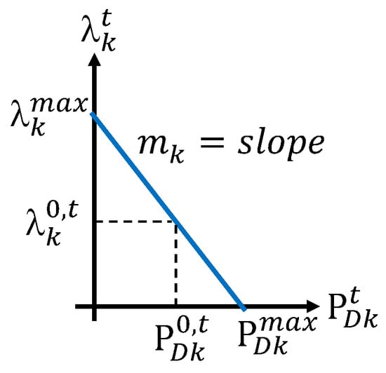
Figure 3.
Demand curve function.
According to [29], the utility of demands connected at node k is defined as
The consumer surplus is defined as the difference between the utility () and the payment for the purchased power [29]:
The total demand utility is given by = [$/day].
3.1.3. BESS Surplus
The surplus of BESS is defined as the arbitrage, that is, the difference between the power sold at time t when the battery is discharging and the power purchased at time t when the battery is charging along a span time T:
The daily energy purchased by the BESS is = when . On the other hand, the daily energy sold by the BESS is = when .
3.1.4. CDS Surplus
The CDS is owned by the EC. Unlike networks operated by traditional SOs, each node in the CDS has a different CDS-LMP. As the CDS is not linear, losses and congestion have an impact on CDS-LMPs, depending on the amounts of active and reactive power injections by each community member. Therefore, the operator that manages the CDS has a surplus (), defined as [29]:
where is the daily energy bought by demands and is the daily energy sold by the generators.
The introduction of constitutes a contribution to this paper in the context of the new paradigm based on CDSs exposed to marginal prices. The marginal surplus shown in Equation (8) was extensively treated by Schweppe in [29] for transmission networks, and, in our opinion, this concept can be applied to special networks such as the CDS in order to send appropriate cost-reflective signals for the community members.
3.2. Optimization Model Constraints
Five sets of constraints are considered in the proposed model: (1) The network model for the CDS, (2) Capacity constraints, (3) Reactive power capability curves, (4) BESS model, and (5) Demand response model.
3.2.1. The Network Model for the CDS
The n-node CDS is represented by its admittance matrix Y. Thus, given an matrix Y = G + jB, the nodal balance is
where G and B are the conductance and susceptance matrices, respectively. and are the elements of the G and B matrices, respectively. is the voltage magnitude at node k. = is the angular difference between buses k and j. Entries , , and are reactive power generated by renewable generators, consumed by demands, and injected by BESSs. All entities are given per unit, except angles, which are in radians.
A key difference with respect to existing behind-the-meter dispatch models such as [25] is the specific inclusion of network constraints in the optimization model, as shown in Equations (9) and (10).
3.2.2. Capacity Constraints
Capacity constraints such as operational voltage limits, power generation, and transmission line ratings are included as follows:
where is the aparent power flow between nodes i and j. Voltage limits , and power flow limit must be previously defined by the CDS-O’s planner. All entities are expressed per unit.
3.2.3. Reactive Power Capability Curves
Reactive power injections produced by distributed generators, as well as reactive power generated or absorbed by BESS facilities, are limited to local reactive power support availability.
where , , , and are the maximum and minimum operational limits for generators and BESS facilities, respectively. All entities are expressed per unit. The inclusion of reactive power as a state variable in the optimization problem is crucial to improving CDS’s economic efficiency while achieving technical limits.
3.2.4. BESS Model
At a given time t = {1, …, T = 24 h}, the active energy, also called the State of Charge , stored in the batteries at node k will depend on the previous state. The usage of the battery is limited to , , where is the battery capacity.
where and are the discharging and charging roundtrip efficiencies, respectively. The depth of discharge DoD is given by the difference between and . Thus, if the maximum and minimum capacity limits are 1.0 and 0.2, the DoD is 80%. Equation (16) is optional. All entities are per unit.
The equivalent hours of each battery k are given by . The C-rate is given by . The equivalent hours of a battery are a measure used to describe the energy storage capacity of the battery. For the sake of simplicity, other specific parameters such as battery aging and ancillary service consumption are not included in the model.
3.2.5. Demand Response Model
Demands can change their consumption patterns according to variable CDS-LMPs. The demand response function is defined by Equation (4):
where is the CDS-LMP at the demand node, expressed in $/MWh; is the maximum price willing to be paid by demands (scarcity price); 0 ; and = . Figure 3 depicts a linear demand curve. At a given operation point (when the EC is not constituted) , k = 1, …, n, t = 1, …, T = 24 h, the price elasticity of demand at each node k and time t is defined by Equation (20):
Thus, given and , the slope of the demand curve at each node k is:
In practice, for each time t, to calculate the elasticity we must fix the scarcity price , the base demand , and the price = . As a standard rule, inelastic demands have , and elastic demands have [29].
3.3. Step-by-Step Procedure
The proposed method has two stages, as seen in Figure 4. In the first stage, a reactive and active optimal power dispatch is performed according to available economic and technical data. In this first stage, energy and economic balances are also provided. The economic balance relates to the operational expenditure (OPEX) of the project. These economic flows are used to determine the financial indicators of the project according to the capital expenditure of the equipment (renewable generators, batteries, and the closed distribution system).

Figure 4.
Block diagram of the proposed method.
In Algorithm 1, a step-by-step procedure is provided. Firstly, case study data must be compiled. Step 1 defines the objective function—in this case, the community welfare equation according to Section 3.1, Equations (1)–(8). Steps 2 to 5 correspond to the definition of the constraints of the model. These constraints are discussed in detail in Section 3.2, Equations (9)–(21). The optimization model is non-linear and suitable to be scripted using any general-purpose tool (step 6). In step 7, we define the solver required to obtain a solution. In this paper, we use an interior point algorithm to achieve solutions. Steps 8–11 display the results for energy and economic flows (OPEX). CAPEX requirements associated with renewable sources, batteries, and the CDS is defined in step 12. The financial study is carried out in step 13 in order to obtain typical indicators such as net present value (NPV), internal rate of return (IRR), payback times (PBT), and benefit/cost ratios (B/C).
| Algorithm 1 Community Welfare Optimal Power Dispatch |
Input: Set up the case-study economic/technical data
Output: Print results: NPV, IRR, PBT, B/C ratio. |
The financial study should determine the annual savings obtained due to the application of the optimal power dispatch strategy. The operational savings are determined by the difference between the OPEX values with and without an EC, using Equations (22)–(24):
where
where T = 8760 h, is the base power consumption (with no EC), and is the power exchanged with the spot market through the frontier node 1 (PoD).
4. Case Study
The case study corresponds to a large-scale energy community with two industries (5 and 35 MW) connected to a closed distribution system (CDS) with a unique commercial frontier or point of delivery (PoD) with the external public grid, as shown in Figure 5. The network access tariff at the PoD is a fixed payment of 36 $/kW-year for 60 MW of contracted power capacity. The energy community imports and exports active energy at the PoD, considering known spot prices .
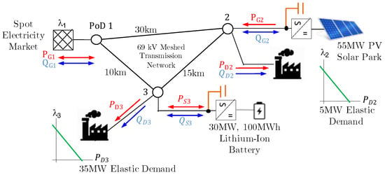
Figure 5.
Test system: EC with two industries, with PV and BESS assets connected to a CDS.
Both industries adopted a private agreement to constitute an EC with its own CDS, installing a 55 MW photovoltaic (PV) park, connected at node 2, and a 100 MWh/30 MW lithium-ion battery energy storage system (BESS), connected at node 3. The C-rate of the battery is 0.3. Notice that the 5 MW industry has enough space to install a 55 MW PV park, and the 35 MW industry has a space that is reduced enough to install a 30 MW/100 MWh BESS. By constituting an EC through a CDS, the cooperation between both industries is clearly stated.
We assume installation costs as follows: 1400 $/kWp for the PV plant, 200 $/kW for the BESS converter, and 400 $/kWh for the batteries. The installation cost of the closed distribution system (SCADA/EMS and transmission infrastructure) is set at $10 million. The total investment to constitute the CDS with distributed generation and storage assets is $133 million.
The set of spot prices is fixed as = [104.3 95.7 95.7 95.3 94.1 94.7 100.0 119.6 131.9 132.4 127.4 118.0 122.1 121.7 116.2 113.3 110.1 124.5 133.4 135.3 136.0 135.8 131.5 114.9] in $/MWh, as shown in Figure 6. The daily average forecasted (from 0:00 to 23:00) PV production in MW is = [0 0 0 0 0 0 8.11 18.23 28.84 38.04 44.80 50.43 52.54 48.48 45.88 38.09 28.73 18.29 7.68 0 0 0 0 0] MW. We consider the reactive capability of PV generators with a power factor ranging from 0.5 to 1 (leading and lagging). The lithium-ion battery at node 3 has a capacity of = 100 MWh. Inverter capacity is = 30 MW. The battery’s equivalent hours are 3.33 h. The depth of discharge parameters and are fixed at 20% and 100% in order to cover battery cooling consumption and reserves. We consider that the BESS inverter/rectifier equipment has reactive capabilities, with a power factor ranging from 0.5 to 1 (lagging and leading). For the sake of simplicity, we assume that the BESS efficiencies are equal to 1.
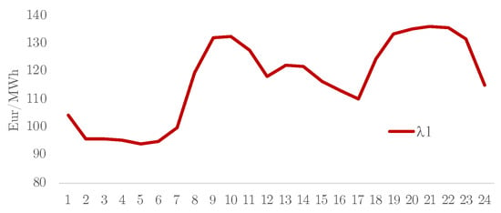
Figure 6.
Daily spot prices at frontier (PoD 1).
The CDS comprises a three-line 69 kV transmission system that interconnects all entities with node 1 (PoD): single-pole 69 kV with phase conductor ACSR 266.8 MCM 26/7, neutral/shield wire conductor 3/8″ copperweld. CDS line capacity limits , , and are set as 30 MW. The positive sequence impedance of the line is 0.2403 + j0.4815 ohm/km. The corresponding CDS admittance matrix (pu) is given by Equation (25):
Both industries can adjust their consumption patterns according to locational prices (CDS-LMP) as follows. The first industrial demand at node 2 is specified as = 5 MW, = 5.5 MW. CDS-LMP prices with = 100 $/MWh and = 1000 $/MWh are considered. The corresponding elasticity value at hour 7 is = 0.1111 1 (inelastic), and the slope is 100/5.55 = 18.1 $/MW2·h. The load power factor is 0.8 (lagging). The second industrial demand at node 3 is specified as = 35 MW, = 38.88 MW. Prices consider = 100 $/MWh and = 1000 $/MWh. The elasticity of load 2 at hour 7 is also = 0.1111 1 (inelastic), and the slope is 100/35.88 = 2.53 $/MW2·h. The load power factor is 0.8 (lagging). The base load curve is shown in Figure 7.
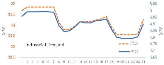
Figure 7.
Base load curve of industries connected at nodes 2 and 3.
Other predefined parameters are reference voltage at PoD is set as 1.0 pu. Capacity limits are established as active power at PoD = 60 MW, minimum voltage = 0.9 pu, and maximum voltage = 1.1 pu. The system’s bases are 10 MVA (power), 10 MWh (energy), and 69 kV (voltage).
As a reference or base scenario for comparison purposes, it is important to refer to the fact that energy purchased at the spot market by both industries is 941.8 MWh/day ($109,830 per day) when no EC is constituted.
5. Results
The optimization model stated in Section 3, Equations (1)–(21), has been applied to the case study described in Section 4, and the results are compared with the optimal active power dispatch proposed by [25] for closed distribution systems. The details of this model are included in Appendix A.
The nature of the problem is nonlinear, and all variables are continuous. The optimization model has been coded in Python 3.9.18 and solved using the Ipopt/Pyomo 6.6.1 environment (https://pypi.org/project/ipopt/, accessed on 1 November 2023) on a 2.6 GHz Apple MacBook Pro i7 with 16 GB of RAM. The resulting CPU time was 30 s. The interested reader can replicate the results and obtain the code at https://github.com/pmdeoliveiradejesus/DSOIEC (accessed on 18 September 2024).
5.1. The CDS/EC Optimal Dispatch Results
The resulting locational marginal prices CDS-LMPs ( and ) at nodes 2 and 3 are displayed in Figure 8a. These LMPs are similar to the spot prices at node PoD (Figure 6). The internal market price obtained with the reference method [25] is shown in Figure 8b. These internal prices coincide with the spot prices at node PoD (Figure 6). The LMPs are slightly higher than and since they incorporate the effect of active power losses. As indicated above, reference method [25] does not include a CDS detailed model.

Figure 8.
Proposed CDS−LMPs ( and ) and internal market price [25].
Figure 9a shows the resulting dispatch for active powers using the proposed methodology: the BESS facility ( and ), the load demands ( and ), the PV plant (), and the power exchanged at the PoD (). Figure 9b shows the resulting dispatch with the reference method [25].
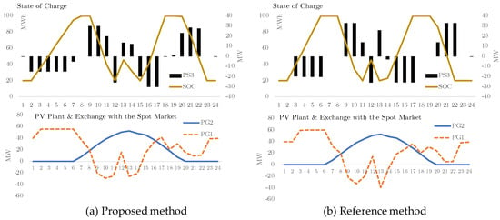
Figure 9.
Resulting active power dispatch for the proposed method and the reference method [25].
Notice that both results shown in Figure 9a,b are different but with a similar pattern. Both SoC curves are compatible with an arbitrage model. In Figure 9a,b, the BESS connected at bus 3 is charging () at low LMP prices (see Figure 8a) and internal market prices (see Figure 8b), respectively. On the other hand, the BESS is discharging () at high prices. In both cases, the BESS is purchasing energy at night and morning hours (0 to 7 h) and selling energy at noon (9–13 h) and afternoon hours (19–22 h). The BESS discharge stops at hours 13 and 15 due to the lower limit capacity constraint (20 MWh).
In general, as shown in Figure 9a,b, there was no curtailment at the PV generator in both cases. In this example, as expected, BESS and PV generation are unable to cover load demand at night. As a result, the EC should purchase energy () from the external grid at the PoD spot prices at hours with null or low solar irradiance. In hours with high solar irradiance, the EC diverts excess energy to the PoD due to the contribution of the photovoltaic plant and BESS. The main difference between Figure 9a,b with respect to the exchange with spot market in the reference model is that ref. [25] exchanges more energy with the spot market because this scheme has two frontiers. Under the proposed method, the EC is more resilient, with less need to buy and sell energy in the spot market.
For the proposed method, resulting responsive loads at nodes 2 and 3 ( and ) are near 5 and 35 MW, with small changes with respect to the base load curve shown in Figure 7 (strong inelastic behavior). In the case of the reference method [25], load demands are insensitive to price changes.
One key advantage of this proposal with respect to the reference method [25] is that it provides useful technical grid information that is required to facilitate exchange between producers and consumers. As indicated above, ref. [25] does not include the exact model of the CDS, disregarding the effects of reactive power dispatches. Thus, it is not possible to provide specific information about losses, voltage patterns, and reactive powers.
Figure 10 depicts some technical parameters of the CDS: overall network power losses, system voltages ( and ), and the reactive power dispatch ( and ). The energy losses are 19.0 MWh per day (the area below the power loss curve depicted above). Figure 10 also shows that the voltage magnitude at nodes 2 and 3 is stable around 1 pu due to adequate reactive power provision at nodes 2 and 3. System losses were considerably reduced when reactive power capability was enabled.
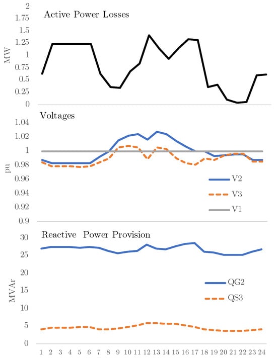
Figure 10.
Technical parameters of the CDS obtained with the proposed method.
The consolidated energy balance and economic results for the proposed and the reference method [25] are presented in Table 2 and Table 3, respectively.

Table 2.
Energy balance results.

Table 3.
Power dispatch economic results.
Notice that, under the proposed approach, the energy balance of the EC is slightly lower (1263.8 MWh/day) than the reference method (1282.7 MWh/day) [25]. This result is meaningful in consideration that the reference method does not include the impact of active power losses of the CDS. In other words, with this proposal, less exchange of energy with the spot market is required.
In the proposed method, the EC demand is 939.0 MWh per day. However, the total energy produced or consumed by the EC is 1263.8 MWh per day. The difference (185.7 and 120.1 MWh per day consumed by the BESS and the spot market, respectively) is required to be exchanged at different hours in order to maximize the overall EC surpluses. The CDS energy losses correspond to 1.5% of the total energy produced. If reactive powers are not included in the optimal dispatch by a constraint, such as = = 0, the resulting CDS energy losses would be higher (2.2%).
The proposed method yields a positive community welfare value of $470,685 per day, as all EC members have surplus positive values. As the reference method [25] loads do not change their consumption pattern when internal prices change over time, the resulting demand utility is zero and the community welfare is negative (−52,773 $/day), reflecting only the economic interchange with the spot market. In this case, the energy purchased is higher than the energy bought from the market.
A positive surplus for the CDS when LMPs are applied (3143 $/day) constitutes a key incentive to procure low power losses by means of an adequate reactive power provision.
If reactive powers are not included in the optimal dispatch by a constraint, such as = = 0, the resulting CDS surplus would be only $1347 per day with a smaller community welfare value of $468,842 per day with respect to the community welfare obtained with reactive power provision ($470,685 per day) shown in the first row of Table 3. In the case of reference method [25], the CDS-O surplus is higher ($44,052 per day) since the applied CDS tariffs = 0.0025 $/kWh and = 0.0075 $/kWh lead to a higher remuneration.
5.2. Economic Analysis: Is It Worth It for an EC to Invest in CDS, PV, and BESS?
In the results of the case study discussed in Section 5.1, the capital expenditure (CAPEX) requirement for a scenario of an industrial energy community with CDS, PV, and BESS assets is around $133 million. Therefore, based on the resulting economic flows, it is worth asking the question of whether it is attractive or not for ECs to invest in CDS, PV, and BESS.
Considering a base scenario with no EC, no BESS, and no CDS, both industries connected at buses 2 and 3 have to pay = $109,830 per day to cover their energy demand (941.8 MWh per day). These figures are important to determine whether the resulting new OPEX with CDS, storage, and renewable generation is lower than the OPEX of the base case without no EC. The resulting savings can be used to finance the project. In this case, by applying Equation (22), we find that operational savings are $109,830 − $54,924 = $54,906 per day = $20.0 million per year, almost a 50% reduction in operational expenses with respect to the base scenario.
Table 4 displays the financial indicators obtained for the savings achieved in the case study for annualized power dispatches and economic flows of the proposed method. Results are compared with the ones obtained with the reference method [25].

Table 4.
Financial indicators.
Considering annual figures, the 20-year net present value of the proposed method is $116.8 million, with a savings of $20 million per year. The benefit/cost ratio of the EC investment in CDS/PV/BESS is 1.88, with a payback time of 5.9 years (with a discount rate of 5%) and an internal rate of return of 14%.
On the other hand, the reference method [25] produces better and more optimistic results regarding the internal rate of return, payback, and benefit/cost ratio results. Considering annual figures, the 20-year net present value of the proposed method is slightly higher at $126.5 million, with a savings of $20.8 million per year. The benefit/cost ratio of the EC investment in CDS/PV/BESS is 1.95, with a lower payback time of 5.7 years and a higher internal rate of return of 14.6%. These results should be taken with caution since the reference model [25] does not incorporate the effect of energy losses on the CDS.
Finally, in order to consider a broader number of scenarios, a sensitivity analysis was carried out to assess financial results when varying some parameters, such as the price elasticity of demand and the average spot prices. Figure 11 shows how the internal rate of return and the payback time of the project are improved when loads become more elastic. Figure 12 shows how the internal rate of return and the payback time deteriorate when the project is exposed to higher spot prices.
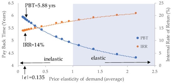
Figure 11.
Sensitivity analysis varying the elasticity of demand from 0.1 to 2.2.

Figure 12.
Sensitivity analysis varying the average spot price () between 50% and 150%.
5.3. Limitations of the Work
The proposed optimal power dispatch model assumes that CDS, PV, and BESS assets were previously sized by an energy planner. The sizing problem for an EC with CDS, as proposed by [25], is outside the scope of this paper and a matter for further research efforts.
6. Conclusions
This paper proposes an innovative optimal active and reactive power dispatch model for maximum energy community (EC) welfare conditions with storage and distributed generation facilities connected to closed distribution systems (CDSs).
There is no precedent for active and reactive power dispatch models for CDSs owned by ECs. Previous contributions in the literature do not consider the exact mathematical representation of active and reactive power flows in the CDS. As a key contribution, the optimal dispatch is obtained for the maximum social welfare of EC members, including the surplus of an internal CDS operator. In this model, the surplus of the external spot market is not included.
The proposed model has been applied to an illustrative case study, and the results show the importance of managing active and reactive energy from storage and renewable generation facilities in CDSs owned by energy communities. A reduction of 50% in operational expenditures in the energy community is observed, with a payback time of 5.9 years for investments in CDSs, renewable sources, and storage.
Author Contributions
Conceptualization, P.M.D.O.-D.J.; Investigation, P.M.D.O.-D.J.; Methodology, P.M.D.O.-D.J. and J.M.Y.; Validation, J.M.Y.; Writing—original draft, P.M.D.O.-D.J. and J.M.Y.; Writing—review and editing, P.M.D.O.-D.J. and J.M.Y. All authors have read and agreed to the published version of the manuscript.
Funding
This research received no external funding.
Data Availability Statement
The original contributions presented in the study are included in the article, further inquiries can be directed to the corresponding author.
Conflicts of Interest
The authors declare no conflicts of interest.
Nomenclature
| Acronyms | |
| AC | Alternating current |
| AMI | Advanced metering infrastructure |
| B/C | Benefit cost ratio |
| BESS | Battery energy storage system |
| CAPEX | Capital expenditure |
| CDS | Closed distribution system |
| CDS-O | Closed distribution system operator |
| CW | Community welfare |
| DoD | Depth of discharge |
| EC | Energy community |
| EMS | Energy management system |
| IRR | Internal rate of return |
| LMP | Locational marginal prices |
| NPV | Net present value |
| OPEX | Operational expenditures |
| PBT | Payback time |
| PoD | Point of delivery |
| PV | Photovoltaic system |
| SCADA | Supervisory control and data acquisition |
| SGC | Smart grid conceptual |
| SM | Smart meters |
| SO | System operator |
| Subscripts | |
| n | Number of nodes of the CDS |
| k | CDS node number |
| Superscripts | |
| t | Hour |
| Greek letters | |
| Linear marginal coefficient | |
| Quadratic marginal coefficient | |
| Discharging efficiency | |
| Charging efficiency | |
| Set of spot prices | |
| Spot price at frontier node 1 | |
| CDS-LMP at node k | |
| Price that the demand is willing to pay at node k | |
| Producer economic surplus | |
| Demand economic surplus | |
| Storage economic surplus | |
| CDS economic surplus | |
| Use of the network tariff (reference method) | |
| Upper BESS capacity limit | |
| Lower BESS capacity limit | |
| Angle at node k | |
| Internal market price (reference method) | |
| CDS-O energy selling price (reference method) | |
| CDS-O energy purchasing price (reference method) | |
| Latin letters | |
| Profit of industries connected at node k (reference method) | |
| Profit of the CDS operator (reference method) | |
| B | Susceptance matrix |
| Element of B | |
| Capacity of the BESS at node k | |
| C-Rate of the BESS at node k | |
| Energy bought by demands | |
| Energy bought by the spot market | |
| Energy sold by the generators | |
| Energy sold by the spot market | |
| Energy purchased by the BESS | |
| Energy sold by the BESS | |
| G | Conductance matrix |
| Element of G | |
| Slope of the demand curve at node k | |
| Energy payments without EC | |
| Energy payments with EC | |
| Average power produced at node k hour t | |
| Power consumed at node k at equilibrium | |
| Power consumed at node k | |
| Power injection of the BESS system at node k | |
| Maximum power consumption at node k | |
| Maximum operational power generation at node k | |
| Active power flow between nodes i and j (reference method) | |
| Active power discharged at BESS at node k (reference method) | |
| Active power discharged at BESS at node k (reference method) | |
| Active power bought from the market at node k (reference method) | |
| Active power sold to the market at node k (reference method) | |
| Reactive power generated at node k | |
| Reactive power consumed at node k | |
| Reactive power injected by BESS at node k | |
| Minimum reactive power flow operational level | |
| Maximum reactive power flow operational level | |
| Minimum BESS reactive power flow operational level | |
| Maximum BESS reactive power flow operational level | |
| State of the charge of the BESS at node k | |
| Apparent power flow between nodes i and j | |
| Maximum apparent power flow operational level | |
| T | Time span |
| u | Binary decision variable |
| Utility of demand at node k | |
| Utility of demand | |
| Y | Admittance matrix |
| v | Binary decision variable |
| Voltage magnitude at node k | |
| Minimum operational voltage level at node k | |
| Maximum operational voltage level at node k | |
| w | Binary decision variable |
| z | Binary decision variable |
Appendix A. Reference Method [25]
In this paper, for comparison purposes, we apply, to the case study discussed in Section 4, the power dispatch model for a closed distribution system (CDS) proposed by [25]. The original optimization model states two objective functions to be maximized under a bi-level approach: one for the CDS operator profit and the other for the sum of all electricity profits of industries gathered in an energy community.
We assume that, as in our proposal discussed in Section 3, the profit of the CDS operator (CDS-O) is a part of the profit of the energy community; therefore, the objectives must be maximized together. Under this approach, two frontiers are considered. This means that each industry has its own point of delivery (PoD) with the public service network, as seen in Figure A1. Notice that the CDS corresponds to a simple link between industry 1 and industry 2, disregarding the effect of resistances and reactances. Only active power is considered.
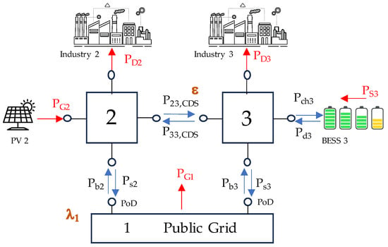
Figure A1.
EC scheme with two points of delivery and a CDS [25].
The optimization problem is stated using the nomenclature of this paper as follows:
subject to
This optimization model is a Mixed-Integer Problem (MIP), which can be suitably solved with standard tools such as GAMS or Gurobi. We include a script in GAMS Studio version 47 to solve this problem in https://github.com/pmdeoliveiradejesus/DSOIEC (accessed on 18 September 2024).
References
- Rodrigues, S.D.; Garcia, V.J. Transactive energy in microgrid communities: A systematic review. Renew. Sustain. Energy Rev. 2023, 171, 112999. [Google Scholar] [CrossRef]
- Comisión Regulación Energía y Gas. CREG 701-051-2024: Directive by Which the Regulation for the Integration of Energy Communities into the National Energy System Is Harmonized and Other Provisions are Dictated. Available online: https://gestornormativo.creg.gov.co/gestor/entorno/docs/originales/Proyecto_Resoluci%C3%B3n_CREG_701_051_2024/ (accessed on 15 August 2024).
- Council of European Energy Regulators. Status Review on the Transposition of Unbundling Requirements for DSOs and Closed Distribution System Operators; Report C12-UR-47-03; Council of European Energy Regulators: Brussels, Belgium, 2013. [Google Scholar]
- European Union. Directive 2019/944/CE on the Internal Market for Electricity. Available online: https://eur-lex.europa.eu/legal-content/EN/TXT/?uri=celex%3A32019L0944 (accessed on 15 August 2024).
- Caramizaru, A.; Uihlein, A. Energy Communities: An Overview of Energy and Social Innovation; Publications Office of the European Union: Luxembourg, 2020. [Google Scholar]
- Bundesnetzagentur. Section 210, German Energy Industry Act (Energiewirtschaftsgesetz (EnWG)); Bundesnetzagentur: Mainz am Rein, Germany, 2021. [Google Scholar]
- Official State Gazette of Spain. Royal Decree-Law (RDL) 314-2023, 25 April 2023. Available online: https://www.boe.es/eli/es/rd/2023/04/25/314 (accessed on 15 August 2024).
- Conselho de Ministros de Portugal. Decreto-Lei no. 15/2022 de 14 de Janeiro 2022. Available online: https://diariodarepublica.pt/dr/en/detail/decree-law/15-2022-177634016 (accessed on 15 August 2024).
- Italian Energy Authority. Resto Integrato dei Sistemi di Distribuzione Chiusi, Resolution 539; Italian Energy Authority: Milan, Italy, 2015. [Google Scholar]
- Carlini, C.; Moneta, D.; Angelucci, V. Energy Community: The Italian Scenario within the Pan-European Framework; CIRED: Paris, France, 2018. [Google Scholar]
- Agabus, H.; Korõtko, T.; Kull, K.; Rosin, A.; Palu, I. Potential Assessment of Closed Distribution System Uptake in Estonia. In Proceedings of the 2023 IEEE 17th International Conference on Compatibility, Power Electronics and Power Engineering (CPE-POWERENG), Tallinn, Estonia, 14–16 June 2023; pp. 1–5. [Google Scholar]
- Ruester, S.; Schwenen, S.; Batlle, C.; Pérez-Arriaga, I. From distribution networks to smart distribution systems: Rethinking the regulation of European electricity DSOs. Util. Policy 2014, 31, 229–237. [Google Scholar] [CrossRef]
- Ghadi, M.J.; Ghavidel, S.; Rajabi, A.; Azizivahed, A.; Li, L.; Zhang, J. A review on economic and technical operation of active distribution systems. Renew. Sustain. Energy Rev. 2019, 104, 38–53. [Google Scholar] [CrossRef]
- Mallet, P.; Granstrom, P.O.; Hallberg, P.; Lorenz, G.; Mandatova, P. Power to the people!: European perspectives on the future of electric distribution. IEEE Power Energy Mag. 2014, 12, 51–64. [Google Scholar] [CrossRef]
- Duan, Y.; Zhao, Y.; Hu, J. An initialization-free distributed algorithm for dynamic economic dispatch problems in microgrid: Modeling, optimization and analysis. Sustain. Energy Grids Netw. 2023, 34, 101004. [Google Scholar] [CrossRef]
- Zhang, X.; Wang, Z.; Lu, Z. Multi-objective load dispatch for microgrid with electric vehicles using modified gravitational search and particle swarm optimization algorithm. Appl. Energy 2022, 306, 118018. [Google Scholar] [CrossRef]
- Ishraque, M.F.; Shezan, S.A.; Ali, M.; Rashid, M. Optimization of load dispatch strategies for an islanded microgrid connected with renewable energy sources. Appl. Energy 2021, 292, 116879. [Google Scholar] [CrossRef]
- Lu, X.; Liu, Z.; Ma, L.; Wang, L.; Zhou, K.; Feng, N. A robust optimization approach for optimal load dispatch of community energy hub. Appl. Energy 2020, 259, 114195. [Google Scholar] [CrossRef]
- Wen, L.; Zhou, K.; Yang, S.; Lu, X. Optimal load dispatch of community microgrid with deep learning based solar power and load forecasting. Energy 2019, 171, 1053–1065. [Google Scholar] [CrossRef]
- Shuai, H.; Fang, J.; Ai, X.; Tang, Y.; Wen, J.; He, H. Stochastic optimization of economic dispatch for microgrid based on approximate dynamic programming. IEEE Trans. Smart Grid 2018, 10, 2440–2452. [Google Scholar] [CrossRef]
- Nwulu, N.I.; Xia, X. Optimal dispatch for a microgrid incorporating renewables and demand response. Renew. Energy 2017, 101, 16–28. [Google Scholar] [CrossRef]
- Li, C.; De Bosio, F.; Chen, F.; Chaudhary, S.K.; Vasquez, J.C.; Guerrero, J.M. Economic dispatch for operating cost minimization under real-time pricing in droop-controlled DC microgrid. IEEE J. Emerg. Sel. Top. Power Electron. 2016, 5, 587–595. [Google Scholar] [CrossRef]
- Shamsi, P.; Xie, H.; Longe, A.; Joo, J.Y. Economic dispatch for an agent-based community microgrid. IEEE Trans. Smart Grid 2015, 7, 2317–2324. [Google Scholar] [CrossRef]
- Wu, H.; Liu, X.; Ding, M. Dynamic economic dispatch of a microgrid: Mathematical models and solution algorithm. Int. J. Electr. Power Energy Syst. 2014, 63, 336–346. [Google Scholar] [CrossRef]
- Fioriti, D.; Poli, D.; Frangioni, A. A bi-level formulation to help aggregators size Energy Communities: A proposal for virtual and physical Closed Distribution Systems. In Proceedings of the 2021 IEEE International Conference on Environment and Electrical Engineering and 2021 IEEE Industrial and Commercial Power Systems Europe (EEEIC/I&CPS Europe), Bari, Italy, 7–10 September 2021; pp. 1–6. [Google Scholar]
- Heydt, G.T. The next generation of power distribution systems. IEEE Trans. Smart Grid 2010, 1, 225–235. [Google Scholar] [CrossRef]
- Heydt, G. Pricing and Control in the Next Generation Power Distribution System. IEEE Trans. Smart Grid 2012, 3, 907–914. [Google Scholar] [CrossRef]
- De Oliveira-De Jesus, P.; Antunes, C.H. Economic valuation of smart grid investments on electricity markets. Sustain. Energy Grids Netw. 2018, 16, 70–90. [Google Scholar] [CrossRef]
- Schweppe, F.; Caramanis, M.; Tabors, R.; Bohn, R. Spot Pricing of Electricity; The Kluwer International Series; Springer Science & Business Media: Berlin/Heidelberg, Germany, 1988. [Google Scholar]
- Diaz-Caballero, O.; De Oliveira-De Jesus, P.M.; Yusta, J.M. Market equilibrium analysis considering electric vehicle aggregators and wind power producers without storage capabilities. In Proceedings of the 2020 IEEE 14th International Conference on Compatibility, Power Electronics and Power Engineering (CPE-POWERENG), Setubal, Portugal, 8–10 July 2020; Volume 1, pp. 382–387. [Google Scholar]
- Stoft, S. Power System Economics: Designing Markets for Electricity; John Wiley and Sons: New York, NY, USA, 2003. [Google Scholar]
Disclaimer/Publisher’s Note: The statements, opinions and data contained in all publications are solely those of the individual author(s) and contributor(s) and not of MDPI and/or the editor(s). MDPI and/or the editor(s) disclaim responsibility for any injury to people or property resulting from any ideas, methods, instructions or products referred to in the content. |
© 2024 by the authors. Licensee MDPI, Basel, Switzerland. This article is an open access article distributed under the terms and conditions of the Creative Commons Attribution (CC BY) license (https://creativecommons.org/licenses/by/4.0/).