Abstract
Diagnosing faults is crucial for ensuring the safety and reliability of medium-voltage direct current (MVDC) systems. In this study, we propose a bidirectional long short-term memory (Bi-LSTM)-based fault diagnosis scheme for the accurate classification of faults occurring in MVDC systems. First, to ensure stability in case a fault occurs, we modeled an MVDC system that included a resistor-based fault current limiter (R-FCL) and a direct current circuit breaker (DCCB). A discrete wavelet transform (DWT) extracted the transient voltages and currents measured using DC lines and AC grids in the frequency–time domain. Based on the digital signal normalized by the DWT, using the measurement data, the Bi-LSTM algorithm was used to classify and learn the types and locations of faults, such as DC line (PTP, P-PTG, and N-PTG) and internal inverter faults. The effectiveness of the proposed fault diagnosis scheme was validated through comparative analysis within the four-terminal MVDC system, demonstrating superior accuracy and a faster diagnosis time compared to those of the existing schemes that utilize other AI algorithms, such as the CNN and LSTM. According to the test results, the proposed fault diagnosis scheme detects MVDC faults and shows a high recognition accuracy of 97.7%. Additionally, when applying the Bi-LSTM-based fault diagnosis scheme, it was confirmed that not only the training diagnosis time (TraDT) but also the average diagnosis time (AvgDT) were 0.03 ms and 0.05 ms faster than LSTM and CNN, respectively. The results validate the superior fault clarification and fast diagnosis performance of the proposed scheme over those of the other methods.
1. Introduction
An MVDC system can supply power for shipping services, propulsion loads in shipboard electrical systems, onboard DC marine vessels, and remote area mining sites. This is attributed to several advantages, including reduced losses, lower complexity with fewer conversion stages, relaxed synchronization requirements, and the ease of integrating multiple energy storage systems [1,2,3]. However, when such multi-terminal MVDC systems experience a fault contingency, they are subjected to a rapid rise in current due to the discharge of the converter capacitor [4]. If a fault is not promptly isolated and cleared, it can potentially damage the power electronic devices within the voltage source converter (VSC) due to the substantial fault current. Moreover, a non-faulty line and a broader MVDC system may also suffer adverse effects. Therefore, faults and their locations in DC systems must be quickly and accurately determined to eliminate them [5,6].
Protecting DC grids is particularly challenging due to the typically high magnitude of the DC fault currents, which often peak within milliseconds of a fault’s onset [7]. Fault detection, diagnosis, and clarification are also challenging. When identifying a fault, the line on which it occurred can be isolated; this also ensures its rapid reintegration back into the DC system [8,9]. Thus, fault diagnosis within DC systems, including MVDC systems, is crucial for enhancing system safety and reliability, facilitating efficient operation. Fault diagnosis is a prominent area of research in DC systems, with numerous studies conducted to improve their effectiveness [10].
The traditional fault detection algorithm in DC systems, such as overcurrent, undervoltage, and rate-of-change among the current or voltage methods, are widely used [11,12,13,14]. However, these approaches often cannot detect faults with low or high resistance, and their selectivity can be problematic in meshed MVDC configurations. To achieve greater sensitivity and selectivity, some studies employed fault detection algorithms based on differential and directional currents, which rely on communication [15,16]. Despite the advantages of these schemes, they allow for fault detection, but do not enable the accurate classification of the fault type and location.
The studies on fault detection and diagnosis in HVDC systems are extensive [17,18,19]. One study [17] reviews the fault detection and location estimation techniques in multi-terminal HVDC systems, focusing particularly on protection strategies for systems utilizing voltage source converter (VSC) technology. However, this study only provides a comprehensive overview of the fault detection and location estimation techniques in multi-terminal HVDC systems. In a different study [18], a new method combining Bayesian-optimized long short-term memory (LSTM) networks with the discrete wavelet transform (DWT) is proposed to detect faults in modular multilevel converter (MMC)-based HVDC systems. Another study [19] proposes a novel protection scheme that combines the DWT with artificial neural networks (ANNs) for fault detection and classification in meshed multi-terminal HVDC grids. However, the approaches in these studies [18,19] are specifically focused on HVDC systems; their applicability to MVDC systems is yet to be explored.
Several other studies proposed fault detection and classification methods specifically for MVDC systems. For example, in [20], an active impedance estimation (AIE) technique was proposed for fault classification and localization. However, obtaining an accurate estimation within a short timeframe remains a significant challenge. Another study [21] proposed a method combining the wavelet transform (WT) and the self-organized adaptive resonance theory (ART) neural network to utilize both low- and high-frequency fault signals for advanced line diagnosis. However, selecting the appropriate wavelet function and decomposition level is crucial to balance accurate fault detection and computational efficiency. In ref. [22], a self-healing procedure was proposed, which considers communication delays and measurement unit failures to identify unusual data behavior, whether caused internally or externally, to prevent incorrect computations. However, the method applied in [22] does not determine the fault’s location and type.
Recently, AI-based algorithms were explored for fault diagnosis in DC systems [23,24,25,26,27,28,29]. In ref. [23], an artificial neural network (ANN)-based method for fault detection in VSC-HVDC which involved using only the measured voltage waveforms at the rectifier substation was presented. Another paper [24] proposed a diagnosis scheme based on an ANN and high-frequency components to detect DC fault currents. In ref. [25], a method combining WT multi-resolution analysis (MRA) with ANNs was proposed for fault detection and classification in MVDC systems. In ref. [26], discrete wavelet analysis and a fuzzy neural pattern recognition approach were employed to detect the fault lines and locations by considering the interactions of short-circuit-induced traveling waves among the lines within the same loop. A different paper [27] proposed a transient signal identification method based on wavelet entropy and a support vector machine (SVM) using the high-frequency signals generated by fault transients in HVDC. In ref. [28], a novel fault diagnosis method based on short-time wavelet entropy was proposed, integrating the long short-term memory (LSTM) algorithm with an SVM. In ref. [29], a DC line fault diagnosis method based on LSTM was proposed to improve the response and accuracy of the transient-based methods. However, the proposed diagnosis method in [23,24,25,26,27,28,29] was applied only to DC fault classification, excluding the inverter faults in DC systems.
Further studies on AI-based fault diagnosis for multi-terminal DC systems were conducted [30,31,32]. One paper [30] proposed a Bi-GRU-based end-to-end fault diagnosis method that eliminated the need for manual feature extraction and classifier selection while offering a strong feature extraction capability without complex data preprocessing. Another paper [31] presented a data-driven protection framework designed to improve the fault detection accuracy and reliability in multi-terminal DC networks, while ensuring strong interpretability by clearly presenting the extracted features and the softmax regression classifier mathematics. In ref. [32], a novel and straightforward fault detection algorithm was presented, combining the ANN and discrete wavelet transform (DWT) methods. However, the proposed diagnosis method in [30,31,32] was unable to detect faults across all the regions of the DC system.
An AI-based fault diagnosis scheme is proposed in this paper to enhance the accuracy of fault diagnosis in MVDC systems. The proposed scheme analyzes data on both the DC line and internal inverter faults, with digital signal processing performed using the discrete wavelet transform (DWT) algorithm. The processed data are then used to develop a classification model of fault location and type using a bidirectional long short-term memory (Bi-LSTM) network, targeting both the DC line and internal inverter faults. Additionally, a resistor-based fault current limiter (R-FCL) and a direct current circuit breaker (DCCB) are modeled and applied to the system to suppress the fault current peak value. A case study is simulated to verify the ability of the proposed diagnosis scheme to accurately diagnose faults in MVDC systems.
The main contributions of this paper are summarized as follows:
- To the best of our knowledge, this study is the first to develop a fault diagnosis scheme using the Bi-LSTM algorithm in an MVDC system. The Bi-LSTM is used to develop a highly accurate classification model for the location and type of faults, including both DC line and internal inverter faults.
- To quickly alleviate faults in the MVDC system, an R-FCL and a DCCB are implemented at both the ends of each DC line, and the two devices are appropriately combined to ensure system stability in the event of a fault.
- The proposed fault diagnosis method is verified for reliability and accuracy by comparison with the existing methods, such as the CNN and LSTM in a four-terminal MVDC system.
2. System Configuration
Figure 1 presents a schematic diagram of an ±35 kV MVDC system comprising four VSCs and associated grids. Each VSC is connected to the PCC of its respective grid via a high-voltage feeder. The VSCs are modeled using a two-level switching approach. The local controller of VSC1 is responsible for DC voltage regulation (V1ref), while the local controllers of the VSC2–4 manage active power control (P2–4ref). Additionally, all the DC links are bipolar configurations to reflect the practical considerations [33]. Each DC line is represented by a PI model, with R-FCLs and DCCBs installed at both ends of the line to mitigate peak fault currents and isolate faults, respectively. In the PI model, ‘n’ represents the distance from the DC terminal to the fault location, with the entire DC line distance normalized to 1. In this paper, if the DC line is 50 km long and a fault occurs at the 20 km point, ‘n’ is 0.4. The input data for the proposed fault diagnosis scheme include the current (Idc1–4_p,n) and voltage (Vdc1–4_p,n) in each DC line, as well as the current (iac1–4) and voltage (vac1–4, vpcc1–4) in the AC grids [34].
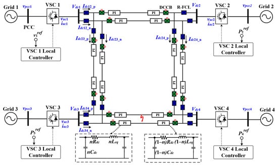
Figure 1.
Schematic diagram of the MVDC system to verify the effectiveness of the proposed diagnosis scheme.
3. Structure of the R-FCL and DCCB
In this paper, R-FCLs and DCCBs are implemented at both ends of each DC line to swiftly mitigate faults in the MVDC system. The R-FCL is a protection system comprising resistors and switches arranged in parallel to mitigate the fault currents. The R-FCL can promptly adjust the current limiter impedance without the need for additional fault detection and control systems, thus serving as an effective technical solution to address short-circuit current issues in MVDC systems [35,36]. Properly setting the resistance value (Rf) in the R-FCL is crucial for reducing the peak fault values. Figure 2 illustrates the structure of the R-FCL and provides a comparison of the Idc1_peak values corresponding to various Rf values to determine the optimal Rf value. In the R-FCL system, the switch remains closed under normal conditions; however, in the event of a fault, the switch opens, and the fault current is influenced by Rf, thereby limiting the fault current. In the system depicted in Figure 1, when a PTP fault with a fault resistance of 1 Ω occurs at a distance of 25 km along the DC12 line, the Idc1_peak value is determined after applying Rf values ranging from 3 Ω to 30 Ω. These resultant values represent the outcomes when the R-FCL and the DCCB are jointly applied. Consequently, it is verified that the lowest Idc1_peak value of 0.95 kA is achieved when Rf is set to 13 Ω.
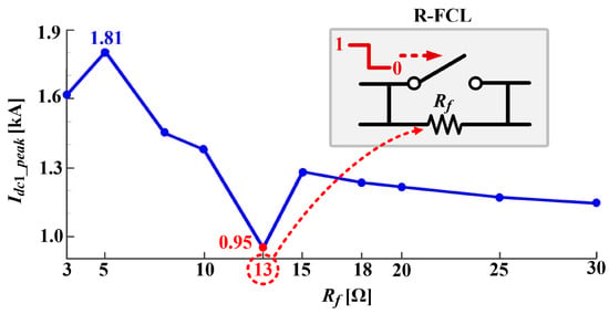
Figure 2.
Schematic diagram of the MVDC system to verify the effectiveness of the proposed diagnosis scheme. Comparison with Idc1_peak according to change in Rf.
Figure 3 illustrates the structure of the DCCB, as modeled in this paper. DCCBs are available in various structural configurations, including arc-based and bidirectional series Z-source circuit breakers (ACBs and ZCBs) utilizing Z-source inductors and thyristors and hybrid CBs [37,38]. In this paper, a simple power electronic circuit breaker (PECB) employing two MOSFETs connected in series are employed to ensure rapid operation and fault current limitation. Note that the main purpose of this study is not to design an efficient and fast DCCB, but to develop a fault diagnosis scheme with a high accuracy. In Figure 3, each MOSFET’s drain is connected to a DC line, and the sources of the two MOSFETs are interconnected. In the event of a fault, an operation signal is transmitted from ‘1’ to ‘0’ to the gate of each MOSFET, causing both the MOSFETs to open and mitigate the fault.

Figure 3.
Structure of DCCB.
4. Proposed Bi-LSTM Based on a Fault Diagnosis Scheme
In this section, we present the proposed fault diagnosis scheme designed to enhance the reliability of MVDC systems in the event of a fault. Accuracy and the diagnosis time are critical factors in evaluating the effectiveness of a fault diagnosis scheme. Insufficient accuracy may result in incorrect system responses during a fault event. Additionally, in MVDC systems, particularly in the case of DC line faults, such as pole-to-pole (PTP) and pole-to-ground (PTG) faults, slow diagnosis can have severe consequences because the absence of a zero-crossing point complicates fault clearance.
As illustrated in Figure 4, the proposed fault diagnosis scheme, developed to improve both accuracy and diagnosis, consists of the following two steps:
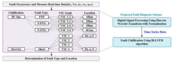
Figure 4.
Flowchart of proposed fault diagnosis scheme.
- Data signal processing transforms the fault data (Idc, Vdc, iac, vac, and vpcc) measured during MVDC system faults, which are modeled in MATLAB/Simulink R2024a, using the discrete wavelet transform (DWT).
- Fault classification involves utilizing the Bi-LSTM network to classify the location and type of faults, including DC line (PTP, P-PTG, and N-PTG) and internal inverter faults (inverter short-circuit), based on the processed digital data.
Finally, based on the fault diagnosis results predicted in steps 1 and 2, the faults in the MVDC system are detected and classified.
4.1. Digital Signal Processing Based on the DWT with Normalization
The DWT is widely utilized in wavelet analysis due to its advantageous characteristics, including its enhanced speed and accuracy, efficient selectivity, and higher resolution for transient signals. The DWT enables a comprehensive analysis of transient signals, thereby facilitating precise fault detection in MVDC systems.
In the DWT, the parameters ‘n’ and ‘m’ are integers that control the translation and dilation of the mother wavelet, respectively, corresponding to the sampling number and the decomposition level. In addition, ‘Ψ’ means the mother wavelet. WT analysis encompasses various families of wavelets, such as the Daubechies (dbN), Symlets (symN), and Coiflets families (coifN), among others, which can be employed as the mother wavelet. In this context, ‘N’ denotes the order of the wavelet function. dbN wavelets are often preferred over the other wavelet families due to their superior capabilities in signal recognition and noise removal [39]. Accordingly, dbN wavelets are considered as particularly suitable for use as the mother wavelet in this study. Within the framework of the DWT, decomposing a fault signal allows for the detailed evaluation of the fault conditions. The approximation (A) and detail coefficients (d) in the DWT are typically expressed as in Equations (2)–(4).
Here, CN−1−k represents the scaling coefficient, N is the total number of scaling coefficients, and bk is the reconfigured coefficient. For feature extraction, multi-resolution signal decomposition is utilized to decompose the fault signal into both approximate and detailed components. Figure 5 presents the Idc results, converted from real data under normal and fault conditions using the DWT with a db3 mother wavelet. The fault type is PTP, which was initiated at 1.0 s at 25 km along DC line 12 and lasting for 0.1 s. As shown in Figure 5b, the wavelet-filtered signal (WFS) under fault conditions is observed to increase up to 10.0 and increase 10 times compared to that under normal conditions. This confirms that the DWT effectively processes abnormally fluctuating fault data in time series analysis.
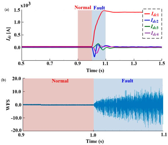
Figure 5.
DWT data in MVDC system: (a) Idc data, (b) DWT data in normal and fault condition.
4.2. Fault Clarification Based on the Bi-LSTM Algorithm
Figure 6 illustrates the cell structure of Bi-LSTM. Bi-LSTM enhances standard LSTM by processing the input data bidirectionally, incorporating both the forward and backward directions. It comprises forward LSTM that processes the input sequence from start to finish and backward LSTM that processes the sequence in reverse [40]. The hidden states from both directions are typically concatenated or combined at each time step to yield a comprehensive representation of the input. The primary advantage of employing Bi-LSTM lies in its ability to capture the context and long-term dependencies in both the directions, thereby facilitating a deeper understanding of the input sequence. This algorithm is particularly well suited for accurate fault classification using the extensive and long-term processed data generated in the earlier stage. In Figure 6, Bi-LSTM consists of multiple LSTMs, which is composed of three key gate structures: the forget, input, and output gates. The first gate, known as the forget gate (ft), is responsible for discarding irrelevant information. The second gate, referred to as the input gate (it), extracts relevant information from the preprocessed data and stores it in the cell state. The third gate, the output gate (ot), classifies the information, specifically the fault types in the context of the proposed study. The function for each gate, including the update (ct) and new cells (ct*), is as follows:

Figure 6.
Structure of Bi-LSTM.
In the LSTM architecture, four internal layers effectively propagate information, in addition to the three gates that regulate ct information. In the first layer, ft selects the previous cell state (ct−1) and determines the amount of information from ct−1 to retain in ct. ft reads the previous block’s output (ht−1) and the feature vector input at time instance t (xt), yielding a value between 0 and 1 for each element in the previous cell state. A value of 0 indicates firm discarding, while a value of 1 signifies firm reservation. In the second layer, the input gate (it) determines how much information from xt is stored in the cell state. Concurrently, tanh generates a new candidate vector (ct*), incorporating all the potential values to be added to the cell state. Subsequently, it and ct* are multiplied and added to the current state through an addition operation, progressing to the third layer. In the third layer, the cell state is updated to integrate new information and discard the previous state. Finally, the output layer selects the pertinent information and presents it as the output result. This layer employs a Sigmoid function for output selection. Subsequently, the cell state is processed through the tanh function and multiplied by ot. In this scenario, the variable ot transforms ct into the vector ht, which exposes the cell-state memory to the remainder of the network. At each time step of the sequence data, Wf, Wi, Wc, and Wo represent the learnable weights, while bf, bi, bc, and bo denote the biases, respectively.
5. Case Study
5.1. Test Conditions
The proposed fault diagnosis scheme described in Section 4 is validated through simulations conducted using MATLAB/Simulink R2024a. Table 1 presents the MVDC system parameters employed for fault training and testing, with the fault resistance set to 1 Ω. As seen in Table 2, the training and testing datasets consist of 31,348 and 12,908 samples, respectively, so they are significantly larger than those used in the other studies [41,42]. As illustrated in Figure 7, to enhance practical implementation, the training and testing processes are carried out by subdividing the fault locations and types. In Figure 7, the fault data used in the fault diagnosis method are primarily categorized into DC line (PTP, P-PTG, and N-PTG) and inverter short-circuit faults. For the DC line faults, the training dataset comprises data recorded when the faults occurred at 10, 20, and 40 km along the DC line. Subsequently, tests are performed on the faults occurring at 30 km along the DC line to assess the scheme’s accuracy and diagnosis time. For the inverter short-circuit faults, the training dataset includes the data from the A and B phases short-circuited to the P and N phases, while the test dataset comprises the data from the C phase short-circuited to the P and N phases. In all the cases, the current and voltage (Idc and Vdc) flowing through the DC line, those (iac and vac) measured at the AC terminal (the inverter input terminal), and the voltage (vpcc) measured at the PCC are used. Based on the data transformed from measured signals into DWTs, the effectiveness of the proposed fault diagnosis scheme is validated by comparing its accuracy and diagnosis time against those of the conventional fault diagnosis schemes, including LSTM and the CNN.

Table 1.
MVDC Parameters for Training and Testing.

Table 2.
Number of Samples for Training and Testing.
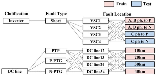
Figure 7.
MVDC fault scenario considering fault type and location.
5.2. Verification of the Effectiveness of Proposed Fault Diagnosis Scheme in a Four-Terminal MVDC System
In this section, the proposed fault diagnosis scheme utilizing BI-LSTM is verified to have higher accuracy in fault learning and classification and a faster diagnosis time compared to those of the existing AI algorithms, such as LSTM and the CNN. Figure 8 illustrates the accuracy and average diagnosis time per sample (avgDT) for the various fault diagnosis schemes, further demonstrating the effectiveness of the proposed scheme. In particular, Figure 8a shows that the proposed scheme achieves a final accuracy of 97.7%, representing an improvement of between 0.9% and 0.5% compared to the accuracy of LSTM and the CNN. In Figure 8b, the avgDT for the proposed fault diagnosis scheme is 3.21 ms, which is 0.03 ms and 0.05 ms faster than those of LSTM and the CNN, respectively. This result confirms that the proposed fault diagnosis scheme maintains high accuracy within the allowable diagnosis time range of 10 ms [43]. Table 3 and Figure 9 present the TraDT and the TesDT of the proposed fault diagnosis scheme and the existing diagnosis scheme. The TraDT and the TesDT stand for the training and test times per fault sample, respectively. In Table 3, the TesDT of the proposed scheme is the same as the existing scheme at 3.05 ms, but the TraDT is confirmed to be 0.09 ms and 0.18 ms faster than those of LSTM and the CNN. This result verifies the effect of not only high accuracy, but also fast diagnosis when the proposed scheme is applied. Figure 10 presents the confusion matrix of the proposed fault diagnosis scheme, including the processing data using the DWT. The confusion matrix compares the actual fault type (target class) with the model’s diagnostic results (output class). As can be seen in Figure 10, when the proposed fault diagnosis scheme is trained and tested, it shows higher accuracy in the inverter short-circuit, but lower accuracy in the PTP fault compared to those of the other faults. In particular, it is confirmed that the probability that the actual fault type and the diagnosis results are different is high at 22.2% in the case of the PTP 13 fault. The results in Table 4 show that the accuracy of the proposed method is 84.2% for the PTP fault, which has lower diagnostic accuracy than the other faults, and that the proposed method is 5.9% and 2.7% better than LSTM and the CNN, respectively. By applying the Bi-LSTM-based fault diagnosis scheme to the four-terminal MVDC system and analyzing the results, the accuracy and diagnosis time for each fault are improved compared to those of the conventional diagnosis schemes. Table 5 lists the training times of the AI-based fault diagnosis scheme, including the Bi-LSTM-based scheme. This indicates the durations in minutes (“m”) and seconds (“s”). The proposed scheme required the shortest training time, totaling 6 m 9 s, mainly due to its simplicity. In this study, the effectiveness of the proposed scheme on the accuracy and diagnosis time when the training system and the test system are different was not verified. We plan to verify the effect of the proposed fault diagnosis scheme in the future.

Figure 8.
Comparison of accuracy and diagnosis time in fault diagnosis schemes: (a) accuracy, (b) AvgDT.

Table 3.
Comparison of diagnostic time between the proposed method and other methods.
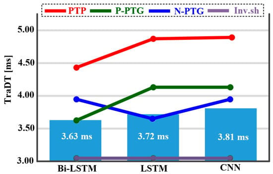
Figure 9.
Comparison of TraDT by each fault in fault diagnosis schemes.
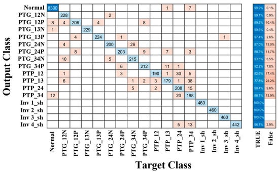
Figure 10.
Confusion matrix of proposed fault diagnosis scheme.

Table 4.
Comparison of accuracy between the proposed method and other methods according to fault types.

Table 5.
Training times required by the AI-based fault diagnosis scheme.
5.3. Verification of the Effectiveness of R-FCL and DCCB
Figure 11 presents the resulting waveform of Idc1 when the R-FCL and the DCCB are individually incorporated into the MVDC test system. A PTP fault transpired on the DC12 line at a distance of 25 km with a resistance of 1 Ω. The fault onset occurred at 0.5 s, lasting for 0.1 s. In Figure 11, the ‘blue’ and ‘green’ lines depict the resulting waveforms of Idc1 when only the R-FCL is applied and when neither the R-FCL nor the DCCB are employed, respectively. The utilization of the R-FCL alone results in an Idc1_peak value of 22.19 kA, marking a reduction of 19.84% compared to the Idc1_peak value when neither the R-FCL nor the DCCB are utilized. This underscores the ability of the R-FCL to reduce the fault current. The red line in Figure 11 represents the resulting Idc1 waveform when both the R-FCL and the DCCB are activated. A mechanism was devised in this study, wherein the R-FCL is engaged 0.5 ms post fault occurrence, followed by the operation of the DCCB 5 ms later. Upon the activation of both the R-FCL and the DCCB, the Idc1_peak value decreases to 0.87 kA, demonstrating reductions of 96.86% and 96.08% compared to the scenarios involving only the R-FCL and neither the R-FCL nor the DCCB, respectively. Hence, the integration of the R-FCL and the DCCB significantly reduces the fault current. Moreover, in this paper, a fault diagnosis scheme is proposed, wherein the data during the activation of both the R-FCL and the DCCB are utilized as input values, following a fault in the MVDC system, such as PTP or PTG.
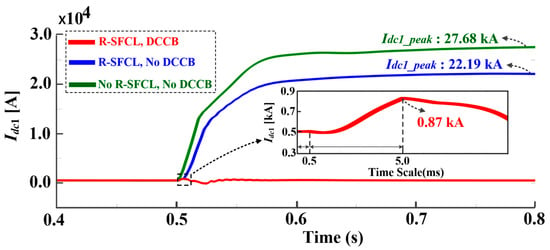
Figure 11.
Comparison of Idc1 waveforms for R-FCL and DCCB applications.
6. Conclusions
In this paper, we propose a Bi-LSTM-based fault diagnosis scheme to improve the accuracy and diagnosis time of MVDC systems. Switch-level modeling of the MVDC system is performed to generate training data for the proposed fault diagnosis framework. The fault currents are mi×tigated using an R-FCL and a DCCB in the model of the MVDC system. The voltage and current measured from a DC line and AC grid are extracted as transient characteristics in the time domain using the DWT. Based on the extracted data, the Bi-LSTM algorithm is used to accurately diagnose and classify the fault type and location. To verify the accuracy of the proposed fault diagnosis scheme, various training and testing scenarios are applied to each fault type in the four-terminal MVDC system. As a result, our scheme shows a higher accuracy and a faster diagnosis time compared to those of the fault diagnosis schemes using existing AI algorithms, such as the CNN and LSTM. Therefore, its effectiveness is verified. In addition, the stability of the system is confirmed by reducing the fault current by comparing the Idc peak value according to the presence or absence of the R-FCL and the DCCB. Future work will focus on verifying the algorithm proposed in this paper by configuring hardware-in-the-loop simulations (HILS) considering noise conditions. In addition, the accuracy and diagnosis time of the proposed algorithm will be verified with different training and test systems.
Author Contributions
J.-S.L. and H.C. conceived and designed the experiments; J.-S.L. and H.C., D.K. wrote the paper; J.H. performed data analysis and critically revised the manuscript for important intellectual content. All authors have read and agreed to the published version of the manuscript.
Funding
This work was funded by the Korea Institute of Energy Technology Evaluation and Planning (KETEP) and the Ministry of Trade, Industry & Energy (MOTIE) of the Republic of Korea (No. 20224000000490).
Data Availability Statement
The original contributions presented in the study are included in the article, further inquiries can be directed to the corresponding author.
Conflicts of Interest
The authors declare no conflict of interest.
Correction Statement
This article has been republished with a minor correction to the front note. This change does not affect the scientific content of the article.
Abbreviations
The following abbreviations are used in this manuscript:
| Wavelet Function | |
| m | Scale Parameter |
| n | Shift Parameter |
| Approximation Coefficient | |
| Detail Coefficient | |
| Scaling Coefficients | |
| Reconfigured Coefficient | |
| Scaling Coefficient | |
| Forget Gate | |
| Input Gate | |
| Update Cell | |
| New Cell | |
| Output Gate | |
| Forget Gate Learnable Weights | |
| Input Gate Learnable Weights | |
| Cell Learnable Weights | |
| Output Gate Learnable Weights | |
| Forget Gate Biases | |
| Input Gate Biases | |
| Cell Biases | |
| Output Gate Biases | |
| Block’s Output | |
| Feature Vector Input |
References
- Doerry, N.; Amy, J.; Krolick, C. History and the status of electric ship propulsion, integrated power systems, and future trends in the U. S. Navy. Proc. IEEE 2015, 103, 2243–2251. [Google Scholar] [CrossRef]
- Jin, Z.; Meng, L.; Guerrero, J.M.; Han, R. Hierarchical control design for a shipboard power system with DC distribution and energy storage aboard future more-electric ships. IEEE Trans. Ind. Inform. 2018, 14, 703–714. [Google Scholar] [CrossRef]
- Yuan, C.; Haj-ahmed, M.A.; Illindala, M.S. Protection strategies for medium-voltage direct-current microgrid at a remote area mine site. IEEE Trans. Ind. Appl. 2015, 51, 2846–2853. [Google Scholar] [CrossRef]
- Nougain, V.; Mishra, S.; Jena, S.S. Resilient protection of medium voltage DC microgrids against cyber intrusion. IEEE Trans. Power Del. 2022, 37, 960–971. [Google Scholar] [CrossRef]
- Gowaid, I.A.; Adam, G.P.; Massoud, A.M.; Ahmed, S.; Williams, B.W. Hybrid and modular multilevel converter designs for isolated HVDC-DC converters. IEEE J. Emerg. Sel. Top. Power Electron. 2018, 6, 188–202. [Google Scholar] [CrossRef]
- Xu, J.; Zhao, X.; Han, N.; Liang, J.; Zhao, C. A thyristor-based DC fault current limiter with inductor inserting-bypassing capability. IEEE J. Emerg. Sel. Top. Power Electron. 2019, 7, 1748–1757. [Google Scholar] [CrossRef]
- Chaudhuri, N.; Chaudhuri, B.; Majumder, R.; Yazdani, A. Multi-Terminal Direct-Current Grids: Modeling, Analysis, and Control; Wiley: Hoboken, NJ, USA, 2014; Chapter 6. [Google Scholar]
- Jiang, S.; Fan, C.; Huang, N.; Zhu, Y.; He, M. A fault location method for DC lines connected with DAB terminal in power electronic transformer. IEEE Trans. Power Del. 2019, 34, 301–311. [Google Scholar] [CrossRef]
- Makkieh, A.; Psaras, V.; Peña-Alzola, R.; Tzelepis, D.; Emhemed, A.A.S.; Burt, G.M. Fault location in DC microgrids based on a multiple capacitive earthing scheme. IEEE J. Emerg. Sel. Top. Power Electron. 2021, 9, 2550–2559. [Google Scholar] [CrossRef]
- Hunter, L.C.; Booth, C.D.; Egea-Alvarez, A.; Dyśko, A.; Finney, S.J.; Junyent-Ferré, A. A New Fast-Acting Backup Protection Strategy for Embedded MVDC Links in Future Distribution Networks. IEEE Trans. Power Del. 2021, 36, 861–869. [Google Scholar] [CrossRef]
- Baran, M.E.; Mahajan, N.R. Overcurrent protection on voltage-source-converter-based multiterminal DC distribution systems. IEEE Trans. Power Del. 2007, 22, 406–412. [Google Scholar] [CrossRef]
- Fletcher, S.D.A.; Norman, P.J.; Galloway, S.J.; Crolla, P.; Burt, G.M. Optimizing the roles of unit and non-unit protection methods within DC microgrids. IEEE Trans. Smart Grid 2012, 3, 2079–2087. [Google Scholar] [CrossRef]
- Sharma, N.K.; Samantaray, S.R.; Bhende, C.N. VMD-Enabled Current-Based Fast Fault Detection Scheme for DC Microgrid. IEEE Syst. J. 2022, 16, 933–944. [Google Scholar] [CrossRef]
- Sneath, J.; Rajapakse, A.D. Fault detection and interruption in an earthed HVDC grid using ROCOV and hybrid DC breakers. IEEE Trans. Power Del. 2016, 31, 973–981. [Google Scholar] [CrossRef]
- Monadi, M.; Gavriluta, C.; Luna, A.; Candela, J.I.; Rodriguez, P. Centralized protection strategy for medium voltage DC microgrids. IEEE Trans. Power Del. 2017, 32, 430–440. [Google Scholar] [CrossRef]
- Emhemed, A.A.; Fong, K.; Fletcher, S.; Burt, G.M. Validation of fast and selective protection scheme for an LVDC distribution network. IEEE Trans. Power Del. 2017, 32, 1432–1440. [Google Scholar] [CrossRef]
- Zain Yousaf, M.; Liu, H.; Raza, A.; Baber Baig, M. Primary and Backup Fault Detection Techniques for Multi-Terminal HVDC Systems: A Review. IET Gener. Trans. Distrib. 2020, 14, 5261–5276. [Google Scholar] [CrossRef]
- Yousaf, M.Z.; Singh, A.R.; Khalid, S.; Bajaj, M.; Kumar, B.H.; Zaitsev, I. Bayesian-Optimized LSTM-DWT Approach for Reliable Fault Detection in MMC-Based HVDC Systems. Sci. Rep. 2024, 14, 17968. [Google Scholar] [CrossRef]
- Yousaf, M.Z.; Khalid, S.; Tahir, M.F.; Tzes, A.; Raza, A. A Novel DC Fault Protection Scheme Based on Intelligent Network for Meshed DC Grids. Int. J. Electr. Power Energy Syst. 2023, 154, 109423. [Google Scholar] [CrossRef]
- Christopher, E.; Sumner, M.; Thomas, D.W.; Wang, X.; de Wildt, F. Fault location in a zonal DC marine power system using active impedance estimation. IEEE Trans. Ind. Appl. 2013, 49, 860–865. [Google Scholar] [CrossRef]
- Zhang, N.; Kezunovic, M. Transmission line boundary protection using wavelet transform and neural network. IEEE Trans. Power Del. 2007, 22, 859–869. [Google Scholar] [CrossRef]
- Li, H.; Li, W.; Luo, M.; Monti, A.; Ponci, F. Design of smart MVDC power grid protection. IEEE Trans. Instrum. Meas. 2011, 60, 3035–3046. [Google Scholar] [CrossRef]
- Merlin, V.L.; Santos, R.C.D.; Le Blond, S.; Coury, D.V. Efficient and robust ANN-based method for an improved protection of VSC HVDC systems. IET Renew. Power Gener. 2018, 12, 1555–1562. [Google Scholar] [CrossRef]
- Yang, Q.Q.; Le Blond, S.; Aggarwal, R.; Wang, Y.W.; Li, J.W. New ANN method for multi-terminal HVDC protection relaying. Electr. Power Syst. Res. 2017, 148, 192–201. [Google Scholar] [CrossRef]
- Li, W.; Monti, A.; Ponci, F. Fault detection and classification in medium voltage DC shipboard power systems with wavelets and artificial neural networks. IEEE Trans. Instrum. Meas. 2014, 63, 2651–2665. [Google Scholar] [CrossRef]
- Hossam-Eldin, A.; Lotfy, A.; Elgamal, M.; Ebeed, M. Artificial intelligence-based short-circuit fault identifier for MT-HVDC systems. IET Gener. Transm. Distrib. 2018, 12, 2436–2443. [Google Scholar] [CrossRef]
- Luo, G.M.; Yao, C.Y.; Tan, Y.J.; Liu, Y.L. Transient signal identification of HVDC transmission lines based on wavelet entropy and SVM. J. Eng. 2019, 2019, 2414–2419. [Google Scholar] [CrossRef]
- Han, Y.; Qi, W.; Ding, N.; Geng, Z. Short-time wavelet entropy integrating improved LSTM for fault diagnosis of modular multilevel converter. IEEE Trans. Cybern. 2022, 52, 7504–7512. [Google Scholar] [CrossRef] [PubMed]
- Yousaf, M.Z.; Liu, H.; Raza, A.; Mustafa, A. Deep Learning-based Robust DC Fault Protection Scheme for Meshed HVDC Grids. CSEE J. Power Energy Syst. 2023, 9, 2423–2434. [Google Scholar]
- Wang, Y.; Zheng, D.; Jia, R. Fault Diagnosis Method for MMC-HVDC Based on Bi-GRU Neural Network. Energies 2022, 15, 994. [Google Scholar] [CrossRef]
- Li, J.; Song, G.; Yan, J.; Li, Y.; Xu, Z. Data-Driven Fault Detection and Classification for MTDC Systems by Integrating HCTSA and Softmax Regression. IEEE Trans. Power Del. 2022, 37, 893–904. [Google Scholar] [CrossRef]
- Pourfaraj, A.; Iman-Eini, H.; Bazyar, S.; Ahmadi, S.; Asadi, E.; Langwasser, M.; Liserre, M. A Fault Detection Algorithm Based on Artificial Neural Network Threshold Selection in Multi-Terminal DC Grids. IEEE Trans. Power Del. 2023, 38, 2510–2520. [Google Scholar] [CrossRef]
- Pérez-Molina, M.J.; Larruskain, D.M.; Eguía, P.; Santiago, V.V. Local Derivative-Based Fault Detection for HVDC Grids. IEEE Trans. Ind. Appl. 2022, 58, 1521–1530. [Google Scholar] [CrossRef]
- Kalcon, G.O.; Adam, G.P.; Anaya-Lara, O.; Lo, S.; Uhlen, K. Small-Signal Stability Analysis of Multi-Terminal VSC-Based DC Transmission Systems. IEEE Trans. Power Syst. 2012, 27, 1818–1830. [Google Scholar] [CrossRef]
- Tan, X.; Ren, L.; Liang, S.; Tang, Y.; Xu, Y.; Shi, J.; Li, Z. Analysis of R-SFCL with Shunt Resistor in MMC-HVDC System Using Novel R-Q Method. IEEE Trans. Appl. Supercond. 2020, 30, 1–5. [Google Scholar] [CrossRef]
- Jiang, Z.; Yu, Z.; Zhou, Y.; Liu, S.; Li, X.; Pan, R. Application of Resistance SFCL in MTDC Grid With Reclosing Protection Strategy. IEEE Trans. Appl. Supercond. 2021, 31, 1–5. [Google Scholar] [CrossRef]
- Ryan, D.J.; Torresan, H.D.; Bahrani, B. A Bidirectional Series Z-Source Circuit Breaker. IEEE Trans. Power. Electron. 2018, 33. [Google Scholar] [CrossRef]
- Meyer, J.M.; Rufer, A. A DC hybrid circuit breaker with ultrafast contact opening and integrated gate-commutated thyristors (IGCTS). IEEE Trans. Power Del. 2006, 21, 646–651. [Google Scholar] [CrossRef]
- Jayamaha, D.K.J.S.; Lidula, N.W.A.; Rajapakse, A.D. Wavelet-multi resolution analysis based ANN architecture for fault detection and localization in DC microgrids. IEEE Access 2019, 7, 145371–145384. [Google Scholar] [CrossRef]
- Schmidhuber, J. Deep learning in neural networks: An overview. Neural Netw. 2015, 61, 85–117. [Google Scholar] [CrossRef]
- Baker, M.; Fard, A.Y.; Althuwaini, H.; Shadmand, M.B. Real-Time AI-Based Anomaly Detection and Classification in Power Electronics Dominated Grids. IEEE J. Emerg. Sel. Top. Ind. Electron. 2023, 4, 549–559. [Google Scholar] [CrossRef]
- Xu, P.; Wang, C.; Ye, J.; Ouyang, T. State-of-Charge Estimation and Health Prognosis for Lithium-Ion Batteries Based on Temperature-Compensated Bi-LSTM Network and Integrated Attention Mechanism. IEEE Trans. Indus. Elec. 2024, 71, 5586–5596. [Google Scholar] [CrossRef]
- Zheng, L.; Jia, K.; Yang, B.; Bi, T.; Yang, Q. Singular value decomposition based pilot protection for transmission lines with converters on both ends. IEEE Trans. Power Del. 2022, 37, 2728–2737. [Google Scholar] [CrossRef]
Disclaimer/Publisher’s Note: The statements, opinions and data contained in all publications are solely those of the individual author(s) and contributor(s) and not of MDPI and/or the editor(s). MDPI and/or the editor(s) disclaim responsibility for any injury to people or property resulting from any ideas, methods, instructions or products referred to in the content. |
© 2024 by the authors. Licensee MDPI, Basel, Switzerland. This article is an open access article distributed under the terms and conditions of the Creative Commons Attribution (CC BY) license (https://creativecommons.org/licenses/by/4.0/).