Abstract
This article provides an overview of control algorithms for grid-connected converters in renewable energy systems, demonstrating their relevance and potential for further research. A common issue among authors of scientific works is the lack of a wide range of conducted research. Often, the results showing the operation of the developed algorithms in transient states or under abnormal supply conditions (such as asymmetries and distortions) are missing. This significantly reduces the ability to compare developed solutions, making it difficult to choose the appropriate control method for future research. The article suggests which control algorithm for power converters is best suited for research considering various factors.
1. Introduction
The multidimensional and dynamic development of material, information, and production technologies enables increasingly efficient utilisation of renewable energy sources [1]. Many experts focus on improving the first stage of electric energy processing, involving direct extraction from solar radiation, wind, or water [2]. Subsequently, the harvested energy is transferred to a DC intermediary voltage circuit through a converter. It is then transformed using an AC/DC grid converter and fed into the power grid [3].
At the AC terminals of the grid converter, a high-frequency rectangular voltage is present, resulting from the switching of transistors according to the applied control algorithm. This type of voltage cannot be directly applied to the terminals of the power grid, which carries a relatively slow-varying, sinusoidal voltage. This necessitates using an additional coupling element to connect the grid converter to the power grid. This additional coupling can be achieved using inductors or a combination of inductors and capacitors. Moreover, these elements play a crucial role in ensuring the quality of electric energy. The switching of transistors within the converter branches generates higher harmonics, which reduce the efficiency of the power electronic device itself and increase transmission losses in the power grid. The aforementioned coupling elements mitigate the negative impact of using converters on the quality of electric energy due to their filtering properties that smooth rapid changes in currents and voltage [4,5].
2. Classification of Voltage Converter Control Methods
The classification presented in Figure 1 does not encompass all the known groups of AC/DC grid converter control methods described in the literature. However, the depicted groups highlight the fundamental differences from other well-known and practically applied control methods.
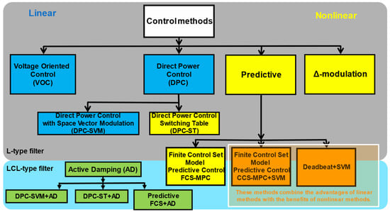
Figure 1.
Classification of voltage converter control methods.
Selected methods used to control voltage converters can be classified in two ways. The first way divides the methods into those easily implementable for control systems of converters coupled with the power grid using an L-type filter and those that enable control of converters coupled with the power grid using an LCL filter. The second classification distinguishes between linear methods, marked with blue block backgrounds in Figure 1, and nonlinear methods, indicated by yellow backgrounds.
The simplest method of filtering the currents generated in the network is to use an L-type filter. This method of coupling the converter to the power grid offers several advantages. Among these are the absence of the filter’s resonant frequency and ease of use with most converter control methods (both linear and nonlinear).
Linear methods generally exhibit high accuracy in converters’ static operating state. However, due to the use of linear PI controllers in the regulation loop, their dynamic response is limited and does not allow full utilisation of the controlled object’s dynamics. Conversely, nonlinear methods enable the utilisation of the controlled object’s maximum dynamics during transient states. Additionally, they are characterised by a spread spectrum of generated grid current, which complicates the selection of a coupling filter between the converter and the power grid.
Using LCL input filters ensures a higher level of attenuation of higher harmonics. However, combining inductive and capacitive elements creates two resonance circuits, precluding linear PI control methods and basic nonlinear methods for controlling the converter. Active Damping algorithms are applied to eliminate the filter’s resonant harmonics in linear methods and, thus, enable their use in converters coupled with the power grid via an LCL filter. The effectiveness of these methods is low under distorted supply voltage conditions.
Some methods combine the advantages of linear algorithms with those of nonlinear methods. Examples include the FCS MPC (Finite Control Set Model Predictive Control) method, which features the application of a single output voltage vector to the AC terminals of the converter within one control period; the predictive CCS MPC (Continuous Control Set Model Predictive Control) method, which can apply several vectors to the AC terminals within one control period, and the Deadbeat method. By utilising the mathematical model of the converter with an L or LCL filter, these methods ensure high-quality regulation of the generated current under various supply conditions. The yellow-blue background signifies that these methods possess the advantages of both linear and nonlinear methods, which will be described in greater detail in the following sections of the article.
3. Overview of Key Features of Selected Control Methods
3.1. Control Methods Suitable Exclusively for L-Type Filter
3.1.1. Voltage-Oriented Control
On the grey background of Figure 1, examples of control methods suitable for converters coupled to the power grid solely through an inductive element are listed. Among the linear methods, marked with a blue background in the blocks in Figure 1, the VOC (Voltage Oriented Control) and DPC SVM (Direct Power Control with Space Vector Modulation) methods are included. The essence of the VOC method lies in the regulation of transformed information about the generated grid currents into two orthogonal components, x and y, in a rotating reference frame xy aligned with the power grid voltage vector (Figure 2) [6,7,8]. The proper process of current component regulation is typically executed using two linear proportional–integral (PI) controllers, with one controller for the x and one for the y component. The control signals from the PI controllers are the reference voltage signals in the synchronously rotating xy reference frame. These signals undergo a transformation from the xy reference frame to the natural abc frame, and the resulting three signals are fed into the modulators, which directly generate the control signals for the transistors of the grid converter. Practical implementations of the VOC method exhibit advantages and disadvantages, primarily stemming from using the modulator. The benefits include a low total harmonic distortion (THD) coefficient of the shaped grid current and a constant switching frequency of the transistors. However, it is challenging to select the controller settings in a way that achieves high-quality regulation indicators both in steady-state and transient conditions (e.g., during a step change in the set value of one of the regulated current components) [9].
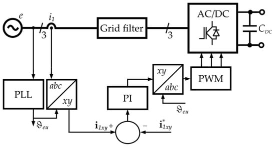
Figure 2.
Example block diagram of VOC control algorithm.
3.1.2. Direct Power Control with Space Vector Modulation
On the other hand, the DPC SVM method involves direct control of the active and reactive power delivered to or drawn from the power grid [10,11]. This regulation uses linear controllers (e.g., PI controllers) and modulators (Figure 3). The structure of this control system is simple and very similar to that of the VOC method. Both methods essentially share the same advantages and disadvantages regarding the quality of regulation results.
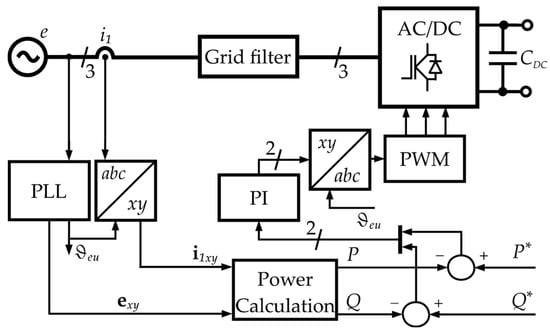
Figure 3.
Example block diagram of DPC control algorithm.
3.1.3. Δ-Modulation
In contrast, moving to the group of nonlinear methods, marked in yellow in Figure 1, it is worth noting that the simplest nonlinear control method to implement using microprocessors is Δ-modulation [12]. The regulation process occurs in the natural three-phase abc system, where the actual phase currents are compared with the set value in comparators (Figure 4) [13,14]. This method is characterised by good dynamic response in transient states and allows independent current regulation in each phase. However, this control method is associated with an increased total harmonic distortion (THD) of the current. The current spectrum is spread out due to the variable switching frequency.
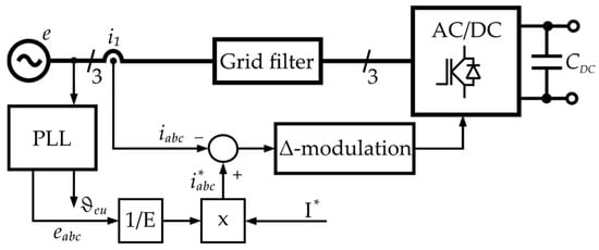
Figure 4.
Example block diagram of the Δ-modulation control algorithm.
3.1.4. Direct Power Control with Switching Table
The DPC ST (Direct Power Control with Switching Table) method employs comparators, and a switching table in the control paths of active and reactive power exchanged with the power grid (Figure 5) [15,16,17]. Compared to linear methods, this control system structure ensures excellent transient state regulation properties. Improving the regulation indicators in steady states, such as current ripple, requires high control and measurement system operating frequencies. The shaped current using DPC-ST methods is resistant to distorted supply voltage in the power grid [18].
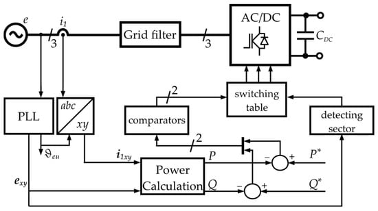
Figure 5.
Example block diagram of DPC with switching table control algorithm.
3.2. Control Methods Originally Designed for L-Type Filters Incorporate Additional Active Damping to Adapt These Methods for Use in Systems with LCL Filters
In the discussed control systems, significant inductance values must be used in an L-type filter for adequate filtering, especially compared to an LCL filter with the same total inductance, which offers higher suppression efficiency of higher harmonics. Furthermore, using LCL filters reduces the filter components’ size and cost. An LCL filter circuit contains two resonant circuits. To achieve high-quality regulation, appropriate resonant frequency values must be ensured during the filter design stage, preventing the amplification of harmonics generated by the AC/DC converter. For this reason, nonlinear control methods with variable switching frequencies are more challenging to implement in a converter system with an LCL filter. Linear controllers in linear methods exhibit good regulation effectiveness with steady or slowly varying signals, i.e., at frequencies significantly lower than the grid voltage frequency. In contrast, the resonant frequencies associated with the resonant circuits of the LCL input filter are rapidly varying signals in the rotating reference frame. Such signals significantly degrade regulation effectiveness in systems with linear controllers. The literature describes developing DPC and VOC methods using active damping (AD) strategies [19,20,21]. This strategy involves damping current components to the control signals to suppress resonant harmonics associated with an LCL filter (Figure 6). The effectiveness of using AD strategies significantly decreases with distorted grid voltage, requiring more complex methods [22]. Predictive algorithms are accessible from this drawback.
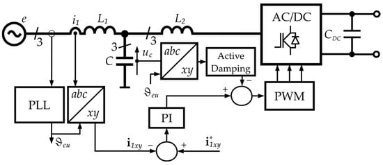
Figure 6.
Example block diagram of VOC with active damping control algorithm.
3.3. Predictive Control Methods for Use with L or LCL-Type Filter
The predictive methods group is the last group of control methods visible in Figure 1, whose dynamic development is further supported by the rapid advancement of microprocessor technology. Available microprocessors are rapidly gaining increased computational power. This directly translates into the ability to process more calculations within a single control period. The group of predictive methods is fundamentally divided into three subgroups: FCS-MPC, CCS-MPC, and Deadbeat (DB). All mentioned control methods are based on equations describing the mathematical model of the converter connected to the grid via an L or LCL filter.
Examples of predictive methods applied to power electronics converter control include [23,24]. They are characterised by simplicity and intuitive control design principles, high dynamic response in transient states, and the ability to control multiple physical quantities simultaneously. They also benefit from the extended prediction horizon option [25]. In optimising the selection of the appropriate vector, parameters related to the sampling period and/or the number of transistors switching can reduce the switching frequency [26]. Besides using model equations to determine the control vector, various configurations of additional feedback in the control system are being tested [27]. An important aspect, often overlooked during algorithm design, is its sensitivity to parameter mismatches in the model compared to their real counterparts. Lack of precise information about the controlled object prevents accurate prediction and, thus, the correct vector selection for the next control period [28]. Model imperfections become particularly significant in the steady-state operation of the regulated system, where maintaining a minimal ripple of regulated quantity is desired. Factors such as temperature and the ageing of electrical/electronic components affect the value of real parameters [29]. In power electronics, the influence of magnetic material saturation cannot be ignored [30]. Compensating for errors due to model imperfections is a central topic in the work of many researchers, e.g., [31]. Examples of developed methods for compensating model parameter estimation imperfections include using integration functions of steady-state error and applying this information to modify equation coefficients [32], as well as employing adaptive functions that allow for improved regulation parameters in both static and dynamic states [33,34].
3.3.1. Finite Control Set Model Predictive Control
The FCS-MPC (Finite Control Set Model Predictive Control) method involves applying one voltage vector to the AC terminals of the grid converter at the end of the control period [35,36,37,38]. Figure 7 shows an example diagram of such a control method. The selection of the optimal voltage vector is based on analysing a defined cost function for each available vector configuration. The cost function aims to enable parallel regulation of one or more physical quantities in the system [39]. The cost function result is calculated as many times as there are available voltage vectors for the converter. The high flexibility in designing the cost function, in terms of the quantities used for calculations and scaling factors, allows for almost infinite modification of the ongoing regulation process [40]. Methods from this group combine the advantages and disadvantages of linear and nonlinear methods, i.e., they exhibit high dynamics in transient states. In contrast, in steady states, they offer low current ripple coefficients [26]. A significant drawback of methods belonging to this group is the spread of the current spectrum due to variable switching frequency [41]. This fact effectively complicates the proper selection of coupling filter parameters to minimise the impact of voltage converters on the quality of the power grid’s electrical parameters. Methods with a so-called continuous control set (CCS) were developed to eliminate the identified drawback of FCS-MPC methods.
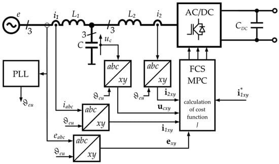
Figure 7.
Example block diagram of FCS MPC control algorithm.
3.3.2. Deadbeat
The predictive principles of DB algorithms use the equations of the controlled object [42,43,44]. The calculations aim to determine the resultant voltage vector at the AC terminals of the converter, which will compensate the controlled variable error to zero within one control period. The voltage vector, determined based on the equations of the controlled object, is reproduced using a modulator (Figure 8). This results in a constant switching frequency, facilitating the design of the coupling filter between the converter and the grid, especially the LCL filter, which may have undesirable effects due to its resonant frequencies. Using a modulator offers the possibility of using several converter vectors within one control period, allowing the shaping of any voltage vector at the AC terminals of the grid converter. As long as the modulator operates within the active modulation area, i.e., in static states and minor transients, small ripple values of the controlled variable are obtained. However, when a sudden and significant change occurs in the control system, the modulator exits the active modulation range, and a single vector is applied to the AC terminals of the converter for the entire control period. This enables the control system’s dynamic and swift response to significant changes in the regulated system parameters.
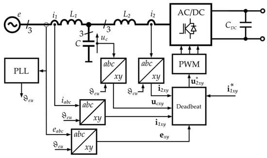
Figure 8.
Example block diagram of Deadbeat controller.
3.3.3. Continuous Control Set Model Predictive Control
Another control group is classified as CCS MPC (Figure 9) [45,46,47]. All the information in the above paragraph concerning the DB method is also valid for CCS MPC algorithms. The distinguishing element of CCS MPC algorithms from DB algorithms is using a cost function [48]. As with FCS MPC algorithms, the cost function allows simultaneous control of one or more variables. The influence of individual model parameters on the target vector to be recreated can be controlled using weighting factors assigned to specific quantities in the control system. It should be noted that correctly selected weighting factors in the cost function should bring the controlled quantity to the target value at the end of the considered control period. Hence, there is a high similarity between DB control methods and CCS MPC methods [49]. Both DB and CCS MPC methods have many advantages in both static and transient states of control. Although they require powerful computing units, using the modulator block extends the time between data acquisitions and iterations of the control algorithm while maintaining a constant and higher switching frequency than the measurement system’s operating frequency [50].
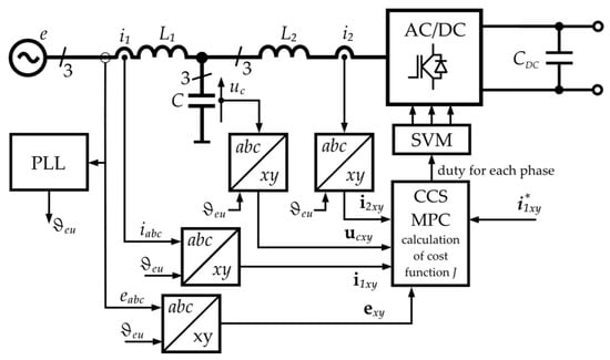
Figure 9.
Example of block diagram CCS MPC with active damping control algorithm.
CCS MPC methods have the advantages of both linear and nonlinear methods. For this reason, they are widely used in various applications, as extensively documented in the scientific literature. The authors of [51,52] present the application of CCS MPC methods in control systems for permanent magnet synchronous motors. In contrast, the use of CCS MPC in controlling induction motors is given in [51,53,54]. The infinite number of controls has also been utilised in DC-DC converters, as demonstrated by the authors in [55,56,57,58]. On the other hand, refs. [59,60] presents the application of the discussed group of methods in matrix converters. Among the applications of CCS MPC methods are also active filters [61,62] and rectifiers [46,48]. The scientific literature also includes examples of using CCS MPC in controlling grid-connected current converters [47].
4. Comprehensiveness and Completeness of Scientific Research
Considering that electricity generation is associated with various types of devices that convert renewable energy into electrical energy and numerous kinds of devices that convert electrical energy with specific parameters into electrical energy with different parameters (e.g., DC-AC conversion), it is crucial to select appropriate control algorithms for power electronic devices carefully. The first significant factor is the nature of the renewable energy source and the direct converter of this energy into electrical energy. This determines the rate of changes in the amount of delivered energy, which can vary with a time constant ranging from a fraction of a second to a minute. This directly influences the selection of regulator settings in the control loops of the converter to ensure the best compromise between the required dynamics and the highest accuracy in steady-state regulation. It must be noted that specific control algorithms are entirely vulnerable to significant disturbances occurring in the power grid and are particularly sensitive to the supply voltage distortion. When a grid-connected converter is connected to a power supply with distorted voltage, there is a possibility that the shaped grid current may not meet the quality requirements regarding harmonic content and may not achieve a steady-state error of zero in steady states. This is extremely important from the perspective of a power grid with high penetration of microgeneration based on renewable energy sources.
Various positions in the literature describe the different topologies of converters combined with various input filters. Unfortunately, a common practice among the authors of scientific works is the lack of a broad spectrum of conducted research. Most often, the results presenting the operation of the developed algorithms in transient states or under abnormal supply conditions (i.e., asymmetries, distortions) are missing. This significantly reduces the ability to compare developed solutions. Therefore, Table 1 compares selected literature positions describing representatives of the control algorithms classified in Section 3. It details the features that should be investigated when proposing new control methods. If the literature position is highlighted in grey, it means that the publication does not present the results of the algorithm feature described in the left column of the given row.

Table 1.
List of types of experiments regarding grid converter control algorithms.
5. Applications and Research Directions
The numerous examples of the application of predictive methods presented so far prove their relevance and the need for further research [63,64,65,66,67]. The authors [64] developed a different control strategy to maintain good-quality parameters of the controlled grid current. They created individual models for various supply conditions deviating from sinusoidal, symmetrical three-phase voltage. Each model variant includes additional calculations related to complementary equations and performing discrete Fourier transforms for selected frequencies. In terms of the overall structure of the presented model, this is a highly complex solution.
An interesting example of a prediction algorithm is the creation of hybrid methods combining FCS MPC and CCS MPC in one control algorithm [66]. The proposed control aims to minimise switching losses without significantly losing the ability to reproduce a sinusoidal grid current by switching between the two types of control. As highlighted by the authors, such a solution has a problem with excessively long computation times, which practically excludes the possibility of implementing the proposed solution in practical applications.
One development direction of CCS algorithms discusses the control of grid-connected converters using an LCL filter and cooperating with renewable energy sources. Models of the controlled grid converter are extended with equations describing, for example, a converter receiving electrical energy from photovoltaic panels [67]. Therefore, the control system includes additional components related to maximising the power received from photovoltaic panels, which affects the functioning of the entire control system.
A significantly more significant number of publications in the field of predictive methods does not mean that linear control methods are not being developed. For example, the article [68] presents a Voltage-Oriented Control (VOC) strategy for LCL-filtered grid-connected bidirectional AC-DC converters in the context of renewable energy sources. Key achievements include the introduction of observer-based active damping to mitigate LCL filter resonance, eliminating the need for passive damping components and reducing power losses. The control scheme, validated through real-time software-in-the-loop (RT-SIL) simulations, demonstrated compliance with international power quality standards.
The objective of article [69] was to develop a Direct Power Predictive Control (DPPC) for a single-stage PV system connected to the grid through a current source inverter. The study demonstrated the effectiveness of DPPC in tracking power references for PV systems, with the ability to control reactive power independently from active power. Single-state topologies were emphasised over two-stage topologies for CSI control in PV applications.
It is essential to highlight a fundamental flaw associated with the mathematical description of linear methods. Small-signal models are frequently used for method analysis, based on which frequency characteristics are determined. These frequency characteristics are then used to assess dynamics and stability of control systems. The primary issue to emphasise is that most linear methods utilise Pulse Width Modulators, Space Vector Modulators, or more complex modulation techniques. When using small-signal models, it is approximated that the modulator acts as an amplifying component with a time delay. Unfortunately, this is not a correct approach due to the differing dynamics of vector interactions at the AC terminals of the converter on the controlled network filter system and the power grid. The issue of vector interactions on the converter system with an L-filter should begin with the schematic of such a system (see Figure 10).
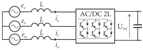
Figure 10.
The schematic of an AC/DC converter with a passive L-type grid filter.
The fundamental executive component of an AC/DC and DC/AC converter is a three-phase, two-level transistor bridge, which connects each AC terminal to the potential +UDC or −UDC, depending on the state of the individual switches. Depending on the selected configuration of conducting switches, in the stationary αβ coordinate system, the voltage at the UVW terminals can be described by the following relationship:
where
—are the space vectors of the converter voltage at the AC terminals, determined by the configuration of the conducting switches of the converter, which can take states dependent on the coefficient n = from 1 to 6,
“0”—are the zero vectors formed by the converter when all three phases of the load are connected to one potential (+UDC or −UDC), denoted as “0”.
The converter-power grid system (Figure 10) is described by vector Equation (1) in the stationary xy coordinate system:
where
eαβ—is the grid voltage vector in the stationary αβ coordinate system,
iαβ—is the grid current vector,
uαβ—is the voltage vector shaped by the AC/DC converter, and
L—is the inductance of the grid inductors.
Transitioning to the rotating coordinate system makes all quantities related to the power grid (e.g., voltage e, current ixy) constant in the steady state. For convenience in further analysis, Equation (2) is transformed to the xy coordinate system rotating with the grid voltage angular frequency ω:
where
exy—is the grid voltage vector in the stationary xy coordinate system,
ixy—is the grid current vector, and
uxy—is the voltage vector on AC terminals of the AC/DC converter, dependent on the state of the conducting switches.
The task of the current control algorithm is to maintain the grid current ixy with the slightest possible deviation from the reference value. Hence, it can be assumed that the control error is defined as i*xy − ixy equals 0. Equation (3) in a steady state can be visualised, as shown in Figure 11.
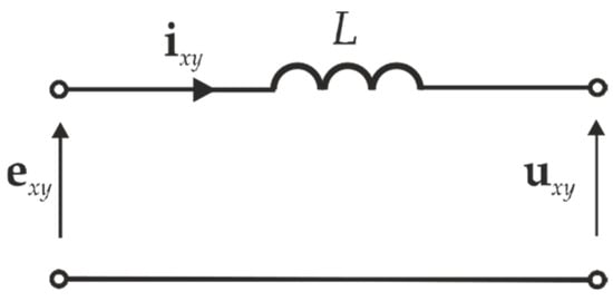
Figure 11.
Equivalent circuit diagram of an AC/DC converter with an L filter in a rotating coordinate system with grid pulsation ω.
The direction and rate of change of the grid current vector are determined by the derivative of this current, which, after considering relationship (3), takes the following form:
where
u*xy—is the reference vector of the first harmonic of the converter’s output voltage, which enforces the grid current to flow close to the reference value, and
du—is the direction vector proportional to the derivative of the current.
Based on the above relationships, the direction of the generated current in the xy plane depends on the difference between the vectors u*xy and uxy. The situation is depicted in the Figure 12.
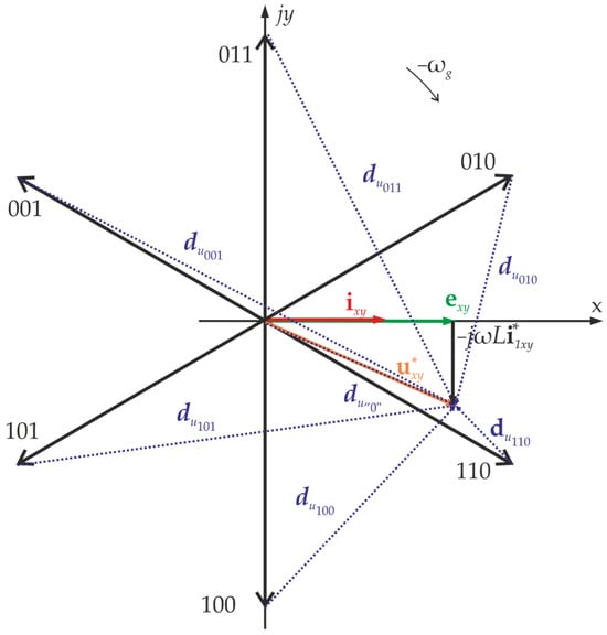
Figure 12.
Proportional vectors du to the current derivatives in the rotating xy coordinate system.
According to (6), the current derivative vectors di are proportional to vectors du. Hence, Figure 13 shows the influence of individual converter’s voltage vectors on a controlled grid current.
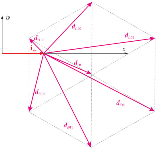
Figure 13.
Current derivative vectors di in the rotating xy coordinate system.
As can be observed, the increase in the x component of the grid current vector occurs at a completely different rate compared to the decrease of the same component. The longer the vectors di, the faster the controlled current changes. Vectors di101 and di001 or di‘0’ should be used to increase the x-component value of the grid. Conversely, to decrease the x-component value of the grid current vector, vectors di110 or di010 should be used. It is important to emphasise that increasing only the x component is impossible in the situation depicted in Figure 13. Applying any converter voltage vector changes the x and y components of the controlled grid current vector. The above information is confirmed by the results of simulation studies where the example of the predictive control method was compared with the example of the linear control method.
A two-level converter model was simulated in the setup shown in Figure 10. A typical VOC structure was chosen for the linear method, with settings adjusted according to the modulus symmetry criterion. The predictive method described in [70] was selected for the nonlinear method. The simulation results are presented in Figure 14 and Figure 15. As can be observed, the predictive method does not exhibit overshoot after changing the setpoint (Figure 14). In both methods, the new setpoint current value is achieved faster when increasing the x component than when decreasing it. In the linear method (Figure 15), it is important to note the larger variations in the y component of the grid current during transient states, which are significantly greater than in the predictive method.
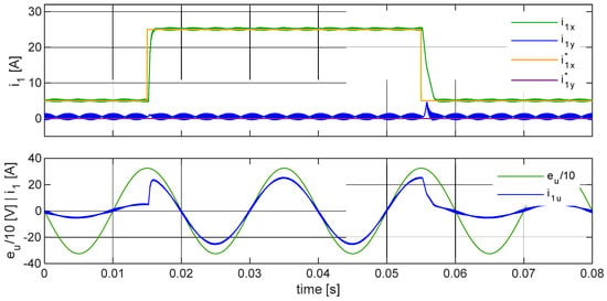
Figure 14.
An example of grid current control with predictive control in a three-phase voltage converter with an L-type grid coupling filter. From the top: set and actual values of grid current vector’s components; waveforms of selected phase voltage and phase current.
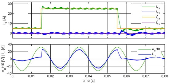
Figure 15.
An example of grid current control with linear control in a three-phase voltage converter with an L-type grid coupling filter. From the top: set and actual values of grid current vector’s components; waveforms of selected phase voltage and phase current.
In the predictive method, the voltage vectors at the AC terminals of the converter, which influence the changes in the individual components of the grid current vectors x and y, are selected considering the dynamics of the grid current changes. Compared to the linear method, this results in shorter times to reach new set values in transient states. This is extremely important, especially in converters dedicated to photovoltaic panels where frequent and significant changes in the amount of electricity fed into the grid can occur, such as those resulting from shading of panels due to cloud cover. Therefore, the future direction for the development of linear methods should involve the creation of alternative small-signal models that account for the different dynamics in increasing and decreasing the shaped current values. Consequently, it becomes clear that universal settings for linear controllers, which guarantee acceptable regulation parameters and minimise overshoot and short regulation time in transient states during positive and negative step change of set values, cannot be applied. This would undoubtedly benefit the stability of the controlled system and shorten regulation times in transient states.
6. Discussion
The literature review indicates that traditional, simpler control methods often present only simulation results and straightforward experimental outcomes. These studies, which focus on linear or non-predictive nonlinear methods, typically exclude experiments that test the control algorithm’s robustness against changes in power supply parameters such as voltage asymmetries and harmonic distortions. This omission is primarily due to the inadequate performance of these control strategies under such conditions. In contrast, predictive control algorithms are frequently evaluated through experimental research rather than simulations. These experiments often reflect real-world conditions, including non-ideal sinusoidal supply voltages and mismatches between the control algorithm’s parameter assumptions and the actual characteristics of the power conversion components. For example, inductance values may vary with different current levels, and filter capacitor capacitance may change due to ageing and temperature effects. Predictive control methods, such as Deadbeat (DB) and Continuous Control Set Model Predictive Control (CCS-MPC), are increasingly popular due to their advanced performance and flexibility. These methods provide several advantages, particularly in systems with numerous small renewable energy generators.
Control algorithms that use a model of the system being controlled can be affected by inaccuracies in the model’s parameters compared to the system’s actual parameters. This difference can cause various problems, including reduced control accuracy, more significant tracking errors, and instability in the control system. Using adaptive methods that can estimate the actual parameter values is essential in minimising or eliminating these issues.
It should be recognised that systems with an L filter and a simple, easy-to-implement algorithm are sufficient for the most straightforward simulations and experimental studies under undistorted conditions. However, investing effort in implementing the most advanced methods using object model equations and prediction is worthwhile when aiming for experimental studies in real conditions. The use of FCS MPC methods is recommended to have efficient control units. Such methods are easy to implement. The available literature provides ready-made cost functions that are ready to use.
7. Conclusions
The article offers an overview of control algorithms for grid-connected converters in renewable energy systems, emphasising the benefits of predictive control methods. Traditional control algorithms, primarily based on linear methods, encounter difficulties managing non-ideal conditions such as voltage asymmetries and harmonic distortions. Although these methods perform adequately in simple scenarios, they encounter challenges in real-world conditions. In contrast, predictive control algorithms provide enhanced performance and robustness, making them well-suited for practical applications. The study presents various applications of predictive methods, including developing intricate models for different supply conditions and utilising hybrid control algorithms to minimise switching losses while optimising grid current quality.
The literature outlines various converter topologies combined with different input filters. However, a key issue lies in the limited range of conducted research. Frequently, results illustrating the operation of the developed algorithms in transient states or under abnormal supply conditions are absent, significantly limiting the capability to compare developed solutions. The study advocates for the broader adoption of predictive control algorithms in renewable energy applications, to achieve more efficient and resilient power conversion systems.
Funding
The research, part of work no. WZ/WE-IA/6/2023 at the Bialystok University of Technology, is financed by a research subsidy provided by the Minister of Education and Science.
Data Availability Statement
The original contributions presented in the study are included in the article, further inquiries can be directed to the corresponding author.
Conflicts of Interest
The author declares no conflicts of interest.
References
- Chen, J.; Kim, M.-H. Review of Recent Offshore Wind Turbine Research and Optimization Methodologies in Their Design. J. Mar. Sci. Eng. 2022, 10, 28. [Google Scholar] [CrossRef]
- Sikorski, A.; Falkowski, P.; Korzeniewski, M. Comparison of Two Power Converter Topologies in Wind Turbine System. Energies 2021, 14, 6574. [Google Scholar] [CrossRef]
- Athari, H.; Niroomand, M.; Ataei, M. Review and Classification of Control Systems in Grid-Tied Inverters. Renew. Sustain. Energy Rev. 2017, 72, 1167–1176. [Google Scholar] [CrossRef]
- Beres, R.N.; Wang, X.; Liserre, M.; Blaabjerg, F.; Bak, C.L. A Review of Passive Power Filters for Three-Phase Grid-Connected Voltage-Source Converters. IEEE J. Emerg. Sel. Top. Power Electron. 2016, 4, 54–69. [Google Scholar] [CrossRef]
- Sosa, J.M.; Escobar, G.; Martínez-Rodríguez, P.R.; Vázquez, G.; Juárez, M.A.; Diosdado, M. Comparative Evaluation of L and LCL Filters in Transformerless Grid Tied Converters for Active Power Injection. In Proceedings of the 2014 IEEE International Autumn Meeting on Power, Electronics and Computing (ROPEC), Ixtapa, Mexico, 5–7 November 2014; pp. 1–6. [Google Scholar]
- Malinowski, M.; Kazmierkowski, M.P.; Trzynadlowski, A. Review and Comparative Study of Control Techniques for Three-Phase PWM Rectifiers. Math. Comput. Simul. 2003, 63, 349–361. [Google Scholar] [CrossRef]
- Fekik, A.; Denoun, H.; Azar, A.T.; Hamida, M.L.; Zaouia, M.; Benyahia, N. Comparative Study of Two Level and Three Level PWM-Rectifier with Voltage Oriented Control. In Proceedings of the International Conference on Advanced Intelligent Systems and Informatics 2018; Hassanien, A.E., Tolba, M.F., Shaalan, K., Azar, A.T., Eds.; Springer International Publishing: Cham, Switzerland, 2019; pp. 40–51. [Google Scholar]
- Al-Ogaili, A.S.; Aris, I.B.; Verayiah, R.; Ramasamy, A.; Marsadek, M.; Rahmat, N.A.; Hoon, Y.; Aljanad, A.; Al-Masri, A.N. A Three-Level Universal Electric Vehicle Charger Based on Voltage-Oriented Control and Pulse-Width Modulation. Energies 2019, 12, 2375. [Google Scholar] [CrossRef]
- Zarif, M.; Monfared, M. Step-by-Step Design and Tuning of VOC Control Loops for Grid Connected Rectifiers. Int. J. Electr. Power Energy Syst. 2015, 64, 708–713. [Google Scholar] [CrossRef]
- Malinowski, M.; Jasinski, M.; Kazmierkowski, M.P. Simple Direct Power Control of Three-Phase PWM Rectifier Using Space-Vector Modulation (DPC-SVM). IEEE Trans. Ind. Electron. 2004, 51, 447–454. [Google Scholar] [CrossRef]
- Zhang, Y.; Liu, J.; Yang, H.; Gao, J. Direct Power Control of Pulsewidth Modulated Rectifiers Without DC Voltage Oscillations Under Unbalanced Grid Conditions. IEEE Trans. Ind. Electron. 2018, 65, 7900–7910. [Google Scholar] [CrossRef]
- Prabhakar, N.; Mishra, M.K. Dynamic Hysteresis Current Control to Minimize Switching for Three-Phase Four-Leg VSI Topology to Compensate Nonlinear Load. IEEE Trans. Power Electron. 2010, 25, 1935–1942. [Google Scholar] [CrossRef]
- Suhara, E.M.; Nandakumar, M. Analysis of Hysteresis Current Control Techniques for Three Phase PWM Rectifiers. In Proceedings of the 2015 IEEE International Conference on Signal Processing, Informatics, Communication and Energy Systems (SPICES), Kozhikode, India, 19–21 February 2015; pp. 1–5. [Google Scholar]
- Holmes, D.G.; Davoodnezhad, R.; McGrath, B.P. An Improved Three-Phase Variable-Band Hysteresis Current Regulator. IEEE Trans. Power Electron. 2013, 28, 441–450. [Google Scholar] [CrossRef]
- Razali, A.M.; Rahman, M.A.; George, G.; Rahim, N.A. Analysis and Design of New Switching Lookup Table for Virtual Flux Direct Power Control of Grid-Connected Three-Phase PWM AC–DC Converter. IEEE Trans. Ind. Appl. 2015, 51, 1189–1200. [Google Scholar] [CrossRef]
- Kulikowski, K.; Sikorski, A. New DPC Look-Up Table Methods for Three-Level AC/DC Converter. IEEE Trans. Ind. Electron. 2016, 63, 7930–7938. [Google Scholar] [CrossRef]
- Zhang, Y.; Qu, C.; Gao, J. Performance Improvement of Direct Power Control of PWM Rectifier Under Unbalanced Network. IEEE Trans. Power Electron. 2017, 32, 2319–2328. [Google Scholar] [CrossRef]
- Falkowski, P.; Kulikowski, K.; Grodzki, R. Predictive and Look-up Table Control Methods of a Three-Level AC-DC Converter under Distorted Grid Voltage. Bull. Pol. Acad. Sciences. Tech. Sci. 2017, 65, 609–618. [Google Scholar] [CrossRef][Green Version]
- Guzman, R.; de Vicuña, L.G.; Morales, J.; Castilla, M.; Miret, J. Model-Based Active Damping Control for Three-Phase Voltage Source Inverters with LCL Filter. IEEE Trans. Power Electron. 2017, 32, 5637–5650. [Google Scholar] [CrossRef]
- Ben Saïd-Romdhane, M.; Naouar, M.W.; Slama-Belkhodja, I.; Monmasson, E. Robust Active Damping Methods for LCL Filter-Based Grid-Connected Converters. IEEE Trans. Power Electron. 2017, 32, 6739–6750. [Google Scholar] [CrossRef]
- Serpa, L.A.; Ponnaluri, S.; Barbosa, P.M.; Kolar, J.W. A Modified Direct Power Control Strategy Allowing the Connection of Three-Phase Inverters to the Grid Through $LCL$ Filters. IEEE Trans. Ind. Appl. 2007, 43, 1388–1400. [Google Scholar] [CrossRef]
- Hanif, M.; Khadkikar, V.; Xiao, W.; Kirtley, J.L. Two Degrees of Freedom Active Damping Technique for $LCL$ Filter-Based Grid Connected PV Systems. IEEE Trans. Ind. Electron. 2014, 61, 2795–2803. [Google Scholar] [CrossRef]
- Guo, L.; Jin, N.; Li, Y.; Luo, K. A Model Predictive Control Method for Grid-Connected Power Converters Without AC Voltage Sensors. IEEE Trans. Ind. Electron. 2021, 68, 1299–1310. [Google Scholar] [CrossRef]
- Karamanakos, P.; Liegmann, E.; Geyer, T.; Kennel, R. Model Predictive Control of Power Electronic Systems: Methods, Results, and Challenges. IEEE Open J. Ind. Applicat. 2020, 1, 95–114. [Google Scholar] [CrossRef]
- Geldenhuys, J.M.C.; du Toit Mouton, H.; Rix, A.; Geyer, T. Model Predictive Current Control of a Grid Connected Converter with LCL-Filter. In Proceedings of the 2016 IEEE 17th Workshop on Control and Modeling for Power Electronics (COMPEL), Trondheim, Norway, 27–30 June 2016; pp. 1–6. [Google Scholar]
- Falkowski, P.; Sikorski, A. Finite Control Set Model Predictive Control for Grid-Connected AC–DC Converters with LCL Filter. IEEE Trans. Ind. Electron. 2018, 65, 2844–2852. [Google Scholar] [CrossRef]
- Panten, N.; Hoffmann, N.; Fuchs, F.W. Finite Control Set Model Predictive Current Control for Grid-Connected Voltage-Source Converters with LCL Filters: A Study Based on Different State Feedbacks. IEEE Trans. Power Electron. 2016, 31, 5189–5200. [Google Scholar] [CrossRef]
- Young, H.A.; Perez, M.A.; Rodriguez, J. Analysis of Finite-Control-Set Model Predictive Current Control with Model Parameter Mismatch in a Three-Phase Inverter. IEEE Trans. Ind. Electron. 2016, 63, 3100–3107. [Google Scholar] [CrossRef]
- Guo, L.; Xu, Z.; Jin, N.; Chen, Y.; Li, Y.; Dou, Z. An Inductance Online Identification Method for Model Predictive Control of V2G Inverter with Enhanced Robustness to Grid Frequency Deviation. IEEE Trans. Transp. Electrif. 2022, 8, 1575–1589. [Google Scholar] [CrossRef]
- Guo, L.; Xu, Z.; Li, Y.; Chen, Y.; Jin, N.; Lu, F. An Inductance Online Identification-Based Model Predictive Control Method for Grid-Connected Inverters with an Improved Phase-Locked Loop. IEEE Trans. Transp. Electrif. 2022, 8, 2695–2709. [Google Scholar] [CrossRef]
- Shen, K.; Zhang, J. Modeling Error Compensation in FCS-MPC of a Three-Phase Inverter. In Proceedings of the 2012 IEEE International Conference on Power Electronics, Drives and Energy Systems (PEDES), Bengaluru, India, 16–19 December 2012; pp. 1–6. [Google Scholar]
- Mendez, R.; Sbarbaro, D.; Espinoza, J. High Dynamic and Static Performance FCS-MPC Strategy for Static Power Converters. In Proceedings of the 2016 IEEE Energy Conversion Congress and Exposition (ECCE), Milwaukee, WI, USA, 18–22 September 2016; pp. 1–7. [Google Scholar]
- Jabbour, N.; Mademlis, C. Online Parameters Estimation and Autotuning of a Discrete-Time Model Predictive Speed Controller for Induction Motor Drives. IEEE Trans. Power Electron. 2019, 34, 1548–1559. [Google Scholar] [CrossRef]
- Yang, Y.; Tan, S.-C.; Hui, S.Y.R. Adaptive Reference Model Predictive Control with Improved Performance for Voltage-Source Inverters. IEEE Trans. Control Syst. Technol. 2018, 26, 724–731. [Google Scholar] [CrossRef]
- Falkowski, P.; Sikorski, A.; Malinowski, M. Finite Control Set Model Predictive Control with Floating Virtual Voltage Vectors for Grid-Connected Voltage Source Converter. IEEE Trans. Power Electron. 2021, 36, 11875–11885. [Google Scholar] [CrossRef]
- Tarisciotti, L.; Zanchetta, P.; Watson, A.; Clare, J.C.; Degano, M.; Bifaretti, S. Modulated Model Predictive Control for a Three-Phase Active Rectifier. IEEE Trans. Ind. Appl. 2015, 51, 1610–1620. [Google Scholar] [CrossRef]
- Scoltock, J.; Geyer, T.; Madawala, U.K. Model Predictive Direct Power Control for Grid-Connected NPC Converters. IEEE Trans. Ind. Electron. 2015, 62, 5319–5328. [Google Scholar] [CrossRef]
- Rodriguez, J.; Kazmierkowski, M.P.; Espinoza, J.R.; Zanchetta, P.; Abu-Rub, H.; Young, H.A.; Rojas, C.A. State of the Art of Finite Control Set Model Predictive Control in Power Electronics. IEEE Trans. Ind. Inform. 2013, 9, 1003–1016. [Google Scholar] [CrossRef]
- Foster, J.G.L.; Pereira, R.R.; Gonzatti, R.B.; Sant’Ana, W.C.; Mollica, D.; Lambert-Torres, G. A Review of FCS-MPC in Multilevel Converters Applied to Active Power Filters. In Proceedings of the 2019 IEEE 15th Brazilian Power Electronics Conference and 5th IEEE Southern Power Electronics Conference (COBEP/SPEC), Santos, Brazil, 1–4 December 2019; pp. 1–6. [Google Scholar]
- Karamanakos, P.; Geyer, T. Guidelines for the Design of Finite Control Set Model Predictive Controllers. IEEE Trans. Power Electron. 2020, 35, 7434–7450. [Google Scholar] [CrossRef]
- Aguirre, M.; Kouro, S.; Rojas, C.A.; Vazquez, S. Enhanced Switching Frequency Control in FCS-MPC for Power Converters. IEEE Trans. Ind. Electron. 2021, 68, 2470–2479. [Google Scholar] [CrossRef]
- Benyoucef, A.; Kara, K.; Chouder, A.; Silvestre, S. Prediction-Based Deadbeat Control for Grid-Connected Inverter with L-Filter and LCL-Filter. Electr. Power Compon. Syst. 2014, 42, 1266–1277. [Google Scholar] [CrossRef]
- He, Y.; Chung, H.S.-H.; Ho, C.N.-M.; Wu, W. Use of Boundary Control with Second-Order Switching Surface to Reduce the System Order for Deadbeat Controller in Grid-Connected Inverter. IEEE Trans. Power Electron. 2016, 31, 2638–2653. [Google Scholar] [CrossRef]
- Cheng, C.; Nian, H.; Wang, X.; Sun, D. Dead-Beat Predictive Direct Power Control of Voltage Source Inverters with Optimised Switching Patterns. IET Power Electron. 2017, 10, 1438–1451. [Google Scholar] [CrossRef]
- Sikorski, A.; Grodzki, R. Predictive Control of the AC/DC Converter. In Proceedings of the 2014 16th International Power Electronics and Motion Control Conference and Exposition, Antalya, Turkey, 21–24 September 2014; pp. 131–136. [Google Scholar]
- Zarbil, M.S.; Saeidi, M.; Vahedi, A.; Moghaddam, H.A. Continuous Control Set Model Predictive Control (CCS-MPC) of A Three-Phase Rectifier. Zanco J. Pure Appl. Sci. 2019, 31, 342–350. [Google Scholar] [CrossRef]
- Xue, C.; Ding, L.; Li, Y. CCS-MPC with Long Predictive Horizon for Grid-Connected Current Source Converter. In Proceedings of the 2020 IEEE Energy Conversion Congress and Exposition (ECCE), Detroit, MI, USA, 11–15 October 2020; pp. 4988–4993. [Google Scholar]
- Song, Z.; Tian, Y.; Chen, W.; Zou, Z.; Chen, Z. Predictive Duty Cycle Control of Three-Phase Active-Front-End Rectifiers. IEEE Trans. Power Electron. 2016, 31, 698–710. [Google Scholar] [CrossRef]
- Liu, B.; Chen, T.; Song, W. The Essential Relationship between Deadbeat Predictive Control and Continuous-Control-Set Model Predictive Control for PWM Converters. In Proceedings of the 2018 International Power Electronics Conference (IPEC-Niigata 2018 -ECCE Asia), Niigata, Japan, 20–24 May 2018; pp. 1872–1876. [Google Scholar]
- Preindl, M.; Bolognani, S. Comparison of Direct and PWM Model Predictive Control for Power Electronic and Drive Systems. In Proceedings of the 2013 Twenty-Eighth Annual IEEE Applied Power Electronics Conference and Exposition (APEC), Long Beach, CA, USA, 17–21 March 2013; pp. 2526–2533. [Google Scholar]
- Ahmed, A.A.; Kim, J.-S.; Lee, Y.I. Model Predictive Torque Control of PMSM for EV Drives: A Comparative Study of Finite Control Set and Predictive Dead-Beat Control Schemes. In Proceedings of the 2016 Eighteenth International Middle East Power Systems Conference (MEPCON), Cairo, Egypt, 27–29 December 2016; pp. 156–163. [Google Scholar]
- Koiwa, K.; Kuribayashi, T.; Zanma, T.; Liu, K.-Z.; Wakaiki, M. Optimal Current Control for PMSM Considering Inverter Output Voltage Limit: Model Predictive Control and Pulse-Width Modulation. IET Electr. Power Appl. 2019, 13, 2044–2051. [Google Scholar] [CrossRef]
- Vafaie, M.H. Approach for Classifying Continuous Control Set-Predictive Controllers Applied in AC Motor Drives. IET Power Electron. 2020, 13, 1500–1513. [Google Scholar] [CrossRef]
- Ahmed, A.; Koh, K.; Lee, Y.-I. Continuous Control Set-Model Predictive Control for Torque Control of Induction Motors in a Wide Speed Range. Electr. Power Compon. Syst. 2019, 46, 2142–2158. [Google Scholar] [CrossRef]
- Dehghanzadeh, A.; Farahani, G.; Vahedi, H.; Al-Haddad, K. Model Predictive Control Design for DC-DC Converters Applied to a Photovoltaic System. Int. J. Electr. Power Energy Syst. 2018, 103, 537–544. [Google Scholar] [CrossRef]
- Cheng, L.; Acuna, P.; Aguilera, R.P.; Ciobotaru, M.; Jiang, J. Model Predictive Control for DC-DC Boost Converters with Constant Switching Frequency. In Proceedings of the 2016 IEEE 2nd Annual Southern Power Electronics Conference (SPEC), Auckland, New Zealand, 5–8 December 2016; pp. 1–6. [Google Scholar]
- Alkasir, A.; Ehsan Abdollahi, S.; Reza Abdollahi, S.; Wheeler, P. A Primary Side CCS-MPC Controller for Constant Current/Voltage Charging Operation of Series-Series Compensated Wireless Power Transfer Systems. In Proceedings of the 2021 12th Power Electronics, Drive Systems, and Technologies Conference (PEDSTC), Tabriz, Iran, 2–4 February 2021; pp. 1–5. [Google Scholar]
- Garayalde, E.; Aizpuru, I.; Iraola, U.; Sanz, I.; Bernal, C.; Oyarbide, E. Finite Control Set MPC vs Continuous Control Set MPC Performance Comparison for Synchronous Buck Converter Control in Energy Storage Application. In Proceedings of the 2019 International Conference on Clean Electrical Power (ICCEP), Otranto, Italy, 2–4 July 2019; pp. 490–495. [Google Scholar]
- Neya, N.M.; Saberi, S.; Mozafari, B. Direct Predictive Speed Control of Permanent Magnet Synchronous Motor Fed by Matrix Converter. Int. J. Power Electron. Drive Syst. (IJPEDS) 2020, 11, 2183–2193. [Google Scholar] [CrossRef]
- Urrutia, M.; Cárdenas, R.; Clare, J.C.; Watson, A. Circulating Current Control for the Modular Multilevel Matrix Converter Based on Model Predictive Control. IEEE J. Emerg. Sel. Top. Power Electron. 2021, 9, 6069–6085. [Google Scholar] [CrossRef]
- Meng, N.N.; Yang, J.F.; Liu, Y.; Qi, R. Harmonic Compensation of APF Based on Unconstrained CCS-MPC. J. Phys. Conf. Ser. 2021, 1748, 022032. [Google Scholar] [CrossRef]
- Perić, A.; Ileš, Š.; Ban, Ž.; Šunde, V. Control Methods for Line-Interactive Uninterruptible Power Supply with Shunt Active Power Filter Function. In Proceedings of the 2020 IEEE 11th International Symposium on Power Electronics for Distributed Generation Systems (PEDG), Dubrovnik, Croatia, 28 September–1 October2020; pp. 602–609. [Google Scholar]
- Grodzki, R. A new control methods of AC/DC/AC converter cooperating with the grid and Permanent Magnet Synchronous Motor. Ph.D. Thesis, Department of Theoretical Electrotechnics, Power Electronics and Electrical Power Engineering, Białystok, Poland, 2015. [Google Scholar]
- Xue, C.; Zhou, D.; Li, Y. Hybrid Model Predictive Current and Voltage Control for LCL-Filtered Grid-Connected Inverter. IEEE J. Emerg. Sel. Top. Power Electron. 2021, 9, 5747–5760. [Google Scholar] [CrossRef]
- Vazquez, S.; Aguilera, R.P.; Acuna, P.; Pou, J.; Leon, J.I.; Franquelo, L.G.; Agelidis, V.G. Model Predictive Control for Single-Phase NPC Converters Based on Optimal Switching Sequences. IEEE Trans. Ind. Electron. 2016, 63, 7533–7541. [Google Scholar] [CrossRef]
- Ileš, Š.; Bariša, T.; Sumina, D.; Matuško, J. Hybrid CCS/FCS Model Predictive Current Control of a Grid Connected Two-Level Converter. In Proceedings of the 2018 IEEE 18th International Power Electronics and Motion Control Conference (PEMC), Budapest, Hungary, 26–30 August 2018; pp. 981–986. [Google Scholar]
- Pimentel, S.P.; Husev, O.; Vinnikov, D.; Roncero-Clemente, C.; Stepenko, S. An Indirect Model Predictive Current Control (CCS-MPC) for Grid-Connected Single-Phase Three-Level NPC Quasi-Z-Source PV Inverter. In Proceedings of the 2018 IEEE 59th International Scientific Conference on Power and Electrical Engineering of Riga Technical University (RTUCON), Riga, Latvia, 12–13 November 2018; pp. 1–6. [Google Scholar]
- Tasnim, M.N.; Ahmed, T.; Dorothi, M.A.; Ahmad, S.; Shafiullah, G.M.; Ferdous, S.M.; Mekhilef, S. Voltage-Oriented Control-Based Three-Phase, Three-Leg Bidirectional AC–DC Converter with Improved Power Quality for Microgrids. Energies 2023, 16, 6188. [Google Scholar] [CrossRef]
- Youssef, E.; Costa, P.B.C.; Pinto, S.F.; Amin, A.; El Samahy, A.A. Direct Power Control of a Single Stage Current Source Inverter Grid-Tied PV System. Energies 2020, 13, 3165. [Google Scholar] [CrossRef]
- Dmitruk, K. Predictive-SVM Control Method Dedicated to an AC/DC Converter with an LCL Grid Filter. Bull. Pol. Acad. Sciences. Tech. Sci. 2020, 68, 1049–1056. [Google Scholar] [CrossRef]
Disclaimer/Publisher’s Note: The statements, opinions and data contained in all publications are solely those of the individual author(s) and contributor(s) and not of MDPI and/or the editor(s). MDPI and/or the editor(s) disclaim responsibility for any injury to people or property resulting from any ideas, methods, instructions or products referred to in the content. |
© 2024 by the author. Licensee MDPI, Basel, Switzerland. This article is an open access article distributed under the terms and conditions of the Creative Commons Attribution (CC BY) license (https://creativecommons.org/licenses/by/4.0/).