Article

Comparison of the Energy Contributions of Different Types of Ground Heat Exchangers Related to Cost in a Working Ground Source Heat Pump System

by
Christakis Christou
1,
Iosifina I. Stylianou
1,
Lazaros Aresti
2,
Georgios A. Florides
2,* and
Paul Christodoulides
2
1
Department of Electrical Engineering, Computer Engineering and Informatics, Cyprus University of Technology, Limassol 3036, Cyprus
2
Faculty of Engineering and Technology, Cyprus University of Technology, Limassol 3036, Cyprus
*
Author to whom correspondence should be addressed.
Energies 2024, 17(18), 4621; https://doi.org/10.3390/en17184621
Submission received: 25 July 2024 / Revised: 2 September 2024 / Accepted: 5 September 2024 / Published: 14 September 2024
(This article belongs to the Section J1: Heat and Mass Transfer)

Abstract

:
Geothermal systems face adoption challenges due to their high initial investment cost. Accurate cost analyses and a more precise understanding of updated prices could assist geothermal industry projects in obtaining investment financing and better money management with the right equipment. As the cost of geothermal installations can vary widely depending on case and location, it seems essential to clarify the factors and parameters that determine the cost of the system. These include the type of loop system, the ground conditions, the type of heat pump, the system size, and the geographical location. The scope of this study is to compare the operation of various types of ground heat exchangers (GHEs) present in a Ground Source Heat Pump (GSHP) system installed in the coastal area of the Mediterranean climate zone of Cyprus. The highlight of this work is that it presents real installation cost data as well as recorded total energy contributed by the GHEs to the GSHP system of a HP cooling and heating capacities of 101 kW and 117 kW, respectively. The input contribution from the GHEs to the HP is 85,650 kWh (308,340 MJ) in summer and 25,880 kWh (93,168 MJ) in winter. It is shown that, among the three groups of GHEs investigated, the open-well GHE complex has the lowest cost per kWh ratio (0.32 EUR/kWh), followed by the vertical GHE complex (1.05 EUR/kWh), and lastly by the helical coil GHE (2.77 EUR/kWh). This clearly suggests that when underground water is available, the open-well GHE is much more favorable than other GHE types.

1. Introduction

Geothermal energy is an environmentally friendly solution that has been identified as a promising alternative resource for providing space heating and cooling services with reduced carbon emissions [1,2]. Due to the emphasis given to renewable energy solutions and the increasing demand for space heating and cooling, ground heat exchangers (GHEs) operating as part of Ground Source Heat Pump (GSHP) systems have become more attractive nowadays than before.
GHEs use ground for temperature exchange. Compared to ambient air, the ground remains at a relatively constant temperature at depths below 7 m. At depths smaller than 7 m, there is an underground temperature variation due to daily and seasonal changes [3,4,5]. Exchange succeeds as the GSHP heating/cooling system circulates a mixture of water through the ground in a loop.
In warm seasons, fluid exchanges heat with the relatively cold ground as the heat from the fluid is dissipated into the earth. In cold seasons, fluid in the ground loop absorbs heat and then moves through the loop up to the HP within the building. The system is not passive, as it needs electric power for the HP and for fluid circulation.
Although geothermal systems are based on a simple principle and have been proposed for nearly a century [6], they face adoption challenges due to their high upfront investment cost. As a result, efforts by the scientific community and business operators nowadays focus on the technical optimization and commercial viability of different GSHP systems. In this framework, energy and economic analyses of geothermal systems have been the subject of study in many scientific papers, with many methods developed to try and give solutions to this ‘debatable’ issue. An accurate cost analysis and an updated and more precise understanding of prices could assist geothermal industry projects in obtaining investment financing [7].
In general, the initial investment costs of GSHP systems are higher than those of other types of HVAC technologies, gas furnaces, and district heating systems due to the necessary installation of GHEs [8,9]. For example, the installation cost of a GSHP system in a UK dwelling in 2024 could cost GBP23,200–49,000, as opposed to GBP14,750–21,550 for an Air-Source HP system [10]. Additionally, investigating prices for 10 cities in Australia, UK, Canada, and Singapore has shown a considerably higher cost of GSHP systems compared to conventional systems [11]. According to statistical assessments of drilling costs conducted during the last decade, the biggest part of the overall drilling cost (>50%) is linked to the well depth. The drilling cost itself could be equal to between 30% and 70% of the total system expenses [12,13]. However, installation prices of geothermal systems have become more competitive compared to the past because there are currently more manufacturers offering GSHPs and more experienced engineers dealing with geothermal projects. For example, the United States government, trying to give motivations for the use of geothermal energy and to minimize the economic impact, offers tax incentives to homeowners for installing geothermal systems for space heating and cooling. Consumers who install GSHPs in their houses could receive a 30% federal tax credit for systems placed in service before 31 December 2022 and 22% for the period that followed [14]. In Europe, there are various countries that subsidize the installation of HP systems with various schemes, like Austria with the scheme “Raus aus Öl und Gas”, from 3 January 2023 until 31 December 2024, with a subsidy of maximum 20% and up to EUR7500. Also, Belgium offers the schemes “Energy efficiency subsidy scheme” and “Building codes and Standards”, with subsidies for GSHP systems of EUR4000–6400, from 1 October 2022. In addition, Croatia, with “Renewable energy systems in family buildings”, offers a subsidy of maximum of EUR4250 and up to 40%, but in less economically developed regions, the subsidy is increased by up to 60% (max. EUR6375) or even up to 80% (max. EUR8500) [15].
As a result of the heat reserve contained inside the soil, geothermal energy is a renewable natural resource, with efficiency, inexhaustibility, environmental friendliness, low cost, and durability making it a viable energy alternative to extreme cold events [16]. By analogy, the same could be projected for extreme heat events. Therefore, one could expect that the more extreme the weather conditions are, the faster the initial investment can be retrieved through lower energy costs. In a Mediterranean climate, extreme high temperatures appear in long, dry summer periods starting in May and ending in October. More specifically, in Cyprus, according to records kept by the Meteorological Service of Cyprus, the highest temperature in 2023 was 45.3 °C, recorded in Nicosia (the capital city of the island) in August. The lowest for 2023 was −6.9 °C, recorded in Prodromos village (located on Troodos Mountain) in February. Such conditions could be ideal for rendering GSHPs a very promising alternative space heating and cooling source.
Returning to geothermal installations, their cost can vary widely depending on the case and location. More precisely, prices for GSHPs vary depending, apart from the size and insulation level of the building, on the following factors: (I) the loop system; (II) the ground conditions; (III) the capacity and type of the HP; (IV) the type of GHE and design parameters; and (V) the geographical location. For example, vertical GSHP systems in Melbourne had an average installation cost of AUD31,000 in [17], while installing a GSHP system in a UK dwelling had indicative 2024 costs between GBP23,200 and GBP49,000 [10]. In a more systematic study, the installation and running costs of GSHP systems were compared for seven cities in Australia, as well as for London, U.K.; Montreal, Canada; and Singapore. The installation costs in 2020 varied from a minimum of about AUD30,000 in Sydney to AUD90,000 in Montreal [11]. Therefore, it seems essential to make clear what will determine the cost of a GSHP system. The five key factors affecting geothermal system pricing are analyzed as follows.
(I)
Loop System: Horizontal loop systems need more land area, i.e., higher capital expenditures [18], but are generally less expensive to install since the excavation is shallower. Vertical loop systems are more expensive to install due to the digging requirements but are ideal for areas with limited land area. In our study case, only the vertical loops will be examined, including Closed Loop Systems (CLSs) and Open Loop Systems (OLSs).
A vertical CLS has the advantage of being independent of reservoir fluid as the fluid is circulated through a closed loop of piping buried underground in a vertical borehole [19]. Many configurations can be applied depending on the design of the underground loop, which include coaxial and U-tube wellbore heat exchangers [20,21,22], spiral/helical [23,24,25], novel oval-shaped [26], multi-branch [27], well designs, etc. Finally, the innovative idea of using the foundation piles of buildings as part of GHEs [28,29], called ‘energy piles’, has become more and more popular in recent years, as it can reduce the cost of drilling and save the required land. These novel approaches all aim at increasing the contact area between the wellbore area and the circulating fluid and reducing the upfront installation cost. In a vertical OLS configuration, water from a reservoir, well or lake is circulated through the loop of piping and then returned to the earth using a different path or the same path. OLSs are less common than Closed Loop Systems, as they rely heavily on the geographical location.
(II)
Ground Conditions: Extensive digging is required for the construction of the vertical geothermal loops, so drilling cost is affected by soil properties such as the lithology, the hardness, the porosity, the moisture content or the crossing of underground water strata. All these conditions affect the parametrization of the system and hence the energy efficiency of the GHE [30,31].
(III)
Type of Heat Pump: The injection fluid pressure [32] and the type and size of heat pump used also affect the cost of the system as some HPs are more efficient or more expensive than others. There are many types of HPs that can be connected to GHEs, such as Liquid-to-Air (air ductwork), Liquid-to-Water (swimming pools, in-floor radiant heat), Liquid-to-Air and Water Heat Pumps (in-floor heating and a ducted system), etc.
(IV)
System Size: The overall size of the system and the main design parameters, including the tubes, depth, borehole radius, grout thermal conductivity, U-tube diameter and the distance between the two tubes, all affect the absorbed power per m of GHE length [33]. Varying the main design parameters has as a subsequent result the variation in the cost of the system.
(V)
Geographical Location: Location can also affect the cost and the efficiency of the geothermal system, as explained below.
(a)
Local building codes and regulations, labor cost, the availability of contractors dealing with geothermal projects in the area, and the additional cost on materials due to transportation cost are added to the cost of the geothermal system.
(b)
The accessibility of the installation point will also add to the total cost of the system, as an under-contraction system with limited access for equipment transportation and excavation will be charged more.
(c)
Underground temperatures in areas with no tectonic activity depends on the Mean Annual Air Temperature in the installation area [34,35]. Ground temperature maps are therefore usually derived by creating Mean Annual Air Temperature maps [36]. The higher the Mean Annual Air Temperature of the earth’s surface in the installation area, the higher the underground temperature. This is a factor that changes the efficiency of the system and, as a result, the design parameters.
Indicative studies of various geothermal systems, concerning power, performance and GHE details, are analyzed below. For example, the TRNSYS 17 software was used to simulate and optimize an air conditioning system with GSHP for a residential building [37]. For the simulation, a building with an occupied area of 930 m3 and 43 kW thermal load and 167 heating days was considered. The simulation, carried out over a 5-year period, showed that the best configuration for the vertical GHEs is obtained with 14 GHEs with a length of 100 m, in series, and a distance between them of 10 m.
In another study, it was estimated that H-shaped Precast Concrete pile GHEs reduced installation costs by more than 40% compared to the conventional borehole double-U-tube GHE [38]. It was also estimated that the coefficient of H-shaped pile GHEs had a heat extraction/injection rate of 2.2–2.4 W m−1 K−1, which was slightly higher compared to the borehole single U-tube GHEs. The H-shaped pile GHEs operated with a system coefficient of performance of >3, maintaining the same running cost compared to conventional GSHP systems.
In an investigation of the thermal efficiency of a double-U, a triple-U, a double-W, and a spiral GHE in energy piles, several thermal performance tests were performed under intermittent operation conditions (7 days on for cooling, 26 days off, and 7 days on for heating) [39]. The results showed that the tripe-U type has the best thermal efficiency among all types. For the spiral type, it was found that a pipe of 32 mm in diameter increases the heat transfer rate by 32% compared to a pipe of 25 mm in diameter. In practical applications, it was estimated that the pipe material plays a small role compared to the total installation costs and that the thermal efficiency of the system is a more important factor to be considered than the pipe costs.
A life-cycle cost analysis of a GSHJP system was performed in a commercial building in Norway [40]. The system utilizes 50 boreholes of 200 m length and with double-U-tube GHEs of 32 mm diameter pipes immersed in water. The undisturbed ground temperature was 8.8 °C. It was found that the system operated with a seasonal performance factor of 4.5, and its evaluated life-cycle costs showed that the as-built solution is a preferable solution to district heating and electric heating system configurations.
The heat-extraction performance and the economic characteristics of two single-well geothermal heating system setups, namely a butted- and a vertical-well configuration in the area of Xi’an in central China, were numerically investigated [18]. The depth of the wells was 2100 m, and the thermal conductivity of the geothermal reservoir was 1.7 W m−1 K−1. The study examined the performance of the two systems in terms of outlet temperature, heat production rate, heating area, and economic benefits. It was found that large circulation rates and low inlet temperatures increase the thermal efficiency of the system and thus have economic benefits. An integrated technical and economic analysis showed that the butted-well configuration is particularly suitable for long-run, large-scale applications as compared to the vertical-well design.
The scope of this study is to compare the contribution of various types of GHE present in a real-life GSHP system installed in the Mediterranean climate zone of Cyprus. To this end, a comparison of the installation costs and energy contribution of specific GHEs in a GSHP system with a cooling and heating capacity of around 100 kW is performed, resulting in an indicative cost (EUR) per kWh for each type of GHE. These ratios can guide engineers in making decisions pm which type of GHE to use in similar situations. The comparison is based on the initial installation cost (upfront investment) of different types of vertical GHEs, operating and maintenance costs, and yearly data obtained by an installed Building Management System (BMS) regarding the total energy produced by each of the GHE groups. The highlight of this work is that it presents real installation cost data of an already installed GSHP system with multiple configurations of GHEs. In addition, the system works at low ground temperatures, i.e., below 25 °C; systems working in this range can be installed in any area, irrelevant of the underground tectonic activity. The rest of the paper is organized as follows. In Section 2, the GSHP system and the BMS system set-up is introduced, with the cost and contributed energy estimation of GHE types method explained. In Section 3, the analytical calculation of the cost of each of the GHE groups is presented, while in Section 4, the cost estimation per useful energy contributed to the GSHP is computed. We conclude with Section 5.

2. Materials and Methods

2.1. GSHP and Building Management System Set-Up

In late 2018, as part of the renovation of the historical building of the University Municipal Library of Limassol (UMLL) (see Figure 1), a GSHP system was installed as a new alternative way to cover the heating and cooling needs of the building. The building is located in the seaside city of Limassol, in the island of Cyprus, and the GSHP system works at ground temperatures below 25 °C. To apply best practices, a BMS was installed to monitor temperatures and flow volumes in various key points of the system. The decision for the installation of the BMS was made to offer the ability to control all the functions of the geothermal system from one central point and provide through its various functions better monitoring of the system in a user-friendly environment. The BMS helps to reserve energy and save money though the tools that are available for the control and supervision of the performance of each part separately. Also, the BMS ensures high reliability in system operation with timely notifications in the case of fault via emails and text messages (SMSs) and it keeps records of the temperature readings, volume, flow and energy for each point of the whole system every 15 min.
There is an installed server on which there is an Sql Server—a database where the measurements are stored. This is connected to a local network through which there is communication with the control device (HAWK Controller, Honeywell International Inc., Charlotte NC, USA). HAWK is the central device that provides the ability to interconnect and communicate between the various communication networks. It collects, edits and distributes information through the networks that have been created in the emergency management and emergency center. For connecting and communicating on individual devices, communication protocols and control applications such as ModBus, LON, BACnet, and SNMP are used. There is also a Client Computer for supervising the entire system with the Software System ARENA Nx, version v11, (Honeywell International Inc., Charlotte, NC, USA). Arena Nx is a platform that collects all the data, analyzes them and presents them in a user-friendly graphical environment. Through Arena Nx, the user can, in a daily framework, browse the various rooms of the building and is given the possibility to monitor the condition of a machine, change the state of a machine, change the definite operating points and set-points like temperature and humidity, collect historical data for various measurements, check for any bugs on any machine, and finally extract abstract and graphical representations for various data. The BMS also includes the following important features: (i) temperature sensors (Honeywell, KTF20-65-2M, Cable-type Bulb Temperature immersion sensors—Honeywell International Inc., Charlotte, NC, USA) that can be employed for systems with installations using hot and cold water, with temperatures ranging from −30 °C to +105 °C with accuracy of ±0.2 °C at 25 °C and (ii) water flow meters (Honeywell, EWA 110C-PO) with an accuracy of 1 L per pulse).
Note that the system (GSHP and BMS) was designed in such a way to act as a research and educational laboratory, in addition to cooling/heating the building. Hence, the GSHP system consists of various types of GHEs, separated into three groups as follows:
(a) Eight (8) vertical GHEs with a 100 m individual depth but different diameters and configurations, as shown in the sequel. Specifically, there is (i) one single vertical GHE with Ø25 mm polyethylene pipe, (ii) four single vertical GHEs with Ø32 mm, (iii) one single vertical GHE with Ø40 mm, (iv) one double vertical GHE with Ø32 mm connected in series, and (v) one double vertical GHE with Ø32 mm connected in parallel.
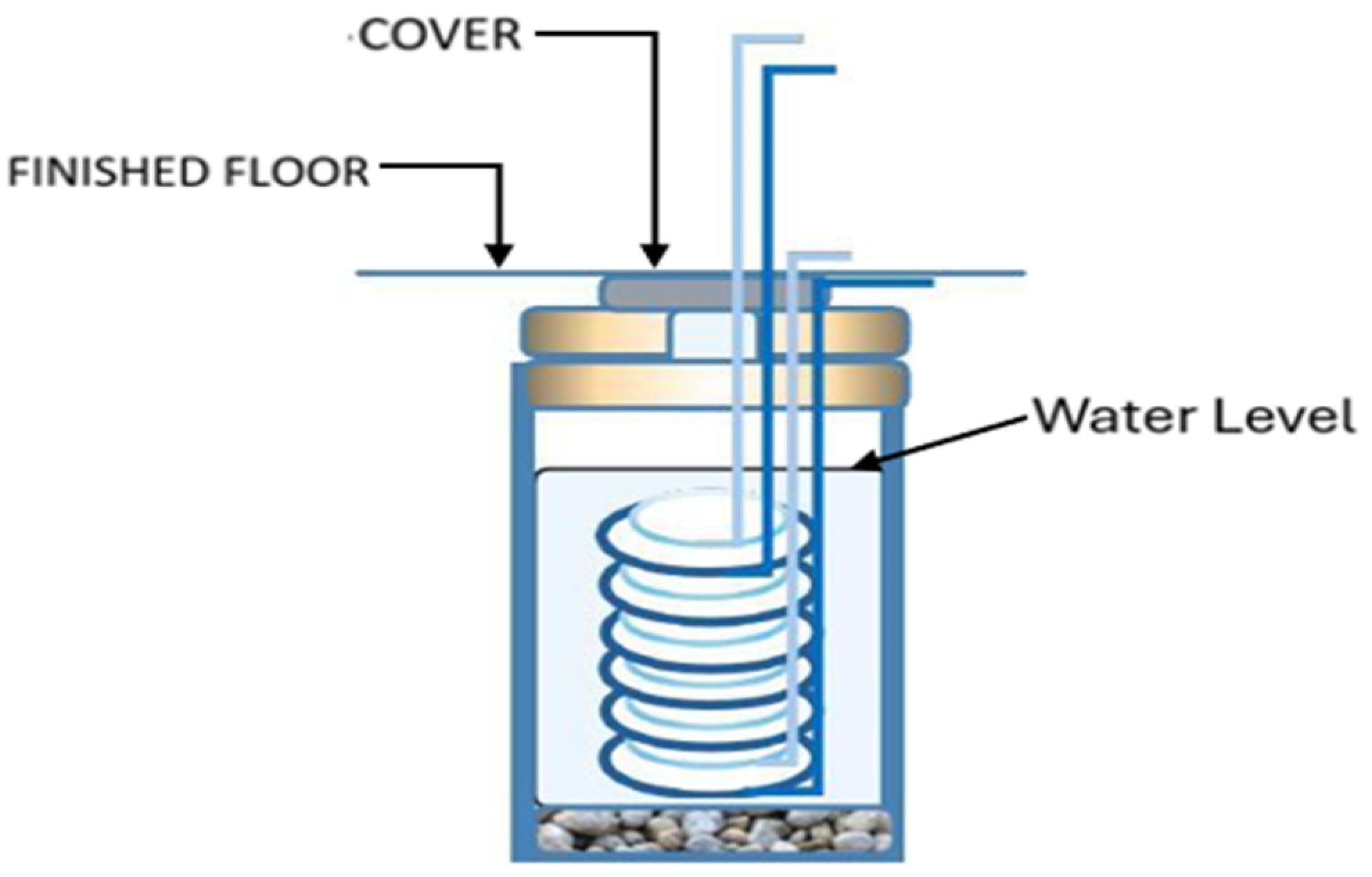
(b) One (1) double helical with a 6 m long coil in a well configuration with 0.5 m and 0.8 m spirals (shown in the sequel).
(c) One (1) open well complex consisting of two water-extraction wells and one-water injection well, each 16 m deep and 1 m in diameter (shown in the sequel).
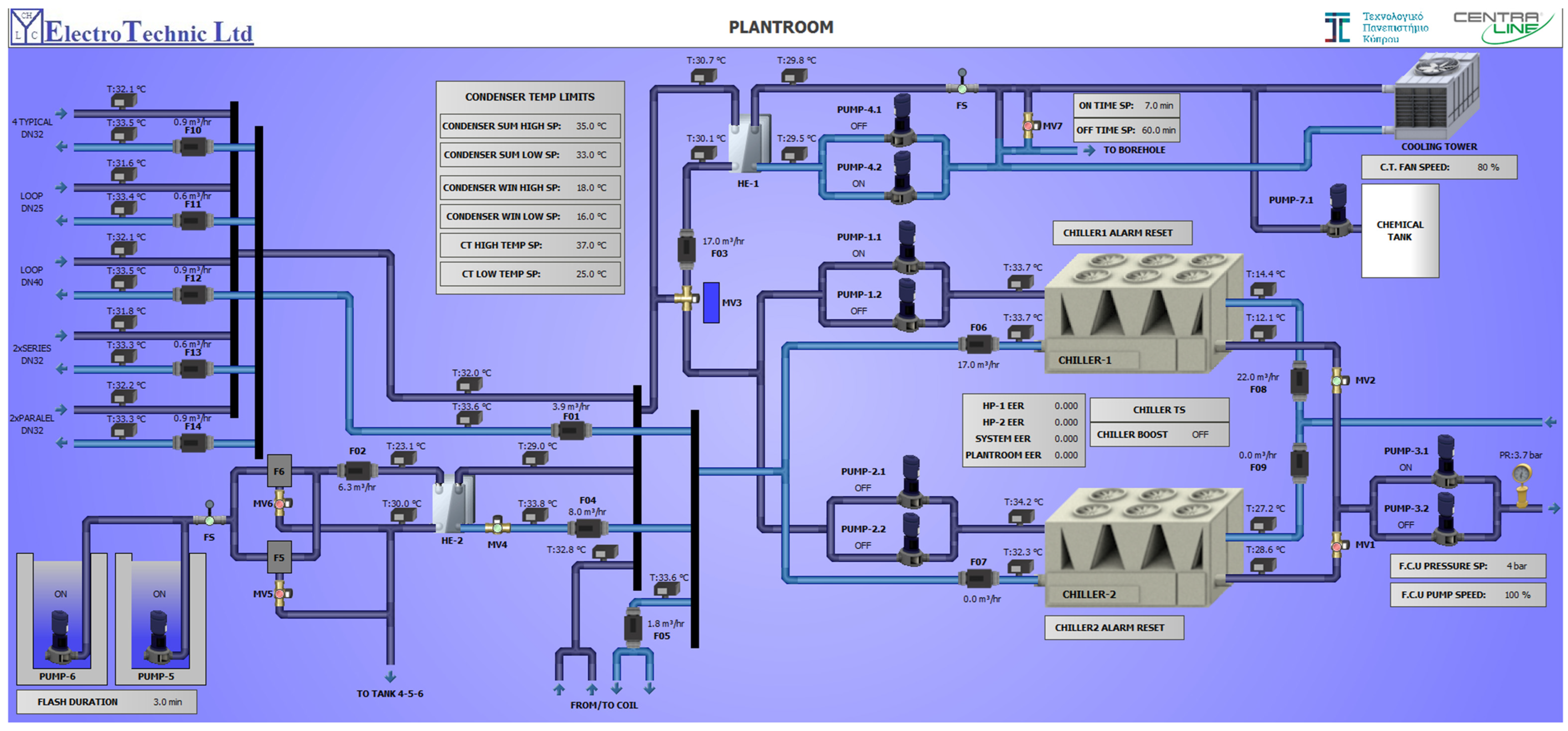
The GSHP system was separated into fourteen regions numbered from F01 to F14 (see Figure 2 for the system diagram with all features illustrated).
The general aim was to evaluate the performance of each of these groups separately through an analysis of data obtained by the BMS system, regarding energy, flow volume, incoming and outgoing temperatures in the system, which are automatically recorded in the BMS. The data, recorded every 15 min, can be used for the evaluation of the performance for each unit of the system, using appropriate mathematical formulas in the Microsoft Excel (Professional Plus 2019) tool. In particular, the heat flow rate (power) estimated Q ˙ (in kW), transferred to or from the system in each region F, is calculated from the equation:
Q ˙ = m ˙   c p ( T i n T o u t )
where m ˙ is the mass flow rate [kg s−1], c p is the specific heat of the circulating liquid [J kg−1 K−1] and T i n T o u t is the difference between the input and output temperatures of the circulating fluid [K]. For this study, recorded values were extracted for F01, which represents the boreholes (vertical GHEs); F04, which represents the open wells; and F05, which represents the helical GHE.

2.2. Cost and Energy Estimation

The installation cost of each GHE group can be calculated by adding the cost of the drilling, piping, labor, grouting and pumps. One can also estimate the operational and maintenance costs.
The library air conditioning system, installed in 2018, operated for the first time in 2019. Using data from 2019 (just before the COVID-19 pandemic), when the UMLL was in full operation, from the BMS offers the opportunity to calculate the contributed energy for each of the three GHEs groups. Finally, the total annual energy (for both summer and winter) contributed to the HP by each GHE group, as recorded by the BMS, was calculated.
The cost per kWh of each GHE group can be found by dividing the installation cost by the total contributed energy. The purpose of this is to examine which type of GHE is the most effective in relation to its installation and other costs.

3. Cost of the GHE Groups

This section presents a description and installation cost investigation of the GHE groups as described in Section 2. Table 1 and Figure 3 illustrate the different configurations/parameters of the eight vertical GHEs from the case study under investigation and the analytical cost of each vertical GHE configuration separately. The installation cost of a borehole was broken down into four main categories: drilling, piping, labor for installation and grouting cost.
In general, vertical GHEs are constructed using plastic polyethylene pipes, backfill material, and refrigerant fluid, allowing for minimal heat resistance between the pipes and the ground, while also ensuring good contact between the two materials. The drilling is usually 100 mm in diameter around each pipe [41]. An HE is installed vertically in the ground, which is typically 45–75 m deep for homes and more than 150 m for industrial enterprises [42]. To improve heat transfer, the choice of grout material must be carefully considered [33,43].
The spiral arrangement GHE is like traditional horizontal arrangements similarly positioned horizontally in shallow grooves, but their piping has a spiral pattern. At the end of each spiral, there is a straight pipe arrangement that transports the fluid to the HP [44]. These GHEs require less surface area than other horizontal configurations but require a longer length of piping [45]. Another variation of these systems is to position the spiral tubing vertically in narrow slots. These have the advantage of significantly reducing the necessary surface area, which contributes to the system’s cost. Because of their increased length and geometry, they require more pumping power to circulate the fluid, which reduces the installation’s efficiency [46]. A different configuration can also contain spiral GHEs immersed in water rather than in the ground. It is a spiral-shaped design that is slightly above the bottom and allows water to flow continuously around the piping [42]. The specific GHE of UMLL, as shown in Figure 4, consists of a double helical configuration in an open well of a 0.5 m and 0.8 m coil with 6 m height. The analytical cost of this double helical GHE is shown in Table 2.
Finally, regarding the geothermal well design, the engineer must consider the purpose and objective of the well, the conditions likely to be encountered downhole during drilling, the identification of material and equipment required, and safe drilling procedures that will ensure successful well completion and, thereafter, a satisfactory design life of the well. Casing-depth selection, material weight, and connection specifications are all part of the design process [47]. The well GHE complex of UMLL, as shown in Figure 5, consists of two open armored water extraction wells and one armored water injection well, each 16 m deep and 1 m in diameter. Table 3 shows the analytical cost of the open-well GHE complex.

4. Cost Estimation Per Useful Energy Contributed

The fact that there are data for 2019 from the BMS that records the energy flows in the various parts of the GSHP installation (Figure 2) offers the opportunity to calculate the cost of the contributed extracted energy per kWh in relation to the initial cost of installation of each of the three GHE groups, as described in Section 3.
Note that in general, open wells can be highly efficient and cost-effective where groundwater is plentiful and regulations permit—this is actually the case here. Helical coils offer a middle ground with potentially higher efficiency and moderate costs. Vertical boreholes provide reliable, low-maintenance performance suitable for a wide range of locations but at a higher initial cost [48].
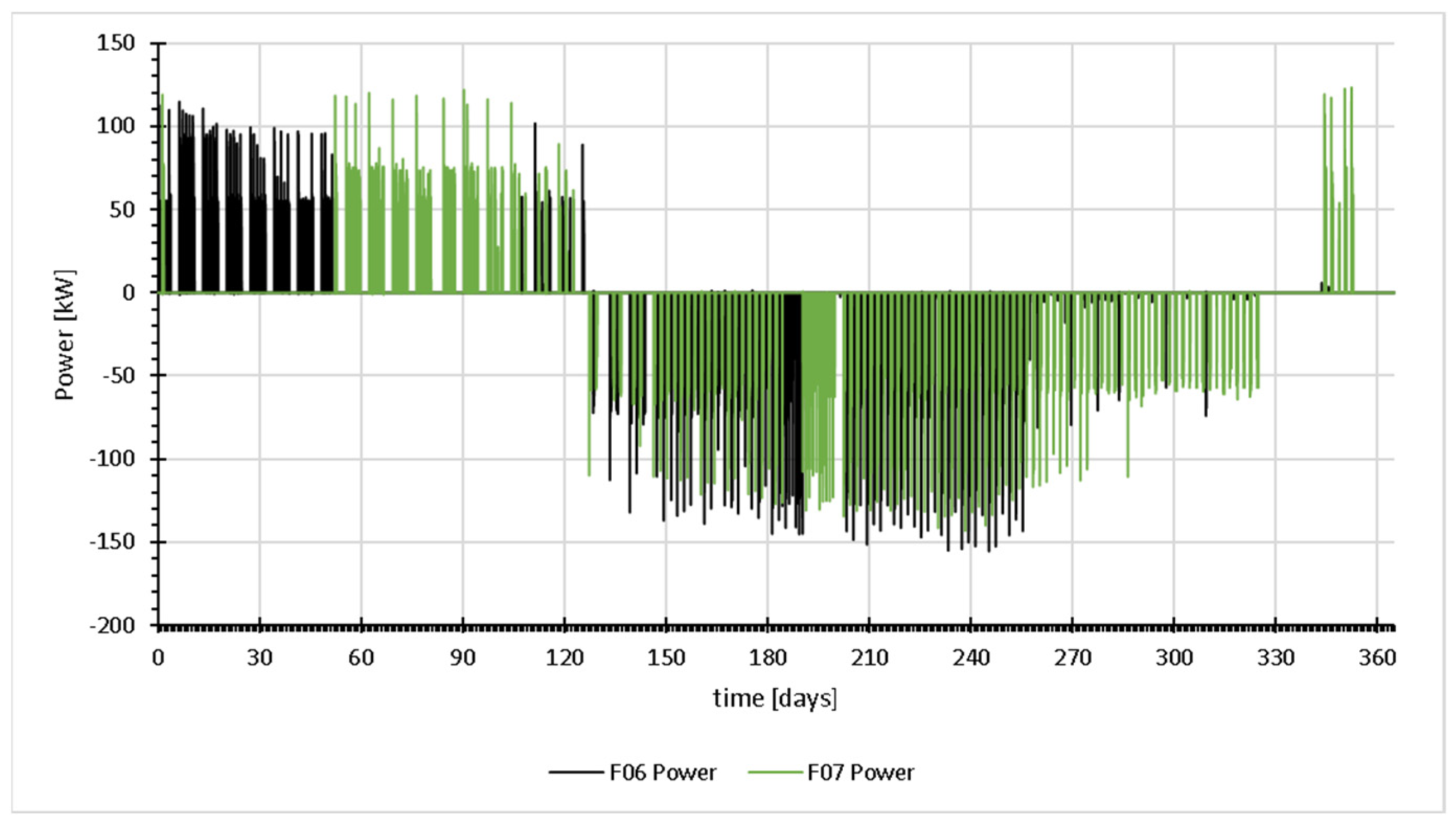
As seen in Figure 2, there are two chillers in the system that normally operate alternately every other day. In the event that any of the chillers is not functioning, it is replaced by the other chiller. Figure 6 shows the input power in the two chillers, recorded every 15 min throughout 2019. One can see that initially, Chiller 1 (F06—black) was in operation for about 2 months, followed by Chiller 2 (F07—green) for the next 2 months. After that period, the BMS was programmed so that the two chillers were operating on alternating days. The peak power values were at ~110 kW and ~150 kW for the winter and summer periods, respectively.
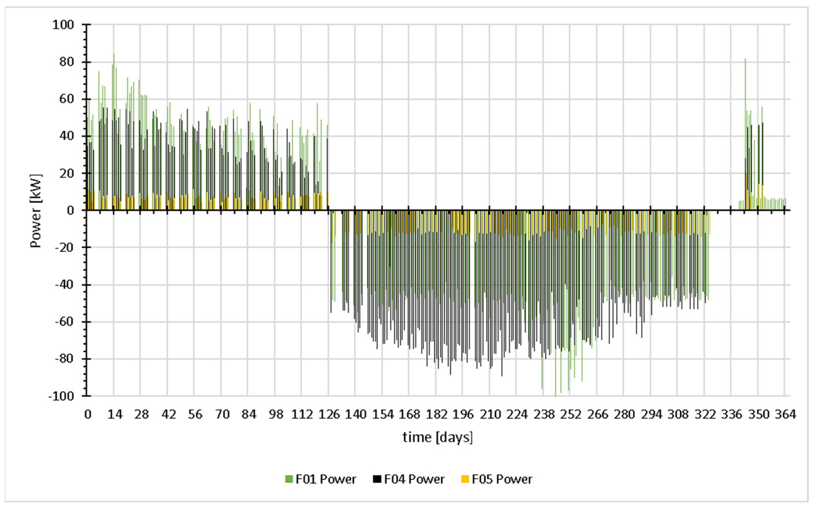
The input power to the chillers can be analyzed into the input of the three sources of contribution (Figure 7), that of the vertical GHEs (F01—green), the complex of the open wells (F04—black) and that of the helical coil (F05—yellow). As can be seen, the power for winter (summer) can vary for the boreholes for a maximum of about 85 kW (100 kW), for the system of the open well to a maximum of 55 kW (85 kW) and for helical coil to a maximum of 15 kW (15 kW).
For the reader’s sake, concerning summer, a magnified version of the part of the graph in Figure 7 is given in Figure 8, where a more detailed and clear view for the days of June and July 2019 is shown. It can be observed that the daily contribution of the three GHE groups is not always the same, with the open wells generally contributing the larger amount of power. There are, though, cases where the boreholes (vertical GHEs) offer greater power depending on the ground conditions and the open well water temperature.
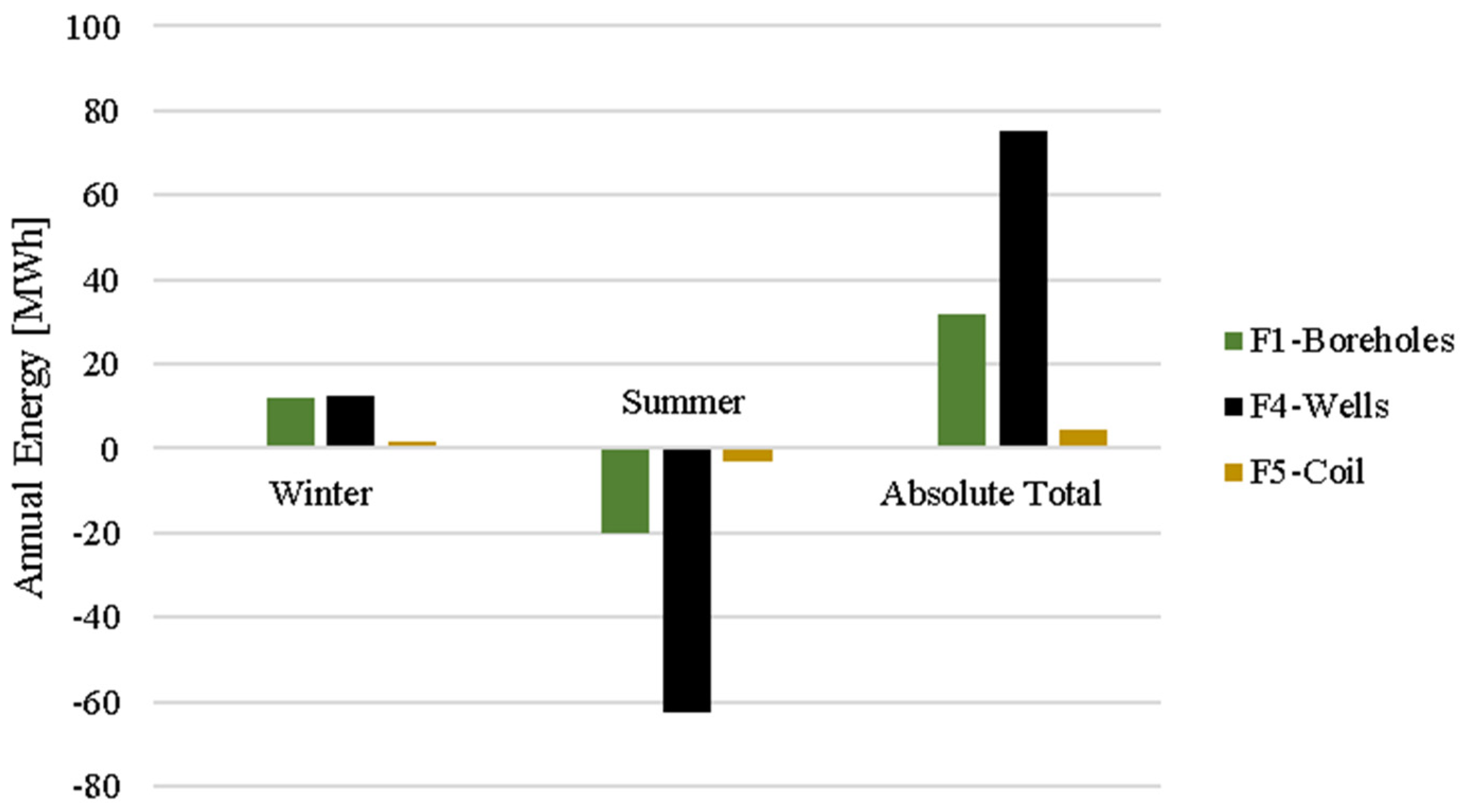
Finally, Figure 9 shows the annual (2019) energy in kWh, contributed by the three GHE groups (boreholes: F01—green color; wells: F04—black color; coil: F05—yellow color). It is clear that annually, the well complex offers the greatest amount of energy, with a total of 75,046 kWh (270,166 MJ). In summer, when the amount of energy required for the needs of the library’s cooling is far higher than in winter (typical of the Mediterranean weather of a coastal area in Cyprus), the superiority of the well complex is more evident.
Checking the summer-specific conditions in the recorded BMS data for 2019, it can be observed that although the total flow in the boreholes is approximately the same as the flow in the wells GHE, the average temperature difference is 1.4 °C in the boreholes, but 4.4 °C in the well, legitimizing the great difference in energy absorption in the wells during summer. Clearly, the wells perform more efficiently than the rest of GHEs. Note that these results apply to the specific area in Limassol that has adequate underground water at low depth.
However, to make a decision on which type of GHE is the most favorable in the specific case, one has to consider the ratio between the cost and the energy contribution. Initially, one such indication can come from the use of the system in the first year. The three groups of GHEs operate simultaneously when one of the two chillers of the GSHP system is in operation. The pumps for the well complex (2.7 kW) are about 5 times larger than the corresponding pumps of the vertical GHEs and the helical coil. In terms of energy, this means about 3500 kWh yearly consumption for the wells and about 700 kWh for the each of the rest. This will have a not-so-significant effect in the calculations. Hence, the operating cost could be considered about the same for all three and be neglected. For the first year of operation, there was no maintenance cost. As the maintenance cost (none, actually, after 5+ years of operation) is not predictable and not expected to be significant, one can also skip such costs for the purposes of this study. Therefore, one can also skip this cost for such a comparative study. Subsequently, the cost per kWh (for 1 year) for each GHE group will be the ratio of the installation cost and the (absolute) total energy contributed to the chillers. Table 4 shows the winter, summer and total energy contributed by each corresponding GHE group, the installation cost and the cost per kWh. The results indicate that the open wells have the lowest cost per unit energy extracted/rejected by the system (0.32), followed by the boreholes (1.05) and lastly by the coil (2.77).
The result above may be due to fact that, in general, open wells are less complicated and costly to build and operate than helical coils or U-tube boreholes, which call for more involved installation and drilling procedures. In addition, open wells use higher quantities of water than U-tubes and coils, with direct transfers to the system without any intermediate transfers though heat exchanger piping. In open wells, the water is not stagnant and dissipates heat to the ground much easier. Another advantage of open wells is that they are easy to access for maintenance and repairing a fact providing a quicker correcting response in the case of a faulty operation.
In addition to the above, it would be interesting to compare the above costs with an indicative number that could be obtained if the above GSHP system was replaced by a water-source HP with a cooling tower. In the same installation, an appropriate cooling tower exists as a backup to the geothermal system. The cost of the cooling tower, water tank and installation amount to EUR25,000. Assuming the same working conditions, the total heat rejected to the ground for the summer period is 85,649 kWh (308,336 MJ) (Table 4). Then, the corresponding summer cost per kWh for the cooling tower would be 0.29. This figure looks superior to all GHE groups, but it only covers the summer. If one considers an additional cost of about EUR10,000 for winter for a water–air HE and its controls, then the ratio would increase to 0.32. In addition, the cooling tower has similar electricity, compared to the HE pumps, but additional and considerable water running costs. One should also consider that the life cycle of a cooling tower is about 20 years, with considerable maintenance costs throughout its life. In the case of the geothermal system, the life cycle is about 50 years with basic maintenance cost. These considerations would increase even further the relevant ratio for the water-source heat pump with a cooling tower.

5. Conclusions

The purpose of this study was to compare the operation of various types of GHEs that were present in a GSHP system mounted on the coast of Cyprus’ Mediterranean environment. This study analyzed the installation costs and energy contribution of certain GHEs to a GSHP system with a cooling and heating capacity of around 100 kW.
It turns out that the operating and maintenance costs are not significant in the calculations and could be ignored for all three types of GHEs considered, namely a borehole (vertical) GHE group, a double helical coil and an open-well GHE complex. The installation cost was estimated at ~EUR33,550 for the borehole (vertical) GHE group, ~EUR12,800 for the double helical GHE, and ~EUR24,200 for the open-well GHE complex. The total energy input contribution was at ~31,860 kWh for the borehole (vertical) GHE group, ~4625 kWh for the double helical GHE and ~EUR75,050 for the open-well GHE complex.
The input contribution from the GHEs to the HP is 85,650 kWh (308,304 MJ) in summer and 25,880 kWh (93,168 MJ) in winter. Among the three groups of GHEs investigated, it is shown that the open-well GHE complex has the lowest cost per kWh (0.32 EUR/kWh), followed by the vertical GHE complex (1.05 EUR/kWh) and lastly by the helical coil GHE (2.77 EUR/kWh). This clearly suggests that when underground water is available, the open-well GHE is much more favorable than other GHE types. The importance of the figures above is that they can give direction to engineers toward making decisions about using the appropriate type of GHE in similar situations.
The superiority of open wells with regard to the cost per kWh could be explained as follows. Compared to the helical coils or U-tube boreholes, which require more involved installation and drilling operations, open wells are less expensive and complicated to create and operate. Furthermore, because open wells transmit water directly to the system without the need for intermediary transfers via the heat exchanger pipework, they circulate more water than U-tubes and coils. Since the water in open wells is not stagnant, heat is transferred to the earth considerably more easily. Open wells also have the benefit of being easily accessible for upkeep and repairs, which allows for a speedier reaction in the event of a malfunction.
When assessing the results, one has to say that the ratios above may vary according to errors in recordings. Considering that the errors (see Section 2) are the same for all temperature and flow meter sensors, one cannot claim a significant error in the difference between the readings for the different GHE groups. However, in order to obtain results of a higher statistical confidence, one has to repeat the “experiment” a few more times, i.e., take yearly recordings for a few more years, starting with 2023 when the UMLL was put in full operation after the COVID-19 pandemic years.

Author Contributions

Conceptualization, G.A.F. and P.C.; methodology, C.C., G.A.F. and P.C.; investigation, C.C., I.I.S., L.A., G.A.F. and P.C.; writing—original draft preparation, C.C., I.I.S., L.A., G.A.F. and P.C.; writing—review and editing, C.C., G.A.F. and P.C.; visualization, C.C. and L.A.; supervision, G.A.F. and P.C.; project administration, P.C.; funding acquisition, P.C. All authors have read and agreed to the published version of the manuscript.

Funding

The work presented in this paper has been undertaken in the framework of the research project WAGEs–SMALL SCALE INFRASTRUCTURES/1222/0234, which is co-funded by the Cyprus Research and Innovation Foundation and the European Regional Development Fund, under the Integrated Projects call of the “RESTART 2016-2020” Programme for Research, Technological Development and Innovation.

Data Availability Statement

Data sharing is available upon request.

Conflicts of Interest

The authors declare no conflicts of interest.

References

  1. Lu, S.M. A global review of enhanced geothermal system (EGS). Renew. Sustain. Energy Rev. 2018, 81, 2902–2921. [Google Scholar] [CrossRef]
  2. Hou, J.; Cao, M.; Liu, P. Development and utilization of geothermal energy in China: Current practices and future strategies. Renew. Energy 2018, 125, 401–412. [Google Scholar] [CrossRef]
  3. Pouloupatis, P. Determination of the Thermal Characteristics of the Ground in Cyprus and Their Effect on Ground Heat. Ph.D. Dissertation, Brunel University, London, UK, 2014. [Google Scholar]
  4. Kalogirou, S.A.; Florides, G.A.; Pouloupatis, P.D.; Christodoulides, P.; Joseph-Stylianou, J. Artificial neural networks for the generation of a conductivity map of the ground. Renew. Energy 2015, 77, 400–407. [Google Scholar] [CrossRef]
  5. Busby, J. UK shallow ground temperatures for ground coupled heat exchangers. Q. J. Eng. Geol. Hydrogeol. 2015, 48, 248–260. [Google Scholar] [CrossRef]
  6. Hodgson, J. An Examination of the Problem of Utilizing the Earth’s Internal Heat. 1901–1950; Harrison and Sons: Ventura, CA, USA, 1927; ISBN B002ZU9L4E. [Google Scholar]
  7. Robins, J.C.; Kesseli, D.; Witter, E.; Rhodes, G. 2022 GETEM Geothermal Drilling Cost Curve Update. Trans.Geotherm. Resour. Counc. 2022, 46, 2029–2040. [Google Scholar]
  8. Christodoulides, P.; Christou, C.; Florides, G.A. Ground Source Heat Pumps in Buildings Revisited and Prospects. Energies 2024, 17, 3329. [Google Scholar] [CrossRef]
  9. Robert, F.; Gosselin, L. New methodology to design ground coupled heat pump systems based on total cost minimization. Appl. Therm. Eng. 2014, 62, 481–491. [Google Scholar] [CrossRef]
  10. Vekony, A.T. Ground Source Heat Pump Prices n.d. Available online: https://www.greenmatch.co.uk/ground-source-heat-pump/prices (accessed on 23 August 2024).
  11. Aditya, G.R.; Mikhaylova, O.; Narsilio, G.A.; Johnston, I.W. Comparative costs of ground source heat pump systems against other forms of heating and cooling for different climatic conditions. Sustain. Energy Technol. Assess. 2020, 42, 100824. [Google Scholar] [CrossRef]
  12. Shamoushaki, M.; Fiaschi, D.; Manfrida, G.; Niknam, P.H.; Talluri, L. Feasibility study and economic analysis of geothermal well drilling. Int. J. Environ. Stud. 2021, 78, 1022–1036. [Google Scholar] [CrossRef]
  13. Dumas, P.; Antics, M.; Ungemach, P. Report on Geothermal Drilling; Europe Union GeoElec: Bruxelles, Belgium, 2013. [Google Scholar]
  14. Malhotra, M.; Li, Z.; Liu, X.; Lapsa, M.; Bouza, T.; Vineyard, E. Heat Pumps in the United States: Market Potentials, Challenges and Opportunities, Technology Advances; U.S. Department of Energy, Office of Scientific and Technical Information: Oak Ridge, TN, USA, 2023; pp. 1–12.
  15. European Heat Pump Association. Subsidies for Residential Heat Pumps in Europe; European Heat Pump Association: Bruxelles, Belgium, 2023. [Google Scholar]
  16. Huayhua, D.C.; Nieto Lapa, J.H.; Camargo Hinostroza, S.D. Geothermal Energy: Energy Alternative to Combat Frosts and Cold Spells in Perú BT—Renewable Energy Systems and Sources; Kolhe, M.L., Ed.; Springer Nature: Singapore, 2023; pp. 63–72. [Google Scholar]
  17. Lu, Q.; Narsilio, G.A.; Aditya, G.R.; Johnston, I.W. Economic analysis of vertical ground source heat pump systems in Melbourne. Energy 2017, 125, 107–117. [Google Scholar] [CrossRef]
  18. Yu, H.; Xu, T.; Yuan, Y.; Gherardi, F.; Tian, H. Single well geothermal heating systems: Technical and economic assessment of two widely-used configurations. J. Hydrol. 2024, 635, 131126. [Google Scholar] [CrossRef]
  19. Rybach, L. 7.06—Shallow Systems: Geothermal Heat Pumps; Elsevier Ltd.: Amsterdam, The Netherlands, 2012; Volume 7. [Google Scholar] [CrossRef]
  20. Du, D.; Li, Y.; Wang, K.; Zhao, Y.; Hu, Z.; Zhang, W.; Wang, Q. Experimental and numerical simulation research on heat transfer performance of coaxial casing heat exchanger in 3500 m-deep geothermal well in Weihe Basin. Geothermics 2023, 109, 102658. [Google Scholar] [CrossRef]
  21. Gharibi, S.; Mortezazadeh, E.; Hashemi Aghcheh Bodi, S.J.; Vatani, A. Feasibility study of geothermal heat extraction from abandoned oil wells using a U-tube heat exchanger. Energy 2018, 153, 554–567. [Google Scholar] [CrossRef]
  22. Harris, B.E.; Lightstone, M.F.; Reitsma, S.; Cotton, J.S. Analysis of the transient performance of coaxial and u-tube borehole heat exchangers. Geothermics 2022, 101, 102319. [Google Scholar] [CrossRef]
  23. Saeidi, R.; Noorollahi, Y.; Esfahanian, V. Numerical simulation of a novel spiral type ground heat exchanger for enhancing heat transfer performance of geothermal heat pump. Energy Convers. Manag. 2018, 168, 296–307. [Google Scholar] [CrossRef]
  24. Park, H.; Lee, S.R.; Yoon, S.; Shin, H.; Lee, D.S. Case study of heat transfer behavior of helical ground heat exchanger. Energy Build. 2012, 53, 137–144. [Google Scholar] [CrossRef]
  25. Yang, J. Geothermal Energy, Technology and Geology; National Geographic Headquarters: Washington, DC, USA, 2013. [Google Scholar]
  26. Rajeh, T.; Al-Kbodi, B.H.; Yang, L.; Zhao, J.; Zayed, M.E. A novel oval-shaped coaxial ground heat exchanger for augmenting the performance of ground-coupled heat pumps: Transient heat transfer performance and multi-parameter optimization. J. Build. Eng. 2023, 79, 107781. [Google Scholar] [CrossRef]
  27. Wang, G.; Song, X.; Yu, C.; Shi, Y.; Song, G.; Xu, F.; Ji, J.; Song, Z. Heat extraction study of a novel hydrothermal open-loop geothermal system in a multi-lateral horizontal well. Energy 2022, 242, 122527. [Google Scholar] [CrossRef]
  28. Bandos, T.V.; Campos-Celador, Á.; López-González, L.M.; Sala-Lizarraga, J.M. Finite cylinder-source model for energy pile heat exchangers: Effects of thermal storage and vertical temperature variations. Energy 2014, 78, 639–648. [Google Scholar] [CrossRef]
  29. Wood, C.J.; Liu, H.; Riffat, S.B. An investigation of the heat pump performance and ground temperature of a piled foundation heat exchanger system for a residential building. Energy 2010, 35, 4932–4940. [Google Scholar] [CrossRef]
  30. Iosif Stylianou, I.; Tassou, S.; Christodoulides, P.; Panayides, I.; Florides, G. Measurement and analysis of thermal properties of rocks for the compilation of geothermal maps of Cyprus. Renew. Energy 2016, 88, 418–429. [Google Scholar] [CrossRef]
  31. Koohi-Fayegh, S.; Rosen, M.A. Modeling of vertical ground heat exchangers. Int. J. Green Energy 2021, 18, 755–774. [Google Scholar] [CrossRef]
  32. Huang, Y.; Zhang, Y.; Hu, Z.; Lei, H.; Wang, C.; Ma, J. Economic analysis of heating for an enhanced geothermal system based on a simplified model in Yitong Basin, China. Energy Sci. Eng. 2019, 7, 2658–2674. [Google Scholar] [CrossRef]
  33. Stylianou, I.I.; Tassou, S.; Christodoulides, P.; Aresti, L.; Florides, G. Modeling of vertical ground heat exchangers in the presence of groundwater flow and underground temperature gradient. Energy Build. 2019, 192, 15–30. [Google Scholar] [CrossRef]
  34. Perego, R.; Pera, S.; Galgaro, A. Techno-economic mapping for the improvement of shallow geothermal management in southern Switzerland. Energies 2019, 12, 279. [Google Scholar] [CrossRef]
  35. Galgaro, A.; Di Sipio, E.; Teza, G.; Destro, E.; De Carli, M.; Chiesa, S.; Zarrella, A.; Emmi, G.; Manzella, A. Empirical modeling of maps of geo-exchange potential for shallow geothermal energy at regional scale. Geothermics 2015, 57, 173–184. [Google Scholar] [CrossRef]
  36. Viesi, D.; Galgaro, A.; Visintainer, P.; Crema, L. GIS-supported evaluation and mapping of the geo-exchange potential for vertical closed-loop systems in an Alpine valley, the case study of Adige Valley (Italy). Geothermics 2018, 71, 70–87. [Google Scholar] [CrossRef]
  37. Cocchi, S.; Castellucci, S.; Tucci, A. Modeling of an air conditioning system with geothermal heat pump for a residential building. Math. Probl. Eng. 2013, 2013, 781231. [Google Scholar] [CrossRef]
  38. Katsura, T.; Saito, K.; Oe, M.; Nagano, K. Installation Cost and Heat Extraction Performance Analysis of H-Shaped PC Pile Ground Heat Exchangers for Small Buildings. Energies 2024, 17, 891. [Google Scholar] [CrossRef]
  39. Luo, J.; Zhao, H.; Gui, S.; Xiang, W.; Rohn, J.; Blum, P. Thermo-economic analysis of four different types of ground heat exchangers in energy piles. Appl. Therm. Eng. 2016, 108, 11–19. [Google Scholar] [CrossRef]
  40. Risinggård, V.K.; Sivertsen, O.; Thisted, U.; MidttØmme, K. Performance study and life-cycle cost analysis of a ground-source heat-pump system in a commercial building in Norway. Sci. Technol. Built Environ. 2023, 29, 131–145. [Google Scholar] [CrossRef]
  41. Javadi, H.; Mousavi Ajarostaghi, S.S.; Rosen, M.A.; Pourfallah, M. Performance of ground heat exchangers: A comprehensive review of recent advances. Energy 2019, 178, 207–233. [Google Scholar] [CrossRef]
  42. Self, S.J.; Reddy, B.V.; Rosen, M.A. Geothermal heat pump systems: Status review and comparison with other heating options. Appl. Energy 2013, 101, 341–348. [Google Scholar] [CrossRef]
  43. Yang, W.; Shi, M.; Liu, G.; Chen, Z. A two-region simulation model of vertical U-tube ground heat exchanger and its experimental verification. Appl. Energy 2009, 86, 2005–2012. [Google Scholar] [CrossRef]
  44. Mustafa Omer, A. Ground-source heat pumps systems and applications. Renew. Sustain. Energy Rev. 2008, 12, 344–371. [Google Scholar] [CrossRef]
  45. Cui, P.; Li, X.; Man, Y.; Fang, Z. Heat transfer analysis of pile geothermal heat exchangers with spiral coils. Appl. Energy 2011, 88, 4113–4119. [Google Scholar] [CrossRef]
  46. Lee, C.K. Effects of multiple ground layers on thermal response test analysis and ground-source heat pump simulation. Appl. Energy 2011, 88, 4405–4410. [Google Scholar] [CrossRef]
  47. Hole, H. Geothermal Well Design—Casing And Wellhead. World Geotherm. Congr. 2010, 26, 1–28. [Google Scholar]
  48. Beier, R.A. Thermal response tests on deep borehole heat exchangers with geothermal gradient. Appl. Therm. Eng. 2020, 178, 115447. [Google Scholar] [CrossRef]
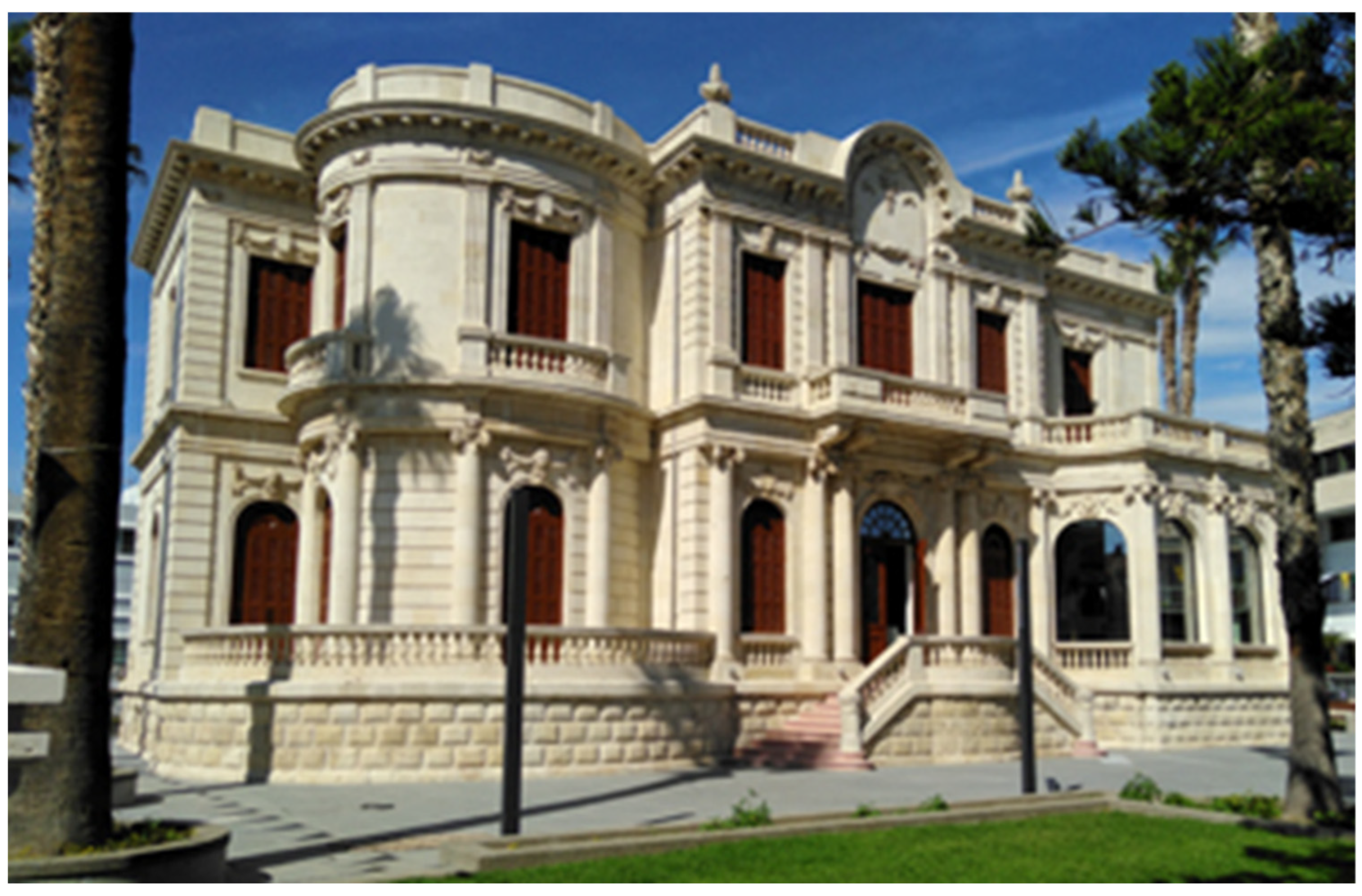
Figure 1. The historical building of the University Municipal Library of Limassol (UMLL).
Energies 17 04621 g001
Figure 2. Diagram of the GSHP system of the UMLL.
Energies 17 04621 g002
Figure 3. Schematic diagram of the eight vertical GHEs.
Energies 17 04621 g003
Figure 4. Double helical GHE configuration.
Energies 17 04621 g004
Figure 5. Open-well GHE complex.
Energies 17 04621 g005
Figure 6. Input power in the two chillers, recorded every 15 min throughout 2019. Chiller 1-F06, Chiller 2-F07 (see also Figure 2).
Energies 17 04621 g006
Figure 7. Input power to the chillers in 2019, analyzed into the contribution of the vertical GHEs (F01), the complex of the open wells (F04) and the helical coil (F05).
Energies 17 04621 g007
Figure 8. Input power to the chillers for June and July 2019, analyzed into the contribution of the vertical GHEs (F01), the open well complex (F04) and the helical coil (F05).
Energies 17 04621 g008
Figure 9. Annual (2019) energy contributed by the three GHE groups both in winter and summer (positive value means heat absorbed from the ground and negative heat rejected into the ground); the absolute total is the sum of absolute energies in winter and summer. The well complex offers by far the greatest amount of energy.
Energies 17 04621 g009
Table 1. Analytical cost of each configuration of vertical GHE in the system.
GHE TypeBoreholes
(No.)
Drilling (EUR)Piping
(EUR)
Labor
(EUR)
Grouting (EUR)Circulating Pump (EUR)Total
(EUR)
F10 * Typical Ø32 mm484141800450080030015,814
F11 Ø25 mm1135417515002003003529
F12 Ø40 mm1135475015002003004104
F13 Series 2 × Ø32 mm1155390020003003005053
F14 Parallel 2 × Ø32 mm1155390020003003005053
Total814,228452511,5001800150033,553
* See Figure 2.
Table 2. Analytical cost of double helical GHE.
GHEDrilling
(EUR)
Piping (EUR)Labor (EUR)Grouting
(EUR)
Circulating Pump (EUR)Total
(EUR)
Double helical in-well 0.5 m × 0.8 m coil—6 m height3000750851056030012,820
Table 3. Analytical cost of open-well GHE complex.
GHEDrilling
(EUR)
Piping (EUR)Labor
(EUR)
Gravel (EUR)Water Pump
(EUR)
Total
(EUR)
Well extracting water 16 m × Ø1 m100017570005603009035
3 × wells dropping water 16 m × Ø1 m300017510,000168030015,155
Total400035017,000224060024,190
Table 4. Winter, summer and total energy contributed by each corresponding configuration (kWh), the installation cost (EUR) and the cost per kWh, for comparison.
GHE GroupWinter
(kWh)
Summer
(kWh)
Absolute Total (kWh)Installation Cost (EUR)Cost (EUR) Per kWh
(1 Year)
F01-Boreholes11,792−20,065 *31,85733,5531.05
F04-Wells12,534−62,51275,04624,1900.32
F05-Helical Coil1551−3072462312,8202.77
Total25,877−85,649111,52670,5631.58 **
* The negative sign represents the heat rejected to the ground, ** Corresponds to the cost per kWh of the total energy contributed (F01 + F04 + F05).
Disclaimer/Publisher’s Note: The statements, opinions and data contained in all publications are solely those of the individual author(s) and contributor(s) and not of MDPI and/or the editor(s). MDPI and/or the editor(s) disclaim responsibility for any injury to people or property resulting from any ideas, methods, instructions or products referred to in the content.