Abstract
About one-third of world energy production is destined to the industrial sector, with process heat accounting for about 70% of this demand; almost half of this quota is required by endothermic processes operating at temperatures above 400 °C. Concentrated solar thermal technology, thanks to cost-effective high-temperature thermal energy storage solutions, can respond to the renewable thermal energy needs of the industrial sector, thus supporting the decarbonization of hard-to-abate processes. Particularly, parabolic trough technology using binary molten salts as heat transfer fluid and storage medium, operating up to 550 °C, could potentially supply a large part of the high-temperature process heat required by the industry. In this work, four industrial processes, representative of the Italian industrial context, that are well suited for integration with molten salt concentrators are presented and discussed, conceiving for each considered process a specific coupling solution with the solar plant, sizing the solar field and the thermal storage unit, and computing the cost of the process heat and its variation with the storage capacity. Considering cost data from the literature associated with the pre-COVID-19 era, an LCOH comprising the range 5–10 c€/kWhth was obtained for all the cases studied, while taking into account more updated cost data, the calculated LCOH varies from 7 to 13 c€/kWhth.
1. Introduction
Energy consumed by the industrial sector has a crucial impact on the global energy balance: an estimation of the global industry energy use [1] shows that industry is responsible for 32% of the overall energy consumption, with process heat accounting for about 70% of this demand. Furthermore, 30% of the process heat is required at temperatures below 150 °C, 22% at temperatures between 150 and 400 °C, and 48% at temperatures above 400 °C.
Regarding the specific European context, a quarter of total energy consumption is attributable to the industrial sector, which requires 60% of electricity and 40% of heat [2]. From analyses conducted by the Joint Research Center of the European Commission [3], European industrial heat demand is mostly attributable to high-temperature processes (Figure 1).
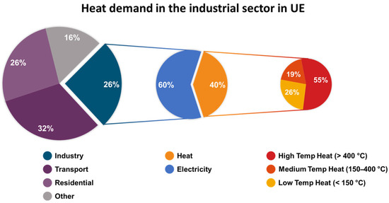
Figure 1.
Final energy consumption and breakdown of useful heat demand by European countries [2].
A comprehensive study of the thermal energy consumption of European industry [2] shows that the largest proportion of high-temperature heat demand is accounted for by metallurgical industries (iron, steel, and aluminum), non-metallic mining industries (especially the cement industry), and some processes in the chemical industry. Low- and medium-temperature heat demand, on the other hand, refers to the food, beverage, tobacco, paper, painting, and textile industries. Representative endothermic processes, characterized by essentially homogeneous operating conditions, such as thermal levels and heat transfer/process fluids, can be associated with each industrial sector, as shown in Table 1.

Table 1.
Main endothermic processes in industry: operating temperature ranges and process HTFs [4,5,6,7].
Currently, thermal energy for industrial processes is produced through the combustion of fossil fuel in boilers and furnaces: approximately 40% of industrial primary energy consumption is covered by natural gas and approximately 41% by petroleum [8], causing the release of significant amounts of carbon dioxide, accounting for about one-third of global emissions [4]. Adding to the environmental challenge is the problem of fossil resource provision, which is becoming increasingly urgent due to geopolitical instabilities and the need to ensure the security of the energy supply.
Globally, the International Energy Agency (IEA) forecasts a 50% rise in industrial energy demand by 2050 if current policies remain unchanged. This highlights the pressing need for a widespread transition to clean technologies within the industrial sector [9].
Solar, wind, hydro, and geothermal energy represent sustainable alternatives to reduce or even eliminate dependence on conventional fossil resources.
Several studies have assessed the technical potential of Solar Industrial Process Heat (SHIP) for various countries and on a global scale [10]. The International Renewable Energy Association (IRENA) estimates that SHIP could reach a best-case potential of 15 EJ by 2030, representing a significant portion of the projected total industrial energy use of 173 EJ in the same year [8].
Lower temperature processes (below 80 °C) can be readily addressed with commercially available systems like flat plate collectors (FPCs) and evacuated tube collectors (ETCs). For medium-temperature applications, advanced collector designs have been successfully developed [8]. Additionally, ultra-high vacuum FPCs or ETCs equipped with concentrators can achieve temperatures up to 200 °C. For higher-temperature heat demands, solar thermal concentrators (STC) like parabolic trough collectors and linear Fresnel collectors can generate superheated steam and/or directly supply thermal heat to the endothermic processes. STC technology is particularly well suited to provide renewable heat to the industry for the following reasons:
- It directly supplies renewable heat without electric-to-heat conversion and its related energy waste;
- Thermal energy is relatively easy to store, with efficient and economically viable solutions for realizing energy storage of 15 h and more [11];
- An industry, or an industrial ecosystem, which deals with medium-to-high-temperature applications, is intrinsically suited to cope with a solar plant, particularly if the thermal energy vector of the industrial process and solar plant coincides.
However, up to now, the heat supply from a solar source is mainly limited to low-grade heat supply for food, beverage, transport equipment, textile, machinery, pulp, and paper industries, where roughly 60% of the heating needs can be met by temperatures below 250 °C [8]. The widespread adoption of solar process heat faces a significant challenge due to the structure of the industrial sector itself. The presence of small- and medium-sized enterprises (SMEs) presents two key hurdles: integrating solar heat into their existing, often optimized thermal energy systems, and a general lack of familiarity with the technology itself. To overcome these bottlenecks, solar process heat solutions must be adaptable and tailored to the specific energy demands of individual industrial locations.
In this regard, Table 2 provides matching of the main STC technology options (including type of solar collectors, heat transfer fluid (HTF), and storage medium (HSM)) and their possible applications for supplying heat/steam to industry for different thermal levels and sizes of industrial users.

Table 2.
Matching main CST technology options and heat/steam supply in industry [7].
Concerning HTFs, in the case of low-temperature applications, it may be convenient to use paraffinic oils (less toxic than aromatic oils), while at medium temperature for small utilities, it is appropriate to use aromatic oils, which are stable up to 400 °C and are usually used in the industrial heat transport sector, and at medium/high temperature, especially in the case of large plants, molten salt mixtures (binary or ternary) are very promising due to their high thermal stability and environmental sustainability.
Regarding the thermal storage systems, in principle, it is always preferable to adopt the direct thermal storage option, in which the heat transfer fluid coincides with the storage medium. For large utilities and large storage capacities, the most reliable storage option is the commercially established two-tank system [12]. However, in view of thermal storage cost reduction, thermocline systems are under development [13,14], potentially suitable for doubling the density of stored energy through the use of a single tank in place of the two used in current commercial systems.
The adoption of linear collectors using molten salts as a heat transfer fluid—especially the so-called solar salts, a NaNO3/KNO3 mixture 60/40%wt—could potentially guarantee the supply of a large part of the energy required by the high-temperature endothermic processes since their working temperature can be as high as 550 °C; initially considered for thermal storage only [15] or for use in tower systems [16], solar salts have also been proposed as a viable heat transfer fluid for linear concentrators, both parabolic troughs [17] and linear Fresnel concentrators [18], with the realization of prototypes and pilot plants [19,20]. High-temperature thermal storage can be realized as a two-tank system [12] or as a thermocline storage [13]. Beyond solar salts, other molten salt mixtures can be theoretically applied for providing heat to the industrial sector depending on the temperature requirements of the industrial processes; in this regard, Figure 2 shows the operating temperatures of some relevant industrial endothermic processes along with the operating temperature intervals of different molten salt mixtures.
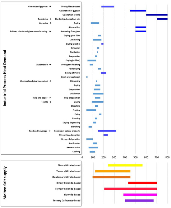
Figure 2.
Temperature ranges of Industrial Process Heat Demand and molten salt mixtures [4,5,6,7,21,22].
The aim of this work is to analyze, in realistic cases, the possible use of molten salt concentrators for supplying process heat to the industry. State-of-the-art STC technology (linear trough concentrators with a two-tank thermal) has been assumed, and four specific case studies, strictly connected to the Italian context, have been considered in order to assess the feasibility of the integration of existing production plants with existing STC technology that has already been tested for electricity production. The analysis considers different typologies of industrial processes and localizations, highlighting the technical specifications of the selected endothermic processes (operational thermal levels, heat load profiles, the possibility of heat recovery, etc.), the possible proposed solutions for supplying solar heat to the processes, the estimated performance of the solar plant, and the corresponding costs in terms of the Levelized Cost of Heat (LCOH). The results should provide useful indications on the feasibility and on the economic viability of supplying renewable solar heat to industrial processes via the analysis of specific and realistic cases.
2. Materials and Methods
2.1. Preliminary Screening
A screening of various industrial processes requiring heat at temperatures up to 550 °C—which is the output temperature of a linear molten salt collector—was initially performed. The parameters considered in the screening were the processes’ heat requirements, their operating temperatures, and the possibility of integrating the STC trough’s realistic and feasible heat exchangers.
2.2. Design of Heat Exchanger
For each selected process, a suitable heat exchanger design was chosen to transfer solar heat from molten salts to the industrial process itself. Different alternatives were considered for the heat exchanger typology (shell/tube, spiral tube, steam generators) and for the process fluid (air, steam, salts). Designing and sizing of heat exchangers were performed according to the well-known procedures applied in thermal engineering [23,24]. Convective heat transfer coefficients were obtained via Reynolds, Prandtl, and Nusselt numbers; soiling of the tubes was also considered to calculate the heat exchanger performance. Once we assumed the industrial process capacity—and, consequently, the given required input power—the sizing of the heat exchanger was performed through an iterative calculation based on the heat transfer fluid flow, specific and global thermal exchange coefficients, length, distance, and number of passages in the tubes and in the shell according to TEMA (Tubular Exchanger Manufacturers’ Association) design standards [25].
2.3. STC Modeling and Sizing
For the performance evaluation of the solar field, the SAM software (System Advisor Model, version 2023.12.17) developed by the National Renewable Energy Laboratory (NREL—USA) [26] was adopted. SAM software is a widely used and validated tool employed for modeling and simulating renewable energy production systems, generating both electric and/or thermal energy. The results of the present work were obtained via the simulation procedures implemented in the software.
Parabolic troughs were selected as concentrating systems, with a molten salt inlet temperature of 290 °C and an outlet temperature of 550 °C. The considered collector was a “Siemens Sunfield 6”, and the receiver tube was a “Schott PTR70” (8 collectors for each loop), as modeled in SAM software library. The thermal storage was a two-tank storage system. Its capacity is given in working hours at the nominal power.
The system was simulated assuming that the irradiation followed a Typical Meteorological Year (TMY), obtained from PVGIS [27,28]. The locations of the plants were chosen close to real production plants located in different regions of Italy to obtain realistic simulations: different from electricity generation, process heat production must be located close to the thermal energy user, and this limits the location choices.
The STC supplies energy to a two-tank system, which is directly connected to the process heat exchanger. Obviously, the tank storage level depends on the energy harvested during daytime and the energy required by the endothermic process.
The SAM model provides a yearly simulation of the plant, allowing us to obtain the fraction (hereinafter referred to as the heat supply factor) of the heat supplied by the STC and the total heat consumed by the process in order to evaluate the cost of the thermal energy generated. To clarify the procedure, in Figure 3, an example of the obtained time sequences from SAM simulations is shown relative to three consecutive summer days for a thermal user capacity of 10 MWth.
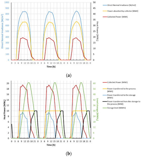
Figure 3.
Time sequences in three consecutive summer days (2–4 July) for the Trapani site of (a) Direct Normal Irradiance, power absorbed by the collector and the collected power; (b) power collected, transferred to the process, transferred to the storage, and transferred from the storage to the process. The storage level is also shown. The associated industrial process requires 10 MWth, and the storage size is 6 h.
The Levelized Cost of Heat (LCOH) was computed considering the Capital Expenditure (CAPEX) and the Operating Expenses (OPEX); in the case of a solar plant, CAPEX contribution was dominant. The calculation of CAPEX requires the estimation of plant components costs, including the cost of their design, realization, supervision of construction, and installation; these costs were drawn from specific publications [23,29,30]. OPEX costs can be divided in a fixed part and in a variable part depending on the production. Fixed OPEX costs include personal, maintenance, and assurance costs; variable OPEX costs include aging of components (and, consequently, their frequency of replacement) and electric and thermal additional consumption when the plant is in operation. OPEX costs were estimated relying on the SAM database. Once CAPEX and OPEX were estimated, the LCOH was evaluated actualizing the cost of the produced energy via the real discount factor (adjusted for inflation); for the purpose of the present work, a real discount factor of 3%/year was hypothesized.
In this study, a parametric analysis of LCOH and varying the solar field size and the storage capacity was performed. For each application, a set of selected values of realistic storage capacities was studied (0, 2, 6, 12, and 15 h), and for each capacity, the optimal size of the solar field (i.e., the size that minimizes the LCOH) was computed under the condition of having an integer number of collector loops. Therefore, five possible configurations were obtained and discussed for each application.
Cost parameters used for the estimation of the LCOH are shown in Table 3.

Table 3.
Cost parameters for the estimation of the CAPEX, OPEX, and LCOH.
It is worth noticing that the cost estimation of the solar field was conducted considering three different scenarios: Scenario A was aligned with data in the literature [30], while Scenario B was obtained from Scenario A considering benefits from learning rate and scale effects; however, corresponding cost results were both based on pre-COVID-19 experiences and evaluations before the subsequent inflation and economic turbulences. To obtain a more realistic cost assessment, an additional scenario (Scenario C) was here considered, updating the cost results of Scenario A to the present on the basis of chemical plant cost indices (CEPCI) [31]. Therefore, for each considered process, three LCOH values were computed corresponding to the three analyzed scenarios; this allowed us to consider a variety of possible evolutions of the market, from a favorable one (Scenario B, with a return to pre-COVID-19 stability and cost reduction by scale economy) to an unfavorable scenario (Scenario C).
The CAPEX for the storage and the heat exchangers was assessed on a case-by-case approach.
3. Results
3.1. Selected Processes
Four industrial processes were selected, representative of the Italian industrial sector:
- Drywall production. The production of drywall from chalk mineral proceeds in two phases. Step 1: starting from chalk mineral (CaSO4 · H2O), the material must be grinded and cooked to obtain an almost complete conversion to the -CaSO phase (90%) and to lose 75% of the inlet water. This procedure is performed in a mill (Figure 4), where the chalk is heated by an air flux entering at 450 °C and exiting at 170 °C. Step 2: the material is then mixed with water and additives and deposed between cardboard sheets; then, it must be dried with a flux of air at 280 °C. Table 4 shows the hypotheses here formulated on the production process along with the thermal power required by the two phases, assuming a plant production of 150,000 tons/year of drywall.
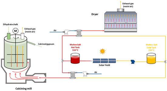 Figure 4. A conceptual scheme of a plant for the spray drying of chalk and drywall production.
 Table 4. Operating characteristics and production capacity of a typical plant for drywall production.
 - Spray drying of ceramics. In the production of ceramic tiles, the wet material (slip) is usually prepared in a spray dryer that causes the immediate evaporation of the water obtaining the ceramic powder. The drying is performed by a strong air flux entering the dryer at 500 °C. The plant scheme—already integrated with an STC—is represented in Figure 5. Table 5 shows the hypotheses here formulated on the production process along with the thermal power required for a plant with a production of 140,000 tons/year of ceramic powder.
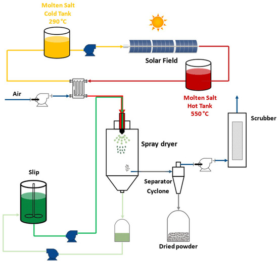 Figure 5. A conceptual scheme of a plant for the spray drying of ceramics. Beside the spray dryer, the scheme also shows additional elements (a cyclone separator and a scrubber, which cleans the exiting air flux from residual powder).
 Table 5. The operating characteristics and production capacity of a typical plant for the spray drying of ceramics.
 - Visbreaking. Visbreaking is, in general terms, a cracking process of heavy oils to increase the fraction of more valuable products, such as diesel. A possible process scheme is illustrated in Figure 6. Heavy oils are heated and then transferred to a soaker where the chemical reactions take place; the reaction products are subsequently transferred to a distillation column, where valuable sub-products are recovered. Working temperatures are in the range of 420–500 °C. It is worth noticing that the feeding of a visbreaker can be extremely variable since heavy oils can have a wide range of viscosities, compositions, and sulfur content. The main parameters of the process here considered are summarized in Table 6 (the assumed annual production capacity is 850,000 tons/year of processed oil).
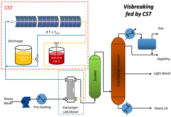 Figure 6. A conceptual scheme of a plant for the visbreaking of heavy oils.
 Table 6. The operating characteristics and production capacity of a typical plant for visbreaking.
 - Deodorization of oils for food industry. Oils used in the food industry can have unpleasant odors due to traces of volatile substances, such as aldehydes, ketones, terpenes, and others. Deodorization can be accomplished with the use of superheated steam that passes through a previously de-aerated oil in an evacuated column. A conceptual scheme of the plant is shown in Figure 7. The plant is fed by two steam fluxes, one at 450 °C for the oil heating and one at 160 °C that is used in the evacuated column. The main parameters of the process here considered are summarized in Table 7, assuming a production capacity of 300,000 tons/year.
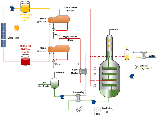 Figure 7. A conceptual scheme of a plant for the deodorization of oils.
 Table 7. The operating characteristics and production capacity of a typical plant for the deodorization of oils.
3.2. Heat Exchangers
For each considered process, a suitable heat exchanger design along with the associated heat transfer fluid was selected. The selected solutions are reported below.
- Drywall production. The process requires air fluxes at high temperature. For this reason, the most suitable choice for matching the process with the solar plant is a salt/air heat exchanger. A tube/shell heat exchanger design has poor performance for this specific application since the air flux per surface unit is limited and the turbulence is low, resulting in limited heat transfer coefficient. Thus, finned tube heat exchangers, invested by a transversal air flux, were here selected as suitable option.
- Spray drying of ceramics. As in the previous case, hot air is the process fluid; therefore, a salt/air finned tube heat exchanger was selected for this specific application.
- Visbreaking. In this case, the process fluid is heavy oil. Thus, a direct salt/oil heat exchanger was here chosen, eliminating the need for an intermediate heat transfer fluid. Two heat exchanger designs were initially evaluated: a tube-and-shell and a spiral type. In the spiral design, one fluid flows within a helical chamber, while the other flows in the remaining space. The second design is more complex but can be advantageous due to the high viscosity of the heavy oil. Preliminary studies showed, in fact, an advantage of this second option in terms of costs. Therefore, a spiral heat exchanger was chosen.
- Deodorization of oils for food industry. In this case, water steam is required by the process; thus, a steam generator fed by molten salts was selected as the reference option for the heat exchanger. Particularly, two steam generators can be used: one producing low-pressure steam to be directly injected into the oil and the other one generating high-pressure steam for the pre-heating step.
Table 8 shows the characteristics of the heat exchangers proposed.

Table 8.
Heat exchanger characteristics (thermal power supplied by molten salts was calculated considering heat exchanger efficiencies).
3.3. Integration with STC
As mentioned in the previous paragraphs, the design and the sizing of the solar plant to be coupled with each of the four described processes was performed by repeated simulations to obtain a parametric analysis of different configurations.
- Drywall production. The selected location for drywall production is the city of Trapani (Italy), where an important plant for chalk production is operative. The analysis results are shown in Table 9, where the values of the LCOH are given at the estimated cost for the solar field in the three scenarios (200, 150, and 260 €/m2, respectively). It is worth noting that the cost increases with the heat supply factor , but the increase is quite moderate (a 15–20% increase in the LCOH corresponds to a more than triplicated ).
 Table 9. LCOH for drywall production (location: Trapani, Sicily).
 - Spray drying of ceramics. In this specific case, the city of Modena was selected as the reference location since more than 80% of ceramic tiles production in Italy is concentrated in this region. The analysis results are shown in Table 10. Unfortunately, the irradiation of this area is quite limited, and this negatively impacts the cost of the produced energy, which is about 50% higher than in the previous example (the available DNI at Trapani is about 30% higher than the available DNI at Modena).
 Table 10. LCOH for spray drying of ceramics (location: Modena, Emilia-Romagna).
 - Visbreaking. The town of Gela in Sicily was selected as the reference location since Gela is a relevant site for oil refining industry. The analysis results are shown in Table 11. Among the proposed case studies, Gela is the location with the highest irradiation, and this favorably impacts the cost of the thermal energy produced by the solar plants.
 Table 11. LCOH for visbreaking (location: Gela, Sicily).
 - Deodorization of oils for food industry. Here, the selected location is the city of Brindisi, an important center for olive oil production. The analysis results are shown in Table 12. Despite the good solar irradiation in the south of Apulia, the calculated LCOH is higher than the ones obtained for Gela or Trapani due to the smaller size of the plant.
 Table 12. LCOH for deodorization of oils (location: Brindisi, Apulia).
4. Discussion
The calculated LCOH for the considered industrial processes substantially comprises the range 5–7 c€/kWhth in the pre-COVID-19 era, with the cost strictly depending on the site-available irradiation: the highest cost is associated with the spray drying of ceramics, where an LCOH around 7–10 c€/kWhth was obtained since the irradiation available at the site of Modena is significantly lower than the irradiation of the other three sites. Similarly, even considering the less favorable scenario (Scenario C), the LCOH varies from 7 to 10 c€/kWhth for all sites, except for the process located in Modena (11–13 c€/kWhth). The LCOH almost invariably increases with the storage capacity—and, consequently, with the heat supply factor —if the optimal size of the solar field is selected for each storage capacity considered. However, the for a plant without thermal storage is quite low, ranging from 0.082 to 0.152; only by accepting an extra cost for the energy produced on demand, a significant contribution from the solar source can be obtained. However, this extra cost is quite limited; considering the two extreme cases with no storage and with the longer storage duration (15 h), an extra cost between 7% and 17% is associated with an increase in heat supply cost of a factor of 2.5–3.5.
The components that contribute to the LCOH are shown in Figure 8. The CAPEX costs are dominant with respect to the OPEX, and the largest share of the cost is attributable to the solar field (around 25%); this means that progress in solar field manufacturing and components’ quality/lifetime can have a strong impact on the final LCOH. The contribution of the thermal storage to the LCOH is quite limited (less than 5%, including molten salts).
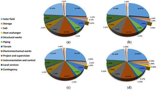
Figure 8.
The contribution of the different cost items to the LCOH (thermal storage of 6 h): (a) drywall production; (b) the spray drying of ceramics; (c) visbreaking; and (d) the deodorization of oil.
It is worth noting that the costs considered as benchmark in this paper (Scenario A) are well aligned with the literature data referring to the pre-COVID-19 period. On the basis of chemical plant cost indices [31] (Scenario C), an average increase in the LCOH of about 27% with respect to the Scenario A was obtained.
5. Conclusions
In this paper, the possible use of solar linear concentrators using molten salts as an HTF for supplying thermal energy to specific industrial processes at medium/high-temperature levels (up to 550 °C) was analyzed. Four industrial processes, representative of the Italian industrial context, were considered as case studies (drywall production, ceramic spray drying, visbreaking, and oil deodorization). For each selected process, a tailored solution for coupling the industrial process itself and the solar plant was conceived, sizing the solar field and the thermal storage unit and arriving at the assessment of the LCOH.
The analysis shows that in the case of a 15 h storage capacity, the generated solar heat covers up to 40% of the process energy demand, depending on the specific localization of the industrial site, which obviously must be installed close to the solar plant. The cost of the heat was evaluated in three different scenarios, from a favorable one (with a return to pre-COVID-19 stability and cost reduction by scale economy) to an unfavorable scenario (with updated costs affected by the recent inflation wave). Considering cost data from the literature, associated with the pre-COVID-19 era, an LCOH comprising the range 5–10 c€/kWhth was obtained for all the cases studied, while taking into account more updated costs, the calculated LCOH varies from 7 to 13 c€/kWhth. The highest cost was the ceramic spray drying located in Modena, where the available irradiation is significantly lower than the irradiation on the other three sites (Gela, Brindisi, and Trapani).
It should be noted that Modena can be considered as a limit case. Indeed, the application of STC technology, as far as electric energy production is concerned, is economically viable only in the presence of a high DNI and is usually recommended for southern locations. However, since process heat must be supplied at the production site, it is interesting to explore the possibility of supplying the process heat in non-optimal locations (e.g., in the northern part of Italy, which is the most industrialized part of the country). Clearly, for even more northern locations (such as northern Europe), the use of STC cannot be a viable solution.
Furthermore, from the present analysis, the LCOH referring to systems with a thermal storage of 15 h is 7–17% higher than systems without storage, depending on the specific applications. This moderate increase in the LCOH corresponds to a more relevant increase in the heat supply factor (by a factor of 2.5–3.5). The cost item with the highest impact on the LCOH appears to be the solar field (25–35%), while the cost of thermal storage (supply only) is lower than 5%. This means that progress in solar field manufacturing and components’ quality/lifetime can have a strong impact on the final LCOH.
Author Contributions
Conceptualization, M.L. and R.L.; methodology, R.L. and M.L.; software, M.D. and R.L.; formal analysis, M.D. and R.L.; resources, M.D. and R.L.; writing—original draft preparation, M.D., R.G., R.L. and M.L.; writing—review and editing, M.D., R.G., R.L. and M.L.; supervision, M.L. and R.G. All authors have read and agreed to the published version of the manuscript.
Funding
This study is partly supported by the project funded under the National Recovery and Resilience Plan (NRRP), Mission 4, Component 2, Investment 1.3 (Call for tender No. 1561 of 11.10.2022 of Ministero dell’Università e della Ricerca (MUR) and funded by the European Union); by NextGenerationEU; and by award number: project code PE0000021, Concession Decree No. 1561 of 11.10.2022 adopted by Ministero dell’Università e della Ricerca (MUR), CUP—I83C22001800006, project title “Network 4 Energy Sustainable Transition—NEST”. This work is also partly supported by the SALTOpower project (European Twinning for research in Molten Salt Technology to Power and Energy System Applications), funded by the EU within the Horizon Europe research and innovation programme, grant agreement No: 101079303.
Data Availability Statement
The raw data supporting the conclusions of this article will be made available by the authors on request.
Conflicts of Interest
The authors declare no conflicts of interest.
References
- Solar Payback—Solar Heat for Industry. 2017. Available online: https://www.solar-payback.com/wp-content/uploads/2020/06/Solar-Heat-for-Industry-Solar-Payback-April-2017.pdf (accessed on 18 June 2024).
- Krummenacher, P.; Muster, B. Solar Process Heat for Production and Advanced Applications: Methodologies and Software Tools for Integrating Solar Heat into Industrial Processes; IEA: Paris, France, 2015. [Google Scholar]
- Pardo, G.N.; Vatopoulos, K.; Krook-Riekkola, A.; Moya Rivera, J.; Perez Lopez, A. Heat and Cooling Demand and Market Perspective; EUR 25381 EN; Publications Office of the European Union: Luxembourg, 2012. [Google Scholar]
- Kumar, L.; Hasanuzzaman, M.; Rahim, N.A. Global advancement of solar thermal energy technologies for industrial process heat and its future prospects: A review. Energy Convers. Manag. 2019, 195, 885–908. [Google Scholar] [CrossRef]
- Farjana, S.H.; Huda, N.; Mahmud, M.A.P.; Saidur, R. Solar process heat in industrial systems—A global review. Renew. Sustain. Energy Rev. 2018, 82, 2270–2286. [Google Scholar] [CrossRef]
- Sharma, A.K.; Sharma, C.; Mullick, S.C.; Kandpal, T.C. Solar industrial process heating: A review. Renew. Sustain. Energy Rev. 2017, 78, 124–137. [Google Scholar] [CrossRef]
- D’Auria, M.; Lanchi, M.; Liberatore, R. Selezione delle Configurazioni di Sistemi Solari a Concentrazione Idonei alla Fornitura di Calore di Processo per Diversi Settori Applicativi Industriali ed Elaborazione di Schemi Concettuali di Integrazione; Report RdS/PTR(2019)/088; ENEA: Rome, Italy, 2019. [Google Scholar]
- Kempener, R. Solar Heat for Industrial Processes Technology Brief IEA-ETSAP IRENA Technol; Brief E21; International Renewable Energy Agency IRENA: Abu Dhabi, United Arab Emirates, 2015; Volume 21, pp. 216–260. [Google Scholar]
- International Energy Agency. Energy Technology Perspectives 2017: Catalysing Energy Technology Transformations. Available online: https://www.iea.org/reports/energy-technology-perspectives-2017 (accessed on 18 June 2024).
- Platzer, W. Potential studies on solar process heat worldwide. IEA SHC Task 2015, 49, 1–17. [Google Scholar]
- Schoniger, F.; Thonig, R.; Resch, G.; Lilliestam, J. Making the sun shine at night: Comparing the cost of dispatchable concentrating solar power and photovoltaics with storage. Energy Sources B Econ. Plan. Policy 2021, 16, 55–74. [Google Scholar] [CrossRef]
- Herrmann, U.; Kelly, B.; Price, H. Two-tank molten salt storage for parabolic trough solar power plants. Energy 2004, 29, 883–893. [Google Scholar] [CrossRef]
- Pacheco, J.E.; Showalter, S.K.; Kolb, W.J. Development of a Molten-Salt Thermocline Thermal Storage System for Parabolic Trough Plants. J. Sol. Energy Eng. 2002, 124, 153–159. [Google Scholar] [CrossRef]
- Liberatore, R.; Giaconia, A.; Petroni, G.; Caputo, G.; Felici, C.; Giovannini, E.; Giorgetti, M.; Branke, R.; Mueller, R.; Karl, M.; et al. Analysis of a procedure for direct charging and melting of solar salts in a 14 MWh thermal energy storage tank. AIP Conf. Proc. 2019, 2126, 200024. [Google Scholar]
- Kolb, G.; Nikolai, U. Performance Evaluation of Molten Salt Thermal Storage Systems; Technical Report; Sandia National Lab. (SNL-NM): Albuquerque, NM, USA, 1988. [Google Scholar]
- Speidel, P.; Kelly, B.; Prairie, M.; Pacheco, J.; Gilbert, R.; Reilly, H. Performance of the solar two central receiver power plant. J. Phys. IV 1999, 9, Pr3-181–Pr3-187. [Google Scholar] [CrossRef]
- Kearney, D.; Kelly, B.; Herrmann, U.; Cable, R.; Pacheco, J.; Mahoney, R.; Price, H.; Blake, D.; Nava, P.; Potrovitza, N. Engineering aspects of a molten salt heat transfer fluid in a trough solar field. Energy 2004, 29, 861–870. [Google Scholar] [CrossRef]
- Grena, R.; Tarquini, P. Solar linear Fresnel collector using molten nitrates as heat transfer fluid. Energy 2011, 36, 1048–1056. [Google Scholar] [CrossRef]
- Falchetta, M.; Gambarotta, A.; Vaja, I.; Cucumo, M.; Manfredi, C. Modelling and Simulation of the Thermo and Fluid Dynamics of the “Archimede Project” Solar Power Station. In Renewable Energy Processes and Systems; National Technical University of Athens: Athens, Greece, 2006; Volume 3, pp. 1499–1506. [Google Scholar]
- Falchetta, M.; Mazzei, D.; Russo, V.; Campanella, V.A.; Floridia, V.; Schiavo, B.; Venezia, L.; Brunatto, C.; Orlando, R. The Partanna project: A first of a kind plant based on molten salts in LFR collectors. AIP Conf. Proc. 2020, 2303, 040001. [Google Scholar]
- Giaconia, A.; Tizzoni, A.C.; Sau, S.; Corsaro, N.; Mansi, E.; Spadoni, A.; Delise, T. Assessment and Perspectives of Heat Transfer Fluids for CSP Applications. Energies 2021, 14, 7486. [Google Scholar] [CrossRef]
- Caraballo, A.; Galán-Casado, S.; Caballero, Á.; Serena, S. Molten Salts for Sensible Thermal Energy Storage: A Review and an Energy Performance Analysis. Energies 2021, 14, 1197. [Google Scholar] [CrossRef]
- Peters, M.S.; Timmerhaus, K.D.; West, R.E. Plant Design and Economics for Chemical Engineers, 5th ed.; McGraw-Hill: New York, NY, USA, 2003. [Google Scholar]
- Green, D.W.; Perry, R.H. Perry’s Chemical Engineers’ Handbook, 8th ed.; McGraw-Hill: New York, NY, USA, 2008. [Google Scholar]
- Byrne, R.C. Standards of the Tubular Exchanger Manufacturers Association, 10th ed.; Tubular Exchanger Manufacturers Association, Inc.: Tarrytown, NY, USA, 2019. [Google Scholar]
- System Advisor Model (SAM 2023.12.17); Version 2023.12.17; National Renewable Energy Laboratory: Golden, CO, USA, 2023. Available online: https://sam.nrel.gov (accessed on 18 June 2024).
- Huld, T.; Muller, R.; Gambardella, A. A new solar radiation database for estimating PV performance in Europe and Africa. Solar Energy 2012, 86, 1803–1815. [Google Scholar] [CrossRef]
- Photovoltaic Geographical Information System (PVGIS). Available online: https://joint-research-centre.ec.europa.eu/photovoltaic-geographical-information-system-pvgis_en (accessed on 18 June 2024).
- Turton, R.; Bailie, R.C.; Whiting, W.B.; Shaeiwitz, J.A. Analysis, Synthesis and Design of Chemical Processes; Pearson Education: London, UK, 2008. [Google Scholar]
- Turchi, C.S.; Boyd, M.; Kesseli, D.; Kurup, P.; Mehos, M.S.; Neises, T.W.; Sharan, P.; Wagner, M.J.; Wendelin, T. CSP Systems Analysis-Final Project Report; Technical Report; National Renewable Energy Lab. (NREL): Golden, CO, USA, 2019. [Google Scholar]
- The Chemical Engineering Plant Cost Index®—Chemical Engineering. Available online: https://www.chemengonline.com/pci-home (accessed on 18 June 2024).
Disclaimer/Publisher’s Note: The statements, opinions and data contained in all publications are solely those of the individual author(s) and contributor(s) and not of MDPI and/or the editor(s). MDPI and/or the editor(s) disclaim responsibility for any injury to people or property resulting from any ideas, methods, instructions or products referred to in the content. |
© 2024 by the authors. Licensee MDPI, Basel, Switzerland. This article is an open access article distributed under the terms and conditions of the Creative Commons Attribution (CC BY) license (https://creativecommons.org/licenses/by/4.0/).