Article

Decentralized Robust Power System Stabilization Using Ellipsoid-Based Sliding Mode Control

by
Ehab H. E. Bayoumi
1,*,
Hisham M. Soliman
2 and
Farag A. El-Sheikhi
3
1
Department of Electrical Engineering, Faculty of Engineering and Technology, University of Botswana, Gaborone UB0022, Botswana
2
Department of Electrical Power Engineering, Faculty of Engineering, Cairo University, Giza 12613, Egypt
3
Department of Electrical and Electronics Engineering, Istanbul Esenyurt University, Istanbul 34517, Turkey
*
Author to whom correspondence should be addressed.
Energies 2024, 17(17), 4249; https://doi.org/10.3390/en17174249
Submission received: 18 July 2024 / Revised: 19 August 2024 / Accepted: 21 August 2024 / Published: 25 August 2024
(This article belongs to the Special Issue Advances in Stability Analysis and Control of Power Systems)

Abstract

Power systems are naturally prone to numerous uncertainties. Power system functioning is inherently unpredictable, which makes the networks susceptible to instability. Rotor-angle instability is a critical problem that, if not effectively resolved, may result in a series of failures and perhaps cause blackouts (collapse). The issue of state feedback sliding mode control (SMC) for the excitation system is addressed in this work. Control is decentralized by splitting the global system into several subsystems. The effect of the rest of the system on a particular subsystem is considered a disturbance. The next step is to build the state feedback controller with the disturbance attenuation level in mind to guarantee the asymptotic stability of the closed-loop system. The algorithm for SMC design is introduced. It is predicated on choosing the sliding surface correctly using the invariant ellipsoid approach. According to the control architecture, the system motion in the sliding mode is guaranteed to only be minorly affected by mismatched disturbances in power systems. Furthermore, the proposed controllers are expressed in terms of Linear Matrix Inequalities (LMIs) using the Lyapunov theory. Lastly, an IEEE test system is used to illustrate how successful the suggested approach is.

1. Introduction

1.1. Survey of the Related Publications

One of the most challenging difficulties with interconnected power networks is ensuring the power system’s security and reliability [1]. Voltage instability, rotor-angle instability and frequency instability are three types of instability that may occur when a power system is in operation [1]. The load frequency control under magnitude and generation rate constraints imposed in practice are given in [2]. Rotor-angle instability occurs when the angle difference between the rotors of distinct generators in a system exceeds a particular limit owing to an unexpected transient occurrence (uncertainties), which may cause power oscillations to rise and perhaps lead to a complete system failure [3]. Rotor-angle stability is of paramount importance to power engineers to keep synchronous generators in synchronism. The uncertainties can be internal (plant changes due to, e.g., load changes) or external, represented by deterministic or stochastic models. The stochastic uncertainty can result from, e.g., random wind speed (or temperature) changes which lead to changes in phase conductors’ spacing and consequently random changes in the line reactance (resistance) of a transmission line. There are generally four types of power system oscillations, the most common of which is local-machine oscillation. This oscillation type happens when one or more synchronous generators in a particular power station swing jointly against the entire power system or load center, typically at a frequency of 0.7–3 Hz. Moreover, an inter-area oscillation takes place when a group of generators in one area swing against another group of generators in a different area, typically at a frequency of 0.1–0.7 Hz [1,2,3].
Disruptions to both large and small signal stability may have a substantial impact on the power system. Synchronous generators are supplied with an Automatic Voltage Regulator (AVR) to regulate the terminal voltage of the generator [1,3]. Increasing the gain in the loop of the excitation channel reduces the steady-state error while potentially introducing instability. When the AVR is properly calibrated, it can reduce system oscillation. An additional stabilizing signal (generated by a power system stabilizer PSS [1,3]) can also be added to the excitation channel to dampen systems’ oscillations. Several studies have investigated the degree to which the Automatic Voltage Regulator (AVR) and Power System Stabilizer (PSS) may significantly impact the stability of a power system. In essence, the AVR and PSS have an inversely related relationship. The AVR’s high gain and quick reaction harm power system stability while enhancing transient stability, and vice versa. On the other hand, the Power System Stabilizer (PSS) decreases the capacity of the system to maintain stability by over-riding the voltage signal to the exciter and increasing the stability of oscillations [4]. Nevertheless, the coordination of AVR and PSS design may be used to provide optimum power stability for the investigation of both transient and oscillation stability [4]. Furthermore, the operations of both devices are intricately linked.
Power systems are by nature subject to low-frequency oscillations that may increase to cause system separation which causes a great loss of the national economy if not properly quenched. The system’s uncertainty can be deterministic or stochastic. There are many methods to design the PSS/AVR systems for deterministic uncertainties: (1) The conventional PSS, which is commonly used in industry. Its structure can be single or double-stage lead-lag with one or two inputs, proportional–integral–derivative (PID) [5], or multi-band [6]. (2) Robust methods: Kharitonov’s theorem [7], Qualitative Feedback Theorem (QFT) [8], Sliding Mode Control (SMC) [9], H∞ for disturbance attenuation [10], (3) adaptive PSS [11], (4) intelligent-based PSS, in which many evolutionary techniques exist, Genetic Algorithm (GA), Tabu search, particle swarm optimization (PSO), simulated annealing [12], neural networks [13] and Fuzzy Logic for damping interarea oscillations [14]. Adaptive fuzzy SMC is given in [15]. Among many of the above techniques, SMC is a nonlinear control and one of the most effective control methodologies for nonlinear power system stabilization due to its outstanding robustness against uncertainties. The control action of the SMC is discontinuous. On the other hand, the SMC is a well established control method for applications in nonlinear plants because of its low sensitivity to parameter variations and external disturbances. The SMC is applied in stabilizing a single machine connected to an infinite bus as well as for multi-machine systems. Recently, the integral SMC methodology is proposed for power systems stabilization. Note that the conventional SMC is robust with respect to matched perturbation only while in practice, and power systems can be affected by unmatched perturbations. The SMC against mismatched uncertainties will be tackled in this paper.
The above discussion deals with power systems subject to deterministic uncertainties. Stochastic uncertainties in power systems prevent the modeling of stochastic stability using ordinary differential equations (ODEs) because of the rapid and abrupt changes in slope at the corners of the external stochastic disturbance. This might lead to an indeterminate derivative of the ODE. Stochastic differential or difference equations are used to explain the behavior of system dynamics when subjected to random variations. There is a lack of research on stochastic stability for power systems, as shown by the limited number of studies conducted [16,17,18]. A Markov jump can be used to model the stochastic changes in the topology (e.g., a power system’s transmission line hit by lightning strikes, associated with the opening and closing of circuit breakers. The line reactance, which is influenced by the distance between phase conductors, varies as a result of random variations in wind speed). These fluctuations are considered to be a stochastic external disturbance. The observer-based output feedback excitation control using the invariant ellipsoid method is given in [19]. Ref. [20] considers the stochastic stability in power systems with time delay.
Although controlling large power systems using one hub computer (centralized control) provides a firm control grip, it has the following limitations: (1) if the hub fails, complete loss of control occurs, (2) it requires an expensive communication network to transmit the states to the hub, and (3) it is affected by the data packet loss and time delay, which degrades system performance or even cause instability. To avoid these limitations, this paper adds the following challenges in the introduction of decentralized stabilization of a multi-machine power system.

1.2. Contributions

  • Control decentralization is achieved by splitting the multi-machine system into subsystems. For each machine, a controller is installed using only the local states. For a specific machine, the influence of the rest of the system is seen as an external disturbance that must be minimized.
  • The SMC design for power system excitation control is based on the methodology described in [9]. It is predicated on choosing the sliding surface correctly using the invariant ellipsoid approach. Unlike the conventional SMC, which cannot eliminate the effects of unmatched disturbances, the proposed SMC ensures minimizing the effects of the unmatched disturbances on system state trajectories in a sliding mode.
  • The ellipsoidal SMC method in [9] is extended to a decentralized excitation stabilization design. The proposed decentralized design is unlike the conventional centralized control, which requires a costly communication network associated with its time-delay that might cause system instability.
  • The proposed design can be applied to large power systems because of its decentralized structure. This is accomplished by decomposing the large system into small size subsystems for which a controller can be easily obtained for each.
  • A simple design process that does not call for costly computational techniques.
  • Using the features of Lyapunov functions, the closed-loop stability is ensured.
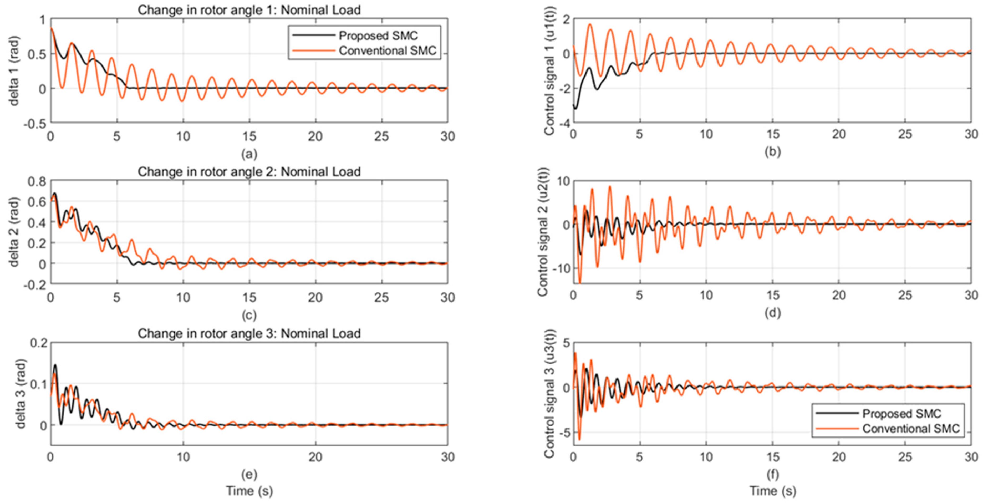
  • The theoretical conclusions are validated by the simulation results on a multi-machine IEEE test system.

1.3. Notations

Standard notations are used. (.)′ indicates the transpose of a vector or matrix. A symmetric positive (negative) definite matrix is denoted by p > 0 (< 0). (M + N + ∗) is the notation for (M + N + M′ + N′). Furthermore, the symbol (*) in a matrix denotes the symmetric portion, i.e., M N * Z   means   M N N Z . The symbols 0 and I stand for the zero matrix and the identity matrix, respectively. The time derivative of x is denoted by x . .
The order of the paper is as follows. The earlier research on power system stabilization is presented in Section 1. The system modeling and problem are formulated in Section 2. The ellipsoid approach of state feedback sliding mode control design is shown in Section 3. Results of a benchmark example simulation are provided in Section 4. Section 5 contains the conclusions.

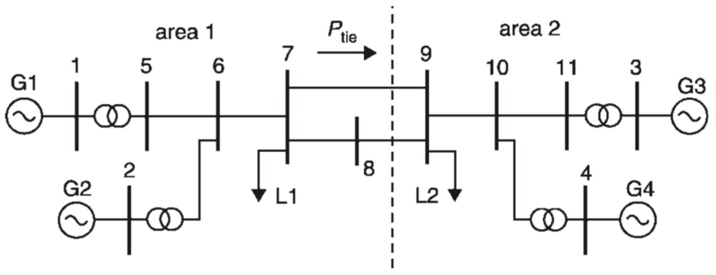
2. Power System Model and Problem Formulation

For small perturbations, the dynamics of an N+1 machine system (with machine#N+1 taken as a reference) can be linearized around an operating point. The dynamics of the rest N machines can be modeled by the state equation
x ˙ ^ = A ^ x ^ + B ^ u ^
The selected test system is the four-machine, 11-bus two-area IEEE test power system, Figure 1. The test system has two completely symmetrical areas connected by two 230 kV transmission lines spanning 220 km. Every region is furnished with two identical round rotor generators, each having a rating of 20 KV/900 MVA. The synchronous machines possess similar characteristics, with the exception of their inertia. In Area 1, the inertia is H = 6.5 s, whereas in Area 2 it is H = 6.175 s. The loads are shown as constant impedances and distributed across the two sections, as seen in Figure 1. The complete parameters are provided in [1].
For the benchmark system N + 1 = 4, with machine # 4 taken as the reference, the dynamics of the three rest machines, Equation (1) becomes x ^ = x 1 x 2 x 3 , similarly   for u ^ = u 1 u 2 u 3 . The state vector and the control input of each machine is δ w E q and E f , respectively . Where Δδ: rotor-angle deviation, rad, Δω: speed deviation, pu, ΔEq′,: deviation in the quadrature axis transient voltage, pu, ΔEf: deviations in the field voltage, pu.
The matrices A ^ = A 1 A 12 A 13 A 21 A 2 A 23 A 31 A 32 A 3 , B ^ = block   diag B 1 B 2 B 3 The numerical values of the above matrices are given in Appendix A. To achieve control decentralization, system (1) is split into three subsystems, and the dynamics for each are as follows:
x ˙ = A x + B u + D w , x 0 = x 0 , w = x ^ ,
Note that, for a particular subsystem, the impact of the rest on it is considered an external disturbance whose effect has to be attenuated. For machine# i, i = 1, 2, …N, (N = three machines in our case)
A = A i , B = B i , D = D i = A i 1 A i 2 0 i i . A i N , w = x ^
where for each machine x(t), u(t), w(t) are the state, control input, and the external disturbance vectors of dimension n, m, and k (k = n. N) respectively. The pairs (A, B), and (A, C) are assumed to be controllable and observable respectively. The disturbance is unknown but bounded as follows:
w Q w w w 0 + x Q x x
where the positive definite matrices Qw, Qx, and positive scalar w0 are given.
Note that the external disturbance for power systems is unmatched (the matrix D does not lie in the range (B, i.e., DB.Φ, Φ = any matrix).
The decentralized state feedback control for each machine using its local states is
u = K x
The controller gain K must be designed to stabilize the benchmark system subject to the constraint (3). SMC is selected for the controller (4) because of its paramount robustness against system uncertainties.

3. SMC by the Invariant Ellipsoid Method

The invariant ellipsoid method is a recently developed robust control method [9]. The method stabilizes linear and a class of nonlinear systems against plant uncertainties and attenuates the external disturbance effects. It has many applications, e.g., microgrids control [21] and synchronous motor position control [22].
The structure of SMC to stabilize perturbed systems is [23]
u t = ( C ~ B ) 1 C ~ A x t M x t . sign C ~ x t , M x t > 0
Here, the matrix C ~ ∈ Rm×n is a sliding surface such that det( C ~ B ) 0 and the positive control gain function M (x ) has the form
M x = α + x R x ,
where the scalar α and the positive definite matrix R are bounded control parameters as α < αmax, ‖R‖ ≤ β, α, β are scalars > 0. Such control can eliminate the disturbance if it lies in the range (B) and the is termed matched disturbance.
In power systems, the matching condition is not satisfied. In this scenario, the system (2) may have mismatched disturbances which cannot be suppressed using the traditional sliding mode control method. So, the primary challenge is creating a sliding mode control that uses the invariant ellipsoid approach to reduce (in a sense) the impacts of the unmatched disturbance [9].

3.1. Invariant Ellipsoid Method [9]

Definition 1.
The ellipsoid
E ( P ) = x R n : x P 1 x < 1 , P > 0
If any state trajectory of the system initialed inside the ellipsoid remains inside it for all time instants t > 0, then the ellipsoid centered at the origin with a configuration matrix P is said to be state-invariant for the system (2) with the disturbances (3); however, a trajectory starting outside the ellipsoid is attracted to this ellipsoid as time evolves (so the term attracting ellipsoid). Note that the Lyapunov function in (7) is so selected to allow for obtaining the ellipsoidal design of the proposed control, as will be seen later.
One way to think about the invariant ellipsoid is as a feature of how unmatched perturbations (3) affect the system (2). The smallest (in a sense) invariant ellipsoid (7) in the SMC application offers a “minimum deviation of any possible trajectory from the origin in a sliding mode”. The primary issue under consideration is creating a control that will allow any system (2) trajectory to converge into the previously established “minimum invariant ellipsoid”. For these kinds of optimization problems, the standard criterion is minimal tr(P−1). The sum of the squares of the semi-axes of the ellipsoid is described by the trace of the matrix P−1.
The invariant ellipsoid for the linear disturbed control system (using the Linear Matrix Inequalities optimization) is used to obtain an appropriate sliding surface C ~ x = 0 , [9].

3.2. System Decomposition and Main Result

Since rank(B) = m, the matrix B can be decomposed as follows:
B = B 1 B 2
where the dimensions of B1, B2 are (n−m).m, and m. m, respectively, with det(B2) 0 . In this case, there exists the nonsingular transformation [24]
x 1 x 2 = G x , where   G = I n m B 1 B 2 1 0 B 2 1
That reduces system (2) to the form
x ˙ 1 = A 11 x 1 + A 12 x 2 + D 1 w   x ˙ 2 = A 21 x 2 + A 22 x 2 + u + D 2 w
where the dimensions of x1, x2, are n−m, and m respectively. The matrices A11..A22 are of appropriate dimensions, and there should be no confusion with those given in the Appendix. Hence
A 11 A 12 A 21 A 22 = G A G 1 and D 1 D 2 = G D
where the dimensions of D1, and D2 are (n−m).k, and m.k respectively. Note that if the system (2) is controllable, then {A11, A12} is also controllable [24]. The following theorem is derived in [9]
Theorem 1.
The solution  α ,   τ ,   δ ,   L ,   Y ,   X ,   Z  of the minimization problem
m i n i m i z e   t r a c e ( Z )
Subject to the following inequality constraints
β 2 I n * R I n 0 , R α w 0 Q x , 0 < α α m a x ,
( A 11 X A 12 Y + * ) + τ X * * D 1 τ w 0 Q w * X Y 0 w 0 τ Q x 1 < 0 , X * X Y G Z G 0 , α w 0 Q w * G D δ . X * 0 L > 0 , 1 δ X * Y I m L 0
The solution of the above theorem provides the system’s minimum invariant ellipsoid (7). Moreover, the SMC is given by (5), (6), where the sliding surface is C ~ = Y X 1 , I m G . The above minimization problem can be solved using any gradient-free algorithm, e.g., the particle swarm optimization.
The above theorem is solved using the MATLAB LMI toolbox, yalmip interface, and sedumi solvers [25,26,27] (assuming α m a x = 100 , β m a x = 7 , Q w 0 = I , Q x = I , w 0 = 0.1 ) to obtain the decentralized excitation control with the sliding surfaces in Table 1. The MATLAB LMI toolbox is selected for solving the above optimization because it is the easiest and most productive software environment for engineers and scientists. For each machine, u(t) is the scalar sliding mode controller of the form (5).
Note that the merits of the proposed decentralized control are not without a price. The severity of decentralization constraint may result in an infeasible solution to the above LMI optimization problem. However, this does not imply system instability because the theorem’s condition is only sufficient.

4. Simulation Validation

The simulation results are provided to verify the effectiveness and resilience of the suggested technique in a comparison analysis conducted utilizing a conventional sliding mode excitation control. All simulation results were performed in MATLAB using the ode23 solver with a relative tolerance of 10−3. To avoid the chattering effect, the sign function in (5) is substituted by a saturation function [24].

4.1. Simulation of Multi-Machine Power System

To verify the improvement in stability resulting from the suggested stabilizer, a cleared three-phase fault test is conducted which results in rotor-angle deviation x0 = [0.87, 0, 0,0.6, 0, 0, 0.07, 0, 0]’.
The following three scenarios of operation were examined: the condition of a normal load, a light load, and a heavy load. Once the fault is cleared, the controller efficiently facilitates the system in rapidly attaining a stable operational state.
At nominal load, Figure 2 shows that the suggested approach provides superior control performance than conventional SMC in terms of settling time and damping effect. The proposed SMC also provides oscillations of fewer magnitudes and frequencies than the conventional SMC. This results in less fatigue and longer life for the generators’ rotors. Note that the control signal of the proposed design does not violate the permissible range, ±5 p.u, whereas the conventional signal does.

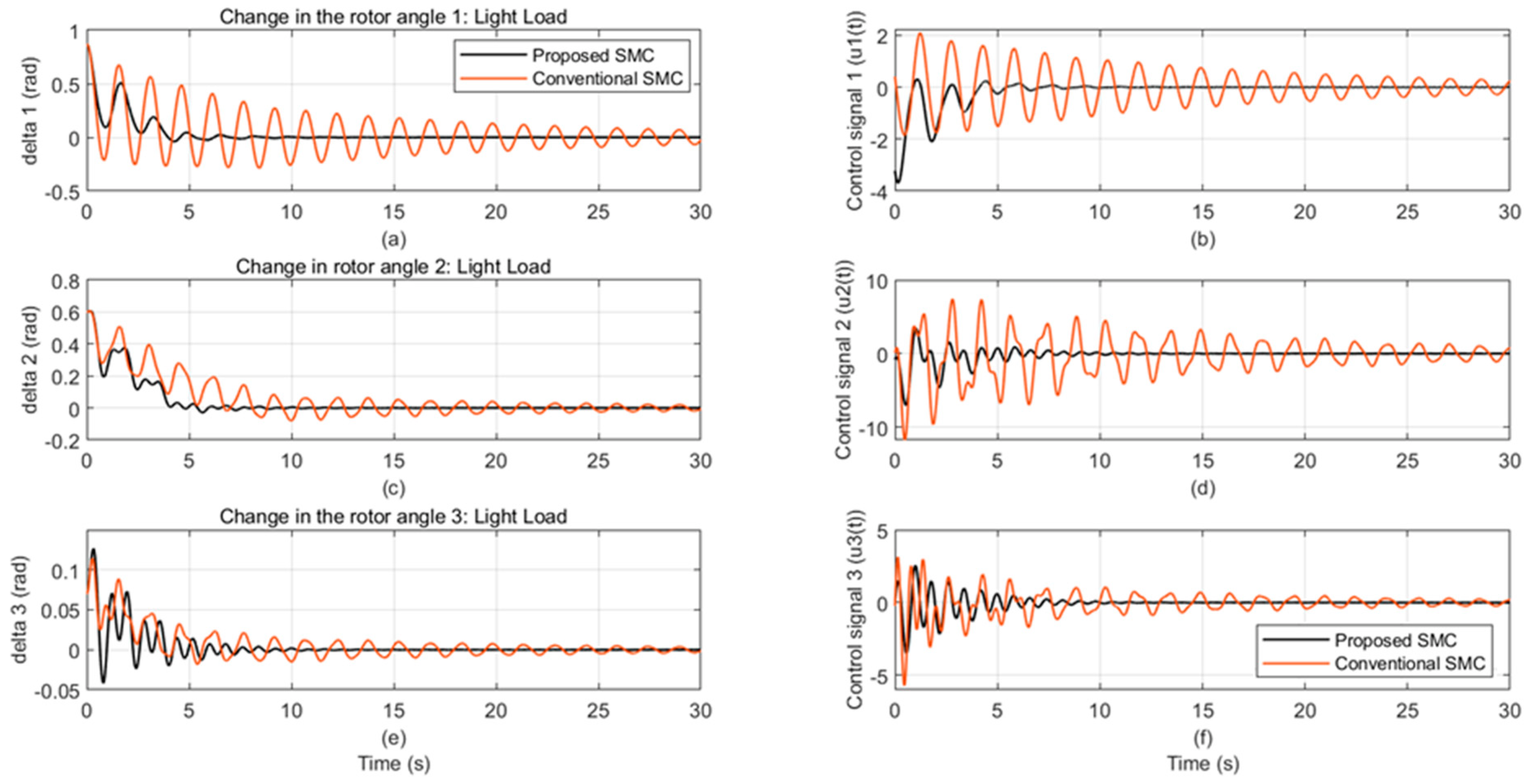
4.2. Robustness Assessment

To assess the robustness of the suggested stabilizer, the power system is tested during heavy load operation (Figure 3) and light load operation (Figure 4). These tests demonstrate the improved performance of the proposed controller in a multi-machine power system compared to the traditional SMC controller.
This article utilizes several operating points to showcase the efficacy of the suggested control method in mitigating oscillations after a significant disturbance on a power system. The proposed control method offers improved transient response and enhanced resilience compared to traditional sliding mode control (SMC).
Note that the above simulations show the superiority of the proposed SMC stabilization against unmatched disturbances over the conventional one. The idea of the ellipsoidal SMC is to force the state trajectory x(t) to be attracted to a very small region (min ellipsoid volume) around the origin and for x(t) to remain despite the existence of the external disturbance.

5. Conclusions

This paper presents an innovative control approach for a decentralized power system excitation control. Control decentralization is carried out by splitting the global system into subsystems; for each subsystem, a controller is installed which uses its local states. The effect of the rest of the system on a particular machine is considered as an external disturbance, the effect of which must be minimized. The design is based on the SMC with the invariant-ellipsoid method to attenuate the effects of unmatched external disturbances. The effectiveness of the proposed control method is illustrated with simulations of the IEEE test power system. Different loading conditions are utilized to evaluate the proposed decentralized excitation SMC efficiency, demonstrating superior performance to conventional SMC.
For future work, the applicability of the proposed method to handle unbalanced conditions and dampen oscillations in decentralized power systems is under investigation. Note that the stabilization of distributed generators under unbalanced conditions is given in [28].

Author Contributions

Methodology, H.M.S. and E.H.E.B.; software, H.M.S. and E.H.E.B.; validation, H.M.S. and F.A.E.-S.; data curation, E.H.E.B. and F.A.E.-S.; writing—review and editing, H.M.S., E.H.E.B. and F.A.E.-S.; visualization, F.A.E.-S.; supervision, H.M.S. and E.H.E.B. All authors have read and agreed to the published version of the manuscript.

Funding

This research received no external funding.

Data Availability Statement

The original contributions presented in the study are included in the article, further inquiries can be directed to the corresponding author.

Conflicts of Interest

The authors declare no conflicts of interest.

Appendix A. The Multi-Machine Model

The benchmark state equations at nominal load (tie-line power = 415 MW) is
(i)
Machine # 1
A 1 = 0 377 0 0.045693   0 0.089833   0.14728   0 0.32082   , B 1 = 0 0 0.125 D 1 = 0 A 12 A 13
where, A 12 = 0 0 0 0.045365 0 0.0031733 0.11398 0 0.10123 , A 13 = 0 0 0 0.0026 0 0.0126 0.0082 0 0.0085
(ii)
Machine # 2
A 2 = 0 377 0 0.0626 0 0.1129   0.1597   0 0.3632   , B 2 = 0 0 0.125 D 2 = A 21 0 A 23
where, A 21 = 0 0 0 0.0566 0 0.0237 0.1024 0 0.1304 , A 23 = 0 0 0 0.001 0 0.0129 0.0169 0 0.0017
(iii)
Machine # 3
A 3 = 0 377 0 0.094 0 0.1194   0.2056   0 0.4063   , B 3 = 0 0 0.125 D 3 = A 31 A 32 0
where, A 31 = 0 0 0 0.0107 0 0.0028 0.0183 0 0.0171 , A 32 = 0 0 0 0.0106 0 . 0002 0.024 0 0.0212 .

References

  1. Kundur, P.; Balu, N.J.; Lauby, M.G. Power System Stability and Control; McGraw-Hill Education: New York, NY, USA, 1994; Volume 7. [Google Scholar]
  2. Soliman, H.M.; Benzaouia, A.; El-Sheikhi, F.A.; Buyukatak, K. Grid Frequency Stabilization under Magnitude and Generation Rate Constraints. Int. J. Model. Identif. Control. 2024, 44, 174–180. [Google Scholar] [CrossRef]
  3. Sauer, P.W.; Pai, M.A.; Chow, J.H. Power System Dynamics and Stability: With Synchro phasor Measurement and Power System Toolbox; Wiley: Hoboken, NJ, USA, 2017. [Google Scholar]
  4. Dudgeon, G.J.W.; Leithead, W.E.; Dysko, A.; O’Reilly, J.; McDonald, J.R. The effective role of AVR and PSS in power systems: Frequency response analysis. Power Syst. IEEE Trans. 2007, 22, 1986–1994. [Google Scholar] [CrossRef]
  5. Mrad, F.; Karaki, S.; Copti, B. An adaptive fuzzy-synchronous machine stabilize. IEEE Trans. Syst. Man Cybern. Part C Appl. Rev. 2000, 30, 131–137. [Google Scholar] [CrossRef]
  6. Sarkar, D.U.; Prakash, T. A Recent Review on Approaches to Design Power System Stabilizers: Status, Challenges and Future Scope. IEEE Access 2023, 11, 34044–34061. [Google Scholar] [CrossRef]
  7. Rigatos, G.; Siano, P. Design of robust electric power system stabilizers using Kharitonov’s theorem. Math. Comput. Simul. 2011, 82, 181–191. [Google Scholar] [CrossRef]
  8. Garcia-Sanz, M.; Houpis, C.H. Wind Energy Systems: Control Engineering Design; CRC Press: Boca Raton, FL, USA, 2012. [Google Scholar]
  9. Poznyak, A.; Polyakov, A.; Azhmyakov, V. Attractive Ellipsoids in Robust Control; Springer: Cham, Switzerland, 2014. [Google Scholar]
  10. Boukas, E.; AL-Sunni, F.M. Mechatronic Systems Analysis, Design and Implementation; Springer: Berlin/Heidelberg, Germany, 2011. [Google Scholar]
  11. Yaghooti, A.; Buygi, M.O.; Shanechi, M.H.M. Designing coordinated power system stabilizers: A reference model based controller design. IEEE Trans Power Syst. 2016, 31, 1–11. [Google Scholar] [CrossRef]
  12. Abido, M.A.; Abdel-Magid, Y.L. Optimal design of power system stabilizers using evolutionary programming. IEEE Trans. Energy Con. 2002, 17, 429–436. [Google Scholar] [CrossRef]
  13. Sarkar, D.U.; Prakash, T. A Neural Network Approach to Design Power System Stabilizer for Damping Power Oscillations. In Proceedings of the 22nd National Power Systems Conference (NPSC), New Delhi, India, 17–19 December 2022. [Google Scholar]
  14. Hussein, T.; Saad, M.S.; Elshafei, A.L.; Bahgat, A. Damping inter-area modes of oscillation using an adaptive fuzzy power system stabilizer. Electr. Power Syst. Res. Dec. 2010, 80, 1428–1436. [Google Scholar] [CrossRef]
  15. Saoudi, K.; Harmas, M.N. Enhanced design of an indirect adaptive fuzzy sliding mode power system stabilizer for multi-machine power systems. I.J. Electr. Power Energy Syst. 2014, 54, 425–443. [Google Scholar] [CrossRef]
  16. Ju, P. Stochastic Dynamics of Power Systems; Springer: Berlin/Heidelberg, Germany, 2019. [Google Scholar]
  17. Ye, K.; Zhao, J.; Duan, N.; Maldonado, D.A. Stochastic Power System Dynamic Simulation and Stability Assessment Considering Dynamics from Correlated Loads and PVs. IEEE Trans. Ind. Appl. 2022, 58, 7764–7775. [Google Scholar] [CrossRef]
  18. Lu, Z.; Lu, S.; Xu, M.; Cui, B. A robust stochastic stability analysis approach for power system considering wind speed prediction error based on Markov model. Comput. Stand. Interfaces 2021, 75, 103503. [Google Scholar] [CrossRef]
  19. Poznyak, A.S.; Alazki, H.; Soliman, H.M. Invariant-set Design of Observer-based Robust Control for Power Systems Under Stochastic Topology and Parameters Changes. I. J. Electr. Power Energy Syst. 2021, 131, 107112. [Google Scholar] [CrossRef]
  20. Poznyak, A.; Alazk, H.; Soliman, H. Attractive ellipsoidal design for robust stabilization of time-delay stochastic power systems under a series of lightning surges. Comput. Electr. Eng. 2024, 116, 109228. [Google Scholar] [CrossRef]
  21. Poznyak, A.S.; Soliman, H.M.; Alazki, H.; Bayoumi, E.H.E.; De Santis, M. Decentralized passivity-based voltage tracker for islanded DC-microgrids: Attracting ellipsoid approach. Energies 2024, 17, 1529. [Google Scholar] [CrossRef]
  22. Bayoumi, E.H.E. Sliding Mode Position Control of Synchronous Motor with Parameters and Load Uncertainties. Electromotion Sci. J. 2010, 17, 99–106. [Google Scholar]
  23. Edwards, C.; Spergeon, S. Sliding Mode Control: Theory and Applications; Taylor and Francis: Abingdon, UK, 1998. [Google Scholar]
  24. Utkin, V.I.; Guldner, J.; Shi, J. Sliding Modes in Electromechanical Systems; Taylor and Francis: London, UK, 1999. [Google Scholar]
  25. The MathWorks Inc. MATLAB, Version: 9.13.0 (R2023b); The MathWorks Inc.: Natick, Massachusetts, 2023; Available online: https://www.mathworks.com (accessed on 2 August 2024).
  26. Available online: https://yalmip.github.io/ (accessed on 19 August 2024).
  27. Available online: https://sedumi.ie.lehigh.edu/?page_id=58 (accessed on 19 August 2024).
  28. Jin, P.; Li, Y.; Li, G.; Chen, Z.; Zhai, X. Optimized hierarchical power oscillations control for distributed generation under unbalanced conditions. Appl. Energy 2017, 194, 343–352. [Google Scholar] [CrossRef]
Figure 1. IEEE Two-areas four-machines, 11-bus test power system.
Energies 17 04249 g001
Figure 2. Rotor-angle deviations and control input in nominal load case. (a,b) rotor angle and control signal of machine 1 respectively, (c,d) rotor angle and control signal of machine 2 respectively, (e,f) rotor angle and control signal of machine 3 respectively.
Energies 17 04249 g002
Figure 3. Rotor-angle deviations and control input in heavy load case. (a,b) rotor angle and control signal of machine 1 respectively, (c,d) rotor angle and control signal of machine 2 respectively, (e,f) rotor angle and control signal of machine 3 respectively.
Energies 17 04249 g003
Figure 4. Rotor-angle deviations and control input in light load case. (a,b) rotor angle and control signal of machine 1 respectively, (c,d) rotor angle and control signal of machine 2 respectively, (e,f) rotor angle and control signal of machine 3 respectively.
Energies 17 04249 g004
Table 1. Proposed design.
Machine # α R Sliding   surface   C ~
10.6592[6.8119, −1.0325 × 10⁻¹³, 6.6887 × 10⁻¹³
−1.0325 × 10⁻¹³, 6.8119, −7.6312 × 10⁻¹³
6.6887 × 10⁻¹³, −7.6312 × 10⁻¹³, 6.8119]
[−0.98782 −99.5610 8]
20.58687[6.4499, 6.4696 × 10⁻¹³, 8.0441 × 10⁻¹³
6.4696 × 10⁻¹³, 6.4499, −4.0267 × 10⁻¹³
8.0441 × 10⁻¹³, −4.0267 × 10⁻¹³, 6.4499]
[−24.71 −42.9985 8]
30.63266[6.6725, 2.7361 × 10⁻¹², −7.2498 × 10⁻¹²
2.7361 × 10⁻¹², 6.6725, −3.1488 × 10⁻¹²
−7.2498 × 10⁻¹², −3.1488 × 10⁻¹², 6.6725]
[−72.22 −109.310 8]
Disclaimer/Publisher’s Note: The statements, opinions and data contained in all publications are solely those of the individual author(s) and contributor(s) and not of MDPI and/or the editor(s). MDPI and/or the editor(s) disclaim responsibility for any injury to people or property resulting from any ideas, methods, instructions or products referred to in the content.

