Review

CCUS Perspectives: Assessing Historical Contexts, Current Realities, and Future Prospects

by
William Ampomah
1,*,
Anthony Morgan
1,2,*,
Desmond Ofori Koranteng
1 and
Warden Ivan Nyamekye
2
1
New Mexico Tech, Petroleum Recovery and Research Center, Socorro, NM 87801, USA
2
Petroleum and Natural Gas Department, University of Energy and Natural Resources, Sunyani P.O. Box 214, Ghana
*
Authors to whom correspondence should be addressed.
Energies 2024, 17(17), 4248; https://doi.org/10.3390/en17174248
Submission received: 6 August 2024 / Revised: 19 August 2024 / Accepted: 20 August 2024 / Published: 25 August 2024
(This article belongs to the Special Issue Forecasting CO2 Sequestration with Enhanced Oil Recovery II)

Abstract

:
CCUS technologies are crucial solutions for mitigating climate change by reducing CO2 emissions from industrial operations and energy sectors. This review critically examines the current state of CCUS technologies, and highlights advancements, challenges, regulatory frameworks, and future directions. It comprehensively analyzes carbon capture methods, such as pre-combustion, post-combustion, and oxy-fuel combustion capture, while comparing their efficiencies and limitations. The review also explores carbon utilization techniques, such as direct and indirect utilization, emphasizing their potential applications and technological constraints. Additionally, it assesses various carbon storage methods, focusing on geological, ocean, and mineralization storage, and discusses their capacity, feasibility, and environmental implications. The study reviews the policy and regulatory frameworks, economic viability, market trends, and environmental sustainability of CCUS. By identifying research gaps and recommending future research priorities, this review aims to guide the development of more efficient/effective, and cost-effective CCUS technology, ensuring their role in a sustaining low-carbon future. This review provides a forward-looking perspective, a critical and interdisciplinary analysis that assesses the current state of CCUS technologies, and further provides a roadmap for future development.

1. Background and Significance of CCUS

Burning carbon-based fuels for energy generation and industrial operations is a significant contributor to the rise in atmospheric CO2 levels, which leads to global warming and climate change [1,2,3]. The principle behind global warming is the greenhouse effect (Figure 1), a natural process that regulates the temperature of the Earth [4]. The Sun emits energy through sunlight, which reaches the Earth’s atmosphere. A proportion of sun rays reaching the Earth are absorbed and reemitted to the atmosphere as infrared radiations (heat). Greenhouse gases (GHG) in the atmosphere, such as carbon dioxide (CO2), methane (CH4), water vapor, and nitrous oxide (N2O), trap these radiations, which prevents their escape back to space. This warms the Earth, making it conducive for life. An increase in GHG leads to an enhanced greenhouse effect, intensifying heat-trapping and hence, a rise in global temperatures (i.e., global warming) [1,5]. Global warming has consequences, including intensified heat waves, altered precipitation patterns, melting polar ice caps, and disruption to ecosystems and biodiversity. These impacts significantly challenge human societies, economies, and the natural environment.

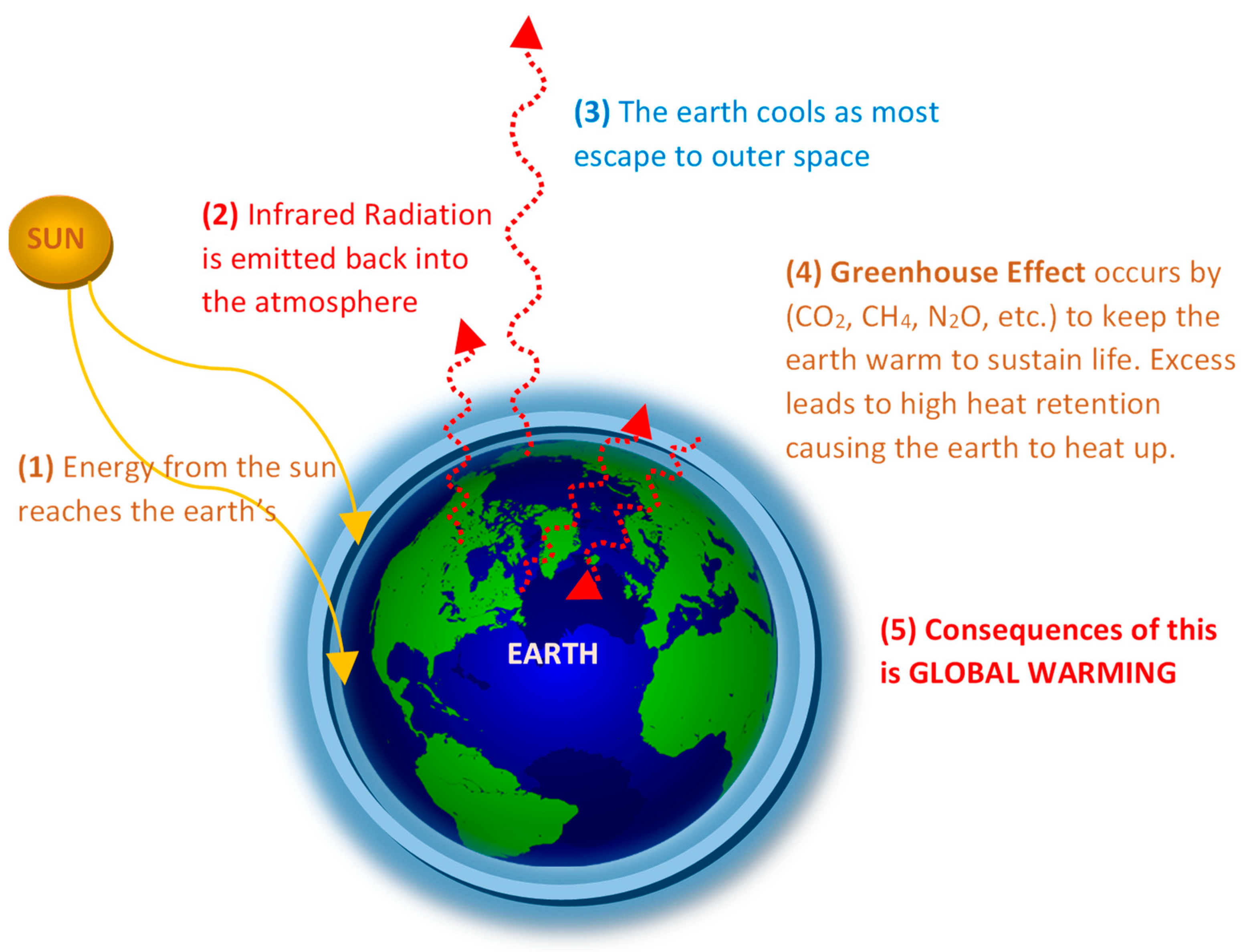
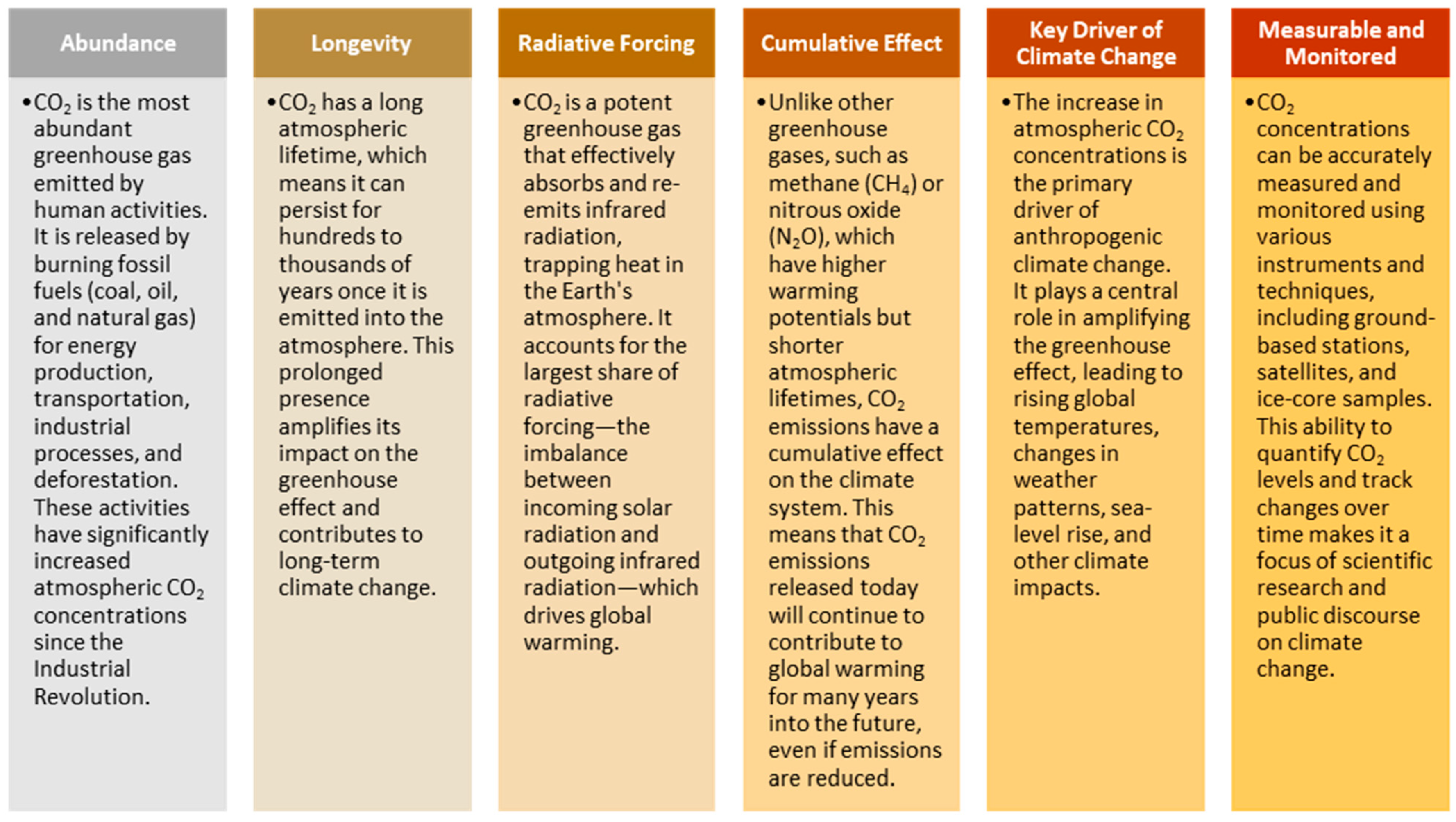
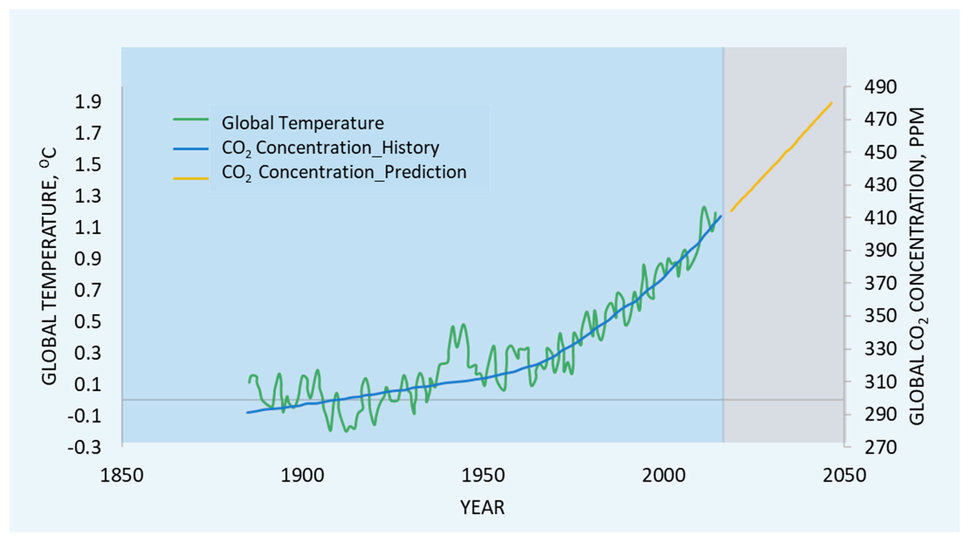
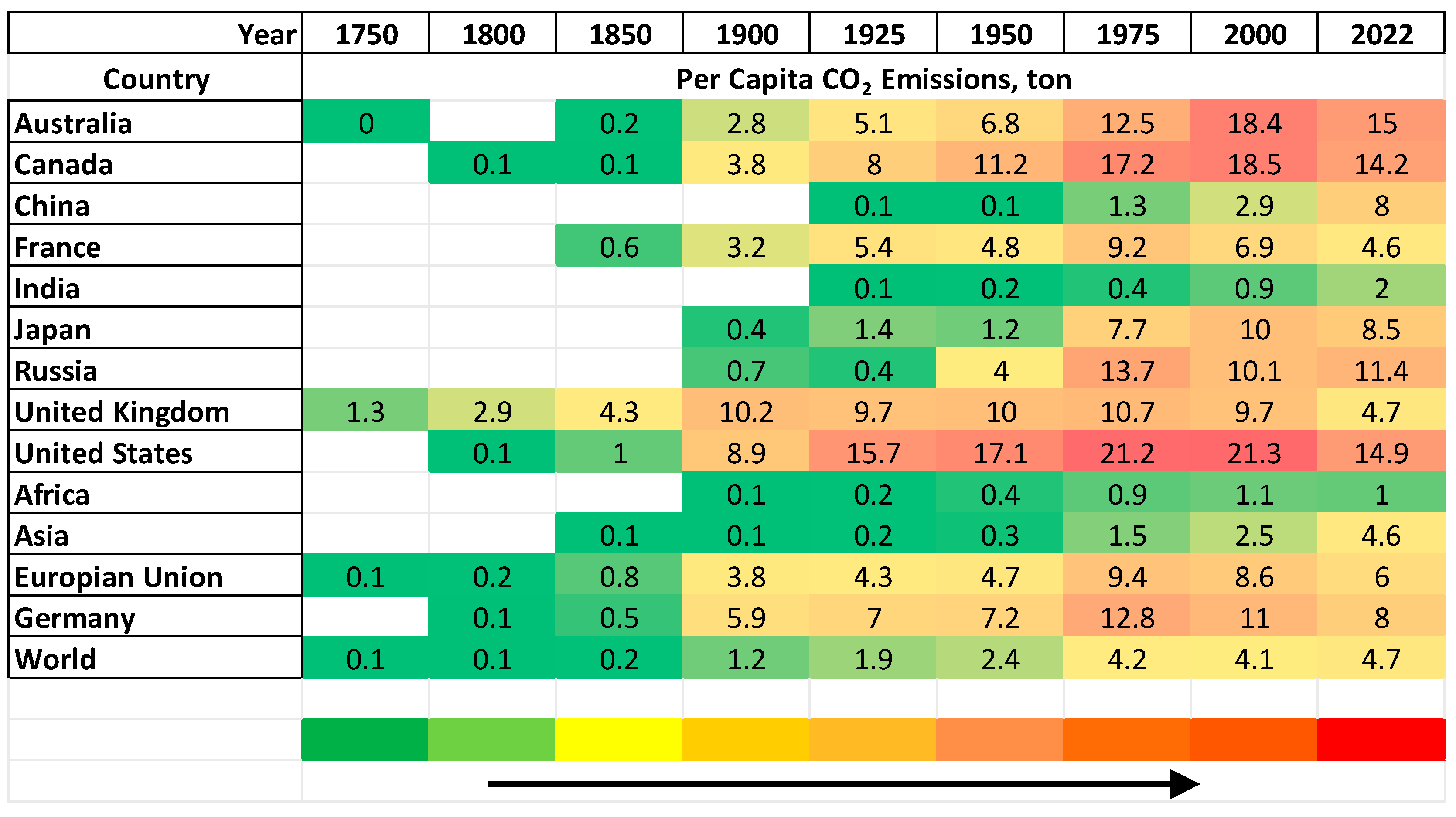
1.1. CO2 as a Key Target in Global Warming Menace

Among the various GHGs, CO2 is often singled out in global warming and climate change discussions. The Intergovernmental Panel on Climate Change (IPCC, 2018) [6] elaborated key factors that elucidate the strong influence of CO2, which is summarized in Figure 2. These include its abundance, longevity, radioactive forcing, and measurability. According to the latest data from the Mauna Loa Observatory, atmospheric CO2 concentrations have risen steadily since the Industrial Revolution [7]. In 2020, the global average atmospheric CO2 concentration rose to a record high of 414.8 ppm (Figure 3), representing an alarming rise compared to pre-industrial levels (280 ppm) [8]. IPCC estimates that CO2 contributes approximately 60% of the total radiative forcing, driving global warming since 1750 [6,9].
The impact of rising CO2 levels on global temperatures is evident in long-term temperature records. According to the National Oceanic and Atmospheric Administration (NOAA), the global temperature, on average, has risen by 1.2 °C (2.2 °F) above pre-industrial levels, with the past decade (2011–2020) being the warmest on record [10] (Figure 3). This is expected to rise per estimates by climate surveys to 5.8 °C [11,12]. The relationship between CO2 emissions and global warming is further exacerbated by feedback mechanisms, such as the ice–albedo feedback and the release of more greenhouse gases (e.g., methane) from thawing permafrost. These feedback loops amplify the warming effect of CO2 emissions, contributing to accelerated climate change [6,13]. Rising CO2 levels are associated with increased climate extremes, including more frequent and intense heat waves, extreme precipitation, and melting polar ice caps. These impacts have far-reaching consequences for ecosystems, human health, agriculture, and infrastructure [10]. IPCC, the Paris Climate Agreement (PCA), resolved that efforts need to be implemented to limit atmospheric temperatures below 2 °C (storage of about 10 × 109 tons by 2050 and over 20 × 109 by the end of the century) [13]; thus, according to IEA, 2021, achieving net-zero emissions by mid-century (2050) is the way to go, to curtail global warming and its adverse impact [14]. Alternative sources of energy, mainly green energy (solar, wind, etc.) by IEA, 2021, are proposed to be advanced by about twentyfold to near the net-zero emissions target by 2050. Together with carbon capture, utilization, and sequestration, CO2 concentrations in the atmosphere by the year 2100 can be maintained at 450 ppm, which will roughly lower global temperatures below 2 °C [6,11]. To address this pressing issue, CCUS has gained attention as a promising technology for reducing CO2 emissions from various point sources, such as power plants, refineries, chemical processing plants, and cement factories.
Carbon capture involves the capture of CO2 released from industrial operations or directly from the atmosphere to prevent atmospheric emissions. The CO2 can then be transported to be utilized in various applications, such as enhanced oil recovery, production of synthetic fuels, or chemical manufacturing through carbon utilization techniques. Additionally, carbon storage involves safely storing CO2 in geological formations or other suitable reservoirs to prevent its return to the atmosphere. The significance of CCUS lies in its potential to feasibly reduce GHG emissions by seventeen percent by 2050 by annually capturing and storing about 5.6 gigatons with the continual use of carbon-based fuel during the transition to a low-carbon economy [14]. This requires a yearly addition of about 75 to 150 capture facilities globally, as indicated by the IEA Greenhouse Gas Research and Development Program [11]. Furthermore, CCUS can be crucial in achieving climate targets outlined in international agreements such as the Paris Agreement [15].
Currently, based on the rate of CCUS projects being established or developed, it is estimated that about 10% of the projected storage goals can be achieved by 2050 [6,11]. Implementing clean energies and efficient energy management are sure ways of reaching net-zero emissions. However, the fast rate of industrialization, high energy demand, and population growth have resulted in an uncontrollable rise in emissions, as observed in the per capita CO2 emissions estimates by the Global Carbon Budget, 2023 (Figure 4) [16]. CCUS presents a much more plausible approach to meet the targeted emission goals by mid-century. Though CCUS may sound quite simple, implementation may be sophisticated and delayed due to factors ranging from high capital and operational costs, technical complexities, land and pore space access, regulatory uncertainties, and public acceptance issues due to environmental and safety risks. Thus, the availability of well-collated and digested information and data on the historical contexts, current realities, future prospects, synergies, and inherent gaps is crucial for the efficient and effective deployment of CCUS projects.

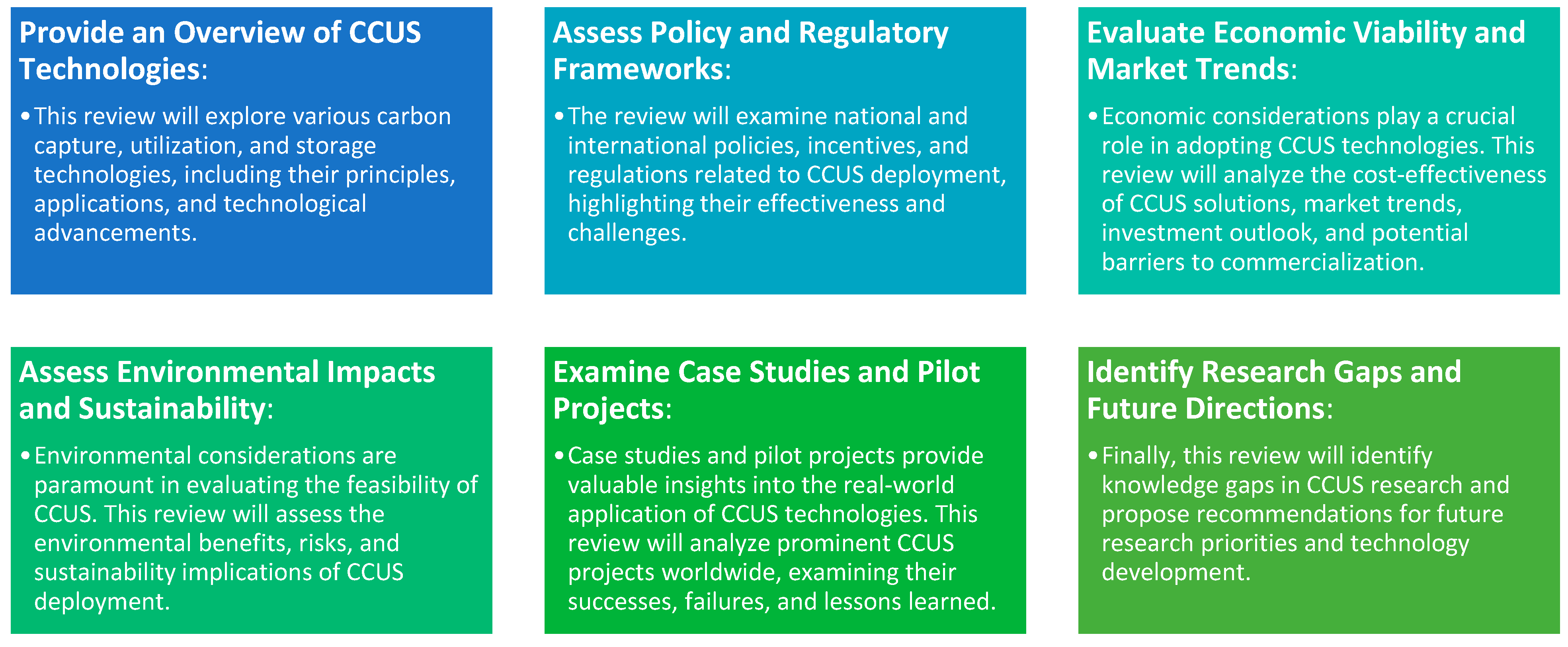
1.2. Scope and Objectives

This review critically analyzes the existing research and literature on CCUS technologies, policies, and practices. By synthesizing and evaluating a wide range of scholarly articles, reports, and case studies, it aims to provide insights into the current state of CCUS, identify key challenges and opportunities, and propose recommendations for future research and implementation. Through a comprehensive examination of the literature, this review seeks to address the following key objectives (Figure 5):
Thus, the review seeks to present further insights on CCUS to add to knowledge by providing detailed information on the outlined objectives. This review stands out from previous publications on CCUS based on its holistic analysis covering a broad spectrum of CCUS (Figure 5). A critical qualitative and quantitative evaluation of technological advancements and a comparison of their efficiencies, limitations, and technological constraints is essential to identify bottlenecks and potential areas for improvement. The review also provides an interdisciplinary focus, by assessing policies and regulatory frameworks, economic viability, and market trends and, further, goes beyond the technical aspects by incorporating socioeconomic and environmental dimensions. Through a review of existing CCUS projects, this review also systematically identifies research gaps and provides direct recommendations for future research directives. This knowledge base will help inform policy and decision-makers, industry stakeholders, researchers, and the general public and facilitate the accelerated deployment of CCUS technologies to mitigate climate change. This review, thus, provides a forward-looking perspective, a critical and interdisciplinary analysis that assesses the current state of CCUS technologies and further provides a roadmap for future developments.

2. Overview of Carbon Capture, Utilization, and Storage (CCUS)

The concept of CO2 capture and storage to mitigate climate change dates back to the late 20th century. In the 1970s and 1980s, researchers and policymakers began exploring the feasibility of CO2 from power plants and industrial outlets [9]. Carbon capture technologies accelerated in the late 20th century, with significant research and investment focused on post-combustion, pre-combustion, and oxyfuel combustion capture methods. One of the earliest large-scale CCUS projects was the Sleipner project in Norway, which commenced CO2 injection in 1996 into geological formations [17]. While early efforts primarily focused on capturing and storing CO2, carbon utilization gained traction around the 20th and 21st centuries. Research work focused on exploring various pathways for utilizing captured CO2, including enhanced oil recovery (EOR), chemical and material production, and carbonation or mineralization processes [18,19]. The development and deployment of CCUS technologies have been influenced by evolving policy and national and international regulatory frameworks. Initiatives such as the Kyoto Protocol and the Paris Agreement have highlighted the importance of CCUS in achieving climate mitigation goals and provided incentives and funding mechanisms to support CCUS projects [6]. These frameworks set a goal to store 125 gigatons of CO2 by the end of the century [13]. Despite significant progress, CCUS deployment has faced numerous challenges and barriers, including high costs, technical complexities, regulatory uncertainties, and public acceptance issues. The limited availability of suitable storage sites and concerns about environmental and safety risks have also hindered the widespread adoption of CCUS technologies [20]. Thus, for a successful and sustainable CCS project, a continuous supply and a reliable source of anthropogenic CO2 are required, as well as high-capacity storage sinks (depleted oil reservoirs, saline aquifers) to accommodate the amount of CO2 supply from close sources, favorable governmental legislation and regulation, and, most importantly, financial capacity.

2.1. Future Prospects and Strategic Directions in CCUS

In recent years, interest and investment in CCUS technologies have been renewed, driven by growing recognition of the urgent obligation to tackle climate change. Governments, industry stakeholders, and research institutions have collaborated on various demonstration projects and pilot initiatives to advance CCUS deployment and scale up technology deployment [14,21]. For CCUS to thrive in the future, it is crucial to continue developing technology, receiving policy support, and fostering international collaboration. Progress in carbon capture, utilization, and storage technologies, alongside supportive regulatory frameworks and market incentives, has the potential to expedite the deployment of CCUS and play a substantial role in global climate mitigation endeavors [11]. According to the Global CCS Institute, as of 2020, sixty-five large-scale CCUS facilities were in different levels of development globally, with over 40 million tonnes per annum (Mtpa) of CO2 capture capacity [22]. These projects span various sectors, including power generation, oil and gas production, and industrial manufacturing. One of the prominent examples of CCUS deployment is the Boundary Dam CCS project in Saskatchewan, Canada, which began operations in 2014. This involves underground anthropogenic CO2 storage captured from a coal-fired power plant, demonstrating the feasibility of large-scale CCUS implementation. An exhaustive list of notable CCUS projects, successful, underdeveloped, and unsuccessful or terminated projects worldwide are summarized in Table A1, Table A2 and Table A3 (Appendix A) with a brief description. There are about 800 sedimentary basins optimum for subterranean sequestration [23]. With the presence of the required capital and beginning with site selection, projects can take between 5 and 10 years to be established [24]. Some major social concerns that may pose hindrances to CCS acceptance include the risk of leakages into USDW, health issues, environmental degradation, and accidental events [6,11,25]. For a CCS project to be classified as large-scale, Global CCS Institutes define a cut of 400 Kt/year of anthropogenic CO2 captured and sequestered from industrial sources and 800 Kt/year from a coal-fired power station [11,22,24].

2.2. Harnessing CCUS Potential in Emerging Markets

CCUS has a vast resource potential, with ample opportunities for deployment across multiple sectors. According to the IEA, CCUS can minimize global CO2 emissions by up to 13% by 2050, compared to a scenario without CCUS implementation [26]. This potential is particularly significant in industrial sectors such as power generation, steel, iron, and cement production, and chemical industries, which are significant sources of CO2 emissions and biological respiration. Globally, photosynthesis and absorption through the environment are capable of reducing atmospheric CO2 by 15–20% [11,27,28]. One key aspect of CCUS resource potential lies in its ability to enable the continuous utilization of existing carbon-based fuel while reducing carbon emissions [3,29,30]. CCUS technologies can be integrated into existing carbon-based fuel infrastructure, such as coal-fired power plants and natural gas processing facilities, to capture CO2 emissions and avoid their release into the atmosphere [6]. This allows for the decarbonization of these industries without requiring immediate and extensive infrastructure changes. Furthermore, CCUS offers opportunities for CO2 utilization, where captured CO2 is converted into valuable products (e.g., chemicals, fuels, and building materials). This utilization aspect not only helps to reduce CO2 emissions but also creates economic value by generating revenue from CO2-derived products [14]. In addition to its mitigation potential, CCUS resource potential extends to the geological storage of CO2 in suitable underground formations, such as depleted oil and gas reservoirs, saline aquifers, and deep geological formations. These geological storage sites can securely store vast amounts of CO2 over long periods, preventing its release into the atmosphere and contributing to climate change mitigation [6]. Thus, CCS utilizes subsurface space, requiring less surface space. Land repurposed for CCS gives it a significant advantage over wind and solar plant installation [11]. Overall, CCUS technologies offer a versatile and practical approach to reducing CO2 emissions across various sectors, with significant resource potential for emission reduction and creating value-added products.

Current Underground Injection Control (UIC) Class VI Permit Applications

Regardless of the significance of CCS, injecting any form of fluid into the subsurface environment is strictly scrutinized and controlled. The U.S. EPA oversees multiple Class VI well permits under its UIC program. This program is designed to regulate CO2 injection into subsurface geologic formations for long-term storage, serving as one of the secured and feasible means for atmospheric CO2 reduction. As of April 2024, the EPA, to increase transparency and easy access to review processes and progress, released a comprehensive dashboard with an enhanced visualization of submitted program metrics that details the status of various UIC permit applications. As of June 2024, 139 Class VI well applications from 48 projects (Figure 6) were under review by the EPA regional office, with an additional 69 VI well applications from 33 under review in states with enforcement primacy (Louisiana, North Dakota, and Wyoming) [31,32,33]. This indicates the US’s proactiveness and global lead in combatting global warming through CCS.
The application for UIC Class VI involves comprehensive processes and stages to ensure safety and compliance with regulatory standards. This includes a pre-application consultation (initial meeting with EPA and preliminary site characterization), the Permit application submission (application form, comprehensive report on geological data, and definition and analysis of Area of Review (AOR)) [31]. This then goes through the technical review (EPA review and public comment or input), the risk management plan (submission of monitoring, reporting, and verification, MRV, and Emergency and remedial Response plan), and Financial Responsibility (detailed cost estimates and financial assurance). If all requirements are met, the EPA then goes through with the Permit decision (draft permit for public review and final permit), Post-permit issuance (operational phase begins and periodic review by EPA), and the final stage is the Post-injection and site closure after EPA or state authorities certify the site poses no risk [31].
The timeframe for issuance of Class VI permits depends hugely on the application process and the complexity and specifics of the project and application (i.e., project complexity, public and stakeholder engagements, and regulatory efficiency). There are Active Permits like Archer Daniels Midland Company (ADM), Illinois and the Wabash Carbon Services, LLC in Indiana, and Pending Permits like the carbon terraVault JV Company in California [34], which is still in the pre-construction phase (meaning a permit can be issued in one to two years depending on regulatory reviews and public consultation) [32,33]; thus, timeframe estimation can be based on initial technical reviews, which can last for several months to a year depending on the thoroughness required and the complexity of the geological data provided. Public comment periods and stakeholder engagements can add additional months to the process [31]. Additionally, there are state-specific timelines (states with enforcement primacy) with expedited procedures that could expedite permits quicker than those under EPA management [31]. Nonetheless, strict federal regulations are followed. Therefore, it is anticipated that most pending Class VI permits will be issued from their existing status within a year to three years. This estimate is consistent with the average duration in other intricate regulatory contexts, where thorough technical evaluations and public participation are essential elements of the procedure.

3. CCUS Pathways and Technological Advancement

The primary principles underlying CCUS involve capturing CO2, transporting it, utilizing it in productive ways, and safely storing it to mitigate climate change. According to the IEA, CCUS comprises the capture and transport of CO2 from sources such as, fossil fuel power generation operations for storage or utilization [26]. The four main components in the CCUS process are presented in Figure 7, the CCUS pathway.
Capture technologies employed include post-combustion, oxy-fuel combustion, or pre-combustion. Once captured, CO2 undergoes compression to reduce its volume and increase its density, making transporting over long distances more effortless and more cost-effective [29,35,36]. The transportation process is a vital component of the CCUS chain, facilitating the efficient and safe transfer of CO2 for storage or utilization. In the transport phase, pipelines are the most common means. CO2 pipelines, similar to natural gas pipelines, are specifically designed to handle CO2 and can transport high amounts of CO2 over considerable distances, connecting capture sites with storage or utilization sites [26]. When pipeline infrastructure is unavailable, CO2 may be transported via ships or tankers, primarily for oceanic transport or to remote areas. CO2 shipping involves storing the CO2 in specialized containers or tanks onboard ships and transporting it to its destination port [26]. Trucking is another method for CO2 transportation, particularly for shorter distances or areas without pipeline infrastructure. CO2 is loaded into trucks or tankers and transported to nearby storage or utilization sites [26]. Throughout the transportation process, stringent monitoring and safety measures are implemented to ensure the safe handling and transport of CO2. This includes monitoring CO2 flow rates, pressures, and concentrations and implementing leak detection systems and emergency response protocols to prevent and mitigate potential incidents [35]. Upon reaching the storage or utilization site, CO2 is either injected into suitable geological formations for storage, such as depleted oil and gas reservoirs or saline aquifers, or utilized for other economic benefits, such as EOR, manufacturing of chemicals, or production of building materials [26].

3.1. Carbon Capture and Separation Technologies

Technological advancement concerning the capture and separation of CO2 from the stream of flue gases is one of the most crucial and critical aspects of CCUS that dictates the economics and deployment of CCUS projects [28]. Fifty to ninety percent of the CCUS project cost is associated with capture systems [28,37]. Post-combustion, pre-combustion, and oxy-fuel combustion are the most matured and widely used capture technologies (Figure 8). Others include chemical looping combustion (CLC), industrial separation, and DAC systems.

3.1.1. Industrial Process

As of 2021, most commercial CCUS operations worldwide were connected to natural gas processing facilities with 30 Mt CO2 capture per annum. Industrial processes with high CO2 concentrations incurred about USD 10.00 to capture a tonne of CO2 [38]. The iron and steel industry generated about 2.6 Gt of CO2 in 2019; however, with this high emission, only one CCS plant was in operation, with one under development in this sector. In this technology, coal or natural gas are utilized as reducing agents, which generate elemental iron through the direct reduced iron unit (DRIU), which produces pure CO2 [28]. Another low-cost and low-carbon footprint iron production process that utilizes low-grade coal and produces CO2 and water vapor as a by-product is the COREX process [17,39]. Emitting about 2.5 Gt a year is the cement industry. Retrofitting with post-combustion and oxy-fuel can capture about 15–30% and 70% by volume in flue gas, respectively [14,40]. The Heidelberg Cement’s Norcem Brevik plant in Norway has this approach to capture about 0.4 Mt CO2/yr, as reported by [41]. LEILEC project for the cement and lime industry is developing a cost-effective capture technique inspired by the indirect calcination process (the Calix process). Another industrial example is the production of aluminum (about 3.5% of global electricity usage with 2.5 Mt CO2, through the Hall-Héroult process, which makes it difficult for CCS inclusion, (Figure 9) [42,43]. This is why an alternative approach is being researched, employing an inert anode from materials such as ceramic composite (undegradable and producing oxygen instead of carbon dioxide).

3.1.2. Post Combustion

In post-combustion (Figure 10), CO2 is captured from emitted flue gas (3% to 30% CO2, about 5 bar (72.5 psi) partial pressure [44]) emitted after combustion in industrial processes such as power generation or cement production. In this method, CO2 is separated from gases such as N2 and H2O vapor after combustion. Typically, the post-combustion technique uses solvents or sorbents to capture CO2 from the flue gas stream selectively. Due to its maturity, it is applicable to both existing and future power plants [24,28]. To reach a capture of about 95.5%, other compositions of flue gas (such as SO2, NOx, fly ash, trace metals, etc.) must be significantly reduced. This, however, increases the cost of capture [17]. The cost and performance associated with post-combustion may depend on the fuel source and process of CO2 generation. With an assumed capture efficiency of 90%, natural gas combined cycle (NGCC), and supercritical pulverized coal (SCPC) power plants, there is an average increment of about 18% and 44% electricity consumption, respectively [45]. With an estimated levelized cost of electricity for SCPC to be USD 192/MWh and USD 200/MWh for IGCC with post-combustion. Kheirinik et al. [37] stated that SCPC has low capital and indirect costs as compared to IGCC [28].

3.1.3. Pre-Combustion

Pre-combustion capture (Figure 10) involves capturing CO2 before the combustion of fossil fuels in industrial processes such as natural gas reforming or coal gasification. In pre-combustion capture, carbon base fuels are converted into syngas (CO and H mixtures predominantly converted into syngas (CO and H mixtures) before combustion [17]. The CO2 (usually between 15 and 60% by volume with an average pressure of about 4.5 MPa, which is high and makes separation effective with low energy demands) is then separated from the syngas stream before combustion (using the H2) occurs, usually through processes like pressure swing adsorption or physical absorption [46]. This matured technology in the chemical industry has been deployed for over 95 years [28]. Pre-combustion lowers energy consumption to about 10% for capture from bituminous coal, but with USD 83 per ton of CO2, it has a higher capture cost than supercritical pulverized coal plants [47].

3.1.4. Oxy-Fuel Combustion

Oxy-fuel combustion involves burning fossil fuels in about 95–99% purity oxygen instead of air at temperatures of about 1400 °C (gas turbines cycle) and 1900 °C (coal-fired boilers). Using oxygen instead of air, the resulting flue gas is predominantly CO2 (greater than 80%) and water vapor, making CO2 capture more efficient. The captured CO2 can then be separated from the water vapor and other impurities (fly ash, SO2, and NOx) using various separation technologies [17,47,48]. This method shows a modest efficiency reduction of about 4% compared to alternative capture technologies [49]. However, its implementation is hindered by the energy-intensive air separation unit (ASU) (Cryogenic process), which can utilize about 15% of the plant’s electrical output [50,51] (which is about 26% of the total cost of equipment). Novel approaches such as oxygen-transport membranes (OTMs) (chemical looping) exhibit the potential to cut energy consumption by up to 9% [52]. Moreover, chemical looping air separation (CLAS) presents an opportunity to slash operational costs by 40% to 70% in contrast to conventional methods [53]. Bioenergy with carbon capture and storage (BECCS) leverages oxy-fuel combustion capture to sequester CO2 from biomass combustion, offering avenues for achieving net-zero or negative emissions [49]. BECCS facilities hold the potential to eliminate up to 200 million tons of biogenic CO2 annually in Europe [54]. The economic viability of BECCS varies among industries, with the strategy becoming more financially feasible when the carbon tax surpasses USD 28.30 per ton of CO2 [55].

3.1.5. Chemical Looping Combustion (CLC)

CLC is a state-of-the-art technology that offers a promising approach for efficient and low-emission combustion of fossil fuels. Unlike conventional combustion methods, CLC utilizes metal oxides as oxygen carriers to facilitate combustion reactions, enabling the separation of CO2 from other combustion products without the need for additional energy-intensive separation processes [56]. CLC employs two reactors: the fuel and air reactors. These reactors are interconnected by a solid oxygen carrier, typically a metal oxide such as iron oxide (Fe2O3) or copper oxide (CuO). The fuel reactor is where the fuel is oxidized, producing heat and generating reduced metal oxide [57]. The reduced metal oxide is then transferred to the air reactor, which reacts with oxygen from the air to regenerate the original metal oxide and produce heat. Chemical looping combustion offers several advantages regarding energy usage and efficiency compared to conventional combustion techniques. The separation of combustion products, mainly CO2, is achieved inherently in CLC, eliminating the need for energy-intensive separation processes such as amine scrubbing or cryogenic distillation. This results in higher overall energy efficiency and lower costs associated with carbon capture. Studies have shown that chemical looping combustion can achieve high overall efficiencies ranging from 85% to 95% in capturing CO2, depending on the specific operating conditions and the choice of oxygen carrier [57]. These efficiencies are notably higher than those of conventional post-combustion capture techniques, which typically have efficiencies of 70% to 90% [58]. Additionally, CLC can be integrated with gasification processes to improve efficiency further and enable the utilization of a wide range of carbonaceous feedstocks, including coal, biomass, and waste materials [59]. Despite these advantages, CLC is still in the early stages of development, and further research is needed to optimize reactor design, improve oxygen carrier materials, and scale up the technology for commercial deployment.

3.1.6. Direct Air Capture

DAC is an innovative tech that captures and extracts CO2 from ambient air using chemical processes or sorbent materials. Several DAC systems have been developed, employing various capture mechanisms (Figure 8) [60]. Once captured, the CO2 can be stored underground or utilized in enhanced oil recovery (EOR) or synthetic fuel production processes. Direct Air Capture technologies require significant energy inputs for CO2 extraction and regeneration processes. DAC systems’ energy usage and efficiency depend on several factors, including the capture mechanism, operating conditions, and energy source. Studies have shown that DAC technologies can achieve energy requirements ranging from 100 to 400 kilowatt-hours (kWh) per ton of CO2 captured [61]. The overall energy efficiency of DAC systems varies depending on the specific technology and operational parameters. Efficiency values typically range from 60% to 80%, meaning that 60% to 80% of the captured CO2 can be offset by the energy generated using the captured CO2 (e.g., through EOR or synthetic fuel production) [28]. Despite these advantages, Direct Air Capture faces challenges, including high energy requirements, cost constraints, and scalability issues. Additionally, the environmental impact of DAC systems, particularly in terms of energy source and materials usage, must be carefully evaluated to ensure sustainability. A summary of the major capture technologies under cost, energy consumption, efficiency and other key factors is provided in Figure 11.
Figure 11. Comparative summary of various capture technologies [58,62,63,64,65].
Energies 17 04248 g011

3.2. Separation Technologies
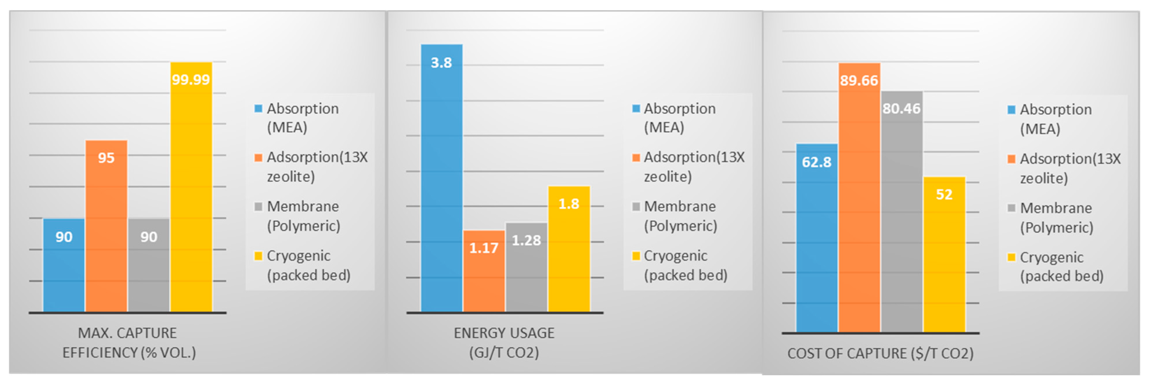
The amount of CO2 recovered from the capture stage depends heavily on the separation technique in the process systems. This paper reviews an overview of CO2 separation technologies, including absorption, adsorption, membrane separation, cryogenic separation, and biological capture. It also presents each technology’s principles, advantages, limitations, and recent advancements. Figure 12 and Figure 13 provide quantitative and qualitative summaries of these separation technologies.
Figure 12. Efficiencies, energy consumption rate, and cost of various separation techniques.
Energies 17 04248 g012

3.2.1. Absorption

Absorption involves the selective capture of CO2 using liquid solvents such as aqueous amines or ammonia-based solutions (such as MEA and 2-amino-2-methyl-1-propanol, which have high absorption ability with about 4.09 mol CO2/Kg solvent, up to 90% CO2 recovery (Figure 12), yielding 99% purity, and a cost of USD 24/t CO2 [40,61]). Other solvents are MDEA, AMP, piperazine, and a mixture of MDEA and MEA [24,66]. CO2 is absorbed into the solvent, forming a solution, which is then regenerated through heating to release the captured CO2. Absorption is a well-established technology widely used in post-combustion capture (chemical absorption–acid-base neutralization reactions) as well as pre-combustion (physical absorption–CO2 solubility in organic solvent and temperature/pressure differential) applications due to its high CO2 removal efficiency [28]. However, it suffers from solvent regeneration’s high energy requirements and potential solvent degradation [67]. Recent research in absorption focuses on developing novel solvents with improved selectivity, stability, and regeneration kinetics. Advanced solvent formulations, including task-specific ionic liquids (ILs) and switchable solvents, show promise in enhancing absorption efficiency and reducing energy consumption (up to 12 mol CO2/kg IL but up to 20% more expensive than conventional solvents) [44]. Process intensification strategies such as membrane contactors and reactive absorption systems are also being explored to improve absorption performance and reduce capital costs [68].

3.2.2. Adsorption

Adsorption (Chemical and physical) involves the capture of CO2 molecules onto solid adsorbent materials with high surface areas and specific surface chemistries [69]. Adsorption technologies offer advantages such as low energy consumption, reversible capture, capacity to capture more than 85% CO2 (Figure 12) with a purity higher than 96%, and potential for integration with renewable energy sources [70]. Various adsorbents, including activated carbon, metal–organic frameworks (MOFs), silica, zeolites (6.18 mol CO2/Kg of zeolite), and porous polymers, have been investigated for CO2 capture applications and make up the physical types [71]. Amine-based sorbents (21.45 mol CO2/kg 70% wt. tetraethylenepentamine (TEPA) and metal oxide (commonly in pre-combustion), as well as alkali-metal-base (7.70 mol CO2/kg adsorbent for 35% wt. Na2CO3/Al2O3) substances, are examples of chemical adsorbents [28]. Recent advancements in adsorption focus on developing next-generation adsorbents with enhanced CO2 adsorption capacities, selectivity, and stabilities. Tailoring the pore structure, surface chemistry, and morphology of adsorbent materials allows for precise control over CO2 capture performance. Additionally, process optimization and integration with pressure swing adsorption (PSA) or temperature swing adsorption (TSA) cycles enable efficient CO2 capture and regeneration [72]. Other ongoing researched adsorbents are MEA-modified activated fly ash, TEPA-modified wood ash, and MIL-101(Cr) monoliths. A study also conducted on various regeneration methods (TSA, VSA, vacuum, and temperature swing adsorption, VTSA, and VPSA) resulted in VPSA being more effective in both productivity and CO2 extraction up to 98% vol followed by VTSA (97% vol) [73,74].

3.2.3. Membrane Separation

Membrane separation involves the selective transport of CO2 molecules across permeable or semi-permeable materials under a concentration gradient or a pressure-driven process [75]. It favors pre-combustion due to reasonably higher CO2 partial pressure and concentration. Membrane technologies offer low energy consumption, compact footprint, and continuous operation. For a single-stage membrane, low separation with low purity (less than 95%) can be achieved. Hence, a multistage membrane process is required [14,76]. Various membrane materials, including polymers, zeolites, and mixed matrix membranes, have been explored for CO2 separation applications [68]. Although inorganic membranes are less expensive and less permeable to CO2, polymeric membranes (polymers of intrinsic microporosity, or PIM) are used in the commercial sector despite their low thermal stability because they are less expensive and more effective in CO2 separations [77]. Recent research on membrane separation focuses on developing high-performance membranes with improved selectivity, permeability, and stability (mixed-matrix-membranes (MMMs), facilitated transport membranes (FTMs, in pilot phase with 1.02 GJ/t CO2 energy usage and costs USD 47.87 per ton CO2 capture) and gas–liquid membrane contactors, which does not require pressurization of flue gas and, hence, reduces energy usage [78]. Advanced membrane fabrication techniques, such as interfacial polymerization, electrospinning, and layer-by-layer assembly, enable precise membrane properties, and morphology control. Additionally, membrane module design optimization and process intensification strategies enhance CO2 separation efficiency and reduce operating costs [79].

3.2.4. Cryogenic Separation

Cryogenic separation involves the condensation and liquefaction (staged of compression and cooling) of CO2 at low temperatures (−100 to −135 °C) and high pressures (101 to 203 bar), followed by phase separation to recover high-purity CO2 of about 99.99% by volume (Figure 12) [80], and it is highly applicable to pre-combustion and oxy-fuel combustion techniques [81]. Cryogenic technologies offer advantages such as high CO2 recovery efficiency, scalability, and reliability. However, they suffer from high energy consumption and capital costs associated with refrigeration equipment and compression systems [28]. Advancements in cryogenic separation focus on improving process efficiency and reducing energy consumption through innovative process configurations and cryogen selection. Advanced refrigeration cycles, such as mixed refrigerant cycles and cascade refrigeration systems, enable efficient CO2 separation at lower temperatures and pressures [28]. Other developed types of cryogenic systems are packed-bed (a cost-effective with USD 126.50/t CO2 avoidance as compared to USD 54.50, and USD 120 for amine-scrubbing and membrane, respectively), external-cooling loop (energy usage of 0.74 Gt/CO2 when CF4 is used and achieves CO2 purity of 99.2% by volume), anti-sublimation (1.25 Gt/CO2 energy usage, that is 21% lower than MEA capture and a 90% capture rate), distillation (99.9% purity, 0.43 Gt/CO2 and USD 10.28/t CO2 cost of capture), controlled-freeze zone (can recover up to 100% CO2), CryoCell (81% more energy efficient and 33% less on capture cost but lower recovery), and Stirling cooler systems (CO2 capture of about 85% vol with 3.4 Gt/CO2) [28]. Process integration with renewable energy sources and waste heat recovery systems enhances overall energy efficiency and sustainability [82].

3.2.5. Biological Separation

Biological capture involves harnessing the natural CO2 sequestration capabilities of photosynthetic organisms such as algae, bacteria, and plants (CO2 capture potential is about 1 to 10 tons per hectare, and also estimated that reforestation can reduce global CO2 by 3.6 Gt/yr. by mid-century) [83]. Biological CO2 capture technologies offer advantages such as renewable feedstocks, carbon-negative processes, and potential co-production of biofuels or bioproducts. Ref. [84] found that a cyanobacterium, which can grow at a rate of 0.04/hectare, can remove about 109.2 mg/L/hectare by volume of CO2. Various bioreactor configurations, cultivation strategies, and genetic engineering approaches have been explored to enhance CO2 capture efficiency and productivity [85].
Recent research on biological capture focuses on optimizing cultivation conditions, improving CO2 fixation pathways, and enhancing biomass productivity. Engineered microalgae strains with enhanced CO2 uptake rates and lipid accumulation capacities show promise in bioenergy and bioremediation applications [86]. Additionally, integration with wastewater treatment processes and nutrient recycling systems enhances resource efficiency and economic viability [87].

3.3. Transportation of Captured CO2

Captured CO2 undergoes compression (pipeline transport) (at pressures above 74 bar and temperature 31 °C into a supercritical phase) to reduce its volume and increase its density, or refrigeration (ship, truck, or rail transport) and dehydration (to remove water, preventing corrosion due to formation acidic solutions), making it effortless and cheaper to transport over long distances [28,35]. Currently, transporting CO2 through pipelines is the most common approach (Figure 14). CO2 pipelines, similar to natural gas pipelines, are specifically designed (usually, 86–152 bar and 13–43 °C pressure and temperature, respectively [88]) to handle CO2 and can transport large volumes (50 Mt of CO2 per year) of CO2 over considerable distances (over 2500 km and 2.2 km by land and sea, respectively), connecting capture sites with storage or utilization sites (IEA, 2020) [89]. The cost of transport may vary considerably based on factors such as the amount of CO2 (pipeline capacity rating), distance, transportation mode (sea or land), economic indices, and region or country. According to [38], the United States Gulf Coast carbon capture and storage in the year 2020 over a distance of 180 km (for 20 Mt per year) and 300 km (1 Mt per year) was estimated to cost USD 2.41 and USD 24.48 per ton of CO2 transported, respectively. Also, for a distance of 180 km offshore in Northern Europe, and for 2.5 Mt of CO2 per year, USD 10.69 per ton was estimated as compared to USD 6.21 per ton when transported on land [28]. GCCSI [90] shows that a large-scale CCS network is one laudable approach to reducing the significant pipeline transport costs (Figure 15). In cases where pipeline infrastructure is not available, CO2 may be transported via ships or tankers (this is a mature industry with over thirty years of deployment, and also over eighty years of commercial shipments of LNG and LPG could be adopted), especially for oceanic transport or to remote areas. CO2 shipping involves storing the CO2 in specialized containers or tanks onboard ships (on average, a tanker at conditions of 17 bar and −40 °C has the capacity to carry about forty-five Kilo tonnes of liquefied CO2, and transporting it to its destination port (IEA, 2020) [28,38]. Estimated shipping cost by [90] is summarized in Figure 15. Trucking is another method for CO2 transportation, particularly for shorter distances (less than 322 km when trucks are used and less than 1609 km when rail is used for volumes from four tonnes [91]) or areas without pipeline infrastructure. CO2 is loaded into trucks or tankers and transported to nearby storage or utilization sites [92]. Throughout the transportation process, stringent monitoring and safety measures (Figure 14) are implemented to ensure the safe handling and transport of CO2. This includes monitoring CO2 flow rates, pressure, and concentration, as well as implementing leak detection systems and emergency response protocols to prevent and mitigate potential incidents [2].
Figure 13. Comparative summary of various separation technologies [45,67,93,94,95].
Energies 17 04248 g013
Figure 14. Comparative summary of various transport modes [45,83,92,96].
Energies 17 04248 g014
Figure 15. Estimated cost of transport for onshore and offshore [90].
Energies 17 04248 g015

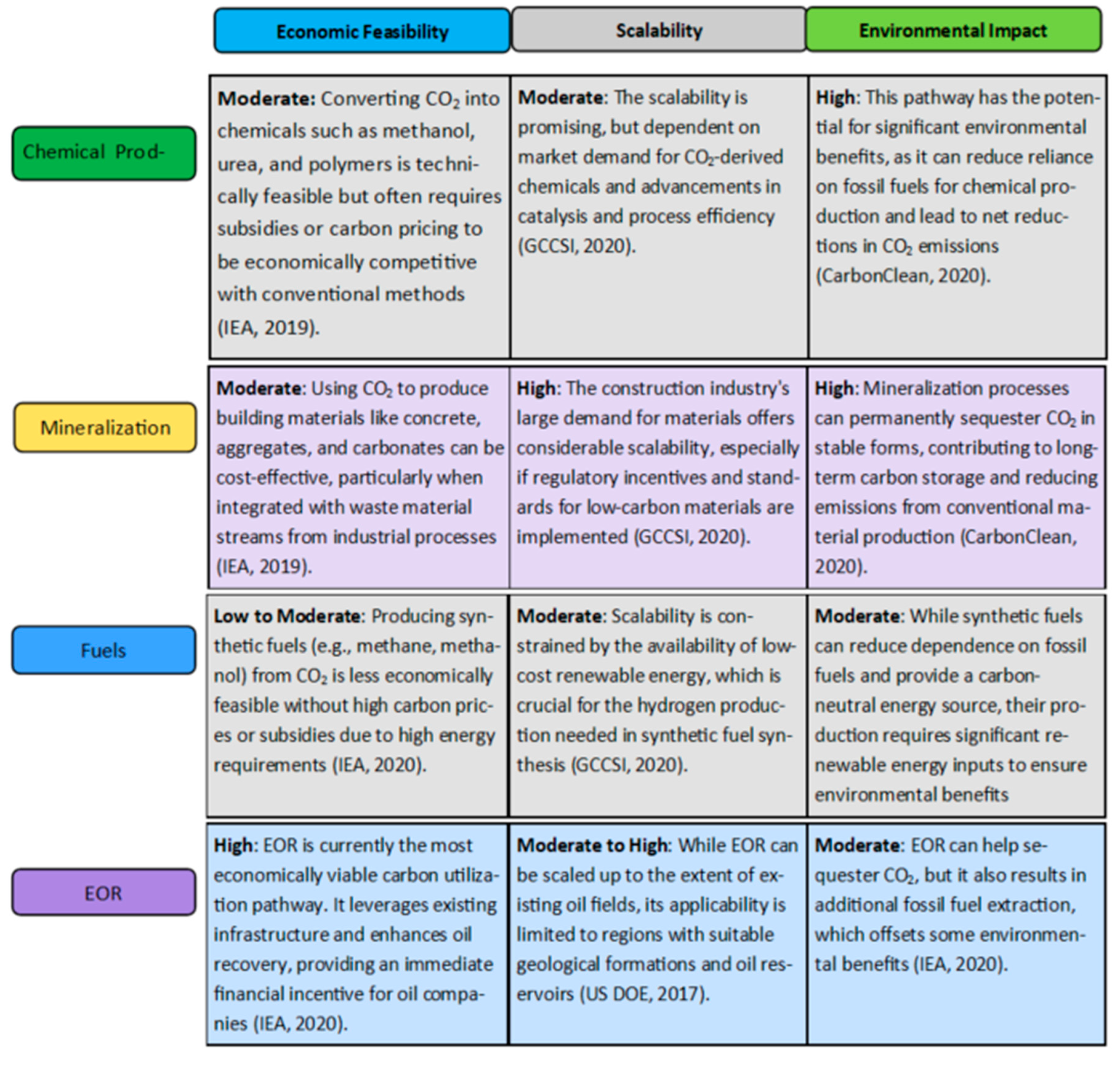
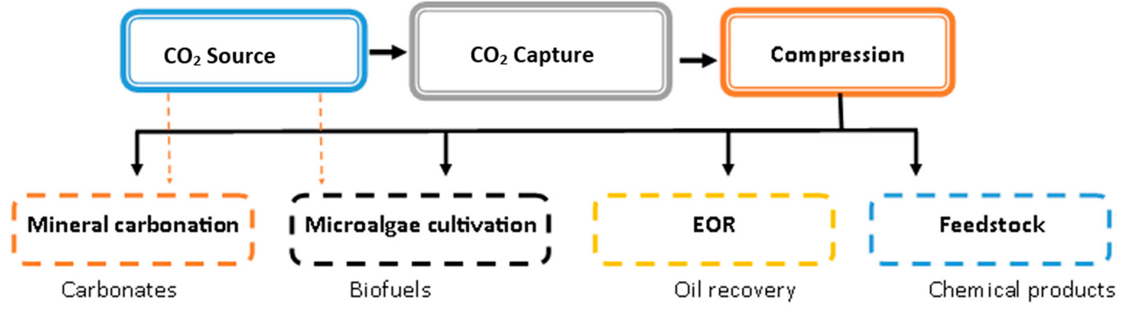
3.4. Carbon Capture and Utilization (CCU) Pathways

Captured CO2 can be utilized to generate valuable products, effectively transforming GHG into a resource [97]. Ref. [98] estimated and predicted annual global usage to be 150 MtCO2, 230 Mt, 250 Mt, and 272 Mt of CO2 for 2000, 2015, 2020, and 2025, respectively. Pathways to CCU include direct use of CO2 (non-conversion), chemical conversion, biological conversion, mineralization, and enhanced oil and gas recovery (since the 1970s). Figure 16 shows the average annual CO2 utilization per sector. Urea production with a yield of one tonne (costing USD 245/tonne urea) per 0.774 tonne CO2 utilized (average) (fertilizer industry, through the reaction between CO2 and NH3 at conditions of high temperature–high pressure (HTHP)) and oil and gas production (EOR) as the major utilization pathways for CO2, accounting for 57% and 34%, respectively [90,98,99].
Chemical pathways typically involve the catalytic conversion of CO2 into fuels (diesel, aviation fuel, and gasoline) and chemicals. This includes the synthesis of methanol, dimethyl ether, and hydrocarbons (catalytic hydrogenation of CO2 using renewable hydrogen for environmental viability) through processes such as Fischer–Tropsch synthesis [24,98] with about seventy demonstration plants in Europe. For example, the Sabatier process converts CO2 and hydrogen into methane and water, providing a potential route for synthetic natural gas production (with 94% CO2 utilization for about 1.4 t CO2 per tonne methanol produced and 0.61 GJ/t methanol energy) [100,101]. However, these fuels are not highly competitive compared to petroleum and other energy sources due to intensive capital requirements and low efficiency in energy conversion. Polymers (15 Mt/year from 1.5 Mt of CO2 was estimated in 2016) from olefins (conversion of methanol) have a variety of applications, ranging from the health and food industry to technology [98].
Biological pathways utilize the natural metabolic processes of organisms to convert CO2 into organic compounds. Algae cultivation is a prominent example (on average 1.8 t CO2/1 tonne dry algae production), where microalgae fix CO2 during photosynthesis and produce lipids that can be converted into biofuels [97]. Cyanobacteria are also being explored for their ability to produce biofuels and bioplastics from CO2. Though there is a high potential for CO2 utilization through biological pathways, cultivation systems are capital intensive, like the agricultural sector, for large-scale algae production [90]. Pure CO2 can also be used to boost the yield of crops cultivated in greenhouses by an average of thirty percent increase in crop yield (0.55 Kg CO2/h/100 m2 average requirement) [98,99,102].
Mineralization involves the reaction of CO2 with metal oxides or alkaline brine (CaO, MgO) to form carbonates (e.g., CaCO3 and MgCO3). This process can be used for permanent CO2 sequestration and for producing construction materials (0.5 t CO2/1 t carbonate or 1.6 Gt CO2/year can be reduced [90,103]). One example is the reaction of CO2 with magnesium silicate to form magnesium carbonate, which can be used in building materials [104,105]. Separation and compression of CO2 are eliminated from mineralization into carbonates, thus reducing the energy requirement for this process, which is one of its advantages. Steam and autoclave curing processes in concrete have high energy requirements. CO2 curing (injection of CO2 into the concrete mixture to reduce the steam and heat in precast-concrete products), a much better approach, can utilize less than 120 kg of CO2 to yield about a tonne of concrete, and this can result in about 96 kt utilized to produce 800 kt of precast concrete annually, as published by [99].
Though CCU presents a path to carbon reduction, a detailed techno-economic life cycle assessment is required to comprehend the complexities inherent in its operations and market dynamics. However, according to Refs. [98,106], CCU only complements CCS and is not an approach for large-scale CO2 reduction. Figure 17 summarizes various CCU pathways and assessments based on economic feasibility, scalability, and environmental impact. Overall, the selection of carbon utilization pathways should consider a balanced approach, leveraging each method’s economic and environmental strengths, to contribute to broader climate goals.

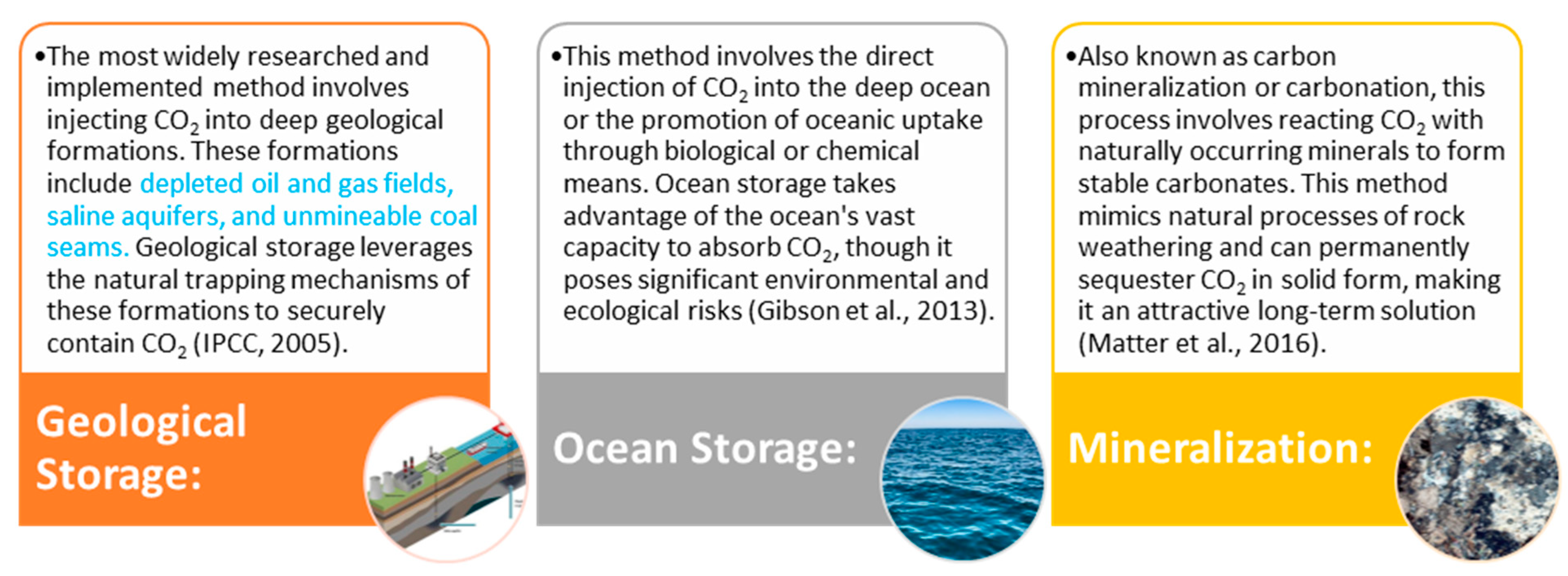
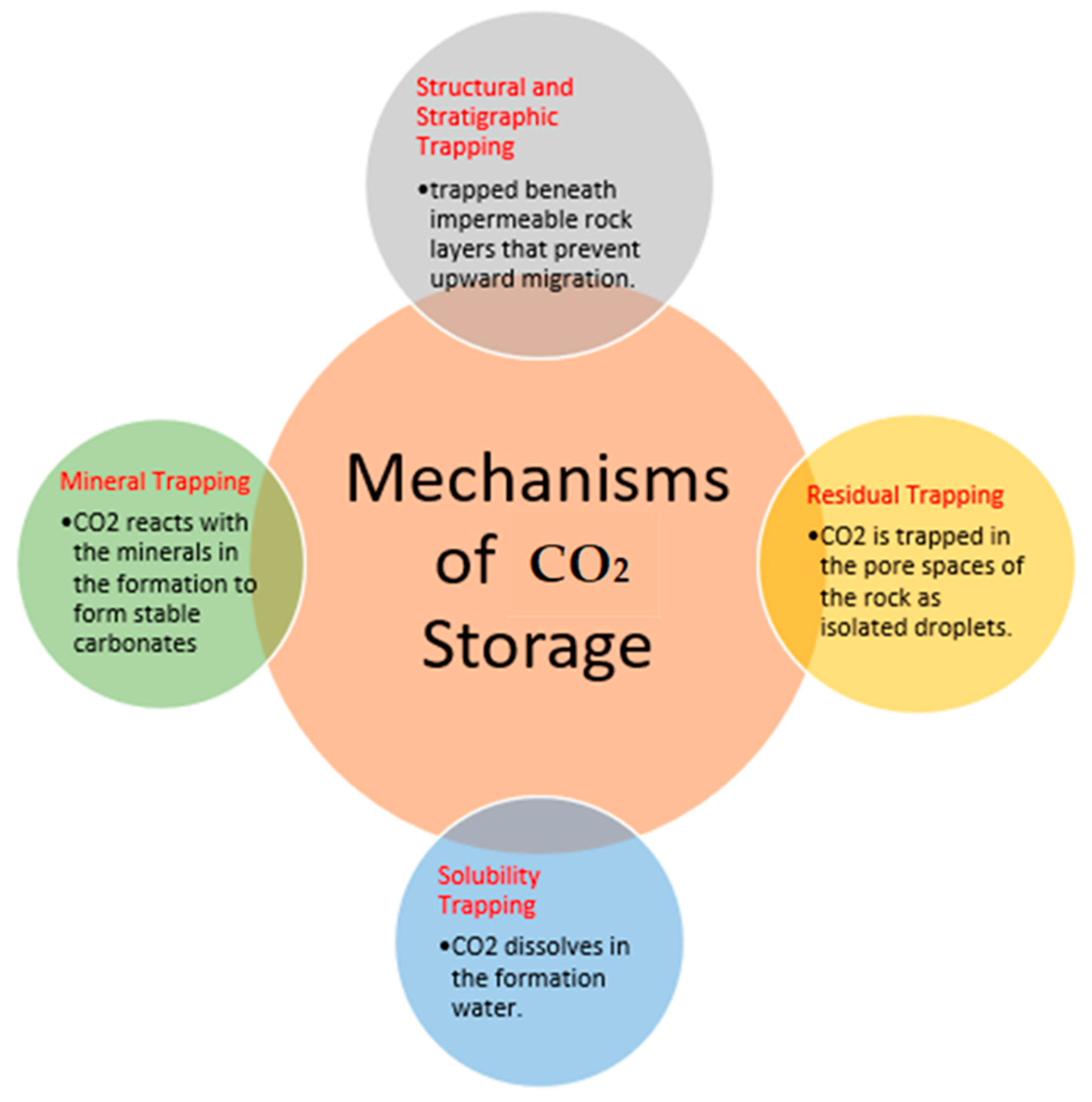
4. Carbon Storage Technologies (CCS Pathways)

Carbon storage (CCS) is one of the most effective, efficient, and critical pathways to achieving CCUS mandates [26]. These technologies aim to sequester captured carbon dioxide (CO2) (compressed to pressures above 1088 psi to supercritical or liquified form) in favorable geological formations (depths beyond 2624.67 ft and good storage, flow capacity, and a confining cap-rock with good sealing integrity) to prevent its release into the atmosphere, thus mitigating the greenhouse effect and global warming [106]. Figure 18 presents an overview of various carbon storage methods, including geological, ocean storage, and mineralization. Ref. [38] publish economic figures of injection and storage projects for the United States Gulf Coast onshore and offshore to be USD 1.72 and USD 18.97 per tonne of CO2, respectively, for 2020 terms and an average of USD 2.93 per tonne for monitoring and verification. Table 1 and Table 2 summarize the features and factors for consideration in selecting various storage resources.

4.1. Geological Storage

4.1.1. CO2—EOR with Storage

A significant quantity (about two-thirds) of unproduced hydrocarbons in reservoirs is due to a decline in primary recovery in the conventional crude oil recovery approach [108]. This has led to the research and development of other residual oil extraction techniques before a field is abandoned [109]. Injection of gas, which is one of the non-thermal EOR techniques and has gained widespread popularity (accounting for over 50% of EOR applications in the USA), employs the injection of gases such as produced natural gas, or enriched natural gas, carbon dioxide (CO2), Nitrogen gas (N2), and flue gas (gas with over 70% of N2 as a compositional component) into crude oil reservoirs [110]. This increased application of this technique is due to the high effectiveness of the mechanism involved in using these gases for oil recovery [110,111]. Through miscibility or immiscibility, gas diffuses into crude oil when injected into it. This causes the oil to swell, leading to a reduced oil viscosity. This enhances the mobilization of trapped oil (due to capillary forces), mostly in pore spaces, where the injected gas reaches miscibility with the crude oil by exchanging components. Gas EOR is partly influenced by reservoir temperature and pressure and the composition/properties of both crude oil and injecting gas [109]. There are two ways by which miscibility can be achieved: contact miscibility (FCM) and Multi-contact miscibility (MCM). FCM occurs when reservoir oil and injected gas form a single-phase fluid upon initial contact at any ratio. While with MCM, no FCM occurs, but the injected and reservoir oil achieve miscibility through a continuous mass transfer through phases, which occurs in three displacement procedures: vaporizing gas drive, condensing gas drive, and the two combined [112].
There have been several gas injection EOR projects with variable gas choices depending on their ability to enhance recovery. CO2, as stated by [113], has had a comprehensive implementation (over 50 years) globally due to its extraction power and dissolution rate. CO2 is noted to achieve miscibility at low pressures and gas override is eliminated due to its density [109]. In other studies, enriched CO2 with intermediate hydrocarbon components and flue gas has been reported to reduce the minimum miscibility pressure (MMP), (a significant parameter in determining miscibility). MMP is the minimum pressure beyond which an injected gas and oil would achieve a miscible displacement. This is a key criterion in the selection of gas for EOR [109,113,114]. As reported by [109,115], Nitrogen gas (the most abundant, least expensive, and an inert gas, and hence introduces no impurities into oil [110]) has seen wide usage in the oil gas industry for gas lifts, maintaining reservoir pressure, and recycling of gas as an alternative mainly due to inherent challenges with the use of CO2 and natural gas: cost and availability, as well as issues regarding corrosion and environmental constraints. However, recent advocacy and governmental policies on combating global warming, and hence making provisions for incentives on the storage of anthropogenic CO2 through EOR operations, have awoken massive interest and investments into the usage of CO2. In this instance, the produced CO2 with crude oil is separated and recycled, and further injected until it is securely sequestered at the end life of the reservoir [3,30]. Hepburn, 2019 [97] reported an average EOR CO2 utilization estimate by the year 2050 to be 0.95 gigatons, while global estimates report an average of 4.7 × 10¹¹ barrels of enhanced oil recovery by injecting 110 gigatons and a maximum of 140 gigatons of CO2. While CCS may be capital intensive, a cut of about USD 40 and USD 15 per Mega watthour can be attained for power plants (coal and natural gas, respectively) retrofitted with CCS with EOR option if a tax incentive of about USD 40 per ton of CO2 is utilized. The high capital cost associated with CCS makes storage through CO2-EOR cost-effective as compared to other storage options. The authors in [116] estimated that for an average cost of CO2 in the range of USD 45 to USD 60 per ton at USD 100 per barrel of crude oil, CO2-EOR will be economically viable.
CO2 also presents favorable properties enabling it to be utilized in fracturing activities. Liquid or supercritical CO2 is injected at high pressures to initiate fractures in reservoir rocks, typically in unconventional formations such as shale, with low permeability [117]. Compared to water, CO2 has a low viscosity, enabling easy penetration in micro-fractures to improve oil and gas recovery. CO2 causes no formation damage and is favorable for formations with sensitive clays, which may swell in the presence of incompatible fluids such as water [118].

4.1.2. CCS in Depleted Oil and Gas Reservoirs (DOGR)

DOGR (with 675 gigatons to 900 gigatons CO2 estimated global storage capacity) has become a prominent and feasible option for geologically storing carbon dioxide (CO2). These reservoirs, which have already been extensively mapped and characterized, offer significant advantages for CO2 storage. These include existing infrastructure and proven containment capabilities [119]. The storage potential of these reservoirs can be explained by various mechanisms, including structural and stratigraphic trapping, residual trapping, solubility trapping, and mineral trapping (Figure 19). DOGRs are usually identified by a cap rock, an impermeable layer that originally trapped hydrocarbons. This geological feature can effectively trap CO2, preventing its migration to the surface [120]. The structural integrity of these formations ensures that CO2 can be stored securely over long periods. During CO2 injection, some of the CO2 becomes trapped in the micro-pore spaces of the reservoir, through capillary forces. This residual trapping occurs when the CO2 is immobilized in the tiny pores of the reservoir rock, significantly reducing the risk of leakage [121]. Injected CO2 can dissolve in the formation water (brine) in the reservoir. This solubility trapping increases the density of the CO2–brine mixture, reducing the buoyancy of CO2 and enhancing its stability within the reservoir [9]. Over extended periods, CO2 can react with the minerals in the reservoir rock to form stable carbonate minerals. This process, known as mineral trapping, provides a permanent storage solution as the CO2 is converted into solid minerals [122]. The average storage cost in Europe was estimated to be USD 3.18/t CO2 (onshore) and USD 7.64/t CO2 (offshore) at an average depth of 2 km, as reported by [123] in 2004. The Permian basin in Texas, USA, estimates USD 3.81/t CO2 and USD 4.86/t CO2 at about 1.6 km for depleted oil and gas fields, respectively [124]. Though DOGRs provide significant storage potentials, their injectivity and capacity can vary. Hence, a detailed geological assessment is required to select suitable reservoirs [121].

4.1.3. Saline Aquifers

Saline aquifers (a mature storage technique) represent a vast and underutilized potential for CO2 storage, offering immense capacity (1000 Gt to 10,000 Gt) and widespread availability. These formations consist of brine-saturated porous rock, typically found at great depths below freshwater aquifers [28]. Structural and stratigraphic trapping, residual trapping, solubility trapping, and mineral trapping (Figure 19) also describe the trapping mechanisms present in saline formations. Hendriks et al., 2004 [124], estimated the onshore and offshore average cost for a storage depth of 2 km in Europe to be USD 2.43–7.97 tCO2 and USD 6.06–15.41 tCO2, respectively. For a storage depth of 1.2 km in USA Bock et al., 2003 [124], estimated USD 2.97 tCO2. Suitable saline aquifers are typically found at depths greater than 800 m, where the pressure and temperature conditions ensure that CO2 remains in a supercritical state. Supercritical CO2 has a higher density and lower viscosity than its gaseous form, facilitating efficient injection and storage [125]. The porosity (storage) and permeability (flow capacity) of the reservoir rock determine its capacity to store CO2 and the ease with which CO2 can be injected. High porosity and permeability are desirable as they enable the storage of larger volumes of CO2 and reduce the injection pressure required [126]. The chemical composition of the formation water influences CO2 solubility and the potential for mineral trapping. Saline aquifers with favorable geochemical conditions promote enhanced dissolution and mineralization of CO2, contributing to long-term storage security [9]. Injecting CO2 into a saline aquifer increases the reservoir pressure, which must be carefully managed to avoid fracturing the cap rock or inducing seismic activity. Pressure relief mechanisms, such as the extraction of formation water, may be employed to maintain safe pressure levels [127].
The risk of CO2 leakage through faults, fractures, or abandoned wells is a significant concern. Comprehensive site characterization, robust monitoring systems (time-lapse (4D) seismic surveys provide dynamic images of CO2 plume migration and reservoir behavior over time), and contingency plans are essential to detect and mitigate potential leaks [26]. The injection of CO2 into saline aquifers can alter the geochemical equilibrium, potentially impacting groundwater quality and ecosystem health. Careful monitoring of the chemical composition of the formation of water and surrounding environments is necessary to prevent adverse effects [128].

4.1.4. CO2-Enhanced Coalbed Methane (ECBM)

This constitutes a dual-purpose technology with the injection of CO2 into partially depleted coal seams to recover methane gas and has gained significant attention recently [129,130] (1,2). The affinity of CO2 to adsorbed coal leads to the displacement of CH4, allowing for improved extraction of CH4 [131]. Because of this, ECBM offers the benefit of increased methane production (70% more) [132], CO2 storage in coal seams (about 3 Gt−200 Gt storage capacity), and improved coal resource utilization [130,133]. The storage ratio (CO2 adsorbed to coal bed methane adsorbed) can range from 2:1 to 13:1 for ultra-high-quality coal to low-quality coal [90]. The high cost of CO2, the absence of reliable CO2 sources in some regions, technical and geological constraints, and potential environmental impacts (alteration in groundwater chemistry and seismicity) are some challenges facing the implementation of ECBM [132,134,135]. Also, coal’s pasteurization and swelling (geomechanical effect) will reduce coal permeability and close fracture connections networks. Infill wells and hydraulic fracturing (increased permeability) will, therefore, be required, and an extra increment in the capital (an estimate of 270 wells is required for 2.2 Mt/yr. at USD 5.45/t CO2 in the USA [38]. Given these, future studies are focused on optimizing CO2 injection strategies (effect of pressure, temperature, and CO2 concentration), development of new ECBM techniques (the use of flue gas and N2-ECBM for cost reduction), and CO2 storage capacity enhancement [129,130]. The pulsed injection and the use of foamed CO2 are reported to have shown an improved efficiency of ECBM processes by enhancing the distribution of CO2 in coal seams and minimizing potential leakage pathways [136].

4.2. CO2 Mineralization

Also known as mineral carbonation, CO2 mineralization occurs when a stable carbonate mineral is formed through the reaction between CO2 and naturally occurring minerals (metal oxides, typically in silicates and carbonate minerals) (Equations (1) and (2)), mimicking natural geological processes offering a permanent CO2 sequestration. Three stages characterize this: CO2 dissolution (forming HCO3− and CO32−), mineral dissolution (reaction of carbonic acid with the mineral leading to the dissolution of metal cations like Mg2+ and Ca2+), and carbonate precipitation (reaction of metal cations with CO32−) as MgCO3 or CaCO3. Mineralization can occur in situ, where CO2 directly injected into rocks such as basalt or ultramafic rocks leverages the natural geological setting to form carbonates [137]. Or ex Situ, where reactive minerals are extracted, crushed, and reacted with CO2 in a controlled process that requires significant energy and material handling for optimization [138]. Current research is geared toward the optimization of reaction rates (grinding using catalysts and pressure, temperature optimization) [139], exploration of the use of industrial by-products (fly ash and steel slag) due to their high metal oxide content for mineral carbonation [105], and studies on the integration of CO2 mineralization with industrial processes such as flue gas treatment and desalination [140]. About 90% of the mineralization rate can be achieved with a global estimated storage capacity of 6 × 10⁷ (the Ocean basin has enormous basalt reserves, onshore typically vast reserves in Washington, Russia, and India) [13]. There are two pilot projects, namely, the Wallula and CarbFix projects, in the USA and Iceland, respectively.
CO2 + Metal Oxide → Carbonate Mineral
For instance, the reaction with olivine (Mg2SiO4) can be represented as:
Mg2SiO4 + 2CO2→2MgCO3 + SiO2

4.3. Oceanic Storage

The ocean has a vast CO2 absorption capacity (about 38,000 Gt), offering it great potential for mitigating atmospheric CO2 levels (with annual storage of 1.7 Gt) [69]. CO2 is injected or pumped directly into the deep ocean at over 1000 m. Due to the high pressure and low temperature, CO2 forms dense liquids or hydrates (less buoyant and more stable), which makes it less likely to escape back into the atmosphere [128]. CO2 injected into the ocean can dissolve or diffuse into seawater to form carbonic acid (H2CO3), which dissociates to form HCO3- and CO32− ions. These are ions already in seawater composition and a part of the ocean’s carbonate buffering system for pH balance [140]. Techniques such as pipelines and tankers used in transporting CO2 offshore injection sites and the development of nozzles and diffusers to enhance dissolution rates have received great attention to maximize CO2 retention and minimize environmental impacts [128]. Other techniques involve improvement in absorption capacity by (enhanced weathering) the addition of alkaline substances (e.g., pulverized silicate rocks) to the ocean. In this process, the natural weathering reactions that remove CO2 from the atmosphere are accelerated and stored as HCO3− [140]. Another approach to enhance the biological uptake of CO2 is (Ocean fertilization) by adding nutrients such as iron to stimulate phytoplankton growth. This enhances a biological pump that transfers more CO2 from the surface to the deep ocean as organic matter sinks [141]. Aside from the vast storage capacity, ocean acidification and ecological disruption are major concerns with CO2 storage. Direct injection and the resulting CO2 plume create localized zones of high CO2 concentration, potentially harming deep-sea ecosystems. Organisms in these zones may experience hypercapnia (elevated CO2 levels in body fluids), leading to physiological stress and mortality [128]. The long-term stability of stored CO2 is a critical concern. Factors such as ocean currents, temperature gradients, and potential hydrate dissociation must be carefully monitored to ensure that stored CO2 does not return to the atmosphere over time (House et al., 2006) [142].
Table 1. Key parametric assessment considerations of storage media for CO2 [9,92,125,126,127,128,143,144].
ParameterStorage Medium
GeologicalOceanicMineralization
Storage CapacityHigh capacity, particularly in deep saline aquifers, but site-specific.Very high capacity due to the vast volume of the ocean.Limited by the availability of reactive minerals but offers permanent storage.
Stability and
Performance
Generally stable, but risks of leakage and induced seismicity.Long-term stability is uncertain, and there is potential for acidification and ecological impacts.Permanent and stable, forming solid carbonates.
Monitoring and
Verification
Requires extensive and continuous monitoring.Difficult to monitor, especially for deep-sea injections.Minimal monitoring is needed post-reaction.
Environmental
Impact
Potential for groundwater contamination and induced seismicity.Ocean acidification, ecological disruptions.Mining and processing impacts but stable final products.
Economic
Consideration
High initial costs, potential revenue from EOR.High costs for infrastructure and monitoringHigh energy and material costs, the potential for utilization of industrial waste.
Table 2. Summary of storage mechanisms [9,92,125,126,127,128,143,144].
TypesMechanismAdvantageChallenge
GeologicalDepleted Oil/gasUtilizes existing reservoirs that have held hydrocarbons for millions of years, providing a proven trap for CO2.Well-understood geology, existing infrastructure, and potential for enhanced oil recovery (EOR).Limited capacity, and potential for CO2 leakage through old wells, require detailed site characterization.
Deep SalineInjects CO2 into porous rock formations saturated with saline water.Vast storage potential, and widespread availability.Requires extensive monitoring, potential for induced seismicity, less characterized compared to oil and gas reservoirs.
Unmineable CoalCO2 adsorbs onto the surface of coal, displacing methane.Potential for enhanced coalbed methane recovery (ECBM).Limited storage capacity, complex adsorption dynamics, potential for CO2 leakage.
OceanicDirect InjectionCO2 is injected into the deep ocean where it forms a dense liquid or hydrates.High potential storage capacity, and long-term sequestration potential.Ocean acidification, ecological disruptions, and uncertain long-term stability
Enhance WeatheringAdding alkaline minerals to the ocean to increase CO2 uptake.Natural process acceleration, potential co-benefits for ocean chemistry.Large-scale feasibility, and environmental impact of mineral extraction and distribution
Ocean fertilizationAdding nutrients to stimulate phytoplankton growth, enhancing biological carbon pump.Can sequester CO2 in organic matter, relatively low-cost.Ecological risks, limited and variable efficacy, and potential for negative feedback
MineralizationIn SituCO2 is injected into subsurface rock formations, such as basalt, where it reacts with minerals to form carbonates.Permanent storage, natural process, minimal monitoring post-injection.Slow reaction rates, limited suitable sites, and energy-intensive
Ex SituReactive minerals are mined, crushed, and reacted with CO2 in an industrial setting.Controlled conditions, and use of industrial by-products.High energy and resource requirements, environmental impact of mining and processing

5. Policy and Regulatory Framework

The role of comprehensive policy frameworks in advancing CCUS technologies is paramount to achieving global climate goals. Policies provide the regulatory environment, financial incentives, and institutional support to drive CCUS deployment. Harmonizing national and international policies ensures consistency and facilitates the scaling of CCUS technologies across borders, making global cooperation vital.

5.1. National and International Policies

The US leads in CCUS development. The US amended its Clean Air Act to include provisions for reducing greenhouse gas (GHG) emissions, which set the stage for CCUS regulations. The act mandated the Environmental Protection Agency (EPA) to regulate CO2 emissions from power generation plants and industrial sources. The 45Q tax credit (2018) and the Infrastructure Investment and Jobs Act (2021) provide significant financial incentives for CO2 capture and storage, demonstrating robust federal support [14,145]. State-level policies, such as California’s Low Carbon Fuel Standard (LCFS), complement federal initiatives by providing additional incentives for low-carbon technologies, including CCUS [146]. The European Union Green Deal aims to make Europe climate-neutral by 2050. CCUS is identified as a key technology for decarbonizing hard-to-abate sectors. The EU has also integrated CCUS into its strategic plans and funding mechanisms [147]. The EU integrates CCUS into its climate strategy. The EU Emissions Trading System exempts captured CO2 from emission allowances, and the Innovation Fund supports large-scale CCUS projects. However, deployment faces public opposition and regulatory challenges [147,148]. China’s climate goals include CCUS, with the 14th Five-Year Plan (2021–2025) targeting carbon neutrality by 2060 through provisions for CCUS research, pilot projects (e.g., the Yanchang integrated CCUS project), and integration into national GHG reduction strategies [149]. Investments focus on CO2 utilization in enhanced oil recovery, but deployment is limited and inconsistent at the provincial level [150]. Australia’s CCUS policies support its fossil fuel industry through the Carbon Capture, Use, and Storage Development Fund and the Safeguard Mechanism. However, reliance on CCUS is criticized for its feasibility and cost compared to renewable energy [151].
Internationally, The Paris Agreement (2015) supports CCUS for balancing emissions and removals by the century’s second half [152]. The IEA advocates for CCUS, outlining its necessity for net-zero targets by 2050 and promoting global collaboration (IEA, 2020; 2021) [26]. The UNFCCC supports CCUS through the Clean Development Mechanism and the Green Climate Fund, despite debates over its viability [152,153]. The effectiveness of CCUS policies varies. In the U.S., incentives like the 45Q tax credit have spurred private investment and numerous projects [145]. In contrast, the EU’s strict regulations have slowed deployment despite significant funding [154]. High costs and uncertainties in long-term storage impede large-scale CCUS adoption. The limited market for CO2 utilization reduces economic incentives beyond enhanced oil recovery (EOR) [14,41]. Public opposition and regulatory barriers hinder CCUS implementation, especially concerning CO2 storage. Consistent regulatory frameworks are needed to address safety concerns and streamline approvals [147,154]. CCUS’s role in climate mitigation is debated. Critics argue it diverts resources from more cost-effective renewable energy solutions, while proponents highlight its necessity for hard-to-abate sectors like cement and steel production [26,151].
The 28th session of the Conference of the Parties (COP28) to the UNFCCC, held in Dubai from 30 November to 12 December 2023, gathered representatives from nearly 150 countries [155,156]. A key objective was the first-ever Global Stock Take (GST), comprehensively assessing collective progress toward the Paris Agreement goals [155,156]. Key objectives of COP28 included enhancing adaptation strategies, addressing climate finance needs for developing countries with a USD 100 billion per year goal, operationalizing the Loss and Damage mechanism established at COP27, and finalizing rules for international carbon markets under Article 6 [155,156]. Technical discussions focused on renewable energy deployment, particularly green hydrogen, solar, and wind energy; energy efficiency with smart grids and energy management systems; nature-based solutions like reforestation and wetland conservation; technological innovations including carbon capture and storage (CCUS), advanced nuclear energy, and sustainable aviation fuels; and climate resilience through resilient urban planning and climate-proofing supply chains [156]. Expected outcomes included more ambitious NDCs, new financial commitments for loss and damage, totaling about USD 792 million, and additional pledges to the Green Climate Fund amounting to USD 12.8 billion and over 85.1 billion committed so in total for all aspects [156]. The conference also aimed to enhance international cooperation and update policy frameworks [155,156]. Stakeholders from the private sector, civil society, and the scientific community actively participated [155,156]. Challenges highlighted included ensuring equity and fairness, maintaining accountability in implementation, and navigating geopolitical tensions. COP28 aims to be a pivotal milestone in accelerating climate action and enhancing international cooperation [155].

5.2. Incentive and Funding Mechanisms

Financial incentives and funding mechanisms are crucial for the advancement of CCUS technologies. They mitigate the high costs and investment risks associated with CCUS projects, encouraging private and public sector participation. The U.S. promotes CCUS through incentives like the 45Q tax credit, established in 2018, offering financial rewards for CO2 capture and storage, with higher credits for geological storage (USD 50 per metric ton) than for enhanced oil recovery (USD 35 per metric ton) [145]. The Department of Energy (DOE) funds CCUS via programs like the Carbon Capture Program and CarbonSAFE, supporting research and large-scale projects [14]. The EU backs CCUS through the Innovation Fund, financed by the EU Emissions Trading System (ETS), which grants funds for large-scale CCUS projects (European Commission, 2020) [138]. The EU ETS also indirectly encourages CCUS by pricing carbon emissions. Additionally, member states like the UK support CCUS with initiatives such as the CCS Infrastructure Fund (CIF), promoting shared CO2 transport and storage facilities [157]. China’s 14th Five-Year Plan (2021–2025) integrates CCUS to achieve carbon neutrality by 2060. The government provides funding and tax incentives for CCUS projects, with additional support from provincial governments, though it varies by region [158]. Australia promotes CCUS through the Carbon Capture, Use, and Storage Development Fund, offering grants to mitigate technical and commercial risks (Australian Government, 2021) [159]. The Emissions Reduction Fund (ERF) includes a Safeguard Mechanism, allowing emitters to use CCUS to meet emission reduction targets, incentivizing adoption [153].
Private sector funding, such as Venture capital investments, has driven innovation in CCUS by funding startups developing cutting-edge technologies. Private equity funds focused on clean energy have also allocated resources to CCUS projects, promoting large-scale implementation [160]. Public–private partnerships (PPP) like The Petra Nova project in the US, a successful PPP, integrated CCUS with EOR, demonstrating the viability of such collaborations. PPP frameworks often include agreements on cost-sharing, risk management, and joint project management, which facilitate large-scale CCUS deployment [92]. The IEA promotes global CCUS deployment through reports and roadmaps, advocating for policies, financial incentives, and international collaboration to share knowledge and reduce costs (IEA, 2020) [26]. The Green Climate Fund (GCF), under the UNFCCC, supports CCUS projects in developing countries by providing financial resources for emissions reduction and sustainable development. However, its inclusion of CCUS is controversial due to sustainability and environmental concerns [152,153]. Under the UNFCCC, advanced nations can finance emission reduction initiatives in developing countries through the Clean Development Mechanism (CDM). Initially focused on renewable energy, the CDM now considers CCUS projects, though their implementation faces technical, financial, and regulatory challenges [152].

5.3. Regulatory Challenges and Opportunities

CCUS technologies are pivotal in reducing the effect of climate change by capturing CO2 emissions from industrial and power generation sources. However, the successful deployment of CCUS projects is significantly influenced by regulatory frameworks. CCUS projects face complex and lengthy permitting processes involving multiple regulatory bodies. In the EU, obtaining permits for storage sites under the CO2 Storage Directive is time-consuming and costly, often causing delays [147,154]. Long-term CO2 storage liability and safety are critical for public and investor confidence. The U.S. Safe Drinking Water Act’s Class VI well requirements impose stringent monitoring and reporting obligations, which can burden developers [145]. Cross-border CO2 transport requires harmonized regulations and agreements. The lack of such agreements hampers cross-border CCUS projects. Amendments to the London Protocol to allow CO2 export for storage are proposed but not widely ratified [26]. Public opposition due to safety and environmental concerns can delay regulatory approvals. Effective public engagement and transparent communication are essential but often inadequately mandated in regulatory frameworks [147].
Integrating policies and offering incentives can boost CCUS. The 45Q tax credit in the U.S. provides significant financial rewards for CO2 capture and storage, encouraging investment [145]. Linking CCUS with emissions trading systems can also increase demand for these technologies. Harmonizing regulations across regions facilitates CCUS projects, especially for transboundary CO2 transport. The EU’s unified regulatory framework under the CO2 Storage Directive serves as a model, reducing uncertainties and compliance costs [147]. Public–private partnerships (PPPs) can support CCUS by combining government regulatory and financial support with private sector expertise and investment. The Petra Nova project in the U.S. is a successful example of such collaboration [14]. Supporting innovation and technology development through regulatory frameworks can enhance CCUS feasibility and cost-effectiveness. Funding for research, pilot projects, and technology demonstrations, like the EU’s Innovation Fund, is essential for advancing CCUS technologies [147].
Effective regulations balance stringency and flexibility, ensuring safety without stifling innovation. Flexible frameworks that adapt to advancements and specific project conditions can facilitate CCUS deployment while maintaining safety [14]. Long-term liability for CO2 storage is critical. Developing insurance mechanisms or government-backed guarantees, like the U.S. DOE’s CarbonSAFE initiative, can address concerns over future leaks and environmental damages [145]. Regulatory frameworks should mandate comprehensive public consultation and ensure transparency. Building public trust through education and involvement can reduce opposition and facilitate smoother project implementation [154]. International collaboration is crucial for CCUS, especially for transboundary CO2 transport. Harmonizing regulations and creating cross-border cooperation frameworks, like the proposed London Protocol amendments, can enhance project feasibility [26].

6. Economic Viability and Market Trends

Despite its potential to mitigate climate change, CCUS’s economic feasibility remains contentious due to the high costs associated with the capture, transportation, and storage processes. This Section examines current market trends, investment patterns, and future outlooks for CCUS technologies, drawing on recent research, market analyses, and policy reports.

6.1. Cost Analysis of CCUS Technologies

6.1.1. Cost Components of CCUS Technologies

The capture phase of CCUS is usually recorded as the most capital-intensive component. Costs vary significantly based on the type of technology employed (e.g., post-combustion, pre-combustion, and oxyfuel combustion) and the source of CO2 (the type of power plant). Ref. [58] provide a comprehensive analysis, indicating that the capture cost of CO2 from a coal-fired power plant varies from USD 40 to USD 120 per tonne of CO2 while capturing from a natural gas plant ranges from USD 50 to USD 160 [22]. For industrial processes, including steel and cement production and chemicals, capture costs can vary from USD 50 to USD 150 per tonne of CO2 [14]. The latest advancements in materials and processes, including the creation of advanced solvents and solid sorbents, can significantly lower costs. For example, while amine-based solvents are currently the most widely used in post-combustion capture, they are gradually facing competition from new materials like metal-organic frameworks (MOFs) and advanced membranes. These alternatives offer increased efficiency and reduced operational costs [161].
Transportation costs for CO2 depend on the mode of transport (pipeline, ship, or truck) and the distance between the capture site and the storage or utilization site. Pipelines are generally considered the most cost-effective for large-scale transport over long distances, with estimated costs ranging from USD 2 to USD 14 per tonne of CO2 per 250 km [26], and with economics of scale significantly reducing per-unit cost for larger volumes [14]. However, initial capital costs for pipeline infrastructure can be prohibitively high, particularly in regions lacking pipeline networks. Studies suggest optimizing pipeline networks and integrating CO2 transportation with existing infrastructure can significantly reduce costs [162].
Utilizing captured CO2 has the potential to offset some costs by converting CO2 into valuable products (e.g., chemicals, fuel, or building materials). For example, CO2 used in enhanced oil recovery can generate additional revenue of USD 20 to USD 60 per tonne of CO2 [26]. However, the economic viability of these processes varies widely. For instance, the production of methanol from CO2 is commercially feasible under certain conditions, with costs ranging from USD 200 to USD 600 per tonne of methanol, depending on the price of energy and technological readiness level [100]; conversely, other utilization routes, including CO2-based polymers, are in their inception and present considerable financial and technological obstacles [101].
Geological characteristics, regulatory requirements, and monitoring needs influence the cost of CO2 storage. Saline aquifers and DOGRs are common storage sites. According to [38], the cost of CO2 storage ranges from USD 10 to USD 20 per tonne for saline aquifers. Enhanced oil recovery (EOR) can offer storage costs on the lower end of this spectrum due to the additional revenue from oil production [22]. Long-term monitoring and verification to ensure the integrity of storage sites add to the overall costs. Advances in monitoring technologies and regulatory frameworks are essential to reduce these costs and enhance public confidence in CO2 storage safety) [163].

6.1.2. Economic and Policy Implications

Significant cost reductions are necessary to achieve widespread adoption of CCUS technologies. Economies of scale, technological innovation, and learning by doing are key drivers for reducing costs. Government policies, such as carbon pricing mechanisms, tax credits, emissions trading systems, and subsidies, play a critical role in creating favorable economic conditions for CCUS viability. For instance, the 45Q tax credit in the United States provides financial incentives (up to USD 50 per tonne of CO2 stored and USD 35 per tonne of CO2 used for EOR—US Department of Energy, 2020) for CO2 capture and storage, helping to bridge the gap between current costs and market feasibility [164]. Also, for instance, a carbon price of USD 50 per tonne of CO2 would significantly improve the financial attractiveness of CCUS projects [165].
The concept of integrated CCUS hubs, where multiple sources of CO2 are connected to shared transportation and storage infrastructure, can significantly reduce costs through economies of scale. Such hubs can facilitate the development of a CCUS industry by reducing the per-tonne cost of CO2 capture, transportation, and storage through shared infrastructure and services [22]. International collaboration and knowledge sharing are essential for accelerating the deployment of CCUS technologies. Countries with advanced CCUS projects can share best practices, technological innovations, and regulatory frameworks with countries in the initial phase of CCUS development. Collaborative efforts, such as those promoted by the IEA and the Global CCS Institute, are crucial in overcoming technical and economic barriers [26].

6.2. Market Trends and Investment Outlook

6.2.1. Market Trends in CCUS

Government policies play a pivotal role in developing and deploying CCUS technologies. Most countries globally are implementing regulations and incentives to promote CCUS. For instance, the European Union’s Innovation Fund (allocated EUR 1 billion to CCUS projects in 2021) and the United States 45Q tax credit (Infrastructure Investment and Jobs Act (2021) include significant funding for CCUS infrastructure development [166] and provide significant financial support for CCUS projects [26]. China’s inclusion of CCUS in its 14th Five-Year Plan further highlights the growing policy momentum behind these technologies [97]. These policies are crucial in reducing the financial risks associated with CCUS investments.
Global investment in CCUS has risen steadily, reaching over USD 3 billion in 2021 alone. Public and private sector investments drive this increase to scale up CCUS deployment [14]. The number of operational and planned CCUS projects has steadily increased (from 19 in 2010 to over 40 by 2023). As of 2023, there were over 70 commercial CCUS facilities that are functional or under development worldwide, with a combined capture capacity of nearly 100 million tons of CO2 per year [167]. This growth is driven by technological advancements (for instance, advancements in solvent-based capture can decrease costs by 20–30%, and membrane technologies and solid sorbents are also making significant progress, potentially lowering capture costs further [22]), policy incentives, and increasing awareness of the necessity of CCUS for meeting net-zero targets. The IEA estimates that to meet global climate goals, CCUS capacity must increase to around 5600 million tonnes per year by 2050 (IEA, 2021) [14].
CCUS applications are diversifying beyond traditional power generation and industrial processes. Emerging applications include bioenergy with carbon capture and storage (BECCS), direct air capture (DAC), and the use of CO2 in the production of synthetic fuels and building materials (IEA, 2021) [14]. These new applications expand the market potential for CCUS and offer additional pathways for carbon mitigation. The global market for CO2 utilization is projected to reach USD 70 billion by 2030, driven by demand for low-carbon products and technologies, and USD 550 billion by 2040 (Grand View Research, 2021).

6.2.2. Investment Patterns in CCUS

A mix of public and private funding characterizes investment in CCUS. Government funding remains crucial, particularly in the early stages of project development. For instance, the United States Department of Energy has allocated billions of dollars for CCUS research, development, and demonstration projects [166]. Concurrently, private sector investment is growing, with major oil and gas companies, such as Shell, BP, and ExxonMobil, committing substantial resources to CCUS initiatives [168]. Corporations are making substantial commitments to CCUS. For example, ExxonMobil announced plans to invest USD 3 billion in CCUS technologies by 2025, while Chevron plans to invest over USD 10 billion in low-carbon projects, including CCUS, by 2028 [169,170].
The venture capital landscape for CCUS is also evolving, with increasing investments in start-ups focused on innovative carbon capture and utilization technologies. Companies such as Clime Works and Carbon Clean Solutions have attracted significant venture funding, reflecting investor confidence in the commercial potential of these technologies [171]. This trend is crucial for fostering innovation and bringing new solutions to market. CO2 transportation and storage infrastructure investments are critical for the scalability of CCUS. Developing a robust pipeline network and storage sites is essential for facilitating large-scale CO2 capture and sequestration. Recent projects, such as the Northern Lights project in Norway and the Porthos project in the Netherlands, exemplify substantial investments in CO2 transport and storage infrastructure, which are supported by public-private partnerships [172].

6.2.3. Future Outlook for CCUS

The future prospects for CCUS are optimistic, driven by anticipated cost reductions and technological advancements. Progress in materials science, process engineering, and digital technologies is expected to lower the cost of CO2 capture and optimize the efficiency of CCUS systems [14]. For example, advancements in solid sorbents and membrane technologies have the potential to reduce capture costs significantly [28]. To accelerate CCUS deployment, synergies between market mechanisms and policy frameworks are essential. Carbon pricing, emissions trading systems, and clean energy standards can create favorable market conditions for CCUS investments. The European Union Emissions Trading System (EU ETS) is an example of a system that provides a financial incentive for companies to invest in CCUS by putting a price on carbon emissions 2022) [147].
International collaboration and knowledge sharing will be crucial in overcoming technical and economic barriers to CCUS. Initiatives such as the Clean Energy Ministerial CCUS Initiative and the Global CCS Institute facilitate cooperation between governments, industry, and research institutions, promoting the dissemination of best practices and technological advancements [173].
Long-term investment strategies will be necessary to sustain the development and deployment of CCUS. Investors are increasingly considering the long-term value of CCUS in achieving climate goals and ensuring compliance with future regulations. Institutional investors and financial institutions are beginning to integrate CCUS into their sustainability strategies and portfolios, recognizing its role in decarbonizing the economy [174].

6.3. Economic Barriers and Potential Solutions

6.3.1. Economic Barriers to CCUS

High Capital and Operational Costs: One of the main economic barriers to CCUS is the high capital and operational costs associated with capturing, transporting, and storing CO2. The cost of capturing CO2 varies depending on the technology and source, with estimates ranging from USD 40 to USD 120 per metric ton of CO2 (Rubin et al., 2015) [58]. Transportation costs add USD 2 to USD 14 per ton per 250 km, depending on the mode and distance (IEA, 2020). Storage costs increase the financial burden, ranging from USD 10 to USD 20 per ton [38].
Lack of Economic Incentives: One of the main barriers to investing in CCUS is the lack of strong economic incentives. Carbon pricing mechanisms, such as carbon taxes and emissions trading systems (ETS), often set carbon prices too low to make CCUS economically viable. For example, the average carbon price in global ETS markets is well below the estimated cost of CCUS, making it difficult for companies to justify the investment [147].
Market Uncertainty: Market uncertainty regarding future carbon regulations and prices creates a risk-averse environment for potential CCUS investors. The long-term financial viability of CCUS projects depends on stable and predictable regulatory frameworks. However, fluctuating policies and carbon prices deter investment by increasing financial risk [97].
Insufficient Infrastructure: Developing CCUS infrastructure, such as CO2 pipelines and storage facilities, requires substantial investment and coordination. In many regions, the lack of existing infrastructure poses a significant barrier to deploying CCUS projects. Building new infrastructure is capital-intensive and often faces regulatory and public acceptance challenges [162].
Technological Uncertainty: The uncertainty surrounding some CCUS technologies, which are still in the research and development phase, contributes to economic barriers. While some capture technologies are commercially available, others are still in the research and development phase, resulting in uncertain performance and cost outcomes. This uncertainty can deter investment and financing from both the public and private sectors [14].

6.3.2. Potential Solutions to Economic Barriers

Robust government policies and economic incentives are critical to overcoming economic barriers to CCUS. Policy measures such as carbon pricing, tax credits, and subsidies can enhance the financial attractiveness of CCUS. For instance, the United States 45Q tax credit provides up to USD 50 per tonne of CO2 stored, significantly improving the economics of CCUS projects [89]. Direct subsidies for CCUS infrastructure development can also mitigate initial capital costs and encourage investment.
Public–private partnerships (PPPs) can leverage the strengths of both sectors to advance CCUS deployment. Governments can provide initial funding and risk mitigation, while private companies bring expertise, technology, and capital. Successful examples of PPPs include the Northern Lights project in Norway, which integrates government support with industry investment to develop CO2 transport and storage infrastructure [172].
Carbon contracts for difference (CCfD) are an innovative policy tool that guarantees a fixed carbon price for CCUS projects. Under a CCfD scheme, governments compensate the difference if the market carbon price falls below the agreed price, ensuring revenue stability for investors. This mechanism can reduce market uncertainty and provide a predictable financial return on CCUS investments [175].
Expanding markets for CO2 utilization can create additional revenue streams for CCUS projects. Utilization pathways, such as converting CO2 into chemicals, fuels, and building materials, can offset capture and storage costs. For example, CO2-to-methanol technology has demonstrated commercial viability, providing an economic incentive for capturing CO2 [100,176]. Supporting research and development in CO2 utilization technologies can unlock new market opportunities and enhance the overall economics of CCUS.
Developing regional CCUS hubs, where multiple sources of CO2 are connected to shared transportation and storage infrastructure, can achieve economies of scale and reduce costs. These hubs facilitate coordinated investment and development, making CCUS more economically viable. The Porthos project in the Netherlands exemplifies this approach by creating a centralized infrastructure for capturing and storing CO2 from multiple industrial sources [177].
International collaboration and knowledge sharing can accelerate the deployment of CCUS technologies and reduce costs. Collaborative efforts, such as those promoted by the International Energy Agency (IEA) and the Global CCS Institute, facilitate the exchange of best practices, technological innovations, and regulatory frameworks [26]. Joint ventures and cross-border projects can pool resources and expertise, overcoming individual country barriers.

7. Environmental Impacts and Sustainability

7.1. Assessment of Environmental Benefits and Risks

7.1.1. Environmental Benefits of CCUS

Mitigation of Climate Change: The primary environmental benefit of CCUS is its potential to reduce CO2 emissions, thereby mitigating climate change significantly. According to the International Energy Agency (IEA), CCUS could account for nearly 15% of the cumulative reduction in CO2 emissions needed by 2070 to meet climate goals set by the Paris Agreement [26]. By capturing CO2 at point sources such as power plants and industrial facilities, CCUS prevents the release of greenhouse gases into the atmosphere, directly addressing one of the main drivers of global warming. According to the International Energy Agency (IEA), CCUS can capture up to 90% of CO2 emissions from stationary sources, making it a powerful tool in achieving net-zero emission targets [26].
Enhancement of Renewable Energy Integration: CCUS can enhance the integration of renewable energy sources into the grid by providing a reliable backup for intermittent renewable energy generation. For instance, natural gas plants equipped with CCUS can offer a flexible power supply, balancing the variability of wind and solar power [58]. This ensures a stable energy supply while maintaining low carbon emissions.
Utilization in Industrial Processes: Captured CO2 can be utilized in various industrial processes, contributing to the circular economy. CO2 utilization includes applications in enhanced oil recovery (EOR), where CO2 is injected into oil fields to increase oil extraction efficiency and produce chemicals, fuels, and building materials. These applications provide economic value and reduce the overall carbon footprint by recycling CO2 [178].

7.1.2. Environmental Risks of CCUS

Potential Leakage from Storage Sites: One of the critical environmental risks associated with CCUS is the potential leakage of stored CO2 from geological storage sites. Leakage can occur through faults, fractures, or improperly sealed wells, releasing CO2 into the atmosphere or groundwater systems. Studies have shown that even small leakage rates could undermine the climate benefits of CCUS [179]. Effective monitoring and management strategies are essential to mitigate this risk. The Intergovernmental Panel on Climate Change (IPCC) notes that while the risk of significant leakage is low with proper site selection and management, it is not negligible [9]. Additionally, capturing and storing CO2 is energy-intensive, which could increase emissions of other pollutants if the additional energy is derived from fossil fuels [50].
Induced Seismicity: Injecting CO2 into deep geological formations can induce seismic activity, posing environmental and human safety risks. Induced seismicity is caused by the increased pressure from the injected CO2, which can reactivate existing faults or create new fractures. Several cases, such as the Decatur project in Illinois, have reported minor seismic events associated with CO2 injection [180]. Ongoing research is needed to develop better prediction models and mitigation techniques to address this issue.
Environmental Impact of CO2 Utilization: While CO2 utilization offers benefits, it also presents environmental risks. For example, using CO2 in EOR can lead to additional CO2 emissions from the extracted oil when it is eventually burned as fuel. Additionally, some CO2 utilization processes may require significant energy input, which could offset the environmental benefits if derived from fossil fuels [153]. Therefore, a holistic assessment of the life cycle impacts of CO2 utilization is necessary to ensure net environmental benefits.

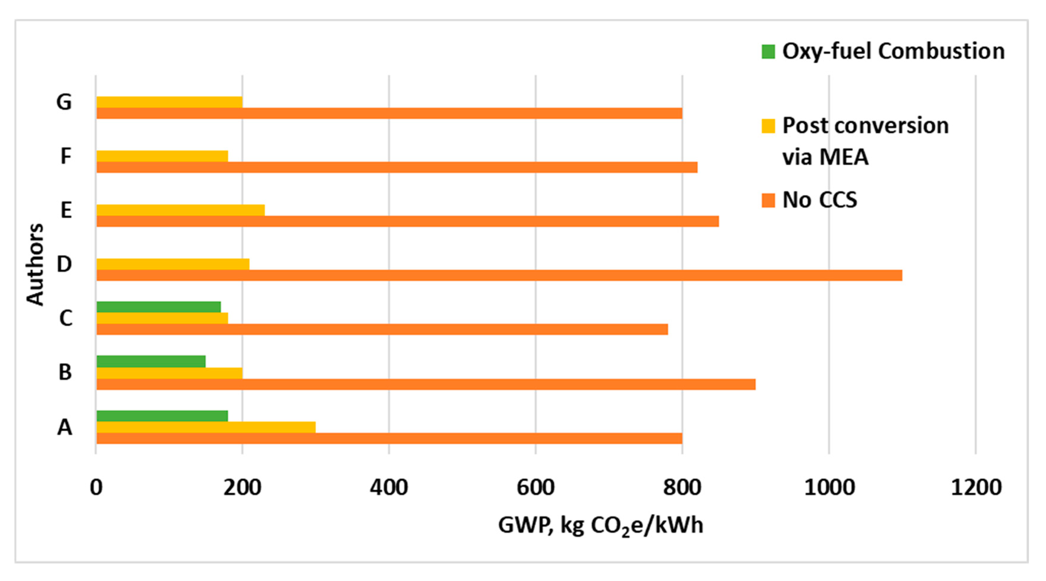
7.2. How Green Is CCUS: Life Cycle Analysis of CCUS Technologies

A standardized procedure for evaluating the environmental impacts of operational processes, products, and services through the life cycle (which includes stages, such as raw material extraction, manufacturing, transportation, use phase, maintenance, and disposal) from cradle-to-grave is Life Cycle Assessment (LCA) [181]. The up and down streams are connected by the input and output of the cycle as products move between processes and the natural environment [182]. The goal of LCA, thus, provides a comprehensive and quantitative (impact values) analysis of the environmental stressors linked with each of the stages [183]. Figure 20 simplifies a standard approach by ISO 14040 and 14044 [3,180] for implementing LCA. LCA can provide valuable insights and identify and assess the environmental impact of CCUS. There have been several LCAs conducted in previous years to evaluate the environmental impacts of operations with CCUS objectives. Impacts assessed in most cases are not limited to the global warming impact category or global warming potential (climate change), but other environmental stressors are also accounted for.

7.2.1. Life Cycle Assessment of CCS

Studies reviewed in this Section cover power production systems with traditional PC (pulverized coal), integrated gasification combined cycle (IGCC), natural gas combined cycle, and biomass integrated gasification combined cycle (BIGCC) power plant (Figure 21). The variations present in these studies are the types of CO2 capture techniques and fuel for combustion. Table 3 presents selected LCA studies conducted on various types of plants and different capture techniques. The functional units, assessment boundary, and sequestration type are also summarized.
Volkart et al. [184] (Table 3), through a comparative LCA analysis, studied the environmental performance of cement production, wood, and fossil power plants retrofitted with CCS and without CCS. A 68–92% reduction in GHG emissions was recorded for fossil power plants retrofitted with CCS; a 38–78% reduction for cement production with corresponding emission factors in the range of 0.41 kgCO2e to 0.15 kgCO2e as compared to 0.67 kgCO2e (without CCS). For power generation, GHG emissions were reduced to 70–190 kgCO2e/kWh, which is closer to renewable power generation techniques such as wind, which has an emission power factor of about 10 to 55 kgCO2e/kWh, and photovoltaic with 50 to 90 kgCO2e/kWh.
Table 3. Summary of LCA studies for CCS technologies.
Capture Technology
Plant TypePre-CombPost CombOxy-Fuel CombFunctional UnitLCA BoundarySequestrationReferences
1YYY0.001 MWhC2GvGF[184]
1 Y 0.001 MWhC2GvO[185]
1 Y 1 MWhC2GvO[186]
1 Y 1 tCO2G2Gt [187]
1YY 0.001 MWhC2GvO[188]
2YYY0.001 MWhG2GvGF[189]
1 Y 1 MWhC2GvGF[190]
1 Y 1 MWhC2Gv [191]
2Y C2GvGF[192]
1 Y 1 tCO2G2Gt [193]
3 YY1 MWhC2Gv [194]
4 Y 1 MWhC2GvGF[195]
1 Y 1 MWhC2Gt [196]
4 Y 1 MWhC2Gt [197]
Where (1) = Pulverized coal, (2) = Integrated Gasification Combined Cycle, (3) = Natural gas combined cycle, (4) = biomass integrated gasification combined cycle. C2Gv = cradle to Grave, C2Gt = Cradle to Gate, GF = Geological Formation, O = Ocean.
Figure 21. Schematic LCA boundary for a generalized power generation retrofitted with CCUS (adapted from [198]).
Energies 17 04248 g021
Tang Longlong et al. [185], for a pulverized coal power plant with CCS technology in Japan, used a LIME (life cycle impact assessment method based on end-point modeling) approach to assess the environmental impact based on three scenarios. (1) A typical ultra-supercritical pulverized coal-fired power plant, (2) with CCS systems, comprising Carbon capture with mono-ethanolamine solvent, compression, seafloor pipeline transportation, and Ocean storage. (3) Same as scenario 2, but with ship transportation. For case 1 without CCS, an estimate of 0.89 kgCO2e/kWh emission factor reordered with scenarios 2 and 3 estimating 0.18 (20% of case 1) and 0.26 kgCO2e/kWh (29% of case 1), respectively. However, tradeoffs for CCS technology feed increased other aspects of the endpoint impact assessment (human health, social asset, biodiversity, and primary production). Emissions of NH3 and ethylene oxide from the MEA production process in cases 2 and 3 lead to an increase in damage to biodiversity and primary production by forty percent. Zhang et al. [186], in an attempt to assess the performance of CCS technologies, performed an energetic and environmental impact assessment of three carbon capture cases from a coal power plant. MEA (case 1), membrane (case 2), and hybrid membrane cryogenic (case 3) separation processes. A base case without CCS was estimated at 767.6 kgCO2e/kWh. With CCS, emissions were reduced to 103.5, 98.5, and 97.7 kgCO2e/kWh for cases 1 to 3, respectively. However, other environmental factors were heavily negatively impacted. Ozone depletion potential (ODP), indicating the potential of chemicals with chlorine and bromine constituents to damage the stratospheric ozone, increased drastically in the three cases, in the range of 131% to 147%. A relative increment in other impacts such as eutrophication, ecotoxicity, acidification, and human toxicity was also estimated. MEA (CO2 absorption with amine base solvents) is one of the most advanced but also increases environmental impacts such as human toxicity [187]. Tim Grant et al. performed a LCA comparison between MEA and CO2CRC’s potassium carbonate bases UNO MK3 technique (assumes conventional steel columns for absorption and regeneration columns) (Table 3). A functional unit of 1 tonne CO2 separation from a brown coal-fired plant was introduced. The impact assessment for these techniques indicated from their work that there were two types of UNO MK3 separation techniques, where the second type assumes a concentric absorption or regeneration column design (concrete base) with a stainless-steel lining and an estimated smaller impact on all impact categories, including global warming potential. GWP estimates were as follows: 232 kgCO2e, 153 kgCO2e, and 152 kgCO2e for MEA, and 2 types of UNO MK3 techniques, respectively. All other impact categories recorded were below 50% lower than MEA, especially ecotoxicity and carcinogen emissions. The differences as reported were based on the amount of emissions recorded from the degradation of MEA as well as energy savings from the removal of CO2. Troy and Giordano [189] also performed a similar comparative LCA analysis with different capture and membrane separation techniques as against traditional separation methods. The authors concluded that membrane-based CCS technologies have a lower environmental impact compared to other CCS technologies, such as amine-based CCS.
Schakel et al. [188] found that, on an assessment of the impact of co-firing biomass in a coal-fired plant, where 30% based on energy is wood and straw pellets with CCS, a net negative emission of 67 to 85 kg/kWh was estimated, but it yielded an adverse impact on all other impact categories ranging from 20% to 200%. Per their findings, an endpoint aggregate level indicates the decrease in CO2 emissions more positively impacts the environment than the increase in other factors. With supercritical coal power plants enabled with CCS in China, Asante Okyere et al. [190] recorded a 71% drop in life cycle GHG emissions, with other impact categories showing tradeoffs for CCS as found in other literature. Through a cradle-to-grave LCA, including construction, operation, and decommissioning phases, Pertrescu et al. [191] accessed the use of post-combustion CCS technology in a supercritical pulverized coal power plant. The use of post-combustion CCS technologies reduces CO2 emissions by up to 90%, as well as other air pollutants, such as sulfur dioxide (SO2), nitrogen oxides (NOx), and particulate matter (PM).
With natural gas-fueled power plants based on chemical looping combustion (CLC) technology, Navajas et al. [194] indicated that the CLC technology can reduce the carbon footprint of natural gas-fueled power plants by up to 20 compared to traditional natural gas power plants. The study also identifies potential negative environmental impacts of the CLC system, including using rare metals in the CLC reactor and producing waste materials. To mitigate these negative environmental impacts, the authors suggest further research into developing alternative materials for the CLC reactor and implementing recycling and reusing strategies for waste materials. Overall, the study highlights the potential of CLC technology as a promising approach for reducing the environmental impact of natural gas-fueled power plants. GWP estimates of power plants with and without CCS are presented in Figure 22.

7.2.2. Environmental Impact Assessment of Carbon Capture and Utilization (CCU)

CO2 utilization has the potential to not only reduce greenhouse gas emissions but also create new economic opportunities and contribute to the transition to a more sustainable future. Some examples of CO2 utilization include Enhanced Oil Recovery (EOR), Mineralization, Chemical production, Building materials, and Agriculture. Table 4 summarizes various utilization sources of CO2. LCA was undertaken for the boundaries of each of these attempts to establish further the potential of CCUS. From Figure 23, the endpoint of utilization is a significant difference compared to CCS. CO2-EOR, however, can be classified as CCUS due to its dual advantage of recovering oil and at the same time, sequestering CO2 [202,203].
Khoo et al. [204] investigated the emissions and costs of mineral carbonation through LCA utilizing a case study from Singapore. The study realized a total CO2 avoidance between 106 and 175.2 kgCO2/1 MWh. Nduagu et [213] also analyzed the LCA of producing magnesium hydroxide (Mg(OH)2) for CO2 mineral sequestration. Though (Mg(OH)2) has a high CO2 conversion rate, their study estimated a GWP of 433 kg CO2e/t-CO2, which is an indication of certain inefficiencies in the process leading to losses in energy, hence rendering the life cycle estimates to be high. Figure 24 represents the GHG emission factors for seven different CO2-EOR sites [3]. Ref. [212] estimated in kgCO2e/bbl. the amount of crude oil produced. Based on these factors, a decision by operators whether to attain carbon neutral or negative can be taken. Niagaran Reef, though, has the second highest factor after a full LCA analysis, and estimating the net CO2 emission factor attained a net negative (−160 kt) [212]. Attaining carbon neutral or negative, thus, can be achieved, depending on how much CO2 is sequestered, even in CO2-EOR operations that have multi-objectives [30].

7.3. Socioeconomic and Sustainability Considerations

Implementing Carbon Capture, Utilization, and Storage (CCUS) technologies is both a technical and environmental endeavor and a socioeconomic one. The success of CCUS depends on various socioeconomic factors, including job creation, energy security, and public acceptance. This review explores these critical considerations, examining their implications for the broader adoption and sustainability of CCUS technologies.

7.3.1. Job Creation

Direct Employment Opportunities: Deploying CCUS technologies can create numerous direct job opportunities across various stages, including capture, transportation, utilization, and storage. According to a study by the Global CCS Institute, the construction and operation of CCUS facilities can generate significant employment in the engineering, manufacturing, and maintenance sectors [215]. For example, the Petra Nova project in Texas employed hundreds of workers during its construction phase and continues to provide operational jobs. Indirect and Induced Employment: CCUS can stimulate indirect and induced job creation beyond direct employment. Indirect jobs are generated in the supply chain, including producing materials and equipment necessary for CCUS infrastructure. Induced jobs arise from the increased economic activity resulting from the spending of incomes earned in direct and indirect jobs. Studies indicate that each job in the CCUS sector can create multiple additional jobs in the wider economy [97].
Skill Development and Workforce Transition: CCUS also plays a crucial role in transitioning the workforce from traditional fossil fuel industries to more sustainable energy sectors. Training programs and educational initiatives are essential to equip workers with the necessary skills for CCUS technologies. This transition can help mitigate the job losses associated with the decline of the coal and oil industries, providing new opportunities in the green economy [216].

7.3.2. Energy Security

Diversification of Energy Sources: CCUS enhances energy security by enabling the continued use of domestic fossil fuel resources in a more environmentally sustainable manner. By capturing and storing CO2 emissions from coal, oil, and natural gas power plants, CCUS allows a more gradual transition to renewable energy sources while maintaining energy reliability and stability [26]. This diversification helps reduce dependence on imported energy and enhances national energy independence. Stabilization of Energy Supply: One of the significant benefits of CCUS is its ability to stabilize the energy supply by providing a reliable backup for intermittent renewable energy sources. Natural gas plants equipped with CCUS can operate flexibly, ramping up production when wind or solar power is insufficient. This capability ensures a consistent and reliable energy supply, which is crucial for economic stability and growth [54]. Enhanced Oil Recovery (EOR): CCUS can also contribute to energy security through Enhanced Oil Recovery (EOR). Injecting captured CO2 into mature oil fields can increase oil production, extending the life of these fields and reducing the need for new oil exploration. While this approach does raise concerns about continued fossil fuel use, it can provide a transitional strategy to enhance energy security while developing renewable energy infrastructure [36,217].

7.3.3. Public Acceptance

Awareness and Perception: Public acceptance is a critical factor for successfully implementing CCUS projects. Public perception is influenced by awareness of CCUS technologies and their potential benefits and risks. Studies show that public knowledge about CCUS is generally low, and misconceptions about safety and environmental impacts can lead to opposition [218]. Effective communication and education strategies are essential to improve public understanding and acceptance.
Trust in Regulatory Frameworks: Public trust in the regulatory frameworks governing CCUS is crucial for acceptance. Strong regulations and transparent monitoring systems can alleviate public concerns about CO2 leakage and induced seismicity. For instance, the Sleipner project in Norway has gained public acceptance partly due to robust regulatory oversight and transparent reporting of monitoring results [219]. Building and maintaining public trust requires ongoing engagement and dialogue with communities.
Community Involvement and Benefits: Engaging local communities and ensuring they benefit from CCUS projects can enhance public acceptance. This involvement includes providing economic benefits such as job creation and infrastructure development and addressing community concerns through participatory decision-making processes. Successful CCUS projects often feature strong community relations and active involvement of local stakeholders in planning and implementation [220].

8. Case Studies and Pilot Projects

8.1. Overview of Prominent CCUS Projects Worldwide

Sleipner CO2 Storage Project, Norway: The Sleipner project, operated by Equinor, began in 1996 and is a pioneering initiative in carbon storage. Capturing approximately one million tonnes of CO2 annually from the Sleipner gas field, the project stores the gas in the Utsira Formation, a deep saline aquifer beneath the North Sea. Sleipner’s success is attributed to thorough site selection, robust monitoring systems, and a strong regulatory framework. It has become a benchmark for geological storage, providing valuable data on long-term CO2 behavior in subsurface conditions [219].
Boundary Dam Carbon Capture and Storage Project, Canada: The Boundary Dam project in Saskatchewan, Canada, represents a significant milestone as the world’s first large-scale CCS project integrated with a coal-fired power plant. Since its commissioning in 2014, the facility has captured about one million tonnes of CO2 annually. The captured CO2 is utilized for enhanced oil recovery (EOR) and stored in geological formations. The project demonstrates the technical feasibility of retrofitting existing coal plants with CCS technology but also highlights the challenges of high operational costs and economic sustainability [221].
Illinois Industrial CCS Project, USA: Operational since 2017, the Illinois Industrial CCS Project captures CO2 from the Archer Daniels Midland (ADM) ethanol production facility in Decatur, Illinois. The project sequesters the captured CO2 in the Mount Simon Sandstone, a deep saline aquifer. This project is significant for integrating bioenergy production, making it a model for Bioenergy with Carbon Capture and Storage (BECCS). Over its operational period, the project has demonstrated the potential for substantial greenhouse gas reductions in the bioenergy sector [222,223].
Petra Nova Carbon Capture Project, USA: The Petra Nova project, near Houston, Texas, began operations in 2017 as the largest post-combustion carbon capture facility. It captured approximately 1.6 million tonnes of CO2 annually from a coal-fired power plant. The captured CO2 was transported to the West Ranch oil field for EOR. Despite technological success, economic challenges led to the project’s suspension in 2020. The Petra Nova project underscores the need for economic viability alongside technological advancements in CCUS [35].
Quest Carbon Capture and Storage Project, Canada: The Quest project in Alberta captures CO2 from Shell’s Scotford Upgrader, which processes bitumen from oil sands. Since starting operations in 2015, Quest has captured and stored over five million tonnes of CO2. The project has been praised for its comprehensive monitoring and transparency, offering valuable insights into CO2 storage in saline aquifers. It is an essential model for integrating CCUS with oil sands operations, balancing industrial activity with carbon management [224]. Gorgon CO2 Injection Project, Australia: The Gorgon project, one of the largest natural gas projects globally, includes a significant CCUS component. Located on Barrow Island, the project captures CO2 from natural gas production and injects it into a deep saline aquifer. Since 2019, the project has aimed to capture and store around 3.4 to 4 million tonnes of CO2 annually. Gorgon highlights the challenges of implementing CCUS in remote and sensitive environmental areas, including managing potential CO2 leakage and ensuring minimal environmental impact [169].
Tomakomai CCS Demonstration Project, Japan: The Tomakomai project in Hokkaido, Japan, is a demonstration project that captures CO2 from a hydrogen production facility and stores it in offshore geological formations. Since its inception in 2016, the project has successfully injected over 300,000 tonnes of CO2. Tomakomai is a critical example of CCUS technology integration with industrial processes and offshore storage, providing valuable lessons for future offshore CCS projects in seismic regions [225].
Port Arthur CCS Project, USA: The Port Arthur project in Texas captures CO2 from two steam methane reformers used in hydrogen production at a Valero refinery. Operational since 2013, the captured CO2 is used for EOR. This project is significant for demonstrating the integration of CCS with hydrogen production, an essential element for the future hydrogen economy. The project has captured and utilized over 1 million tonnes of CO2, showcasing the potential for CCS in industrial applications beyond power generation [226].

Summary of U.S. Department of Energy (DOE) Sponsored Projects

DOE’s involvement in CCUS research and development dates back to the late 1990s initially centered on carbon capture technology for coal-fired power plants and underground geologic storage [227]. Congress further recommended that DOE expand toward capture for other sources and some types of carbon dioxide removal (or negative emission technologies). These new objectives were codified in the Infrastructure Investment and Jobs Act of 2021 and the Energy Act of 2020, division Z of P.L. 116–260, which served as the first significant amendment to DOE R&D program objectives since 2007 [227].
Early efforts and partnerships between 1997 and 2008 included establishing the Regional Carbon Sequestration Partnerships (RCSP, 2003) [228] program to develop and validate CCS technologies across geologic formations in the United States. An example of this partnership is the Southeast Regional Carbon Sequestration Partnership (SECARB), which conducted CO2 injection tests in saline reservoirs and coal seams in the southeastern U.S. [229]. Also, the Southwest Regional Partnership (SWP, 2003) was developed to demonstrate CCS technologies in the southwestern US, which focused on CO2-EOR and storage. The key demonstration site for this project is the Farnsworth Unit (FWU), where CO2 is used for enhanced oil recovery (EOR) and subsequent storage in the oil reservoir. This project demonstrates the potential for long-term CO2 storage in depleted oil fields (site all PRRC papers) [21,119,230,231,232,233]. The Carbon Sequestration Leadership Forum (CSLF, 2003) [234], an international initiative to advance CCS cost-effective technologies for CCS, also forms part of this early initiative by DOE.
The period between 2008 and 2016 saw other large-scale projects and technological advancements like the FutureGen 2.0 in 2009, which was to develop the world’s first near-zero emissions coal-fueled power plant retrofitted with CCS (1.3 million metric tons per year) in Meredosia, Illinois, but was canceled in 2015 due to funding and regulatory challenges (FutureGen Overview; FutureGen Cancellation) [235]. The Industrial Carbon Capture and Storage (ICCS) Program also streamed in 2010 to fund projects demonstrating large-scale CCS from industrial sources. The ADM Biogenic CCS project captures CO2 from bioethanol generation at Archer Daniels Midland’s Decatur, Illinois, operations with storage of about 1 million tons/yr. in deep saline formations [236]. The Air Products and Chemicals CCS project, which captures CO2 (about 1 million tons/yr.) from hydrogen production for EOR in the West Hastings Unit oil field [237], is a key project under the ICCS program.
Further, major DOE initiatives into new sectors saw the establishment of CarbonSAFE, National Carbon Capture Center (NCCC—hosted over 60 technology developers around the world to test various CO2 capture methods), and Carbon Utilization programs (CUP) in 2016 (e.g., NREL work on CO2 algae cultivation and CarbonCure Technologies work of CO2 concrete curing) [238]. The CarbonSafe objective is to develop and demonstrate CCS projects capable of storing over 50 million metric tons of CO2. The project has four phases: the Integrated CCS Pre-feasibility, storage complex feasibility, site characterization and permitting, and construction phases. Examples of this project are the CarbonSafe Illinois Storage Corridor and the Four Corners Carbon Storage Hub (CarbonSAFE Phase III project in the San Juan basin, which aims to store over 50 million metric tons in 30 years) [238].
Other key DOE CCUS developments include the Midwest Regional Carbon Sequestration Partnership (MRCSP), which is focused on building infrastructure in the Midwest US, by integrating CCS into functional industrial processes (MRCSP); The Plains CO2 Reduction (PCOR) Partnership, which also targets infrastructure development in the Plains region of US with a range of storage options (saline formations and depleted oil and gas fields) (PCOR site) [229]. DOE recently focused on accelerating CCS technology deployment with an emphasis on reducing costs and increasing the efficiency of capture technologies and expansion of utilization options. A key example is the Carbon Capture Pilot Plant at the University of Kentucky, which tests new solvent-based CO2 capture technologies [239] (University of Kentucky CO2 Capture Pilot Plant).

8.2. Lessons Learned from Successful and Unsuccessful Projects

8.2.1. Success Factors

Robust Regulatory Frameworks: Projects like Sleipner and Quest have thrived under solid regulatory oversight, ensuring rigorous environmental and safety standards. Such frameworks are essential for building public trust and securing long-term project viability [219].
Economic Incentives and Funding: Economic viability is crucial. Projects with significant government support, such as Boundary Dam and Illinois Industrial CCS, demonstrate that financial incentives and subsidies can make CCUS projects economically feasible and attractive to investors [221].
Technological Innovation and Adaptation: Technological advancements and integrating CCUS with existing infrastructure are pivotal. For example, the Petra Nova project successfully integrated post-combustion capture with EOR, although it faced economic sustainability challenges [35].

8.2.2. Challenges and Failures

Economic Viability: The suspension of Petra Nova highlights the importance of economic sustainability. High operational and maintenance costs, coupled with volatile oil prices affecting EOR revenues, can undermine project viability [35].
Public Acceptance: Public opposition due to environmental concerns and lack of awareness can hinder CCUS projects. Transparent communication and community engagement are vital to gaining public support and acceptance [220].
Technical and Logistical Issues: Technical failures and logistical challenges, such as CO2 leakage risks and the complexity of transporting CO2 over long distances, pose significant hurdles. Effective risk management and robust engineering solutions are crucial [179].

8.3. Implications for Future Deployment

Future CCUS projects must focus on reducing costs through technological innovations and achieving economies of scale. Government incentives, carbon pricing mechanisms, and private–public partnerships can enhance economic viability. Additionally, exploring revenue streams from CO2 utilization in chemicals, fuels, and building materials can provide financial sustainability [58].
Robust regulatory frameworks that ensure safe CO2 storage and effective monitoring are essential. International standards and collaboration can facilitate the global deployment of CCUS technologies. Policies promoting the use of low-carbon energy sources for CCUS operations can further enhance sustainability [26].
Building public trust through transparent communication, community engagement, and education about the benefits and risks of CCUS is crucial. Successful case studies should be highlighted to demonstrate the feasibility and safety of CCUS technologies [218].
Future deployments should explore the integration of CCUS with renewable energy systems, such as using renewable energy to power CO2 capture processes or combining CCUS with biomass energy (BECCS). This approach can maximize the environmental benefits and support the transition to a low-carbon economy [142].
Advanced monitoring and digital technologies can enhance the efficiency and safety of CCUS projects. Continuous monitoring systems can detect and mitigate CO2 leakage, ensuring the integrity of storage sites. Leveraging big data and artificial intelligence can optimize CCUS operations and reduce costs [219].

9. Research Gaps and Future Directions of CCUS

Table 5, Table 6 and Table 7 provide a clear summary of various research gaps, opportunities for innovation and development, and recommendations for future directions. By addressing these gaps and seizing the opportunities for innovation, the field of CCUS can advance significantly, contributing to global efforts to mitigate climate change and transition to a low-carbon economy.

10. Conclusions

This review comprehensively analyzes CCUS technologies, illustrating their pivotal role in reducing global CO2 emissions. Key findings include the following:
Various carbon capture methods, such as pre-combustion, post-combustion, and oxy-fuel combustion, offer distinct advantages and face unique challenges. While significant advancements have been made in capture efficiency, cost reduction remains a critical challenge. Direct and indirect carbon utilization methods present valuable opportunities for converting captured CO2 into useful products. However, technological limitations and economic feasibility are major hurdles that need to be addressed to scale these applications. Geological storage, including saline aquifers and depleted reservoirs, shows the most promise in capacity and feasibility. Nonetheless, long-term monitoring and environmental safety remain paramount concerns that necessitate further research. Effective policies and regulatory frameworks are essential to incentivize CCUS deployment. Current frameworks provide a foundation, but significant opportunities exist to enhance support mechanisms and address regulatory challenges. While the cost of CCUS technologies is a significant barrier, emerging market trends and investment outlooks indicate growing interest and potential for economic solutions. Innovative funding mechanisms and economic models are crucial for overcoming these barriers. CCUS technologies offer substantial environmental benefits by mitigating CO2 emissions. However, comprehensive life cycle analyses and sustainability assessments are essential to ensure these technologies do not pose unintended environmental risks.
The findings of this review underscore the need for continued research and innovation in CCUS technologies. Addressing the identified knowledge gaps, such as improving capture efficiency, reducing costs, and ensuring long-term storage security, is essential for the advancement of CCUS. Additionally, fostering interdisciplinary research, enhancing public engagement, and developing robust policy frameworks will be critical in facilitating the broader deployment of CCUS technologies.
CCUS technologies are indispensable tools in the global effort to combat climate change. While significant progress has been made, continued investment in research, development, and policy support is essential to realize the full potential of CCUS. By addressing current challenges and seizing opportunities for innovation, CCUS can play a crucial role in achieving a sustainable and low-carbon future.

Author Contributions

Conceptualization, W.A.; methodology, W.A. and A.M.; software, W.A. and A.M.; validation, W.A. and A.M.; formal analysis, W.A. and A.M.; investigation, W.A. and A.M.; resources, W.A.; data curation, W.A. and A.M; writing—original draft preparation, W.A., A.M., and D.O.K.; writing—review and editing, W.A., A.M., D.O.K., and W.I.N.; visualization, W.A., A.M., D.O.K., and W.I.N.; supervision, W.A.; project administration, W.A.; funding acquisition, W.A. All authors have read and agreed to the published version of the manuscript.

Funding

Funding for this project is provided by the U.S. Department of Energy’s (DOE) National Energy Technology Laboratory (NETL) through the Southwest Regional Partnership on Carbon Sequestration (SWP) under Award No. DE-FC26-05NT42591.

Acknowledgments

We thank the U.S. DOE for providing the funding support for this work and the Petroleum Recovery and Research Center, New Mexico Tech for providing additional support and resources. We also thank MDPI editorial team and anonymous reviewers for their helpful comments on this article.

Conflicts of Interest

The authors declare no conflicts of interest.

Appendix A. Summary of CCUS Projects Worldwide

Table A1. Active and ongoing projects or completed Projects.
No.Project NameLocationStartCapacityDescription
1Boundary Dam
CCS
Saskatchewan,
Canada
20141 Mt/yr.Captures CO2 emissions from a coal-fired power plant and stores them underground.
2Petra Nova
Carbon Capture
Texas,
USA
20171.6 Mt/yr.Captures CO2 emissions from a coal-fired power plant and utilizes them for enhanced oil recovery.
3Sleipner CCS North Sea,
Norway
199620 M to dateCaptures CO2 emissions from natural gas production and stores them underground. World’s first commercial CCS project.
4Quest CCSAlberta, Canada20151.1 Mt/yr.Captures CO2 emissions from an oil sands upgrader and stores them underground.
5Gorgon CCSWestern
Australia
20194 Mt/yr.Captures CO2 emissions from a natural gas processing plant and stores them underground.
6Weyburn-Midale
CO2
Saskatchewan,
Canada
20001.8 Mt/yr.Involves the injection of captured
CO2 into oil fields for secondary oil recovery.
7In Salah Gas CCSAlgeria200417 Mt inj.Captures and stores CO2 emissions
from natural gas production.
8Troll Gas CCS North Sea,
Norway
19962 MtCaptures CO2 emissions from a natural gas processing facility and stores them underground.
9Decatur Carbon Capture Illinois,
USA
20171 MT/yr.Captures CO2 emissions from an ethanol production facility and stores them underground.
10Mountaineer CCS Project West Virginia,
USA
20090.1 MtA pilot project aimed to capture CO2 emissions from a coal-fired power plant for storage underground.
11Saline Aquifer Storage Site Project Otway Basin,
Australia
2008ResearchInvolves the injection of captured CO2 into a saline aquifer for storage and monitoring.
12Southwest Regional Carbon Sequestration Partnership (SWP) Projects USA2000variable capacitiesA collaborative effort among industry, government, and research institutions to study and demonstrate carbon capture and storage in the southwestern United States.
13Interstate Oil and Gas Compact
Commission (IOGCC) CCS Projects
USA A collaborative effort among states to promote and facilitate the development of CCS projects
in the oil and gas industry.
14Midwest Geological Sequestration
Consortium (MGSC) Projects
USA2000variable capacitiesA consortium focused on studying geological CO2 storage in the Midwest region of the United States.
15Carbon Sequestration Leadership
Forum (CSLF) Projects
International2003variable capacitiesAn international collaboration to advance CCS technologies and practices through knowledge sharing and research.
16Alberta Carbon Trunk Line (ACTL) CCS Project Alberta,
Canada
2020 A project aimed at capturing CO2 emissions from industrial sources and transporting them via pipeline for enhanced oil recovery.
17Tomakomai CCS Demonstration Project Hokkaido,
Japan
2016 Involves capturing CO2 emissions from a hydrogen plant and storing them underground.
18CO2CRC Otway Project Otway Basin,
Australia
Involves the injection of captured CO2 into a saline aquifer for storage and monitoring.
19SaskPower Boundary Dam CCS Project Saskatchewan,
Canada
20141 Mt/yr.Captures CO2 emissions from a coal-fired power plant and stores them underground.
20Saline Aquifer Storage Site ProjectKetzin,
Germany
2008 A research project aimed at studying the feasibility of storing CO2 in a saline aquifer formation.
21North West Redwater Sturgeon Refinery
CCS Project
Alberta,
Canada
The Sturgeon Refinery is one of the first refineries in the world designed from the ground up to incorporate carbon capture and storage (CCS) technology.
22Hellisheidi CCS Project Iceland201412,000 t/yr.This project captures CO2 emissions from a geothermal power plant and stores them underground by mineralizing the CO2 into basalt rock.
23Petrobras CO2 Injection ProjectBrazil2010 This project involves the injection of captured CO2 for enhanced oil recovery in offshore oil fields. First CCUS project in ultra-deep waters. Currently the largest CO2 injection project in the world (annual reinjection).
24Questerre ProjectAlberta,
Canada
Aimed at capturing and storing CO2 from shale gas production operations.
25LaBarge CCS ProjectWyoming,
USA
The project captures CO2 emissions from a natural gas processing plant and stores them underground in a saline aquifer.
Table A2. Projects Under development.
NoProject NameLocationStatusCapacityDescription
1Northern Lights CCS ProjectNorwayCurrently in development A full-chain CCS project aiming to capture CO2
emissions from industrial sources and store them offshore.
2Acorn CCS ProjectScotland, UK A project aiming to develop a full-chain CCS system, including capture, transportation, and storage in depleted oil and gas fields.
3Carson Hydrogen Power
Plant CCS Project
Under developmentUnder development Planned to capture CO2 emissions from a hydrogen production
plant and store them underground.
4Carbon Capture Project Utah, USAProject ongoing Aimed at capturing CO2 emissions from industrial sources for
storage underground in deep saline formations.
5Carson CCS Project California, USA A project aimed at capturing CO2 emissions from a cement plant and storing them underground.
6Val Verde CCS Project Texas, USA Aimed at capturing CO2 emissions from industrial sources for storage underground.
7Huntly Power Station CCS Project under consideration Proposed project aiming to capture CO2 emissions from a power plant for storage underground.
8Carlsbad CCS Project New Mexico, USAunder development Aimed at capturing CO2 emissions from industrial sources for storage underground.
9CarbonNet Project Victoria, Australia A project aiming to capture and store CO2 emissions from industrial sources in the Gippsland Basin.
10Wabash Valley Resources CCS Project Indiana, USA Aimed at capturing CO2 emissions from a fertilizer plant for storage underground.
11Netherlands—ROAD Project Rotterdam, Netherlands Aimed at establishing a CO2 transport and storage infrastructure to support emissions reduction in the Rotterdam area.
12Porthos CCS Project Rotterdam, Netherlands A project aiming to develop a shared CO2 transport and storage infrastructure to reduce emissions in the region.
13H21 North of England CCS Project United Kingdom A proposed project aiming to decarbonize industrial clusters in the north of England, utilizing CCS technology.
14Amager Bakke CCS Project Copenhagen, Denmark 0.5 Mt/yr.A project aiming to capture CO2 emissions from a waste-to-energy plant for storage underground.
15Tianjin CCS Project Tianjin, China Aimed at capturing CO2 emissions from a coal-fired power plant and storing them underground.
16Project Tundra CCS Project North Dakota, USAfinal project development phaseUp to 4 million metric tons annuallyA proposed project aiming to capture CO2 emissions from
a coal-fired power plant for storage underground.
17Tulsa Regional Carbon Capture
& Sequestration (CCS) Project
Oklahoma, USA A project aimed at studying the feasibility of CCS in the Tulsa region, focusing on industrial emissions.
18Port Arthur CCS ProjectTexas, USA Planned as part of a refinery expansion project, aiming to capture and store around 1.5 million tonnes of CO2 per year underground.
Table A3. Terminated Projects.
NoProject NameLocationStatusCapacityDescription
1Natchez CCS Project Mississippi, USAcanceled in 20171.5 Mt/yr.Planned to capture CO2 emissions from a coal-fired power
plant for storage underground.
2Hydrogen Energy California
(HECA) CCS Project
California, USAcanceled in 20172.5 Mt/yr.Planned as an integrated gasification combined cycle
(IGCC) coal-fired power plant with CCS for enhanced oil recovery.
3Texas Clean Energy Project Texas, USAdiscontinued2.7 Mt/yr.Originally planned as an IGCC coal-fired power plant with CCS for enhanced oil recovery.
4Peterhead CCS Project Scotland, UKcanceled in 2015 Planned to capture CO2 emissions from a power plant and store them in depleted gas fields beneath the North Sea.
5Kemper County Energy
Facility CCS Project
Mississippi, USAProject transitioned to
natural gas without CCS
3.5 Mt/yr.Originally intended as a coal gasification plant with integrated CCS for enhanced oil recovery.
Hazelwood CCS ProjectVictoria, Australia Proposed as a retrofit to a coal-fired power plant, aiming to capture CO2 emissions for storage underground.
However, the project did not proceed beyond the planning stage.
Lake Charles CCS Project Cancelled in October 20144.5 Mt/yr.

References

  1. IEA Fact Sheet and Analysis. 2015. Available online: https://www.iea-shc.org/fact-sheets (accessed on 20 November 2023).
  2. DOE/NETL Advanced Carbon Dioxide R&D Program: Technology Update. 2011. (p. 118). National Energy Technology Laboratory. Available online: http://www.netl.doe.gov/technologies/coalpower/ewr/pubs/CO2Handbook (accessed on 26 November 2023).
  3. Morgan, A.; Grigg, R.; Ampomah, W. A Gate-to-Gate Life Cycle Assessment for the CO2-EOR Operations at Farnsworth Unit (FWU). Energies 2021, 14, 2499. [Google Scholar] [CrossRef]
  4. CO2CRC. Report, CO2CRC Annual, 2022/2023 20th Anniversary. 2023. Available online: https://co2crc.com.au/wp-content/uploads/2023/11/CO2CRC-Annual-Report-22-23.pdf (accessed on 17 January 2024).
  5. Brown, K.; Whittaker, S.; Wilson, M.; Srisang, W.; Smithson, H.; Tontiwachwuthikul, P. The history and development of the IEA GHG Weyburn-Midale CO2 Monitoring and Storage Project in Saskatchewan, Canada (the world largest CO2 for EOR and CCS program). Petroleum 2017, 3, 3–9. [Google Scholar] [CrossRef]
  6. Intergovernmental Panel on Climate Change. Global Warming of 1.5°C. An IPCC Special Report on the Impacts of Global Warming of 1.5°C above Pre-Industrial Levels and related Global Greenhouse Gas Emission Pathways, in the Context of Strengthening the Global Response to the Threat of Climate Change; IPPC: Geneva, Switzerland, 2018. [Google Scholar]
  7. GML. Carbon Cycle Greenhouse Gases. Available online: https://gml.noaa.gov/ccgg/ (accessed on 12 February 2024).
  8. National Oceanic and Atmospheric Administration (NOAA). Despite pandemic shutdowns, carbon dioxide and methane surged in 2020. Available online: https://research.noaa.gov/2021/04/07/despite-pandemic-shutdowns-carbon-dioxide-and-methane-surged-in-2020/ (accessed on 19 March 2024).
  9. IPCC Special Report on Carbon Dioxide Capture and Storage. Prepared by Working Group III of the Intergovernmental Panel on Climate Change. 2005. Available online: https://www.ipcc.ch/report/carbon-dioxide-capture-and-storage/ (accessed on 5 January 2024).
  10. NOAA, Global Monitoring Laboratory; Trends in atmospheric carbon dioxide (CO2). Available online: https://gml.noaa.gov/ccgg/trends/ (accessed on 20 February 2024).
  11. Nath, F.; Mahmood, M.N.; Yousuf, N. Recent advances in CCUS: A critical review on technologies, regulatory aspects and economics. Geoenergy Sci. Eng. 2024, 238, 212726. [Google Scholar] [CrossRef]
  12. Singh, J.D.; Wattal, D. Overview of Carbon Capture Technology: Microalgal Biorefinery Concept and State-of-the-Art. Front. Mar. Sci. 2019, 6, 29. [Google Scholar] [CrossRef]
  13. Kelemen, P.; Benson, S.; Pilorgé, H.; Psarras, P.C.; Wilcox, J. An Overview of the Status and Challenges of CO2 Storage in Minerals and Geological Formations. Front. Clim. 2019, 1, 9. [Google Scholar] [CrossRef]
  14. IEA. Net zero by 2050, IEA, Paris. Available online: https://www.iea.org/reports/net-zero-by-2050 (accessed on 10 January 2024).
  15. Martin-Roberts, E.; Scott, V.; Flude, S.; Johnson, G.; Haszeldine, R.S.; Gilfillan, S. Carbon capture and storage at the end of a lost decade. One Earth 2021, 4, 1569–1584. [Google Scholar] [CrossRef]
  16. GCB. Country Chart Figures Contain Data on Land Use Emissions and Fossil Fuel Emissions. Global Carbon Budget. 2023. Available online: https://globalcarbonbudget.org/carbonbudget2023/ (accessed on 6 April 2024).
  17. Gale, J.; Metz, B.; Davidson, O.; de Coninck, H.; Loos, M.; Meyer, L. Carbon Dioxide Capture and Storage. Intergovernmental Panel on Climate Change; IPPC: Geneva, Switzerland, 2005. [Google Scholar]
  18. Scott, V.; Gilfillan, S.; Markusson, N.; Chalmers, H.; Haszeldine, R.S. Last chance for carbon capture and storage. Nat. Clim. Chang. 2012, 3, 105–111. [Google Scholar] [CrossRef]
  19. Lu, J.; Wilkinson, M.; Haszeldine, R.S.; Fallick, A.E. Long-term performance of a mudrock seal in natural CO2 storage. Geology 2009, 37, 35–38. [Google Scholar] [CrossRef]
  20. Juanes, R.; Hager, B.H.; Herzog, H.J. No geologic evidence that seismicity causes fault leakage that would render large-scale carbon capture and storage unsuccessful. Proc. Natl. Acad. Sci. USA 2012, 109, 201215026. [Google Scholar] [CrossRef]
  21. Ampomah, W.; Acheampong, S.A.; McMillan, M.; Bratton, T.; El-Kaseeh, G. Development of a Machine Learning Assisted Framework in Calibrating In-situ Stress Changes Through Time-lapse Vertical Seismic Profiling. In Proceedings of the 16th International Conference on Greenhouse Gas Control Technologies GHGT-16, Lyon, France, 23–24 October 2022. [Google Scholar] [CrossRef]
  22. Global CCSInstitute. Global Status of CCS Report: 2020. Available online: https://www.globalccsinstitute.com/wp-content/uploads/2021/03/Global-Status-of-CCS-Report-English.pdf (accessed on 5 December 2023).
  23. Bachu, S. Screening and ranking of sedimentary basins for sequestration of CO2 in geological media in response to climate change. Environ. Geol. 2003, 44, 277–289. [Google Scholar] [CrossRef]
  24. Ma, J.; Li, L.; Wang, H.; Du, Y.; Ma, J.; Zhang, X.; Wang, Z. Carbon Capture and Storage: History and the Road Ahead. Engineering 2022, 14, 33–43. [Google Scholar] [CrossRef]
  25. Ampomah, W.; Balch, R.S.; Cather, M.; Will, R.; Gunda, D.; Dai, Z.; Soltanian, M.R. Optimum design of CO2 storage and oil recovery under geological uncertainty. Appl. Energy 2017, 195, 80–92. [Google Scholar] [CrossRef]
  26. IEA. CCUS in Clean Energy Transitions. Available online: https://www.iea.org/reports/ccus-in-clean-energy-transitions (accessed on 28 January 2024).
  27. Madejski, P.; Chmiel, K.; Subramanian, N.; Kuś, T. Methods and Techniques for CO2 Capture: Review of Potential Solutions and Applications in Modern Energy Technologies. Energies 2022, 15, 887. [Google Scholar] [CrossRef]
  28. Hong, W.Y. A techno-economic review on carbon capture, utilisation and storage systems for achieving a net-zero CO2 emissions future. Carbon Capture Sci. Technol. 2021, 3, 100044. [Google Scholar] [CrossRef]
  29. You, J.; Ampomah, W.; Morgan, A.; Sun, Q.; Huang, X. A comprehensive techno-eco-assessment of CO2 enhanced oil recovery projects using a machine-learning assisted workflow. Int. J. Greenh. Gas Control. 2021, 111, 103480. [Google Scholar] [CrossRef]
  30. Morgan, A.; Ampomah, W.; Grigg, R.; Dai, Z.; You, J.; Wang, S. Echno-economic life cycle assessment of CO2-EOR operations towards net negative emissions at farnsworth field unit. Fuel 2023, 342, 127897. [Google Scholar] [CrossRef]
  31. EPA. Current Class VI Projects under Review at EPA. U.S. Environmental Protection Agency. Available online: https://www.epa.gov/uic/current-class-vi-projects-under-review-epa (accessed on 28 June 2024).
  32. EPA. Table of EPA’s Draft and Final Class VI Well Permits. U.S. Environmental Protection Agency. Available online: https://www.epa.gov/uic/table-epas-draft-and-final-class-vi-well-permits (accessed on 30 April 2024).
  33. GCCSI. U.S. EPA Releases Class VI Well Permit Dashboard and Data Repository. Global CCS institute. Available online: https://www.globalccsinstitute.com/news-media/latest-news/u-s-epa-releases-class-vi-well-permit-dashboard-and-data-repository/ (accessed on 30 April 2024).
  34. CRC. Carbon TerraVault Provides 2023 Update. California Resources Corporation. Available online: https://crc.com/news/news-details/2024/Carbon-TerraVault-Provides-2023-Update/default.aspx (accessed on 30 April 2024).
  35. NETL. NETL-Supported Petra Nova Project Celebrates Three Years of Sustainable Operation. Available online: https://www.netl.doe.gov/node/9405 (accessed on 5 March 2024).
  36. Ampomah, W.; Balch, R.S.; Grigg, R.B.; Will, R.; Dai, Z.; White, M.D. Farnsworth Field CO2-EOR Project: Performance Case History. In Proceedings of the SPE Improved Oil Recovery Conference, Tulsa, OK, USA, 11–13 April 2016; Society of Petroleum Engineers: Tulsa, OK, USA, 2016; Volume 18. [Google Scholar] [CrossRef]
  37. Kheirinik, M.; Ahmed, S.; Rahmanian, N. Comparative Techno-Economic Analysis of Carbon Capture Processes: Pre-Combustion, Post-Combustion, and Oxy-Fuel Combustion Operations. Sustainability 2021, 13, 13567. [Google Scholar] [CrossRef]
  38. Kearns, D.; Liu, H.; Consoli, C. Technology readiness and costs of CCS. Glob. CCS Inst. 2021, 3, 6–43. [Google Scholar]
  39. Beck, L. Carbon capture and storage in the USA: The role of US innovation leadership in climate-technology commercialization. Clean Energy 2019, 4, 2–11. [Google Scholar] [CrossRef]
  40. C. Beumelburg. Heidelberg Cement’ Commitment to Carbon Abatement. Available online: https://www.heidelbergmaterials.com/en/sustainability/we-decarbonize-the-construction-industry (accessed on 12 April 2024).
  41. GCCSI. Global Status of CCS 2021. Available online: https://www.globalccsinstitute.com/wp-content/uploads/2021/10/2021-Global-Status-of-CCS-Report_Global_CCS_Institute.pdf (accessed on 7 March 2024).
  42. Gomilšek, R.; Čuček, L.; Homšak, M.; Tan, R.R.; Kravanja, Z. Carbon Emissions Constrained Energy Planning for Aluminum Products. Energies 2020, 13, 2753. [Google Scholar] [CrossRef]
  43. Worth, K.; White, D.; Chalaturnyk, R.; Sorensen, J.; Hawkes, C.; Rostron, B.; Johnson, J.; Young, A. Aquistore Project Measurement, Monitoring, and Verification: From Concept to CO2 Injection. Energy Procedia 2014, 63, 3202–3208. [Google Scholar] [CrossRef]
  44. Wang, X.; Song, C. Carbon Capture From Flue Gas and the Atmosphere: A Perspective. Front. Energy Res. 2020, 8, 560849. [Google Scholar] [CrossRef]
  45. Khalilpour, R.; Mumford, K.; Zhai, H.; Abbas, A.; Stevens, G.; Rubin, E.S. Membrane-based carbon capture from flue gas: A review. J. Clean. Prod. 2015, 103, 286–300. [Google Scholar] [CrossRef]
  46. Eide, L.I.; Bailey, D.W. Precombustion Decarbonisation Processes. Oil Gas Sci. Technol. 2005, 60, 475–484. [Google Scholar] [CrossRef]
  47. Zhai, H.; Rubin, E.S. Systems Analysis of Ionic Liquids for Post-combustion CO2 Capture at Coal-fired Power Plants. Energy Procedia 2014, 63, 1321–1328. [Google Scholar] [CrossRef]
  48. Rubin, E.S.; Mantripragada, H.; Marks, A.; Versteeg, P.; Kitchin, J. The outlook for improved carbon capture technology. Prog. Energy Combust. Sci. 2012, 38, 630–671. [Google Scholar] [CrossRef]
  49. Wienchol, P.; Szlęk, A.; Ditaranto, M. Waste-to-energy technology integrated with carbon capture—Challenges and opportunities. Energy 2020, 198, 117352. [Google Scholar] [CrossRef]
  50. Herzog, H.; Golomb, D. Carbon Capture and Storage from Fossil Fuel Use. Encycl. Energy 2004, 1, 277–287. [Google Scholar]
  51. López, R.; Fernández, C.; Martínez, O.; Sánchez, M.E. Techno-economic analysis of a 15 MW corn-rape oxy-combustion power plant. Fuel Process. Technol. 2016, 142, 296–304. [Google Scholar] [CrossRef]
  52. Portillo, E.; Alonso-Fariñas, B.; Vega, F.; Cano, M.; Navarrete, B. Alternatives for oxygen-selective membrane systems and their integration into the oxy-fuel combustion process: A review. SePurif. Technol. 2019, 229, 115708. [Google Scholar] [CrossRef]
  53. Ma, Y.; Liao, Y.; Su, Y.; Wang, B.; Yang, Y.; Ji, D.; Li, H.; Zhou, H.; Wang, D. Comparative Investigation of Different CO2 Capture Technologies for Coal to Ethylene Glycol Process. Processes 2021, 9, 207. [Google Scholar] [CrossRef]
  54. Rosa, L.; Sanchez, D.L.; Mazzotti, M. Assessment of carbon dioxide removal potential via BECCS in a carbon-neutral Europe. Energy Environ. Sci. 2021, 14, 3086–3097. [Google Scholar] [CrossRef]
  55. Ashkanani, H.E.; Wang, R.; Shi, W.; Siefert, N.S.; Thompson, R.L.; Smith, K.; Steckel, J.A.; Gamwo, I.K.; Hopkinson, D.; Resnik, K.; et al. Levelized Cost of CO2 Captured Using Five Physical Solvents in Pre-combustion Applications. Int. J. Greenh. Gas Control 2020, 101, 103135. [Google Scholar] [CrossRef]
  56. Abuelgasim, S.; Wang, W.; Abdalazeez, A. A brief review for chemical looping combustion as a promising CO2 capture technology: Fundamentals and progress. Sci. Total Environ. 2020, 764, 142892. [Google Scholar] [CrossRef]
  57. Moldenhauer, P.; Linderholm, C.; Rydén, M.; Lyngfelt, A. Avoiding CO2 capture effort and cost for negative CO2 emissions using industrial waste in chemical-looping combustion/gasification of biomass. Mitig. Adapt. Strateg. Glob. Chang. 2019, 25, 1–24. [Google Scholar] [CrossRef]
  58. Rubin, E.S.; Davison, J.E.; Herzog, H.J. The cost of CO2 capture and storage. Int. J. Greenh. Gas Control 2015, 40, 378–400. [Google Scholar] [CrossRef]
  59. Joshi, A.; Shah, V.; Mohapatra, P.; Kumar, S.; Joshi, R.K.; Kathe, M.; Qin, L.; Tong, A.; Fan, L.-S. Chemical looping-A perspective on the next-gen technology for efficient fossil fuel utilization. Adv. Appl. Energy 2021, 3, 100044. [Google Scholar] [CrossRef]
  60. Zhang, X.; Zhao, H.; Yang, Q.; Yao, M.; Wu, Y.-N.; Gu, Y. Direct air capture of CO2 in designed metal-organic frameworks at lab and pilot scale. Carbon Capture Sci. Technol. 2023, 9, 100145. [Google Scholar] [CrossRef]
  61. Keith, D.W.; Holmes, G.; St. Angelo, D.; Heidel, K. A Process for Capturing CO2 from the Atmosphere. Joule 2018, 2, 1573–1594. [Google Scholar] [CrossRef]
  62. Li, B.; Duan, Y.; Luebke, D.; Morreale, B. Advances in CO2 capture technology: A patent review. Appl. Energy 2013, 102, 1439–1447. [Google Scholar] [CrossRef]
  63. Boot-Handford, M.E.; Abanades, J.C.; Anthony, E.J.; Blunt, M.J.; Brandani, S.; Mac Dowell, N.; Fernández, J.R.; Ferrari, M.-C.; Gross, R.; Hallett, J.P.; et al. Carbon capture and storage update. Energy Environ. Sci. 2014, 7, 130–189. [Google Scholar] [CrossRef]
  64. Dubey, A.; Arora, A. Advancements in carbon capture technologies: A review. J. Clean. Prod. 2022, 373, 133932. [Google Scholar] [CrossRef]
  65. Chamwudhiprecha, N.; Blunt, M.J. CO2 Storage Potential in the North Sea. In Proceedings of the International Petroleum Technology Conference, Bangkok, Thailand, 15 November 2011. [Google Scholar] [CrossRef]
  66. Otitoju, O.; Oko, E.; Wang, M. Technical and economic performance assessment of post-combustion carbon capture using piperazine for large scale natural gas combined cycle power plants through process simulation. Appl. Energy 2021, 292, 116893. [Google Scholar] [CrossRef]
  67. Rochelle, G.T. Amine Scrubbing for CO2 Capture. Science 2009, 325, 1652–1654. [Google Scholar] [CrossRef]
  68. Xu, G.; Liang, F.; Yang, Y.; Hu, Y.; Zhang, K.; Liu, W. An Improved CO2 Separation and Purification System Based on Cryogenic Separation and Distillation Theory. Energies 2014, 7, 3484–3502. [Google Scholar] [CrossRef]
  69. Leung, D.Y.C.; Caramanna, G.; Maroto-Valer, M.M. An overview of current status of carbon dioxide capture and storage technologies. Renew. Sustain. Energy Rev. 2014, 39, 426–443. [Google Scholar] [CrossRef]
  70. Cheng, C.-Y.; Kuo, C.-C.; Yang, M.-W.; Zhuang, Z.-Y.; Lin, P.-W.; Chen, Y.-F.; Yang, H.-S.; Chou, C.-T. CO2 Capture from Flue Gas of a Coal-Fired Power Plant Using Three-Bed PSA Process. Energies 2021, 14, 3582. [Google Scholar] [CrossRef]
  71. Sumida, K.; Rogow, D.L.; Mason, J.A.; McDonald, T.M.; Bloch, E.D.; Herm, Z.R.; Bae, T.-H.; Long, J.R. Carbon Dioxide Capture in Metal–Organic Frameworks. Chem. Rev. 2012, 112, 724–781. [Google Scholar] [CrossRef]
  72. Seoane, B.; Coronas, J.; Gascon, I.; Benavides, M.E.; Karvan, O.; Caro, J.; Kapteijn, F.; Gascon, J. Metal–organic framework based mixed matrix membranes: A solution for highly efficient CO2 capture? Chem. Soc. Rev. 2015, 44, 2421–2454. [Google Scholar] [CrossRef]
  73. Plaza, M.G.; García, S.; Rubiera, F.; Pis, J.J.; Pevida, C. Post-combustion CO2 capture with a commercial activated carbon: Comparison of different regeneration strategies. Chem. Eng. J. 2010, 163, 41. [Google Scholar] [CrossRef]
  74. Jiang, N.; Shen, Y.; Liu, B.; Zhang, D.; Tang, Z.; Li, G.; Fu, B. CO2 capture from dry flue gas by means of VPSA, TSA and TVSA. J. CO2 Util. 2020, 35, 153–168. [Google Scholar] [CrossRef]
  75. Yuan, Z.; Eden, M.R.; Gani, R. Toward the Development and Deployment of Large-Scale Carbon Dioxide Capture and Conversion Processes. Ind. Eng. Chem. Res. 2015, 55, 3383–3419. [Google Scholar] [CrossRef]
  76. Zhao, L.; Riensche, E.; Blum, L.; Stolten, D. Multi-stage gas separation membrane processes used in post-combustion capture: Energetic and economic analyses. J. Memb. Sci. 2010, 359, 160–172. [Google Scholar] [CrossRef]
  77. Al-Mamoori, A.; Krishnamurthy, A.; Rownaghi, A.A.; Rezaei, F. Carbon Capture and Utilization Update. Energy Technol. 2017, 5, 834–849. [Google Scholar] [CrossRef]
  78. He, X.; Fu, C.; Hägg, M.-B. Membrane system design and process feasibility analysis for CO2 capture from flue gas with a fixed-site-carrier membrane. Chem. Eng. J. 2015, 268, 1–9. [Google Scholar] [CrossRef]
  79. Ghalei, B.; Sakurai, K.; Kinoshita, Y.; Wakimoto, K.; Isfahani, A.P.; Song, Q.; Doitomi, K.; Furukawa, S.; Hirao, H.; Kusuda, H.; et al. Enhanced selectivity in mixed matrix membranes for CO2 capture through efficient dispersion of amine-functionalized MOF nanoparticles. Nat. Energy 2017, 2, 17086. [Google Scholar] [CrossRef]
  80. Song, C.; Liu, Q.; Deng, S.; Li, H.; Kitamura, Y. Cryogenic-based CO2 capture technologies: State-of-the-art developments and current challenges. Renew. Sustain. Energy Rev. 2019, 101, 265–278. [Google Scholar] [CrossRef]
  81. Mondal, M.K.; Balsora, H.K.; Varshney, P. Progress and trends in CO2 capture/separation technologies: A review. Energy 2012, 46, 431–441. [Google Scholar] [CrossRef]
  82. Safdarnejad, S.M.; Hedengren, J.D.; Baxter, L.L. Dynamic optimization of a hybrid system of energy-storing cryogenic carbon capture and a baseline power generation unit. Appl. Energy 2016, 172, 66–79. [Google Scholar] [CrossRef]
  83. Bui, M.; Adjiman, C.S.; Bardow, A.; Anthony, E.J.; Boston, A.; Brown, S.; Fennell, P.S.; Fuss, S.; Galindo, A.; Hackett, L.A.; et al. Carbon capture and storage (CCS): The way forward. Energy Environ. Sci. 2018, 11, 1062–1176. [Google Scholar] [CrossRef]
  84. Jacob-Lopes, E.; Lacerda, L.M.C.F.; Franco, T.T. Biomass production and carbon dioxide fixation by Aphanothece microscopica Nägeli in a bubble column photobioreactor. Biochem. Eng. J. 2008, 40, 27–34. [Google Scholar] [CrossRef]
  85. Maurice, N. Bioenergy Production: Opportunities for Microorganisms (Part I). Bioenergy Res. Commer. Oppor. Chall. 2021, 43–89. [Google Scholar] [CrossRef]
  86. Hosseini, N.S.; Shang, H.; Scott, J.A. Biosequestration of industrial off-gas CO2 for enhanced lipid productivity in open microalgae cultivation systems. Renew. Sustain. Energy Rev. 2018, 92, 458–469. [Google Scholar] [CrossRef]
  87. Wijffels, R.H.; Barbosa, M.J. An Outlook on Microalgal Biofuels. Science 2010, 329, 796–799. [Google Scholar] [CrossRef] [PubMed]
  88. WRI. Guidelines for Carbon Dioxide Capture, Transport, and Storage. World Resource Institue. Available online: https://www.wri.org/research/guidelines-carbon-dioxide-capture-transport-and-storage (accessed on 25 May 2024).
  89. NPC. Meeting the Dual Challenge A Roadmap to At-Scale Deployment of Carbon Capture, Use, and Storage. National Petroleum Council Report. Available online: https://dualchallenge.npc.org/ (accessed on 9 March 2024).
  90. GCCSI. The Costs of CO2 Transport: Post-Demonstration CCS in the EU. Global CCS Institute. Available online: https://www.globalccsinstitute.com/resources/publications-reports-research/the-costs-of-co2-transport-post-demonstration-ccs-in-the-eu/ (accessed on 15 May 2024).
  91. N. P. Council. Enhanced_Oil_Recovery. Library of Congress No. 84-061296, Washington, DC. Available online: https://www.academia.edu/117000967/Enhanced_Oil_Recovery_Field_Case_Studies (accessed on 20 March 2024).
  92. IEA. The Future of Petrochemicals. Available online: https://www.iea.org/reports/the-future-of-petrochemicals (accessed on 7 December 2023).
  93. Wang, Y.; Zhao, L.; Otto, A.; Robinius, M.; Stolten, D. A Review of Post-combustion CO2 Capture Technologies from Coal-fired Power Plants. Energy Procedia 2017, 114, 650–665. [Google Scholar] [CrossRef]
  94. Johansson, T.; Williams, R.; Ishitani, H.; A Edmonds, J. Options for reducing CO2 emissions from the energy supply sector. Energy Policy 1996, 24, 985–1003. [Google Scholar] [CrossRef]
  95. Yun, X.; Soo, D.; Joo, J.; Lee, C.; Wu, W.-Y.; Tao, L.; Wang, C.; Zhu, Q.; Bu, J. Advancements in CO2 capture by absorption and adsorption: A comprehensive review. J. CO2 Util. 2024, 81, 102727. [Google Scholar] [CrossRef]
  96. Liu, E.; Lu, X.; Wang, D. A Systematic Review of Carbon Capture, Utilization and Storage: Status, Progress and Challenges. Energies 2023, 16, 2865. [Google Scholar] [CrossRef]
  97. Hepburn, C.; Adlen, E.; Beddington, J.; Carter, E.A.; Fuss, S.; Mac Dowell, N.; Minx, J.C.; Smith, P.; Williams, C.K. The technological and economic prospects for CO2 utilization and removal. Nature 2019, 575, 87–97. [Google Scholar] [CrossRef]
  98. IEA. Putting CO2 to Use. IEA. Available online: https://www.iea.org/reports/putting-co2-to-use (accessed on 3 June 2024).
  99. Patricio, J.; Angelis-Dimakis, A.; Castillo-Castillo, A.; Kalmykova, Y.; Rosado, L. Method to identify opportunities for CCU at regional level—Matching sources and receivers. J. CO2 Util. 2017, 22, 330–345. [Google Scholar] [CrossRef]
  100. Aresta, M.; Dibenedetto, A.; Angelini, A. The changing paradigm in CO2 utilization. J. CO2 Util. 2013, 3, 65–73. [Google Scholar] [CrossRef]
  101. Pérez-Fortes, M.; Schöneberger, J.C.; Boulamanti, A.; Tzimas, E. Methanol synthesis using captured CO2 as raw material: Techno-economic and environmental assessment. Appl. Energy 2016, 161, 718–732. [Google Scholar] [CrossRef]
  102. Becker, C.; Kläring, H.-P. CO2 enrichment can produce high red leaf lettuce yield while increasing most flavonoid glycoside and some caffeic acid derivative concentrations. Food Chem. 2015, 199, 736–745. [Google Scholar] [CrossRef] [PubMed]
  103. Pappijn, C.A.R.; Ruitenbeek, M.; Reyniers, M.-F.; Van Geem, K.M. Challenges and Opportunities of Carbon Capture and Utilization: Electrochemical Conversion of CO2 to Ethylene. Front. Energy Res. 2020, 8, 557466. [Google Scholar] [CrossRef]
  104. Azarabadi, H.L.; Klaus, S. A sorbent-focused techno-economic analysis of direct air capture. Appl. Energy 2019, 250, 959–975. [Google Scholar] [CrossRef]
  105. Huijgen, W.J.J.; Comans, R.N.J.; Witkamp, G.-J. Cost evaluation of CO2 sequestration by aqueous mineral carbonation. Energy Convers. Manag. 2007, 48, 1923–1935. [Google Scholar] [CrossRef]
  106. Adu-Gyamfi, B.; Ampomah, W.; Tu, J.; Sun, Q.; Erzuah, S.; Acheampong, S. Assessment of chemo-mechanical impacts of CO2 sequestration on the caprock formation in Farnsworth oil field, Texas. Sci. Rep. 2022, 12, 13023. [Google Scholar] [CrossRef]
  107. Haszeldine, R.S. Carbon Capture and Storage: How Green Can Black Be? Science 2009, 325, 1644. [Google Scholar] [CrossRef]
  108. Gbadamosi, A.O.; Kiwalabye, J.; Junin, R.; Augustine, A. A review of gas enhanced oil recovery schemes used in the North Sea. J. Pet. Explor. Prod. Technol. 2018, 8, 1373–1387. [Google Scholar] [CrossRef]
  109. Belhaj, H.; Abukhalifeh, H.; Javid, K. Miscible oil recovery utilizing N2 and/or HC gases in CO2 injection. J. Pet. Sci. Eng. 2013, 111, 144–152. [Google Scholar] [CrossRef]
  110. Pourhadi, S.; Fath, A.H. Performance of the injection of different gases for enhanced oil recovery in a compositionally grading oil reservoir. J. Pet. Explor. Prod. Technol. 2020, 10, 641–661. [Google Scholar] [CrossRef]
  111. Li, Q.; Wang, Y.; Wang, F.; Wu, J.; Tahir, M.U.; Li, Q.; Yuan, L.; Liu, Z. Effect of thickener and reservoir parameters on the filtration property of CO2 fracturing fluid. Energy Sources Part A Recover. Util. Environ. Eff. 2020, 42, 1705–1715. [Google Scholar] [CrossRef]
  112. Choubineh, A.; Helalizadeh, A.; Wood, D.A. The impacts of gas impurities on the minimum miscibility pressure of injected CO2-rich gas–crude oil systems and enhanced oil recovery potential. Pet. Sci. 2019, 16, 117–126. [Google Scholar] [CrossRef]
  113. Khabibullin, R.; Ltd, A.E.; Abu Grin, Z.; Ltd, R.O.; Alkan, H.; Grivet, M.; Elgridi, K. Investigation of CO2 Application for Enhanced Oil Recovery in a North African Field—A New Approach to EOS Development. In Proceedings of the IOR 2017—19th European Symposium on Improved Oil Recovery, Stavanger, Norway, 24–27 April 2017. [Google Scholar] [CrossRef]
  114. Wang, X.; Luo, P.; Er, V.; Huang, S.-S.S. Assessment of CO2 Flooding Potential for Bakken Formation, Saskatchewan. In Proceedings of the Canadian Unconventional Resources and International Petroleum Conference, SPE-137728-MS, Calgary, AB, Canada, 19 October 2010. [Google Scholar] [CrossRef]
  115. Vicencio, O.; Sepehrnoori, K.; Miller, M. Simulation of Nitrogen Injection into Naturally Fractured Reservoirs. In Proceedings of the SPE International Petroleum Conference in Mexico, Puebla Pue, Mexico, 7 November 2004. SPE-92110-MS. [Google Scholar] [CrossRef]
  116. IEA. Storing CO2 through Enhanced Oil Recovery. IEA. Available online: https://www.iea.org/reports/storing-co2-through-enhanced-oil-recovery (accessed on 3 March 2024).
  117. Li, Q.; Li, Y.; Cheng, Y.; Li, Q.; Wang, F.; Wei, J.; Liu, Y.; Zhang, C.; Song, B.; Yan, C.; et al. Numerical simulation of fracture reorientation during hydraulic fracturing in perforated horizontal well in shale reservoirs. Energy Sources Part A Recover. Util. Environ. Eff. 2018, 40, 1807–1813. [Google Scholar] [CrossRef]
  118. Ross, D.J.; Bustin, R.M. Shale gas potential of the Lower Jurassic Gordondale Member, northeastern British Columbia, Canada. Bull. Can. Pet. Geol. 2007, 55, 51–75. [Google Scholar] [CrossRef]
  119. Sun, Q.; Ampomah, W.; Kutsienyo, E.J.; Appold, M.; Adu-Gyamfi, B.; Dai, Z.; Soltanian, M.R. Assessment of CO2 trapping mechanisms in partially depleted oil-bearing sands. Fuel 2020, 278, 118356. [Google Scholar] [CrossRef]
  120. Bachu, S. Carbon dioxide storage capacity in uneconomic coal beds in Alberta, Canada: Methodology, potential and site identification. Int. J. Greenh. Gas Control 2007, 1, 374–385. [Google Scholar] [CrossRef]
  121. Hovorka, S.D.; Benson, S.M.; Doughty, C.; Freifeld, B.M.; Sakurai, S.; Daley, T.M.; Kharaka, Y.K.; Holtz, M.H.; Trautz, R.C.; Nance, H.S.; et al. Measuring permanence of CO2 storage in saline formations: The Frio experiment. Environ. Geosci. 2006, 13, 105–121. [Google Scholar] [CrossRef]
  122. Gislason, S.R.; Wolff-Boenisch, D.; Stefansson, A.; Oelkers, E.H.; Gunnlaugsson, E.; Sigurdardottir, H.; Sigfusson, B.; Broecker, W.S.; Matter, J.M.; Stute, M.; et al. Mineral sequestration of carbon dioxide in basalt: A pre-injection overview of the CarbFix project. Int. J. Greenh. Gas Control 2010, 4, 537–545. [Google Scholar] [CrossRef]
  123. de Visser, E.; Hendriks, C.; Barrio, M.; Mølnvik, M.J.; de Koeijer, G.; Liljemark, S.; Le Gallo, Y. Dynamis CO2 quality recommendations. Int. J. Greenh. Gas Control 2008, 2, 478–484. [Google Scholar] [CrossRef]
  124. Bock, B.; Rhudy, R.; Herzog, H.; Klett, M.; Davison, J.; Simbeck, D. Economic Evaluation of CO2 Storage and Sink Enhancement Options. Available online: https://www.osti.gov/servlets/purl/826435 (accessed on 9 May 2024).
  125. Bachu, S. Review of CO2 storage efficiency in deep saline aquifers. Int. J. Greenh. Gas Control 2015, 40, 188–202. [Google Scholar] [CrossRef]
  126. de Coninck, H.; Benson, S.M. Carbon Dioxide Capture and Storage: Issues and Prospects. Annu. Rev. Environ. Resour. 2014, 39, 243–270. [Google Scholar] [CrossRef]
  127. Hepple, R.P.; Benson, S.M. Geologic storage of carbon dioxide as a climate change mitigation strategy: Performance requirements and the implications of surface seepage. Env. Geol. 2005, 47, 576–585. [Google Scholar] [CrossRef]
  128. Barry, J.P.; Buck, K.R.; Lovera, C.F.; Kuhnz, L.; Whaling, P.J.; Peltzer, E.T.; Walz, P.; Brewer, P.G. Effects of Direct Ocean CO2 Injection on Deep-Sea Meiofauna. J. Oceanogr. 2004, 60, 759–766. [Google Scholar] [CrossRef]
  129. Fan, C.; Elsworth, D.; Li, S.; Chen, Z.; Luo, M.; Song, Y.; Zhang, H. Modelling and optimization of enhanced coalbed methane recovery using CO2/N2 mixtures. Fuel 2019, 253, 1114–1129. [Google Scholar] [CrossRef]
  130. White, C.M.; Smith, D.H.; Jones, K.L.; Goodman, A.L.; Jikich, S.A.; LaCount, R.B.; DuBose, S.B.; Ozdemir, E.; Morsi, B.I.; Schroeder, K.T. Sequestration of Carbon Dioxide in Coal with Enhanced Coalbed Methane RecoveryA Review. Energy Fuels 2005, 19, 659–724. [Google Scholar] [CrossRef]
  131. Koperna, G.J.; Riestenberg, D.E. Carbon Dioxide Enhanced Coalbed Methane and Storage: Is There Promise? In Proceedings of the SPE International Conference on CO2 Capture, Storage, and Utilization, San Diego, California, USA, November 2009. [CrossRef]
  132. Godec, M.; Koperna, G.; Gale, J. CO2-ECBM: A Review of its Status and Global Potential. Energy Procedia 2014, 63, 5858–5869. [Google Scholar] [CrossRef]
  133. Reeves, S.R. An overview of CO2-ECBM and sequestration in coal seams. In Carbon Dioxide Sequestration in Geological Media—State of the Science: AAPG Studies in Geology; Grobe, M., Pashin, J.C., Dodge, R.L., Eds.; AAPG: Tulsa, OK, USA, 2009; Volume 59, pp. 17–32. [Google Scholar] [CrossRef]
  134. Mukherjee, M.; Misra, S. A review of experimental research on Enhanced Coal Bed Methane (ECBM) recovery via CO2 sequestration. Earth-Sci. Rev. 2018, 179, 392–410. [Google Scholar] [CrossRef]
  135. Taillefert, A.; Reeves, S. Screening Model for ECBM Recovery and CO2 Sequestration in Coal. 2003. Available online: https://adv-res.com/pdf/Screening%20Model%20for%20ECBM%20Recovery%20and%20CO2%20Sequestration%20-%20Topical%20Report%20-%20Coal-Seq%20V1.0%20Manual.pdf (accessed on 20 June 2024).
  136. Zhang, X.; Ranjith, P.G. Experimental investigation of effects of CO2 injection on enhanced methane recovery in coal seam reservoirs. J. CO2 Util. 2019, 33, 394–404. [Google Scholar] [CrossRef]
  137. Gislason, S.R.; Oelkers, E.H. Carbon Storage in Basalt. Science 2014, 344, 373–374. [Google Scholar] [CrossRef]
  138. Olajire, A.A. A review of mineral carbonation technology in sequestration of CO2. J. Pet. Sci. Eng. 2013, 109, 364–392. [Google Scholar] [CrossRef]
  139. Park, A.-H.A.; Fan, L.-S. CO2 mineral sequestration: Physically activated dissolution of serpentine and pH swing process. Chem. Eng. Sci. 2004, 59, 5241–5247. [Google Scholar] [CrossRef]
  140. Rau, G.H.; Knauss, K.G.; Langer, W.H.; Caldeira, K. Reducing energy-related CO2 emissions using accelerated weathering of limestone. Energy 2007, 32, 1471–1477. [Google Scholar] [CrossRef]
  141. Williamson, P.; Wallace, D.W.; Law, C.S.; Boyd, P.W.; Collos, Y.; Croot, P.; Denman, K.; Riebesell, U.; Takeda, S.; Vivian, C. Ocean fertilization for geoengineering: A review of effectiveness, environmental impacts and emerging governance. Process Saf. Environ. Prot. 2012, 90, 475–488. [Google Scholar] [CrossRef]
  142. House, K.Z.; Schrag, D.P.; Harvey, C.F.; Lackner, K.S. Permanent carbon dioxide storage in deep-sea sediments. Proc. Natl. Acad. Sci. USA. 2006, 103, 12291–12295. [Google Scholar] [CrossRef]
  143. Matter, J.M.; Stute, M.; Hall, J.; Mesfin, K.; Snæbjörnsdóttir, S.; Gislason, S.; Oelkers, E.; Sigfusson, B.; Gunnarsson, I.; Aradottir, E.; et al. Monitoring permanent CO2 storage by in situ mineral carbonation using a reactive tracer technique. Energy Procedia 2014, 63, 4180–4185. [Google Scholar] [CrossRef]
  144. Metz, B.; Davidson, O.; De Coninck, H.C.; Loos, M.; Meyer, L. Special Report on Carbon Dioxide Capture and Storage; Cambridge University Press: Cambridge, UK, 2006. [Google Scholar]
  145. Godec, M.; Kuuskraa, V.; Van Leeuwen, T.; Melzer, S. The Role of CCUS in Low-Carbon Power Systems; Organisation for Economic Co-Operation and Development (OECD): Paris, France, 2020. [Google Scholar] [CrossRef]
  146. B. C. A. Resource. Low Carbon Fuel Standard. CA.Gov. Available online: https://ww2.arb.ca.gov/our-work/programs/low-carbon-fuel-standard (accessed on 14 May 2024).
  147. E. Commission. EU Emissions Trading System (EU ETS). Energy, Climate change, Environment. Available online: https://climate.ec.europa.eu/eu-action/eu-emissions-trading-system-eu-ets_en (accessed on 3 April 2024).
  148. Davis, S.J.; Lewis, N.S.; Shaner, M.; Aggarwal, S.; Arent, D.; Azevedo, I.L.; Benson, S.M.; Bradley, T.; Brouwer, J.; Chiang, Y.-M.; et al. Net-zero emissions energy systems. Science 2018, 360, eaas9793. [Google Scholar] [CrossRef]
  149. Yang, H.; Xu, Z.; Fan, M.; Gupta, R.; Slimane, R.B.; Bland, A.E.; Wright, I. Progress in carbon dioxide separation and capture: A review. J. Environ. Sci. 2008, 20, 14–27. [Google Scholar] [CrossRef]
  150. Yao, J.; Han, H.; Yang, Y.; Song, Y.; Li, G. A Review of Recent Progress of Carbon Capture, Utilization, and Storage (CCUS) in China. Applied Sciences 2023, 13, 1169. [Google Scholar] [CrossRef]
  151. Mac Dowell, N.; Fennell, P.S.; Shah, N.; Maitland, G.C. The role of CO2 capture and utilization in mitigating climate change. Nat. Clim. Chang. 2017, 7, 243–249. [Google Scholar] [CrossRef]
  152. UNFCCC. The Paris Agreement. United Nations Climate Change. Available online: https://unfccc.int/process-and-meetings/the-paris-agreement (accessed on 2 March 2024).
  153. Simonis, U. Caching the carbon. The politics and policy of carbon capture and storage. Environ. Polit. Env. POLIT. 2011, 20, 602–604. [Google Scholar] [CrossRef]
  154. ZeThe Zero Emissions Platform. Zero Emission Platform. Available online: https://zeroemissionsplatform.eu/ (accessed on 1 May 2024).
  155. UNFCCC. UN Climate Change Conference—United Arab Emirates. United Nations Climate Change. Available online: https://unfccc.int/cop28 (accessed on 25 March 2024).
  156. C. UAE. COP28 UAE. Available online: https://www.cop28.com/en/ (accessed on 20 April 2024).
  157. Gov.Uk. The Carbon Capture and Storage Infrastructure Fund: An Update on Its Design. Gov.UK. Available online: https://www.gov.uk/government/publications/design-of-the-carbon-capture-and-storage-ccs-infrastructure-fund/the-carbon-capture-and-storage-infrastructure-fund-an-update-on-its-design-accessible-webpage (accessed on 12 May 2024).
  158. Yu, C.-H.; Huang, C.-H.; Tan, C.-S. A Review of CO2 Capture by Absorption and Adsorption. Aerosol Air Qual. Res. 2012, 12, 745–769. [Google Scholar] [CrossRef]
  159. Government. Safeguard Mechanism. Clean Energy Regulator. Available online: https://cer.gov.au/schemes/safeguard-mechanism (accessed on 16 April 2024).
  160. BloombergNEF. Corporate Clean Energy Buying Grew 18% in 2020, Despite Mountain of Adversity. BloombergNEF. Available online: https://about.bnef.com/blog/corporate-clean-energy-buying-grew-18-in-2020-despite-mountain-of-adversity/ (accessed on 7 January 2024).
  161. Herzog, H.; Meldon, J.; Hatton, A. Advanced Post-Combustion CO2 Capture. Clean Air Task Force. 2009. Available online: https://www.researchgate.net/publication/265454631_Advanced_Post-Combustion_CO_2_Capture (accessed on 26 February 2024).
  162. Middleton, R.S.; Eccles, J.K. The complex future of CO2 capture and storage: Variable electricity generation and fossil fuel power. Energy Procedia 2013, 108, 66–73. [Google Scholar] [CrossRef]
  163. Benson, S. Carbon Dioxide Sequestration in Deep Sedimentary Formations. 2012. Available online: https://www.geo.arizona.edu/~reiners/geos195K/CO2Sequestration_Benson_ELEMENTS.pdf (accessed on 12 May 2024).
  164. N. P. Council. Meeting the Dual Challenge. National Petroleum Council Report. Available online: https://dualchallenge.npc.org/ (accessed on 17 March 2024).
  165. WorldBank. State and Trends of Carbon Pricing 2022. Available online: https://openknowledge.worldbank.org/entities/publication/a1abead2-de91-5992-bb7a-73d8aaaf767f (accessed on 19 June 2024).
  166. DOE. FY 2022 Budget Justification. Available online: https://www.energy.gov/cfo/articles/fy-2022-budget-justification (accessed on 2 February 2024).
  167. GCCSI. Global Status of CCS 2023—Report & Executive Summary. Global CCS Institute. Available online: https://www.globalccsinstitute.com/resources/publications-reports-research/global-status-of-ccs-2023-executive-summary/ (accessed on 13 April 2024).
  168. BP. BP Sustainability. BP. Available online: https://www.bp.com/content/dam/bp/business-sites/en/global/corporate/pdfs/sustainability/group-reports/bp-esg-datasheet-2023.pdf (accessed on 12 May 2024).
  169. Chevron. chevron Invests in Carbon Capture and Removal Technology Company, Svante. Chevron. Available online: https://www.chevron.com/newsroom/2022/q4/chevron-invests-in-carbon-capture-and-removal-technology-company-svante (accessed on 9 January 2024).
  170. ExxonMobil. ExxonMobil Low Carbon Solutions to Commercialize Emission-Reduction Technology. ExxonMobil. Available online: https://corporate.exxonmobil.com/news/news-releases/2021/0201_exxonmobil-low-carbon-solutions-to-commercialize-emission-reduction-technology (accessed on 19 May 2024).
  171. PitchBook. CarbonCapture Overview. PitchBook. Available online: https://pitchbook.com/profiles/company/468036-91 (accessed on 4 February 2024).
  172. Equinor. The Northern Lights Project. Equinor. Available online: https://www.equinor.com/energy/northern-lights (accessed on 12 December 2023).
  173. CEM. Carbon Capture Utilization And Storage. Clean Energy Ministries. Available online: https://www.cleanenergyministerial.org/initiatives-campaigns/carbon-capture-utilization-and-storage/ (accessed on 8 December 2023).
  174. BlackRock. Investment Implication of U.S. Transition Policy. BlackRock. Available online: https://www.blackrock.com/corporate/insights/blackrock-investment-institute/publications/us-transition-policy-implications#:~:text=Investment%20implication%20of%20U.S.%20transition,other%20drivers%2C%20like%20monetary%20policy. (accessed on 14 March 2024).
  175. Oxyburgh. Lowest Cost Decarbonisation for the UK: The Critical Role of CCS. British Institute of Energy Economics. Available online: https://stemm-ccs.eu/sites/stemm-ccs/files/documents/Parliamentary_Advisory_Group_on_CCS_-_Final_report.PDF (accessed on 10 April 2024).
  176. Aresta, M.; Caroppo, A.; Dibenedetto, A.; Narracci, M. Life Cycle Assessment (LCA) Applied to the Synthesis of Methanol. Comparison of the Use of Syngas with the Use of CO2 and Dihydrogen Produced from Renewables BT—Environmental Challenges and Greenhouse Gas Control for Fossil Fuel Utilization in the 21st; Maroto-Valer, M.M., Song, C., Soong, Y., Eds.; Springer: Boston, MA, USA, 2002; pp. 331–347. [Google Scholar] [CrossRef]
  177. Porthos. Porthos Project Overview. Porthos CO2 Transport and Storage. Available online: https://www.porthosco2.nl/en/project/ (accessed on 18 November 2023).
  178. Spigarelli, B.P.; Kawatra, S.K. Opportunities and challenges in carbon dioxide capture. J. CO2 Util. 2013, 1, 69–87. [Google Scholar] [CrossRef]
  179. Marx, J.; Schreiber, A.; Zapp, P.; Haines, M.; Hake, J.-F.; Gale, J. Environmental evaluation of CCS using Life Cycle Assessment–A synthesis report. Energy Procedia 2011, 4, 2448–2456. [Google Scholar] [CrossRef]
  180. Zoback, M.D.; Gorelick, S.M. Earthquake triggering and large-scale geologic storage of carbon dioxide. Proc. Natl. Acad. Sci. USA 2012, 109, 10164–10168. [Google Scholar] [CrossRef]
  181. Manuilova, A.; Koiwanit, J.; Piewkhaow, L.; Wilson, M.; Chan, C.; Tontiwachwuthikul, P. Life Cycle Assessment of Post-Combustion CO2 Capture and CO2-Enhanced Oil Recovery based on the Boundary Dam Integrated Carbon Capture and Storage Demonstration Project in Saskatchewan. Energy Procedia 2014, 63, 7398. [Google Scholar] [CrossRef]
  182. Klüppel, H.J. ISO 14041: Environmental management—Life cycle assessment—Goal and scope definition—Inventory analysis. Int. J. Life Cycle Assess. 1998, 3, 301. [Google Scholar] [CrossRef]
  183. Bras-Klapwijk, R. Procedures and tools for generating and selecting alternatives in LCA. Int. J. Life Cycle Assess. 2003, 8, 266–272. [Google Scholar] [CrossRef]
  184. Volkart, K.; Bauer, C.; Boulet, C. Life cycle assessment of carbon capture and storage in power generation and industry in Europe. Int. J. Greenh. Gas Control 2013, 16, 91–106. [Google Scholar] [CrossRef]
  185. Tang, L.; Yokoyama, T.; Kubota, H.; Shimota, A. Life Cycle Assessment of a Pulverized Coal-fired Power Plant with CCS Technology in Japan. Energy Procedia 2014, 63, 7437–7443. [Google Scholar] [CrossRef]
  186. Zhang, X.; Singh, B.; He, X.; Gundersen, T.; Deng, L.; Zhang, S. Post-combustion carbon capture technologies: Energetic analysis and life cycle assessment. Int. J. Greenh. Gas Control 2014, 27, 289–298. [Google Scholar] [CrossRef]
  187. Grant, T.; Anderson, C.; Hooper, B. Comparative life cycle assessment of potassium carbonate and monoethanolamine solvents for CO2 capture from post combustion flue gases. Int. J. Greenh. Gas Control 2014, 28, 35–44. [Google Scholar] [CrossRef]
  188. Schakel, W.; Meerman, H.; Talaei, A.; Ramírez, A.; Faaij, A. Comparative life cycle assessment of biomass co-firing plants with carbon capture and storage. Appl. Energy 2014, 131, 441–467. [Google Scholar] [CrossRef]
  189. Troy, S.; Schreiber, A.; Zapp, P. Life cycle assessment of membrane-based carbon capture and storage. Clean Technol. Environ. Policy 2016, 18, 1641–1654. [Google Scholar] [CrossRef]
  190. Asante-Okyere, S.; Daqing, T.; Enemuoh, E.; Kwofie, S. Life Cycle Assessment of Supercritical Coal Power Plant With Carbon Capture and Sequestration in Chin. Asian J. Environ. Ecol. 2017, 1, 1–8. [Google Scholar] [CrossRef]
  191. Petrescu, L.; Bonalumi, D.; Valenti, G.; Cormos, A.-M.; Cormos, C.-C. Life Cycle Assessment for supercritical pulverized coal power plants with post-combustion carbon capture and storage. J. Clean. Prod. 2017, 157, 10–21. [Google Scholar] [CrossRef]
  192. Petrescu, L.; Cormos, C.-C. Environmental assessment of IGCC power plants with pre-combustion CO2 capture by chemical & calcium looping methods. J. Clean. Prod. 2017, 158, 233–244. [Google Scholar] [CrossRef]
  193. Giordano, L.; Roizard, D.; Favre, E. Life cycle assessment of post-combustion CO2 capture: A comparison between membrane separation and chemical absorption processes. Int. J. Greenh. Gas Control 2018, 68, 146–163. [Google Scholar] [CrossRef]
  194. Navajas, A.; Mendiara, T.; Goñi, V.; Jiménez, A.; Gandía, L.M.; Abad, A.; García-Labiano, F.; de Diego, L.F. Life cycle assessment of natural gas fuelled power plants based on chemical looping combustion technology. Energy Convers. Manag. 2019, 198, 111856. [Google Scholar] [CrossRef]
  195. Yang, B.; Wei, Y.-M.; Hou, Y.; Li, H.; Wang, P. Life cycle environmental impact assessment of fuel mix-based biomass co-firing plants with CO2 capture and storage. Appl. Energy 2019, 252, 113483. [Google Scholar] [CrossRef]
  196. Young, B.; Krynock, M.; Carlson, D.; Hawkins, T.R.; Marriott, J.; Morelli, B.; Jamieson, M.; Cooney, G.; Skone, T.J. Comparative environmental life cycle assessment of carbon capture for petroleum refining, ammonia production, and thermoelectric power generation in the United States. Int. J. Greenh. Gas Control 2019, 91, 102821. [Google Scholar] [CrossRef]
  197. Zang, G.; Zhang, J.; Jia, J.; Lora, E.S.; Ratner, A. Life cycle assessment of power-generation systems based on biomass integrated gasification combined cycles. Renew. Energy 2020, 149, 336–346. [Google Scholar] [CrossRef]
  198. Wildboiz, C. Life Cycle Assessment of Selected Technologies for CO2 Transport and Sequestration. Institute of Environmental Engineering (IfU). 2007. Available online: https://doka.ch/CCSDiplomaWildbolz07.pdf (accessed on 14 May 2024).
  199. Nie, Z.; Korre, A.; Durucan, S. Life cycle modelling and comparative assessment of the environmental impacts of oxy-fuel and post-combustion CO2 capture, transport and injection processes. Energy Procedia 2011, 4, 2510–2517. [Google Scholar] [CrossRef]
  200. Koornneef, J.; van Keulen, T.; Faaij, A.; Turkenburg, W. Life cycle assessment of a pulverized coal power plant with post-combustion capture, transport and storage of CO2. Int. J. Greenh. Gas Control 2008, 2, 448–467. [Google Scholar] [CrossRef]
  201. Odeh, N.A.; Cockerill, T.T. Life cycle GHG assessment of fossil fuel power plants with carbon capture and storage. Energy Policy 2008, 36, 367–380. [Google Scholar] [CrossRef]
  202. You, J.; Ampomah, W.; Sun, Q.; Kutsienyo, E.J.; Balch, R.S.; Dai, Z.; Cather, M.; Zhang, X. Machine learning based co-optimization of carbon dioxide sequestration and oil recovery in CO2-EOR project. J. Clean. Prod. 2020, 260, 120866. [Google Scholar] [CrossRef]
  203. Ampomah, W.; Balch, R.S.; Grigg, R.B.; McPherson, B.; Will, R.A.; Lee, S.; Dai, Z.; Pan, F. Co-optimization of CO2-EOR and storage processes in mature oil reservoirs. Greenh. Gases Sci. Technol. 2017, 7, 128–142. [Google Scholar] [CrossRef]
  204. Khoo, H.H.; Bu, J.; Wong, R.L.; Kuan, S.Y.; Sharratt, P.N. Carbon capture and utilization: Preliminary life cycle CO2, energy, and cost results of potential mineral carbonation. Energy Procedia 2011, 4, 2494–2501. [Google Scholar] [CrossRef]
  205. Azzolina, N.A.; Hamling, J.A.; Peck, W.D.; Gorecki, C.D.; Nakles, D.V.; Melzer, L.S. A Life Cycle Analysis of Incremental Oil Produced via CO2 EOR. Energy Procedia 2017, 114, 6588–6596. [Google Scholar] [CrossRef]
  206. Hertwich, E.G.; Aaberg, M.; Singh, B.; Strømman, A.H. Life-cycle Assessment of Carbon Dioxide Capture for Enhanced Oil Recovery. Chinese J. Chem. Eng. 2008, 16, 343–353. [Google Scholar] [CrossRef]
  207. Morgan, A.; Akanji, L.; Udoh, T.; Mohammed, S.; Anumah, P.; Kyeremeh, S.J. Fractional Flow Behaviour and Transport Mechanisms During Low salinity and Protein Enzyme Bio-surfactant EOR Flooding. In Proceedings of the SPE Nigeria Annual International Conference and Exhibition, Virtual, 11–13 August 2020; p. D013S009R002. [Google Scholar] [CrossRef]
  208. Lardon, L.; Hélias, A.; Sialve, B.; Steyer, J.-P.; Bernard, O. Life-Cycle Assessment of Biodiesel Production from Microalgae. Environ. Sci. Technol. 2009, 43, 6475–6481. [Google Scholar] [CrossRef]
  209. Stephenson, A.L.; Kazamia, E.; Dennis, J.S.; Howe, C.J.; Scott, S.A.; Smith, A.G. Life-Cycle Assessment of Potential Algal Biodiesel Production in the United Kingdom: A Comparison of Raceways and Air-Lift Tubular Bioreactors. Energy Fuels 2010, 24, 4062–4077. [Google Scholar] [CrossRef]
  210. Borkowski, M.G.; Zaimes, G.G.; Khanna, V. Integrating LCA and thermodynamic analysis for sustainability assessment of algal biofuels: Comparison of renewable diesel vs. biodiesel. In Proceedings of the 2012 IEEE International Symposium on Sustainable Systems and Technology (ISSST), Boston, MA, USA, 16–18 May 2012; pp. 1–6. [Google Scholar] [CrossRef]
  211. Azzolina, N.A.; Peck, W.D.; Hamling, J.A.; Gorecki, C.D.; Ayash, S.C.; Doll, T.E.; Nakles, D.V.; Melzer, L.S. How green is my oil? A detailed look at greenhouse gas accounting for CO2-enhanced oil recovery (CO2-EOR) sites. Int. J. Greenh. Gas Control 2016, 51, 369. [Google Scholar] [CrossRef]
  212. Sminchak, J.R.; Mawalkar, S.; Gupta, N. Large CO2 Storage Volumes Result in Net Negative Emissions for Greenhouse Gas Life Cycle Analysis Based on Records from 22 Years of CO2-Enhanced Oil Recovery Operations. Energy Fuels 2020, 34, 3566–3577. [Google Scholar] [CrossRef]
  213. Nduagu, E.; Romão, I.; Fagerlund, J.; Zevenhoven, R. Performance assessment of producing Mg(OH)2 for CO2 mineral sequestration. Appl. Energy 2013, 106, 116–126. [Google Scholar] [CrossRef]
  214. Mora, M.A.M.; Vergara, C.P.; Leiva, M.A.; Delgadillo, S.A.M.; Rosa-Domínguez, E.R. Life cycle assessment of carbon capture and utilization from ammonia process in Mexico. J. Environ. Manag. 2016, 183, 998–1008. [Google Scholar] [CrossRef]
  215. GCCSI. The Global Status of CCS: 2016 Summary Report. Global CCS Institute. Available online: https://www.globalccsinstitute.com/resources/publications-reports-research/the-global-status-of-ccs-2016-summary-report/ (accessed on 6 January 2024).
  216. Healy, N.; Stephens, J.C.; Malin, S.A. Embodied energy injustices: Unveiling and politicizing the transboundary harms of fossil fuel extractivism and fossil fuel supply chains. Energy Res. Soc. Sci. 2019, 48, 219–234. [Google Scholar] [CrossRef]
  217. Kuuskraa, V. The role of enhanced oil recovery for carbon capture, use, and storage. Greenh. Gases Sci. Technol. 2013, 3, 3–4. [Google Scholar] [CrossRef]
  218. Wallquist, L.; Visschers, V.; Siegrist, M. Impact of Knowledge and Misconceptions on Benefit and Risk Perception of CCS. Environ. Sci. Technol. 2010, 44, 6557–6562. [Google Scholar] [CrossRef] [PubMed]
  219. Torp, T.A.; Gale, J. Demonstrating storage of CO2 in geological reservoirs: The Sleipner and SACS projects. Energy 2004, 29, 1361–1369. [Google Scholar] [CrossRef]
  220. ter Mors, E.; van Leeuwen, E. It matters to be heard: Increasing the citizen acceptance of low-carbon technologies in the Netherlands and United Kingdom. Energy Res. Soc. Sci. 2023, 100, 103103. [Google Scholar] [CrossRef]
  221. Betiku, A.; Bassey, B. Exploring the Barriers to Implementation of Carbon Capture, Utilisation and Storage in Nigeria. In Proceedings of the International Petroleum Technology Conference, Riyadh, Saudi Arabia, 21–23 February 2022. [Google Scholar] [CrossRef]
  222. Gollakota, S.; McDonald, S. CO2 capture from ethanol production and storage into the Mt Simon Sandstone. Greenh. Gases Sci. Technol. 2012, 2, 346–351. [Google Scholar] [CrossRef]
  223. Finley, R. An overview of the Illinois Basin—Decatur Project. Greenh. Gases Sci. Technol. 2014, 4, 571–579. [Google Scholar] [CrossRef]
  224. Rock, L.; O’brien, S.; Tessarolo, S.; Duer, J.; Bacci, V.O.; Hirst, B.; Randell, D.; Helmy, M.; Blackmore, J.; Duong, C.; et al. The Quest CCS Project: 1 st Year Review Post Start of Injection. Energy Procedia 2017, 114, 5320–5328. [Google Scholar] [CrossRef]
  225. Tanaka, Y.; Sawada, Y.; Tanase, D.; Tanaka, J.; Shiomi, S.; Kasukawa, T. Tomakomai CCS Demonstration Project of Japan, CO2 Injection in Process. Energy Procedia 2017, 114, 5836–5846. [Google Scholar] [CrossRef]
  226. Preston, C. 2018-05 The CCS Project at Air Products’ Port Arthur Hydrogen Production Facility (Compressed Secured). 2018. Available online: https://papers.ssrn.com/sol3/papers.cfm?abstract_id=3365795 (accessed on 18 December 2023).
  227. CRS. DOE’s Carbon Capture and Storage (CCS) and Carbon Removal Programs. Congressional Research Services. Available online: https://crsreports.congress.gov/AppropriationsStatusTable (accessed on 7 April 2024).
  228. IEA. Regional Carbon Sequestration Partnerships (RCSP). IEA50. Available online: https://www.iea.org/policies/14137-regional-carbon-sequestration-partnerships-rcsp (accessed on 12 January 2024).
  229. DOE NETL. Regional Carbon Sequestration Partnership (RCSP). National Energy Technology Laboratory. Available online: https://netl.doe.gov/carbon-management/carbon-storage/RCSP (accessed on 5 December 2023).
  230. Ross-Coss, D.; Ampomah, W.; Cather, M.; Balch, R.S.; Mozley, P.; Rasmussen, L. An Improved Approach for Sandstone Reservoir Characterization. In Proceedings of the SPE Western Regional Meeting, Anchorage, AK, USA, 23–26 May 2016. [Google Scholar] [CrossRef]
  231. Ampomah, W.; Balch, R.S.; Grigg, R.B.; Dai, Z.; Pan, F. Compositional Simulation of CO2 Storage Capacity in Depleted Oil Reservoirs. In Proceedings of the Carbon Management Technology Conference, Sugar Land, TX, USA, 17–19 November 2015. [Google Scholar] [CrossRef]
  232. Cather, M.; Rose-Coss, D.; Gallagher, S.; Trujillo, N.; Cather, S.; Hollingworth, R.S.; Mozley, P.; Leary, R.J. Deposition, Diagenesis, and Sequence Stratigraphy of the Pennsylvanian Morrowan and Atokan Intervals at Farnsworth Unit. Energies 2021, 14, 1057. [Google Scholar] [CrossRef]
  233. Acheampong, S.A.; Ampomah, W.; Khaniani, H.; Will, R.; Sarkodie-Kyeremeh, J. Quantitative interpretation of time-lapse seismic data at Farnsworth field unit: Rock physics modeling, and calibration of simulated time-lapse velocity responses. Greenh. Gases Sci. Technol. 2022, 12, 671–697. [Google Scholar] [CrossRef]
  234. DOS. Carbon Sequestration Leadership Forum. US Department of State. Available online: https://2001-2009.state.gov/g/oes/rls/fs/46392.htm (accessed on 17 December 2023).
  235. MIT. FutureGen Fact Sheet: Carbon Dioxide Capture and Storage Project. Carbon capture and sequestration technologies @MIT. Available online: https://sequestration.mit.edu/tools/projects/futuregen.html (accessed on 16 May 2024).
  236. EPA. Archer Daniels Midland Company Illinois Industrial Carbon Capture and Sequestration Project. U.S. Environmental Protection Agency. Available online: https://www.epa.gov/ghgreporting/archer-daniels-midland-company-illinois-industrial-carbon-capture-and-sequestration (accessed on 23 February 2024).
  237. DOE. APCI PORT ARTHUR ICCS PROJECT. Available online: https://www.energy.gov/fecm/air-products-chemicals-inc (accessed on 26 February 2024).
  238. Sullivan, M.; Rodosta, T.; Mahajan, K.; Damiani, D. An overview of the Department of Energy’s CarbonSAFE Initiative: Moving CCUS toward commercialization. AIChE J. 2019, 66, e16855. [Google Scholar] [CrossRef]
  239. UK. Unique Public-Private Research Consortium Established CAER as CO2 Capture Pioneers. University of Kentucky. Available online: https://caer.uky.edu/co2capture/ (accessed on 4 May 2024).
Figure 1. A simplified illustration of the principles behind global warming through the greenhouse effect (Modified from [4]).
Energies 17 04248 g001
Figure 2. Summarized factors that make CO2 the most notable GHG concerning the greenhouse gas effect (summarized from [6]).
Energies 17 04248 g002
Figure 3. Global temperature and carbon dioxide concentration and future prediction (data obtained from [10]).
Energies 17 04248 g003
Figure 4. Per capita CO2 emissions from pre-industrial to the current era. Emissions are from fossil fuels and industry [16].
Energies 17 04248 g004
Figure 5. Summary of review objectives.
Energies 17 04248 g005
Figure 6. Overview of UIC Class VI applications: (a) Class VI summary metrics, (b) Metrics for well applications currently under review [31].
Energies 17 04248 g006
Figure 7. Summary of CCUS pathway.
Energies 17 04248 g007
Figure 8. CCUS capture technologies.
Energies 17 04248 g008
Figure 9. Efficiencies, energy consumption rate, and cost of various capture techniques (data obtained from [28].
Energies 17 04248 g009
Figure 10. Simplified Flow diagrams of various capture techniques.
Energies 17 04248 g010
Figure 16. Average percentage CO2 utilization per sector.
Energies 17 04248 g016
Figure 17. Summary of utilization pathways based on scalability, economic feasibility, and environmental impact [2,9,17,58,92,107].
Energies 17 04248 g017
Figure 18. Summary of storage resources for CO2.
Energies 17 04248 g018
Figure 19. Summary of Major Storage Trapping Mechanisms [119].
Energies 17 04248 g019
Figure 20. Life Cycle Assessment ISO 14040-14044 Framework.
Energies 17 04248 g020
Figure 22. GWP of PC plants. Results adapted from (A = Viebahn et, al; B = Pehnt et al.; C = Nie et al. [199]; D = Koorneef et al. [200]; E = Odeh et al. [201]; F = Korre et al. [199]; G = Schreiber et al. [189]).
Energies 17 04248 g022
Figure 23. Generalized boundary for LCA assessment of CCU technologies.
Energies 17 04248 g023
Figure 24. CO2-EOR life cycle emission cycles for gate-to-gate GHG emissions (adapted and modified from [212]).
Energies 17 04248 g024
Table 4. Summary of LCA for selected CCU studies.
Plant TypeCapture TypeFunctional UnitLCA ImpactUtilizationReferences
CCGTPost Combustion1 MWhGWPMineral Carbonation[204]
synthesis of DMC
with CO2 as feedstock
MEA1 kg of DMCGWP, AP, ODPProduction of chemicals[176]
IGCCPre combustionMWhGWPEnhanced oil Recovery[205]
CCGTPre combustion1 MWh, 1 m3 oilGWP, APEnhanced oil Recovery[206]
FWU oil fieldfrom industrial sourceskgCO2e/bbl. oilGWPEnhanced oil Recovery[3,30,207]
Biodiesel from microalgaefrom industrial sources1 MJ of fuelGWP, AP, EP,biodiesel production[208]
biodiesel productionCCGT power plant1 tonne of biodieselGWPbiodiesel production[209]
biodiesel productionPower plants via MEA1 MJ of fuelGWPbiodiesel production[210]
Oil FieldCoal power plantCO2e/bbl.GWPEnhanced oil Recovery[211]
Oil Fieldnatural gas power plantCO2e/bbl.GWPEnhanced oil Recovery[212]
Coal power plantpost-combustion via MEA1 tonne of CO2 in silicateGWPMineral Carbonation[213]
Ammonia plantpost-combustion capturekgCO2e/bbl. oilGWPUrea, carbonated drinks, EOR [214]
Table 5. Identification of Knowledge Gaps in CCUS Research.
Research ScopeGapsDetails
Carbon Capture Efficiency and CostWhile advancing, current carbon capture technologies still face challenges related to efficiency and cost-effectiveness [14].Research is needed to improve the capture efficiency of various technologies (e.g., amine scrubbing and solid sorbents) and reduce the associated costs [67].
Long-Term Storage SecurityUncertainties remain about the long-term stability and security of stored CO2 in geological formations [126].Understanding the potential for leakage, monitoring technologies, and the integrity of storage sites over extended periods is crucial [9].
Integration with Renewable EnergyLimited research on integrating CCUS with renewable energy sources [92].Further investigation is required to explore how CCUS can work synergistically with renewable energy systems to provide low-carbon solutions.
Environmental Impact and Risk AssessmentComprehensive environmental impact assessments of CCUS operations are lacking [125].Evaluating potential impacts on ecosystems, groundwater, and soil and developing robust risk assessment frameworks is essential [229].
Public Perception and PolicyInsufficient understanding of public perception and the socio-political dimensions of CCUS deployment.Research must address public concerns, policy frameworks, and regulatory environments to facilitate broader acceptance and implementation.
Table 6. Opportunities for Further Innovation and Development.
OpportunityExamples
Advanced Materials and SorbentsDevelopment of novel materials with higher CO2 capture efficiency and lower energy requirements.Metal–organic frameworks (MOFs), advanced solid sorbents, and hybrid materials [72].
Enhanced Oil Recovery (EOR) and BeyondOptimizing CCUS for enhanced oil recovery and exploring other industrial uses for captured CO2 [145].Utilization of CO2 in chemical synthesis, carbonates, and polymers production [100].
Digital and Smart Monitoring SystemsLeveraging digital technologies for real-time monitoring and management of CCUS systems [53].IoT sensors, machine learning algorithms for predictive maintenance, and blockchain for transparency and security.
Hybrid SystemsCombining CCUS with other carbon mitigation strategies, such as bioenergy with carbon capture and storage (BECCS) [83].Integration with algae cultivation for biofuel production and simultaneous CO2 capture.
Pilot Projects and DemonstrationsEstablishing more pilot projects to demonstrate the viability of new CCUS technologies [41] Large-scale field trials in diverse geological settings and industrial applications.
Table 7. Recommendations for Future Research Priorities.
RecommendationAction
Focus on Cost ReductionPrioritize research on reducing the capital and operational costs of CCUS technologies [14]. Funding for projects aimed at material innovations, process optimization, and scale-up studies [228].
Long-Term Monitoring and Risk AssessmentDevelop and implement long-term monitoring protocols for storage sites.Collaborative research programs to study storage integrity, potential leakage pathways, and environmental impacts [9].
Interdisciplinary ApproachesEncourage interdisciplinary research combining engineering, environmental, and social sciences.Grants and funding opportunities for projects that address technical, environmental, and socio-political aspects of CCUS.
Policy and Regulatory FrameworksSupport research on developing robust policy and regulatory frameworks.Collaboration with policymakers, industry stakeholders, and academic institutions to create guidelines and incentives for CCUS deployment.
Public Engagement and EducationEnhance efforts to educate the public and stakeholders about the benefits and safety of CCUS.Public outreach programs, transparent communication strategies, and educational campaigns are used to build trust and acceptance.
Disclaimer/Publisher’s Note: The statements, opinions and data contained in all publications are solely those of the individual author(s) and contributor(s) and not of MDPI and/or the editor(s). MDPI and/or the editor(s) disclaim responsibility for any injury to people or property resulting from any ideas, methods, instructions or products referred to in the content.

