Article

P2P Energy Exchange Architecture for Swarm Electrification-Driven PV Communities

1
Laboratory of Signals, Systems, Artificial Intelligence and Networks (SM@RTS), Sfax 3021, Tunisia
2
Digital Research Center of Sfax, Sfax 3021, Tunisia
3
National School of Electronics and Telecommunications of Sfax, University of Sfax, Sfax 3018, Tunisia
4
Laboratory of Electronics and Information Technology (LETI), University of Sfax, Sfax 3038, Tunisia
5
Orange Innovation Center, Tunis 1053, Tunisia
6
Higher Institute of Computer Science Mahdia (ISIMa), University of Monastir, Mahdia 5111, Tunisia
7
ReDCAD Laboratory, University of Sfax, Sfax 3038, Tunisia
8
Orange Innovation, 38240 Meylan, France
*
Author to whom correspondence should be addressed.
Energies 2024, 17(15), 3680; https://doi.org/10.3390/en17153680
Submission received: 22 May 2024 / Revised: 14 June 2024 / Accepted: 28 June 2024 / Published: 26 July 2024
(This article belongs to the Special Issue Advanced Control in Microgrid Systems II)

Abstract

:
Swarm electrification-driven communities face significant challenges, including implementing advanced distributed control in areas with limited ICT access and establishing trust among villagers hesitant to grant access to their assets. This paper proposes a distributed DC microgrid architecture for P2P energy exchange in these communities, ensuring stability and an effective exchange operation. By implementing a Blockchain marketplace specifically designed to suit the rural context, the proposed architecture ensures tracing of exchange transactions to fairly settle participants. Validation experiments demonstrate its efficacy in achieving peak shaving. It provides 11% of the requester’s total demand from the community even while maintaining the constraint of reducing discharge–charge cycles to one per day, thereby preserving battery life. Additionally, the solution reduces prosumer production losses by 16% of the total PV production.

1. Introduction

At the beginning of 2024, the estimated number of people globally without access to electricity is about 733 million [1]. In Africa, it is still the case for 40% of the inhabitants of the sub-Saharan region. The continent is expected to reach a global demand of 1600 TWh in 2040 and renewables will play a leading role to meet this growing demand [2]. Although Africa has the greatest solar potential, only 1% of total electricity demand comes from solar resources. In this context, community PV microgrids have emerged as the main solution for accessing energy, especially in rural areas with high solar potential. Indeed, a recent World Bank report shows that half a billion people can be supplied with electricity cost-effectively through microgrids [3,4,5,6].
Due to the DC nature of generation, storage, and consumption devices, DC-coupled microgrids are expected to provide sustainable and efficient solutions for rural electrification. According to the International Electrotechnical Commission (IEC), low voltage direct current (LVDC) microgrids are one of the most important technologies used to enable wide access to energy in developing economies [7]. Consequently, the IEC has proposed general requirements for the design and operation of microgrids in its 62257 standard series, aiming to ensure the effective implementation and utilization of LVDC microgrids in such contexts [8]. Additionally, IEEE is developing the IEEE P2030.10 Standard for DC microgrids for rural and remote electricity access applications [9].
The swarm electrification approach was suggested in 2014 by Groh et al. [10]. The proposed architecture was based on the adoption of a low voltage DC architecture, thus avoiding the cost of an inverter. Highly efficient low-energy consumption loads were then recommended to limit the current demand and thus minimize cable losses [11]. Subsequently, swarm electrification-driven PV communities are established through the interconnection of existing individual Solar Home Systems (SHSs) in a scalable and modular manner [12]. This approach allows for the gradual establishment of decentralized electric infrastructure and complements the cost-efficiency benefits of DC systems. Swarm electrification offers several additional advantages [13]. From an electrical perspective, power generation capacity is dispersed throughout the microgrid area, contributing to minimizing transmission losses. Shorter interconnections also simplify fault isolation within specific systems, minimizing their impact on the rest of the microgrid. From a socio-economic perspective, the organizational model of swarm electrification supports energy democratization in rural regions by empowering individuals to shape their energy systems while fostering a sense of community culture. Swarm electrification can then be a lever to address rural electrification challenges effectively by promptly providing modern electricity services to underserved communities while fostering local socio-economic development.
Energy exchange within these communities allows for the optimization of unused PV production among community prosumers, who can both produce and consume energy, thereby reducing waste and peak shaving. Furthermore, P2P energy trading has been increasingly recognized as a promising solution for ensuring the overall energy efficiency of the microgrid [14,15,16,17,18]. Nevertheless, the electric stability of a microgrid is impacted during exchanges, relying significantly on effective power-sharing planning among individual solar home systems (SHSs). A review of the literature reveals that, despite the integration of multiple levels of control, maintaining microgrid stability remains challenging due to dynamic load profiles, unpredictable generation resources, and vulnerable storage devices [19,20,21]. This task becomes even more challenging as the number of nodes increases, affecting the scalability of the proposed architectures [22].
Regardless of the chosen electrical architecture and exchange planning, an additional virtual layer must ensure the tracing of exchange transactions to fairly settle participants. Among emerging technologies, Blockchain is fostering P2P energy trading within microgrids [23,24]. It allows for peer-to-peer transfer of digital assets without the need for intermediaries or central authority. Enabled by the utilization of smart contracts and automated trade execution, this technology empowers producers and consumers to engage in energy trading with a high level of trust and transparency.
A review of P2P energy markets with Blockchain technology-based control has shown various alternatives for their implementation. However, to the authors’ best knowledge, the P2P market model has not been adequately considered in rural areas [25]. This is primarily due to the continued lack of internet access, which remains a significant obstacle to the promotion of innovative P2P energy-sharing solutions. Indeed, most of these regions do not have access to the internet or have intermittent access via mobile 4G networks [26,27]. In addition, the predisposition of the end user to adopt these new technologies constitutes another barrier to the proliferation of such Blockchain-controlled rural PV communities [28].
This paper addresses two main challenges in P2P energy trading within swarm electrification-driven PV communities. The first challenge concerns the stability of the microgrid during exchange operations while preserving batteries of prosumers. The second challenge pertains to fostering the implementation of Blockchain control in rural contexts with limited access to ICT technologies.
To address these challenges, an innovative distributed DC microgrid architecture is proposed that facilitates peer-to-peer energy exchange between solar home systems (SHSs), ensuring the electrical stability of rural PV microgrids. In order to enhance the user experience, a Home Energy Management and Trading System (HEMTS) automates the energy trading process and exchange operations. The HEMTS allows households to seamlessly switch between island mode and microgrid-connected mode, enabling consumption or feeding of excess PV power into the microgrid. Additionally, the concept of community-shared loads is introduced, where secondary (shiftable) loads are powered by the shared energy resources of the community through the microgrid’s DC infrastructure. Exchange operations are controlled through a Blockchain marketplace, specifically designed to suit the rural context, using smart contracts that record exchange dates and energy quantities. The proposed architecture is validated in a realistic testbed, which allows for the generation of various use cases and scenarios.
The remainder of this paper is organized as follows. Section 2 is dedicated to the state of the art. The proposed microgrid architecture and the Blockchain-based exchange place are presented in Section 3. Testbed setup and experimental results are illustrated in Section 4. This paper concludes with insights into future works.

2. State of the Art

P2P energy trading in PV communities is supported by electricity and communication networks that facilitate the exchange of both power and data flows, turning individual systems into distributed generation and storage of digitized assets. In the literature, several studies have addressed advanced physical and control architectures for PV microgrids [20,29,30]. This review of literature highlights specific areas of focus related to the implementation of P2P energy exchanges in the context of the swarm electrification approach. Firstly, we provide an overview of the main planning tools and architecture topologies. Next, we present advanced-based control structures and techniques. Finally, we delve into the digital trading platforms.

2.1. Microgrid Planning

Planning tools aim to simulate energy exchange scenarios within PV communities, employing a bottom-up approach to aggregate household load profiles [31]. For instance, a field study of a swarm microgrid within a rural village in Rwanda found that the solar systems (with a 50 Wp panel and a 12 V 17 Ah battery installed in each household) were primarily used to power basic loads such as LED lighting and phone chargers [32]. Typical household consumption patterns were analyzed to estimate the overall energy surplus within the community and, consequently, the potential for adding new appliances to the microgrid without installing additional production or storage capacity. The interconnection of houses enabled the utilization of unused production (about 60% of total production) to supply power to a communal fridge installed in a small village business, extending its operating hours into the evening with the addition of lighting. In this study, the consumption data were only collected over a limited period from microgrid users and a few neighbors. Its geographical scope is also confined to rural areas of Rwanda.
The lack of data in the rural context has initiated several research works focused on generating domestic load profiles in rural microgrids [33,34,35,36,37].
Mandelli et al. [33] propose a bottom-up approach for designing effective PV microgrids in rural regions. They introduce the LoadProGen tool, which generates daily household load profiles based on on-site information collected about appliance usage and user behavior for different classes of users. The total load is estimated by summing up the profiles of all classes of users. While the current tool aims to provide a more realistic distribution of load profiles by considering the uncertainty in the operating time of devices and their typical usage periods, there is room for enhancement. The emergence of peer-to-peer (P2P) energy sharing has prompted a reevaluation of solar microgrid sizing, suggesting the need for further refinement in the tool to better accommodate evolving energy-sharing dynamics and optimize the sizing of photovoltaic installations and storage batteries to reduce costs.
Arshad et al. [34] addressed cost reduction in standalone SHSs by adopting P2P power sharing among DC residential microgrids. They simulated a microgrid of thirty households equipped with PV and batteries assets. The households have been clustered into three categories based on their energy daily demand. The power-sharing mechanism is based on computing energy excess and deficit for individual households to identify possible exchange scenarios. These scenarios involve using surplus PV energy or battery capacity to supply the loads of a neighbor or to charge their battery. After enabling the possible power-sharing scenarios, the global cost of the system is assessed based on measuring the levelized cost of energy (LCOE) and the loss of power supply probability (LPSP) parameters. The proposed solution requires a central coordinator to select the optimal scenario to be executed. The authors have not considered electrical constraints and additional devices that permit the realization of the proposed exchange scenarios. They do not provide information about load and production profiles and exchange mechanisms.
Sarkar et al. [35] also evaluated the cost breakdown of different PV subsystems considering P2P energy exchange. Based on this study, equipment costs (PV and conversion modules) account for 63% of the total cost, while installation and homologation expenses represent around 27%. Maintenance costs are estimated at approximately 10%. On a small scale, the solar battery is an expensive and vulnerable component as its lifetime depends on the total number of discharge–charge cycles. This number decreases as the depth of discharges increases. In solar systems, it is recommended to limit the number of discharge–charge cycles to one per day.
In addition to analyzing the cost breakdown, other research has investigated how demand changes as the grid expands and the specific characteristics of community locations.
Narayan et al. [36] consider that household load profiles used for the design of rural off-grid systems are unreliable. As in the swarm context, growing electrification leads to greater energy needs and thus a higher load demand. The authors propose a multi-tier framework to construct sample load profiles. They adopt an adaptable, scalable, and bottom-up stochastic load profile construction methodology. The authors create five types of load profiles depending on an ascending electricity demand. The daily demand can be described using pairs of values corresponding to the total and peak demand.
Prinsloo et al. [37] develop a reference consumption pattern that describes the energy consumption daily load profiles for a typical rural isolated African village. The proposed model aims to overcome the difficulty of finding time–series load profiles’ datasets when designing a new electrification solution. The authors utilized physical measurements of single household load profiles from rural villages in Zimbabwe and Uganda. They assert that the proposed model exhibits a strong correlation with rural profiles in other developing countries. However, it is important to note that the study conducted in this paper focuses on a specific region, and further investigation is needed to determine its applicability to other regions with different energy consumption patterns.

2.2. Microgrid Electrical Architectures

Kumar et al. [38] provide a comprehensive analysis of DC microgrid systems, focusing on their architecture topologies, benefits, challenges, and the need for standardization. They present an overview of various DC microgrid architectures, including radial and ring configurations, as well as their advantages and limitations. The radial configuration is suitable for interconnecting households, offering simplicity and the ability to share power between neighboring units. However, it lacks flexibility during fault conditions. To overcome this limitation, a ring or loop distribution system can be used, incorporating fast DC switches for bus isolation. Different protection schemes are employed depending on the microgrid topology. For radial DC microgrids, overcurrent relays (ORCs) are commonly used, while looped DC microgrids utilize directional overcurrent relays (DOCs) to accommodate bidirectional current flow. Meshed DC microgrid architecture is often adopted for swarm electrification. Indeed, this architecture is modular, allowing for different exchange configurations for the transport of electrical flows. This ensures the scalability of the microgrid by offering more flexible growth [39]. An operating microgrid reference voltage is adopted depending on the nature of the loads. A microgrid can be split into different sections, operating at low voltage (48 VDC) for local household loads or at higher voltage (380 VDC) for either local or communal loads requiring more power, such as solar pumps. In addition to the cabling infrastructure, implementing P2P energy exchanges requires bidirectional meters. These meters enable prosumers to receive payment for exporting excess energy to the microgrid and to be billed for energy imported from the microgrid.
For instance, the microgrid of the village of Murambi interconnected eight households and a small shop using a low-cost distribution system at 48 VDC [32]. The microgrid consisted of 220 m of 2.5 mm2 distribution cable, with typical distances between connected buildings ranging from 5 to 20 m. The microgrid’s bus configuration topology limits its expansion possibilities.

2.3. Local Control Methods

In a P2P power trading system, dual power source controllers are specially designed to manage power flows in households [20]. During periods of high production, the controller directs power for the loads to come from local sources. Alternatively, during periods of low production, the controller redirects energy needed externally from the microgrid connection. Additionally, the controllers are designed to maintain the stability of the microgrid during exchange operations. Local control in microgrids depends on measurements obtained at the household coupling point, and the conventional droop control method is commonly used to regulate the DC link voltage [40]. However, this method has its limitations, including deviations in the DC bus voltage, inaccuracies in power sharing, and challenges in parameter tuning. Voltage-based protection schemes are employed, particularly to mitigate high transient faults that can lead to voltage collapse. To improve power quality and enhance system efficiency, several alternative forms of droop control have been developed, each with its own limitations. In [20], a hierarchical multilevel control structure is introduced to enhance the operation of a DC microgrid. The primary local control system regulates the bus voltage by adjusting the power output at the coupling point. To overcome the limitations of local control, the secondary control level focuses on reducing voltage differences, ensuring load sharing, and balancing voltage levels. Nasir et al. [21] proposed the utilization of a distributed control topology for a DC microgrid architecture that incorporates distributed generation and distributed storage. The proposed design is scalable and can be easily expanded by incorporating new neighboring systems. The household acts as a fundamental unit within the microgrid. Nanogrids (individual households) and communal loads are interconnected via a shared DC bus in a ring topology. Each household is equipped with a bidirectional flyback converter to enable the sharing of resources, facilitating bidirectional power transfer between the nanogrids and the microgrid. Microgrid stability is maintained through a hysteretic-based distributed voltage droop control algorithm. To ensure the stable operation of the microgrid, the duty cycle of each flyback converter is adjusted to regulate the grid voltage within a specified range. This adjustment is typically guided by a hysteresis maintained at ±2% of the rated grid voltage. The authors conducted an analysis of power flows and distribution efficiency in a rural microgrid model comprising 40 households. They propose that the integration of distributed storage and distributed operation control can improve distribution efficiency, even at low distribution voltages. When ensuring the stability of the microgrid, the algorithm imposes a constraint that the state of charge (SOC) of the household battery remains within the allowable minimum and maximum limits. However, it does not take into account partial discharges or the number of discharge–charge cycles, which can have a significant impact on the battery’s lifespan.
Madduri et al. [41] implemented a distributed droop-voltage power-sharing scheme for controlling a DC microgrid to operate in a range between 360 and 400 VDC. Each household is connected to the microgrid through a local power management unit. A higher microgrid voltage indicates a greater availability of generation supply. However, the microgrid’s distribution-bus voltage decreases during periods of low supply or high demand. In such cases, the power management units reduce the power they draw from the microgrid by adjusting the load line impedance. The distributed voltage control system, coupled with the communication capacity of the power management units, allows for coordinating load prioritization. Local demands are adjusted to ensure that sensitive loads (e.g., hospitals and water purification facilities) are given a higher priority for consuming the available microgrid power. The ability to adjust local demand also enables the implementation of grid-wide demand response mechanisms. Although the proposed solution has undergone experimental verification through various protection schemes and hardware methods, it requires specific power electronics to create a controllable constant power source.

2.4. Advanced Control Techniques

Advanced control requires communication among microgrid nodes. Communication links connect the distributed units, enabling seamless data sharing and coordination [40]. Marzal et al. [42] classify communication architectures based on topology and decentralization level. Decentralized communication architectures offer advantages by mitigating single point failures and enabling scalability. Smart microgrids are capable of integrating both wired and wireless communication technologies. In ad hoc communication networks with radio nodes, which are suitable for rural geographic zones, the commonly used protocol is IEEE 802.14.5 [43]. Regardless of the physical medium, the Internet Protocol (IP) is widely used as the networking layer protocol, operating independently of the underlying physical media. This enables interoperability between non-compliant end-devices and compliant communication networks from various vendors.
Effective community energy management relies on coordinating smart homes using various techniques [44]. Centralized coordination involves optimizing appliance schedules or influencing customers through price signals, while decentralized coordination allows end-users to schedule their assets directly. Coordination techniques, including multi-agent systems (MAS), game theory (GT), and optimization, facilitate cooperation and coordination among houses. Optimization is the dominant technique in community energy management, determining optimal schedules for smart homes and the neighborhood. However, optimization faces challenges with computational demands and privacy concerns regarding detailed end-user information. MAS are widely used for decentralized coordination due to their effectiveness in distributed problem-solving scenarios, enabling advanced coordination among homes. MAS implementation costs can increase due to the larger number of communicating entities. Game theory empowers independent players to make strategic choices, making it suitable for decentralized coordination and accommodating new participants. It shows promise in managing residential loads, but reaching an equilibrium state becomes more challenging in larger-scale applications.
Harish et al. [18] studied different topologies for controlling P2P power sharing and developed a three peer P2P model for electricity exchange in a rural DC microgrid. The three peers are prosumers, consumers, and a centralized third-party P2P station. The model was built in a MATLAB/Simulink environment and aims to minimize PV power losses by balancing demand and supply of microgrid households. In the proposed architecture, transaction information is sent to the central decision-making station which computes the surplus power of each household knowing their hourly demand and generation. The central station coordinates energy management among all the prosumers and consumers, determining an optimal power-sharing scenario using Matlab’s fmincon solver [45]. The authors adopted household load data from Global LEAP Award winners and did not provide information about used PV production profiles.
Werth et al. [46] used two distributed strategies for controlling P2P energy exchange. In the trigger-only strategy, exchanges are triggered by battery charge/discharge requests corresponding to SOC low/high levels. In the amount-based strategy, units predict their production/consumption to know the amount of energy that can be exchanged. Unlike the first strategy, exchange flows have to be controlled to stop the exchange when the energy amount is reached.
In Bangladesh, solar peer-to-peer microgrids, built following the swarm electrification approach, have proliferated in recent years [13]. The proposed architecture lies in meshed DC microgrids and wireless communications. Solar Home Systems (SHSs) are connected to the microgrid via an IoT device (Solbox), which facilitates both energy monitoring and bidirectional energy exchange control and metering. The technology provided by SOLshare, (Dhaka, Bangladesh), enables households to monetize surplus electricity trading through mobile money [47]. The company has established a centralized energy marketplace called SOLbazaar, where customers can sell excess generated power. Based on the information collected from all the IoT nodes, an ICT backend handles payment, customer service, and remote monitoring. A new version of the Solbox device integrates artificial intelligence and operates at higher voltages, allowing for more efficient power transmission and handling of larger loads. Although the proposed architecture has significantly contributed to the proliferation of PV communities in the Bangladeshi context, its export to other countries should be approached with caution. The centralized solution relies on end-to-end integration and does not separate the various services associated with P2P exchanges, such as electrical control, energy management, energy metering, and energy trading. It seems that this partly deviates from the main idea of the swarm approach, which aims to support the seamless integration of existing SHSs and requires the interoperability of hardware from different vendors.
In addition to coordinating and controlling P2P exchanges, other innovative ICT-based solutions offer the possibility of executing P2P transactions without intermediaries, thereby paving the way for the emergence of decentralized trading platforms. This topic will be addressed in the next section.

2.5. P2P Trading Platforms

The P2P platform operates in a more decentralized manner compared to the P2G system, where excess energy is sold directly to a central utility using a feed-in-tariff policy. Consequently, it requires secure technologies such as Blockchain [48]. Focusing on energy management and trading, several works propose Blockchain-based P2P energy trading for promoting solar microgrids. According to [49], a Blockchain is a distributed database, which is shared among and agreed upon a P2P network. Community members are allowed to interact according to their own rules without any restrictions imposed by third parties. Smart contracts are fed by data from smart meters that allow transactions to be tracked enabling real-time settlement [50].
In fact, a study of 140 Blockchain initiatives in the energy sector shows that 33% of them relate to decentralized energy trading [51]. In a rural environment, the application of Blockchain technology is seldom considered due to the lack of needed infrastructure. Melvin et al. [52] considered a rural area model which is not internet-dependent. The authors simulated a Go Ethereum network and evaluated it against the IEEE Std 1547.3 [53], which provides a guideline for monitoring, information exchange, and control for distributed resources interconnected with electric power systems. However, the authors relied on an estimated load profile rural area, a simulated Blockchain environment, and a very basic smart contract that needs face-to-face meetings to honor exchanges. They also seldom considered the deployed Blockchain network architecture. Additionally, the energy exchange process relies on manual and face-to-face meetings, negating one of the key benefits of utilizing smart contracts, i.e., automation.
Due to the scarcity of existing literature addressing energy trading platforms in rural contexts, we provide an overview of several Blockchain-based platforms that have been implemented. In [54], authors are based on a double auction market implemented via a closed-order book, with discrete market closing times and price–time precedence. For each time slot, a uniform market clearing is determined according to the lowest bid price that can still be served given the aggregated supply. An order is kept encrypted with a public key that corresponds to a participant private key for its decryption.
The Brooklyn project [50] developed by US-based LO3 Energy uses an Ethereum-based energy market-specific platform covering a 10-by-10 housing blocks area and spanning three distribution grid networks. Producers and consumers trade locally generated electricity from one another. Smart contracts were employed to carry out and record transactions between neighbors. They were also used to tokenize the net surplus energy generated by producers as recorded by Blockchain-aware meters. The market mechanism is implemented through an information system. Based on stored transactions in the Blockchain, sells and orders are registered in a closed-order book. The market mechanism has the objective to provide the allocation of the traded energy by matching, in an off-chain way (out of Blockchain), the market participants’ sell and buy orders. In fact, consumers constantly bid their maximum price limits for their energy sources. Bidding is performed every 15 min, so that the highest bidder is allocated first, then the lower bidders are allocated. The last allocated bid price represents the market clearing price for this time slot. Prices will vary according to demand and supply as well as socio-economic characteristics.
Targeting developing economies with little experience in electricity markets and limited knowledge of conducting electricity transactions, Yang et al. [55] designed a Blockchain-based platform for managing renewable microgrids. Their solution aims to enable automated electricity transactions through tokenization and smart contracts, with users being able to set the transaction rules. The platform incorporates a multi-signature mechanism to ensure a tamperproof record of operational and administrative data of the microgrid.
Ultimately, for the successful implementation of P2P trading in rural areas, it is imperative to adopt a user-centric approach and meet their expectations [56]. Failing to understand the lifestyles and behaviors of the local population, combined with a lack of trust and resistance towards embracing new technologies, can result in designs that do not align with the interests and preferences of the communities. Kirchhoff et al. [28] established a systematic assessment from the user perspective for P2P energy exchange within microgrids in the context of rural electrification. According to their study, microgrid users expect to reduce electricity purchase costs. They also believe that P2P energy exchange will allow them to earn from the sale of electricity. In addition, users need flexibility in payment depending on the amount of electricity exchanged. They want to predict their ability to share electricity by monitoring their systems closely and are willing to change their usage behavior when excess energy is available. Finally, they want to know when they will exchange energy and the exact amount of energy that will be exchanged.
In conclusion, the literature above allows us to deduce a set of recommendations for the design of an architecture that guarantees P2P exchanges within the swarm electrification-driven PV community.
The electrical microgrid architecture has to be reliable to minimize maintenance operations. The microgrid has to support exchanges between all community members and be easily extensible. The DC microgrid architecture has to guarantee the protection of PV household installation and permit controlled power flows during exchanges. In particular, the electrical design has to protect the local battery from abuse and from electrical incidents caused by the coupling to the microgrid. PV energy production excess may be used to feed a neighbor without PV installation or to operate the energy-consuming loads of a neighbor improving their comfort. Satisfying users’ expectations will ensure their participation and hence the success of the proposed solution. Users must have control over their household PV resources usage and over exchange operation conditions.
The use of smart metering devices, communication networks, and innovative control techniques will guarantee the transparency and integrity of exchange data. The community rules must be respected by using smart contracts that match the community policy. The settlement mechanism must be fair and reward users who have shared their renewable resources without the need for a middleman.

3. The Proposed Architecture

A DC microgrid architecture that allows for P2P exchange of renewable energy between community members in off-grid rural regions is proposed here. As depicted in Figure 1, our proposed architecture is composed of an electrical layer and a virtual layer. The microgrid interconnects households at a local level through a DC common bus ensuring the exchange of electricity flows. Households are connected to the community bus via a DC/DC module adapted to the distribution voltage. Each household may be equipped with PV production equipment and storage devices (e.g., a battery).
Wireless communication enables data exchange between households. A HEMTS (Home Energy Management Trading System) is deployed in each household and is connected to the Blockchain-based energy exchange place for executing the P2P trading transactions.

3.1. The Electrical Architecure

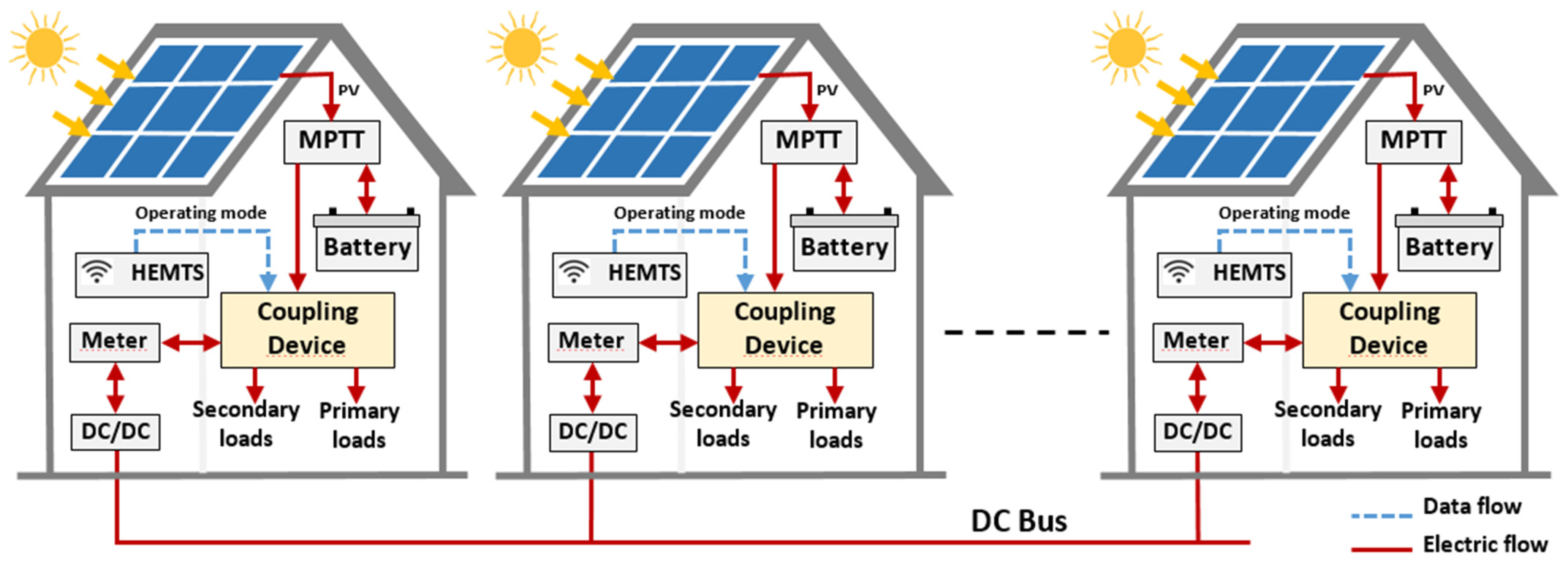
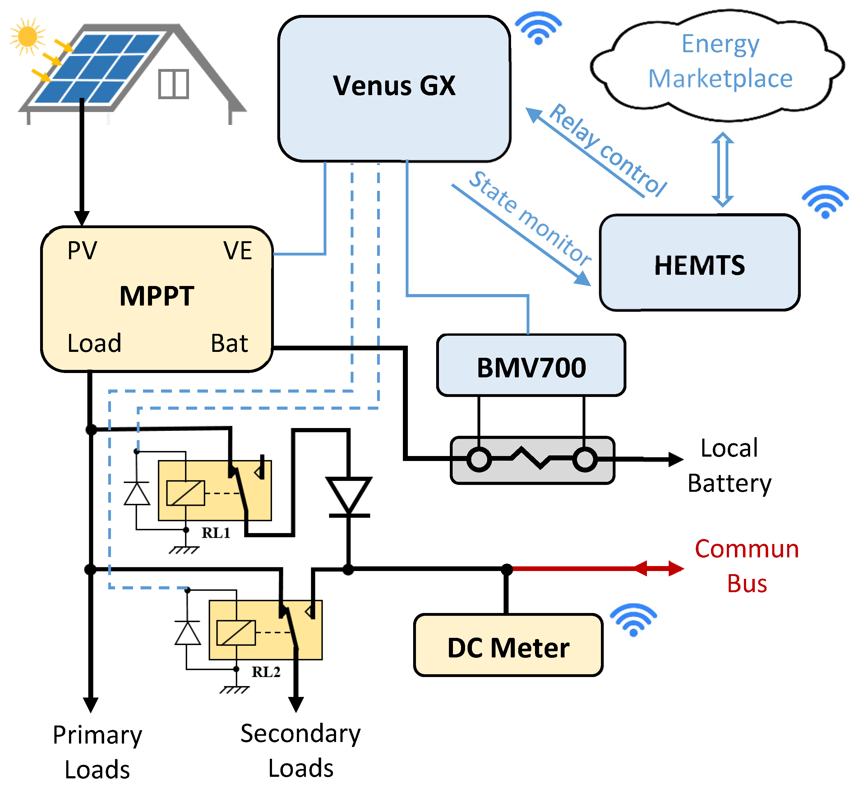
The proposed electrical architecture guarantees that the local resources such as local PV and batteries are used primarily to power household loads. Local energy is managed to always meet local primary (non-shiftable) loads. Any excess energy may be stored in a local battery or shared with community members. As shown in Figure 2, secondary (shiftable) loads can be powered by either household local resources or excess energy from a neighbor. To meet their energy needs and ensure their comfort, households use available shared energy from neighbors to power these shiftable loads. Thus, the proposed architecture considers secondary loads as community-shared loads.
Furthermore, the local battery is protected from over-usage as it is not directly connected to the common bus. It is always controlled by the Maximum Power Point Tracking (MPPT) module as in a standalone installation. By coupling the household from the MPPT load output, it provides a stable voltage at the bus coupling point. This also allows for the control of the total load and makes it possible to decouple from the bus when needed.
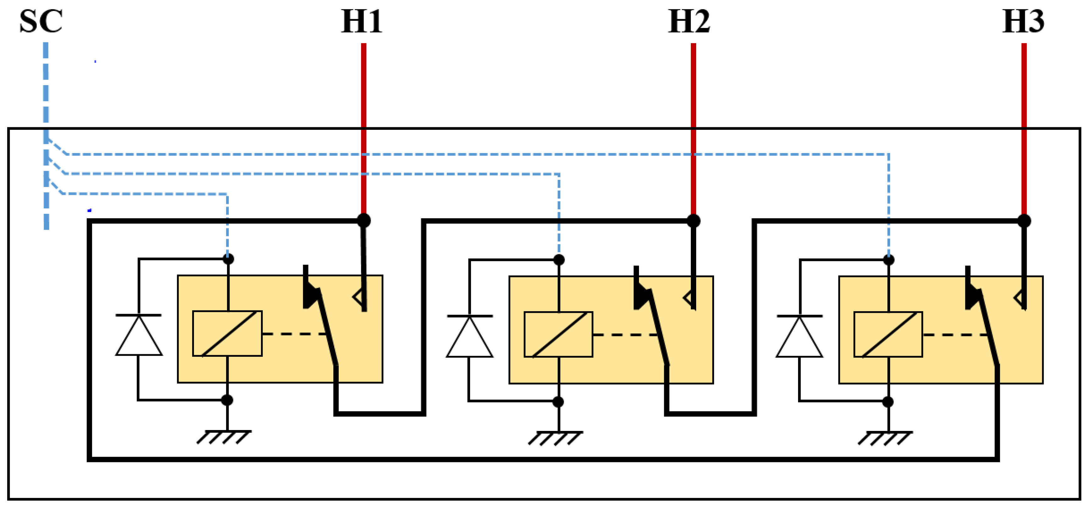
Hence, the architecture offers the possibility of switching between three operating modes that are fully controlled by the HEMTS using two relays.
Autonomous Mode: (RL1 OFF; RL2 OFF): Isolates the home installation from the microgrid.
Prosumer Mode (RL1 ON; RL2 OFF): Connects the house on the microgrid bus to inject electrical energy in case of a surplus. A Diode (D) guarantees that power flows only from the household to the community bus.
Consumer Mode (RL1 OFF; RL2 ON): Connects the household on the microgrid bus to purchase electrical energy in case of need. In this case, secondary load demand may be satisfied from a neighbor prosumer.
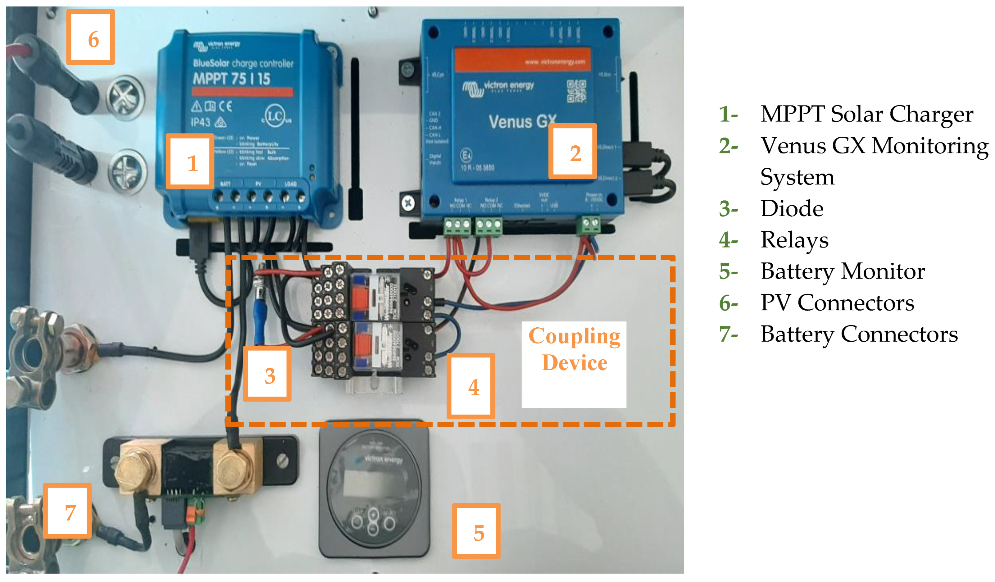
In order to enable this multimode operation, a coupling device must be added to the typical household PV installation as shown in Figure 3. This coupling device is controlled by the HEMTS depending on the household operation mode.
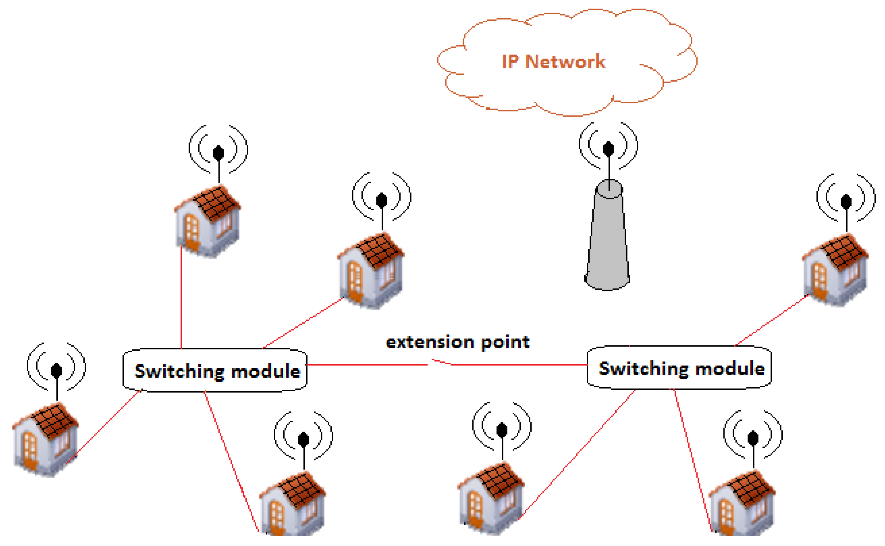
Moreover, in order to ensure P2P transactions, a smart metering device is used to measure ingoing and outgoing power flows. The measurement data are used to process energy payments. With our proposed architecture, two methods of payment may be envisaged. In the first case, all peers share a single electric circuit (the common bus) to exchange power flows. Smart metering data are used by the marketplace to track operations and establish participant earnings and dues. In this case, purchases are periodically post-paid. In the second case, a central switching module is added to the LVDC infrastructure (see Figure 4). The role of this module is to establish a dedicated electric circuit between a prosumer and a consumer. All houses of the microgrid are connected to the central switching module. For example, if there is an electrical exchange between house 1 and house 2, only switch 1–2 will be closed, while the other switches remain open. In this star topology, the outgoing energy measured at the prosumer’s smart meter is expected to be equal to the incoming energy measured at the consumer’s smart meter. Peers involved in exchange may choose between the post-payment or the pre-payment mode. In this second payment method, peers may simply make a deal by alternating the use of the excess energy from the two household installations. By using a dedicated electric circuit for each electric exchange, the reliability of the microgrid may be improved.
In the proposed star topology, the microgrid architecture is based on an LVDC electric network. It is an easily extensible architecture. A Wireless NAN enables household smart meters to access the Internet by using a common wireless access point as detailed in Figure 5.

3.2. Blockchain-Based Control in Rural Context

The application of the Blockchain-based exchanges’ place in a rural environment is seldom considered by the research community. In this section, we give particular attention to the application of Blockchain in a rural environment context, covering aspects ranging from the architecture to payments and automation.
  • Blockchain architecture in rural communities
Blockchain use requires a network for transaction performance, validation, achieving consensus among peers, and updating the ledger. However, in the context of rural communities, internet-based communication may not be available. In such cases, a local network can be established among participating peers.
  • Payment
To adapt the exchange place to a rural context, we utilize an account unit as the price for exchanged energy instead of cryptocurrency, making it more suitable for off-grid low-income households. Specifically, we build upon the Quorum-permissioned Blockchain platform [57], eliminating the need for rewarding peers for the mining process. Consequently, households participating in the microgrid installation are initially provided with a sum of unit accounts. These unit accounts serve as the means for paying and trading energy. Each user can specify their preferred energy price, such as 1 kWh = 2 account units.
  • Automation
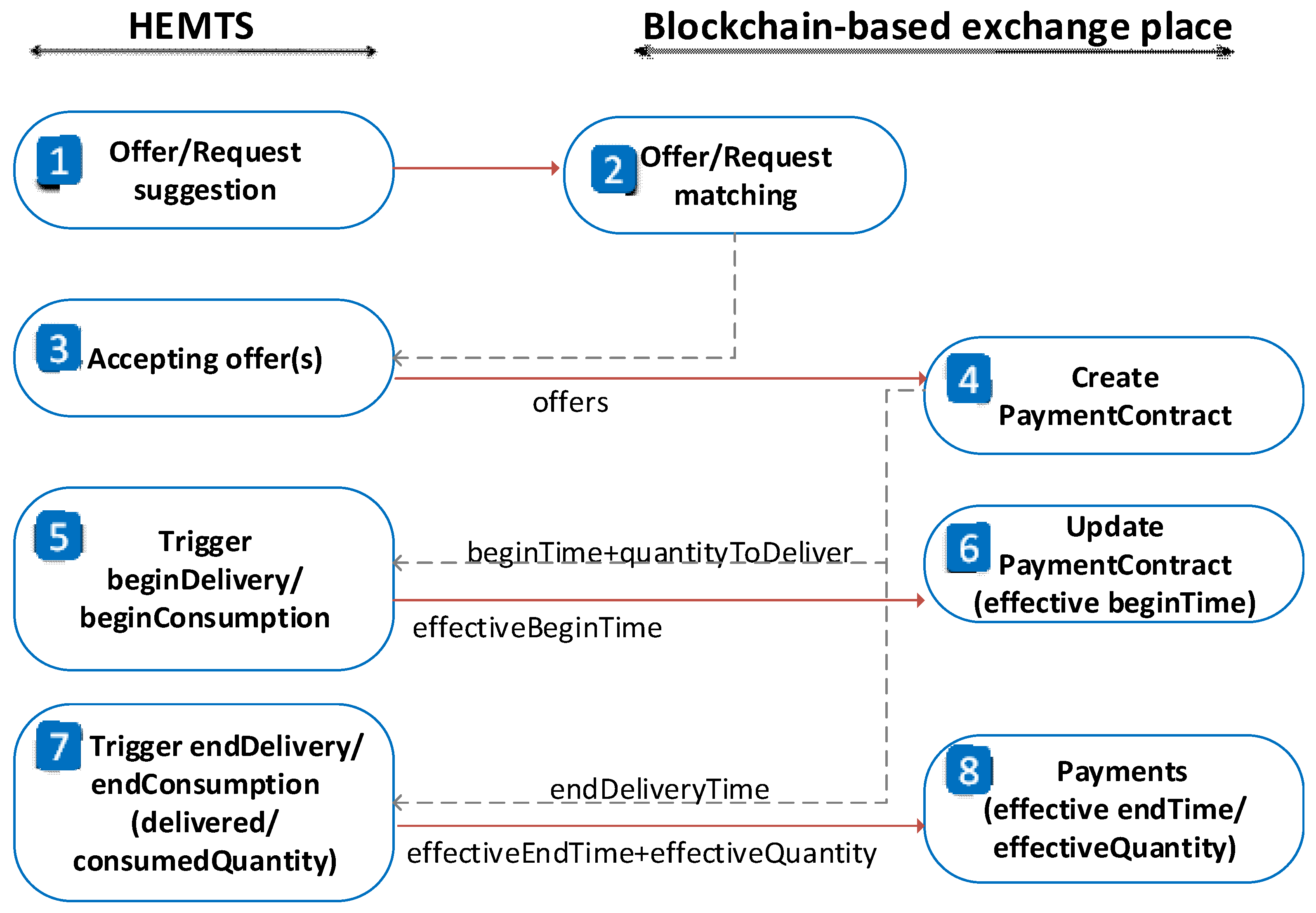
Considering the rural environment, automation plays a crucial role in reducing barriers in the community to adapt such a system. To achieve this, the Home Energy Management and Trading System (HEMTS) and the generic exchange place are integrated to automate all the processes, as depicted in Figure 6.
By providing the consumption and production estimation, the HEMTS posts offers, in the case of energy excess or requests, in the case of energy scarcity (1). The exchange place then matches these offers and requests notifying the HEMTS of the available offers (2). Once the HEMTS automatically accepts the offer(s) (3), a payment contract is created on the Blockchain (4). This contract stores all the necessary data for payment settlement, including the begin and end time of delivery, the quantity to be delivered, and the price per Watt-hour. These data are subsequently utilized by the HEMTS to trigger the energy exchange process.
When the beginning delivery start time is reached, the HEMTS of the prosumer initiates the delivery process, while the HEMTS of the consumer initiates the consumption process (5) and (6). The end of delivery is triggered either when the required quantity has been delivered or when the end time of delivery is reached (7). The actual delivered and consumed energies, as measured by smart meters, are recorded in the Blockchain. Payments are adjusted based on the minimum value between the delivered and consumed energies.

3.3. Home Energy Management and Trading System

The control of the HEMTS multimode operation is described in the state diagram shown in Figure 7. In this diagram, each operation mode is associated with a state, and transitions are triggered by signals from the battery control and the energy exchange control. As explained in Section 3.2, the timing signals and energy quantities are specified in the smart contract within the exchange marketplace after successful matching of trading operations. The beginDelivery time and beginConsumption indicate the date of the exchange. The endDelivery condition is satisfied when the quantity to be delivered is reached or the delivery end time expires. Similarly, the endConsumption condition depends on the quantity to be consumed and the consumption end time.
In our work, we propose a new hybrid P2P exchange control strategy. It is based on both trigger-only and amount-based control strategies [46]. Exchanges are triggered depending on the battery SOC levels and an estimation of the energy demand. As shown in the flowchart in Figure 8, the HEMTS continuously monitors the SOC level of the battery. In autonomous mode (refer to Figure 8a), if the measured SOC exceeds a pre-set trigger value SOCp or falls below a pre-set trigger SOCc, both defined by the user, the HEMTS calculates an estimation of energy excess Esh or energy request Erq, respectively. Based on the calculated quantity, an offer is posted if Esh exceeds the offer threshold Oth, or a request is posted if Erq exceeds the request threshold Rth on the exchange place.
In prosumer mode (refer to Figure 8b), if the measured SOC value falls below a minimum value SOCpmin, the HEMTS returns to autonomous mode to preserve the battery. Similarly, in consumer mode (refer to Figure 8c), if the measured SOC value exceeds a maximum value SOCcmax, the HEMTS returns to autonomous mode.
Then, the exchange place suggests the available offers, in case of posting a request and send notification of available requests, in case of posting an offer.
In order to implement this control approach, we have formulated the equations needed to calculate the required values and estimations, which are detailed below.
  • The battery state of charge:
The battery state of charge at time t (SOCt) is estimated based on its SOC at time t − 1 (SOC(t−1)), using the current (Ibt) and voltage (Vbt) values in the time interval Δt between t − 1 and t as well as the total battery capacity (Etbat) [58]. We note that t represents the time step of the microgrid system operation. In our case, we considered t to be one hour; consequently, t ∈ [1; 2; …24].
The total battery capacity Etbat is typically expressed in Ampere-hours (Ah). If we assume that Icbat is the battery capacity in Ah and Vbat is the battery voltage, the total battery energy (Etbat) can be expressed in Watt-hours (Wh) as follows:
E t b a t = V b a t × I c b a t
Then, SOC(t) is expressed as follows:
S O C ( t ) = S O C ( t 1 ) + V b t I b t × t E t b a t
  • The total energy demand
In the case of autonomous mode, the total energy demand for each time slot is computed based on the power demand and usage periods of each appliance, as shown in Equation (3):
E t d ( t ) = E p d ( t ) + E s d ( t ) = i = 1 N p P p i × τ i   ( t ) + i = 1 N s P s i × τ i   ( t )
E p d ( t )   a n d   E s d ( t ) are primary and secondary loads energy demands at time slot t.
N p N s is the number of primary (secondary) loads.
P p i   a n d   P s i are power demand of primary (secondary) appliance i.
τ i is the duration of the operation of appliance i at time slot t.
  • The estimation of the energy excess and energy request
The estimation of energy excess quantity is performed each time the battery SOC exceeds the pre-set trigger value SOCp (the Prosumer Start Trigger). To estimate the energy excess quantity Esh(t), the energy stored in the battery at time t, Ebat(t) is computed based on its SOC(t).
E s h ( t ) = S O C ( t ) × E t b a t E t d ( t )
In the same manner, an estimation of energy-request quantity is performed each time the battery SOC falls below the pre-set trigger value SOCc (the Consumer Start Trigger).
In the case of matching, the total energy demand for each time slot is updated to consider the amount of energy that will be exchanged, as shown in Equation (5):
E t d ( t ) = E p d ( t ) + E s d ( t ) + E s h ( t )
E s h ( t ) is the quantity of energy that will be exchanged at time slot t. E s h ( t ) is positive for the supplier due to the overload supplied to the peer’s shared load and negative for the requester since the shared load is powered by the matched supplier peer.
  • The efficiency of energy conversion
The efficiency of DC-coupled SHS depends on the efficiency of each equipment. When PV production exceeds power demand, the SHS efficiency is expressed by Equation (6). Referring to technical equipment specifications, η S H S D is about 81%.
η S H S D = η P V × η r e g × η c a b
η P V is the PV panel efficiency.
η r e g   is the regulator efficiency.
η c a b   is cables efficiency.
When loads are powered from battery, the SHS efficiency is expressed by Equation (7). If we consider that the discharge efficiency of the battery is 80%, the SHS efficiency falls to about 65%.
η S H S I N D = η b a t × η S H S D
η b a t is battery discharge efficiency
Since the shared loads are powered by the excess PV production, we use Equation (5) to estimate the efficiency of energy conversion in case of exchange. However, we must also consider additional losses due to coupling to the microgrid and transport to the neighboring house.
After defining the electric architecture and the exchange process, a small scale testbed is implemented and presented in the following section.

4. Experimental Validation

4.1. The Microgrid Testbed Setup

The microgrid testbed utilizes a set of Wi-Fi IoT modules to oversee the remote supervision of each SHS (Solar Home System), control loads, and manage PV power production. With the exception of the Venus GX control panel and the HEMTS, all Wi-Fi modules are based on the ESP32 Wi-Fi node (Espressif Systems, Shanghai, China). To ensure synchronization of scenario operations, all smart modules in the testbed rely on the same Internet time server. Figure 9 illustrates the household architecture: the SHS incorporates a Victron MPPT (Maximum Power Point Tracker) to interconnect the solar panel, battery, and loads.
The battery’s state of charge (SOC) is monitored using a Victron BMV700 module sourced from the Netherlands. The SHS operation is supervised by a control panel called Venus GX. The Venus GX gathers electrical data from the MPPT and the BMV700 through a Ve.direct cable connection. The HEMTS can access all electrical data and SOC measurements from the control panel either through a local Wi-Fi connection or a dedicated web portal.
The power relays RL1 and RL2 and the diode of the coupling device are capable of supporting a DC current of up to 10A. They are electrically isolated from the relays of the Venus control panel, specifically RL1C and RL2C (refer to Figure 10).
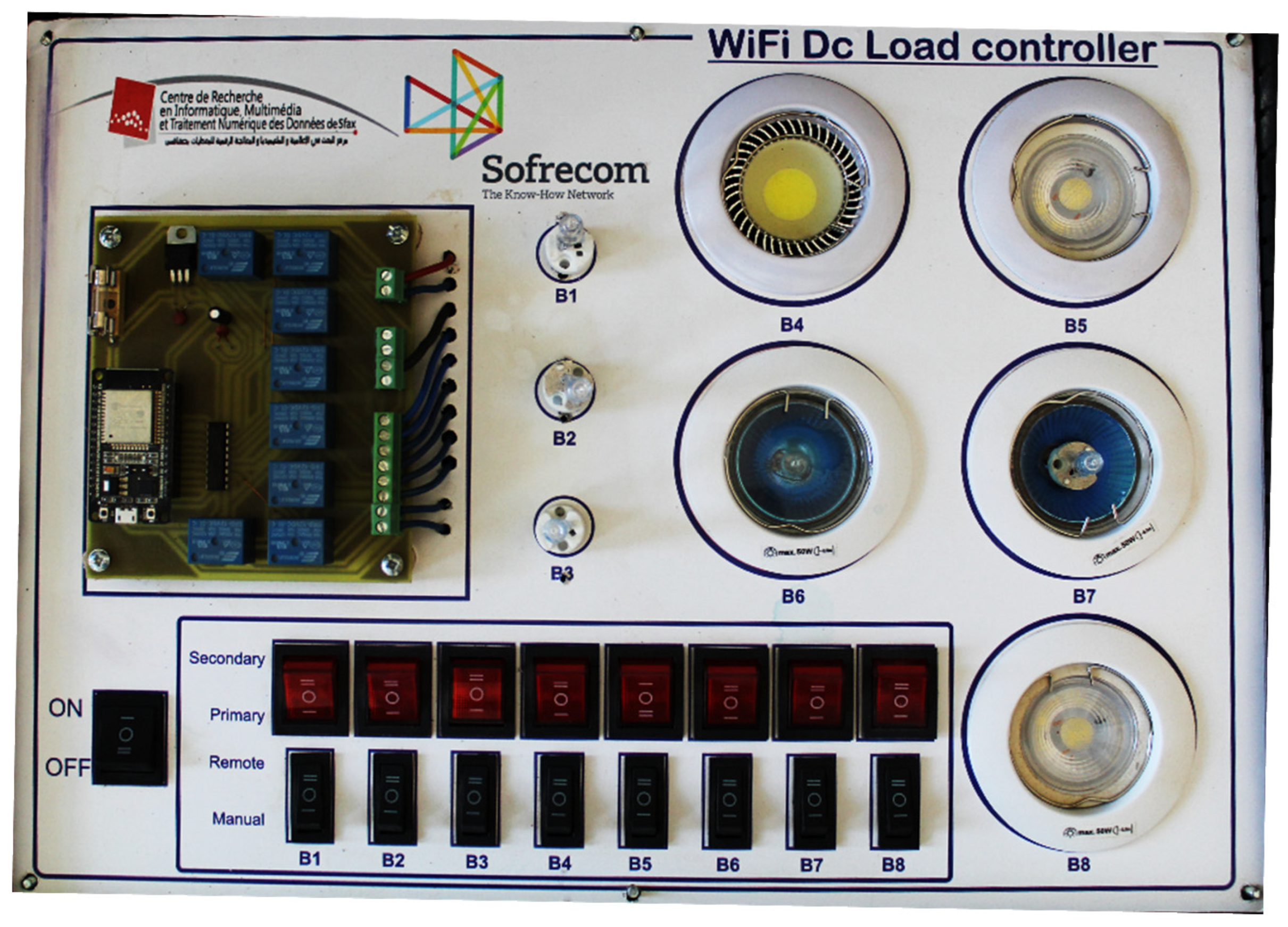
The loads of each household are simulated using controllable DC lamps (refer to Figure 11). The control card of the system is built around a Wi-Fi MCU module that drives a set of eight relays. This setup allows for the replication of various daily load curve scenarios. Each lamp can be configured as either a primary or a secondary load. The power demand and operating time of the load system are programmable. The load schedule is transmitted remotely through Wi-Fi.
A set of projectors is employed to provide illumination for household PV panels. The power of the projectors is adjusted using a BAT 16 triac-based control card. The power control settings of the projectors are programmable remotely through a Wi-Fi module in order to replicate a realistic daily, hourly PV production profile (refer to Figure 12).
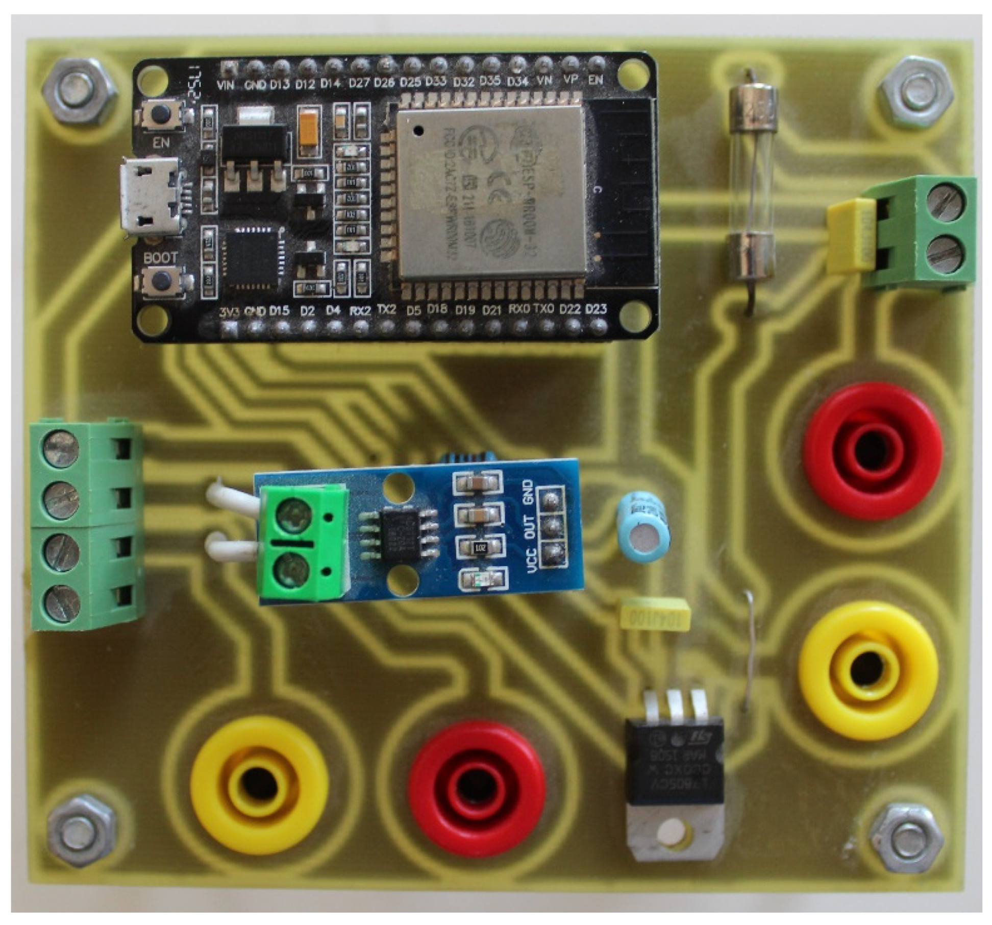
The exchanged power flows are measured using a Wi-Fi-enabled DC power meter. These measurements are continuously monitored in real time by the HEMTS in order to switch to autonomous mode once the amount of delivered or consumed energy is achieved (refer to Figure 13).
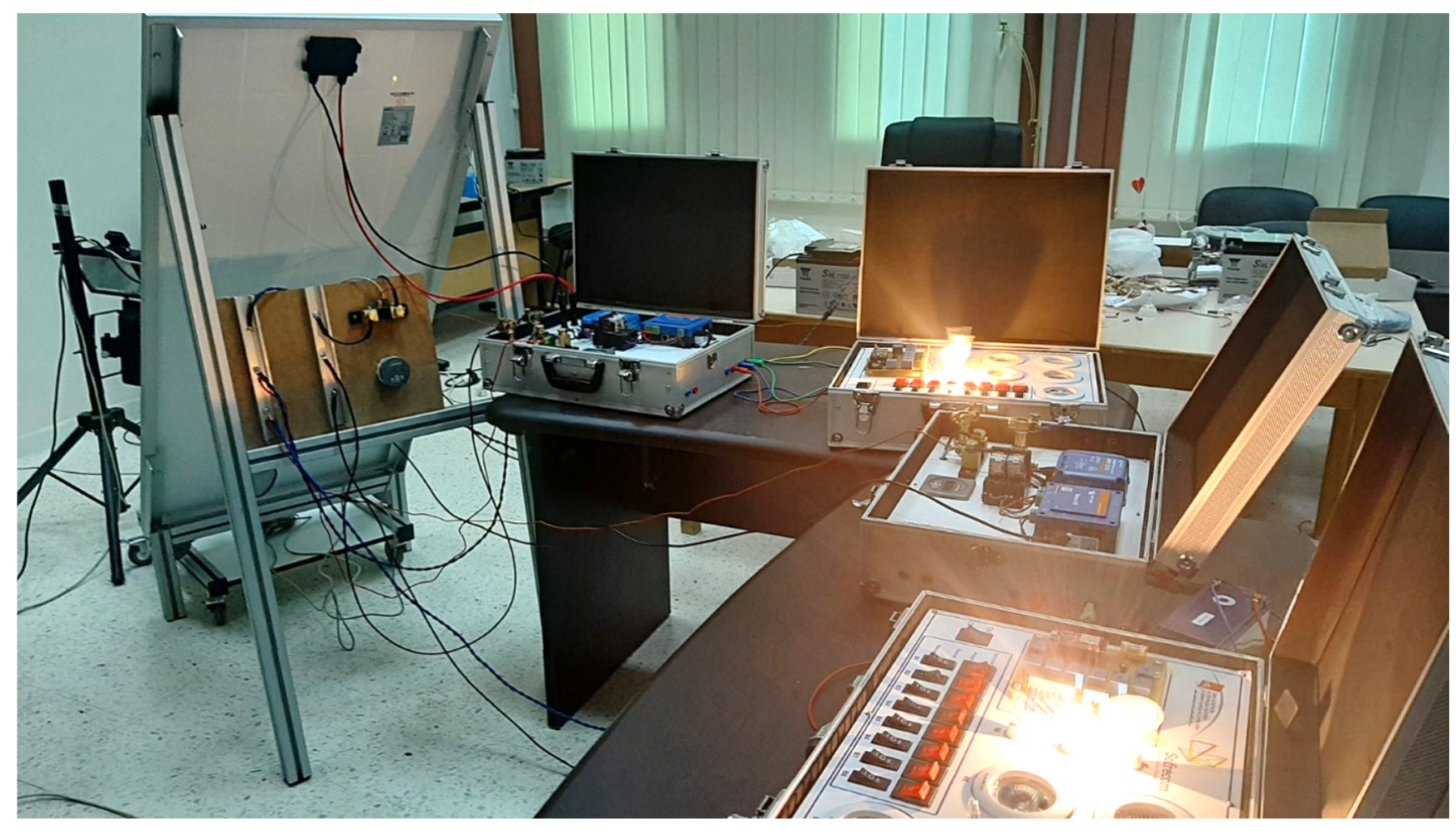
Figure 14 depicts a photo of our microgrid testbed, showcasing the various modules described earlier.

4.2. Experimental Results

Daily household load profiles are generated using a stochastic approach with the LoadProGen simulation Matlab GUI [33]. In this bottom-up approach, the power demand and the daily operating period and duration of each appliance are set to generate realistic load profiles.
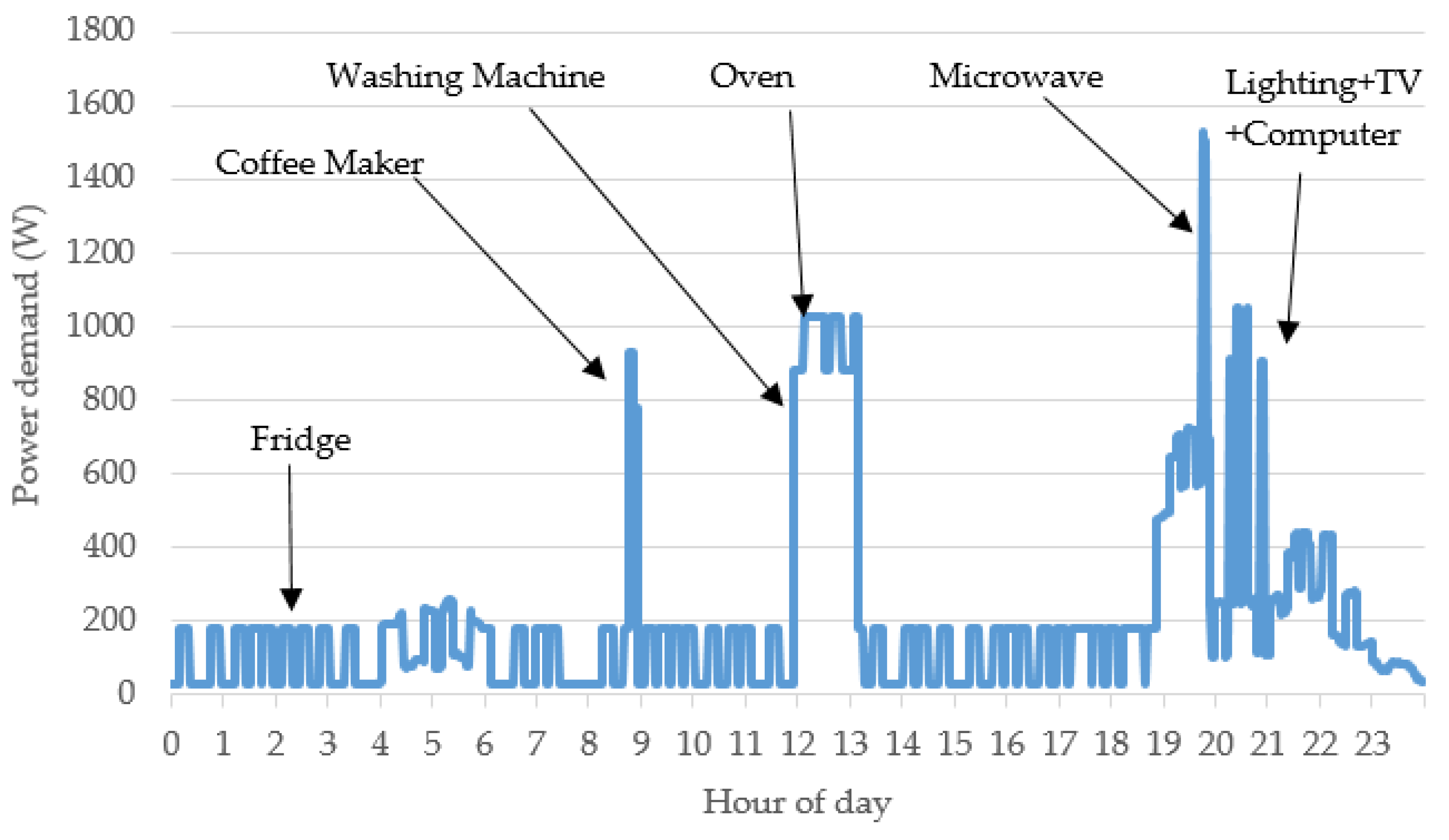
Household appliances are chosen considering the off-grid context and efficient DC appliances [36]. Figure 15 illustrates an example of the resulting one-minute sampled power demand curve. The power data output is used to compute the hourly energy consumption of the household resulting from different inhabitants’ activities, such as lighting and cooking.
P2P exchange scenarios have been developed to showcase the complementarity between houses. These scenarios address two key aspects related to unused PV production for a supplier house and peak shaving for a requester house. To demonstrate the enhanced performance of each SHS due to P2P energy exchange, we conducted two sets of tests. Initially, we operated the two houses independently in standalone mode (equivalent to autonomous mode). Subsequently, we allowed each HEMTS to automatically manage the hourly operating mode of each house in order to illustrate the improved performance.
To meet the laboratory conditions, the levels of the daily load curves are initially scaled using a set of DC lamps, and each hour is further scaled down to five minutes. The experiment duration of each scenario is two hours.
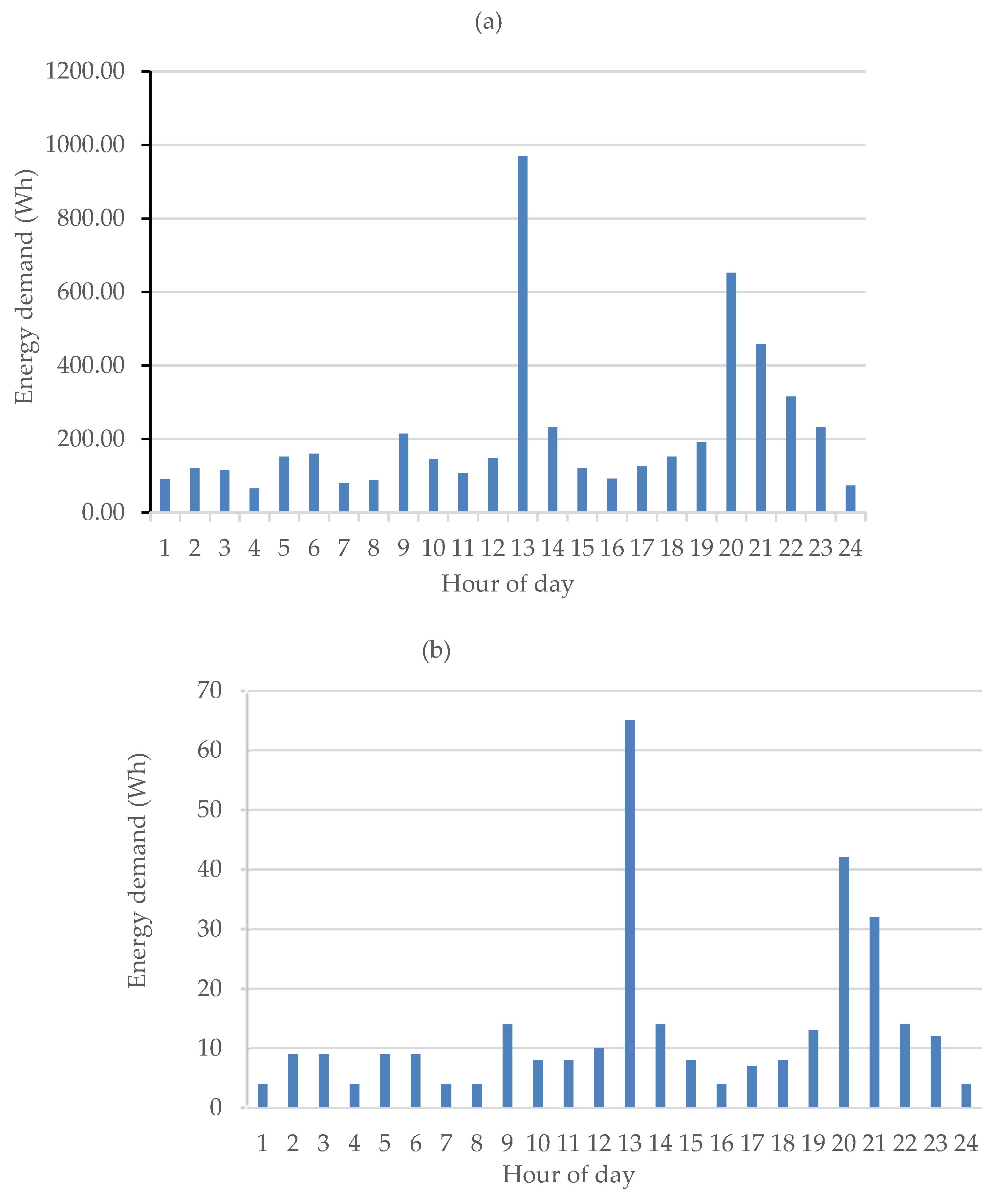
Figure 16 illustrates the hourly load profile for the supplier, while Figure 17 displays the hourly load profile for the requester. These two load curves exhibit distinct profiles, which enable the possibility of energy exchange. Table 1 provides detailed electrical specifications for each house in the testbed. Discharge–charge cycles are executed, and experimental results are adjusted based on the scaled total daily demands, as well as the sizes of the PV panels and batteries in the testbed.
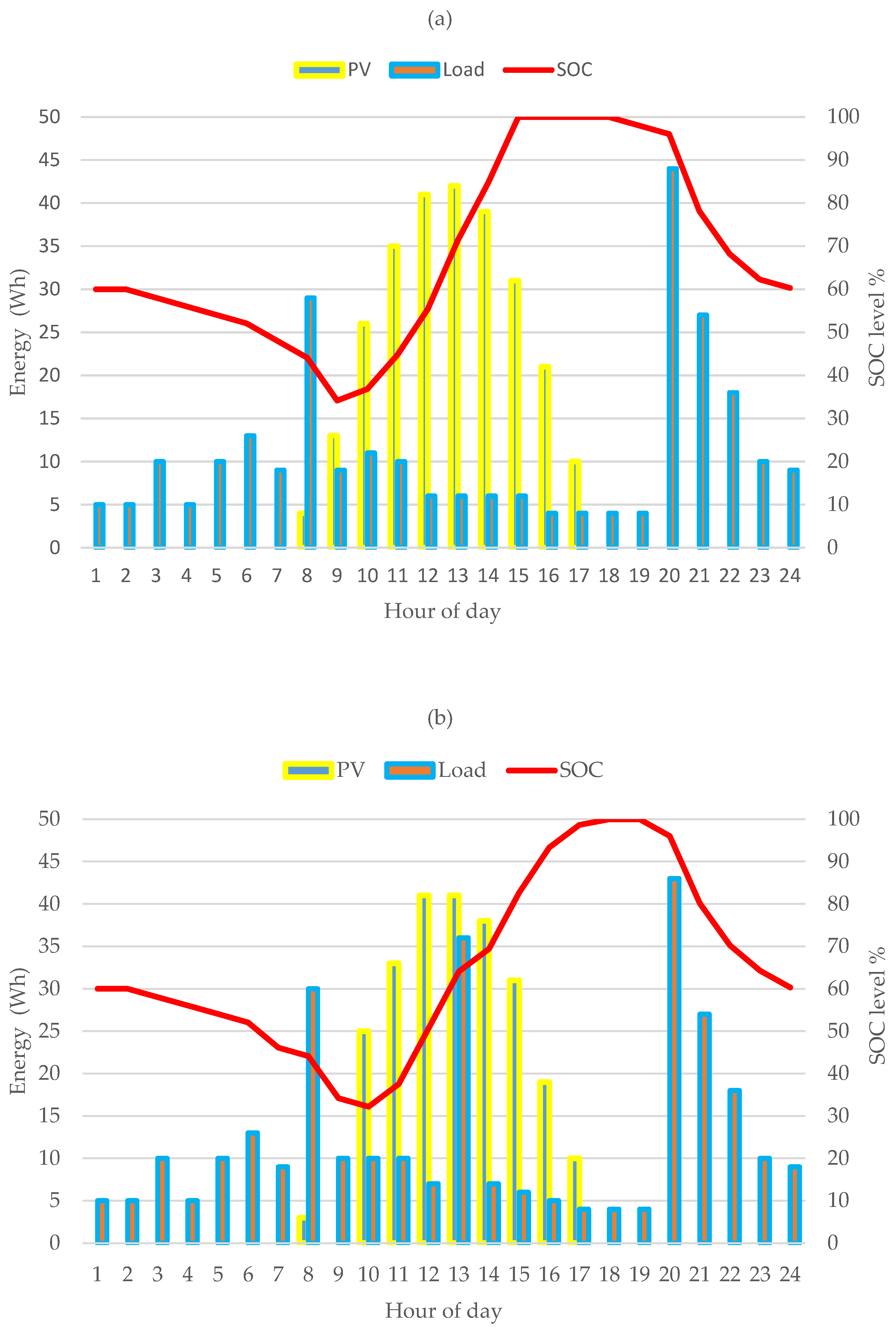
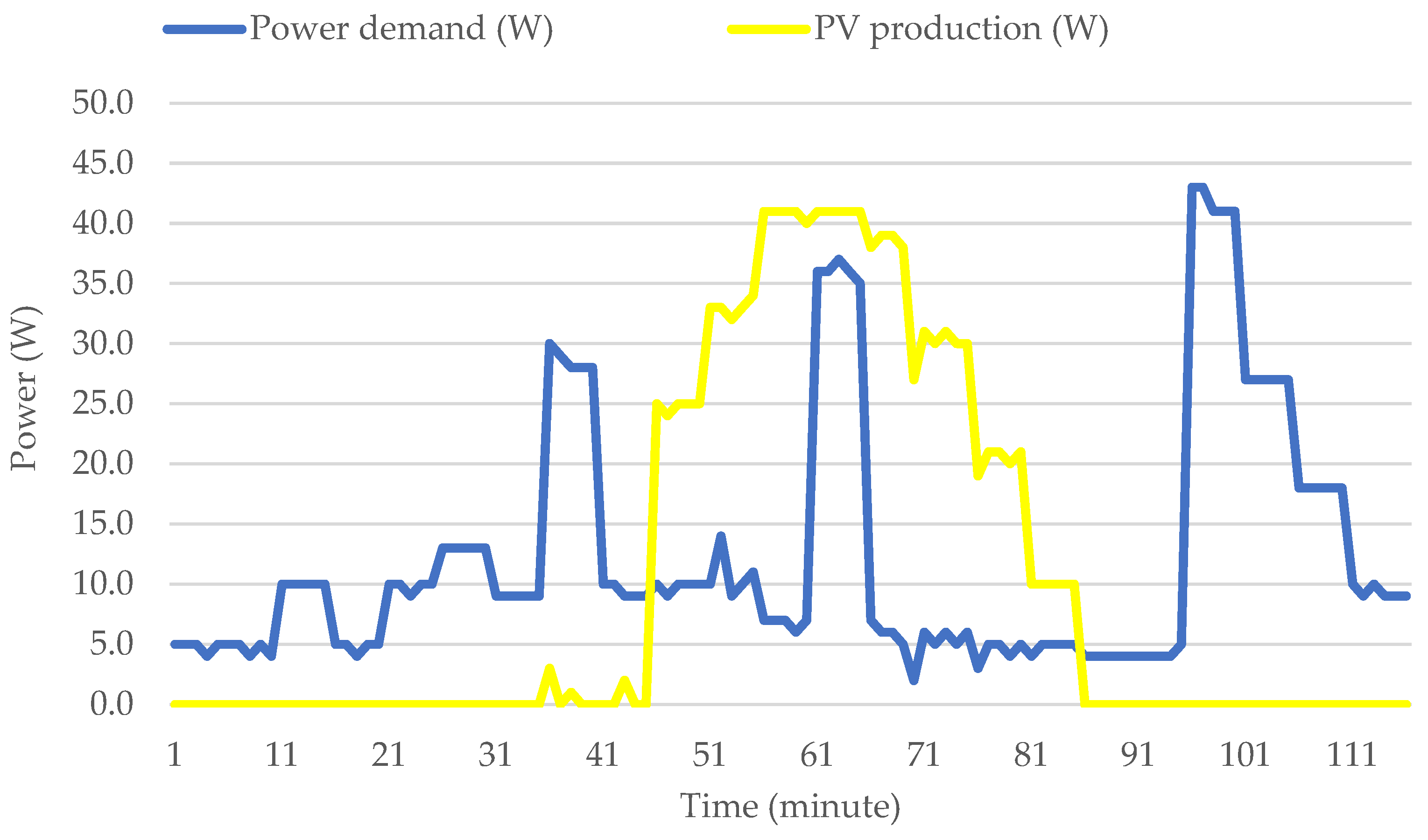
The following results present power measurements sampled at one-minute intervals to illustrate the detailed operation for each SHS. Figure 18 shows supplier power curves. During nighttime, power is consumed from the battery, which is discharged to a low level of 34% by early morning. During the daytime, when PV production exceeds power demand, loads are supplied from PV, and the surplus is used to charge the battery. After completing the charge cycle, the surplus PV production is lost.
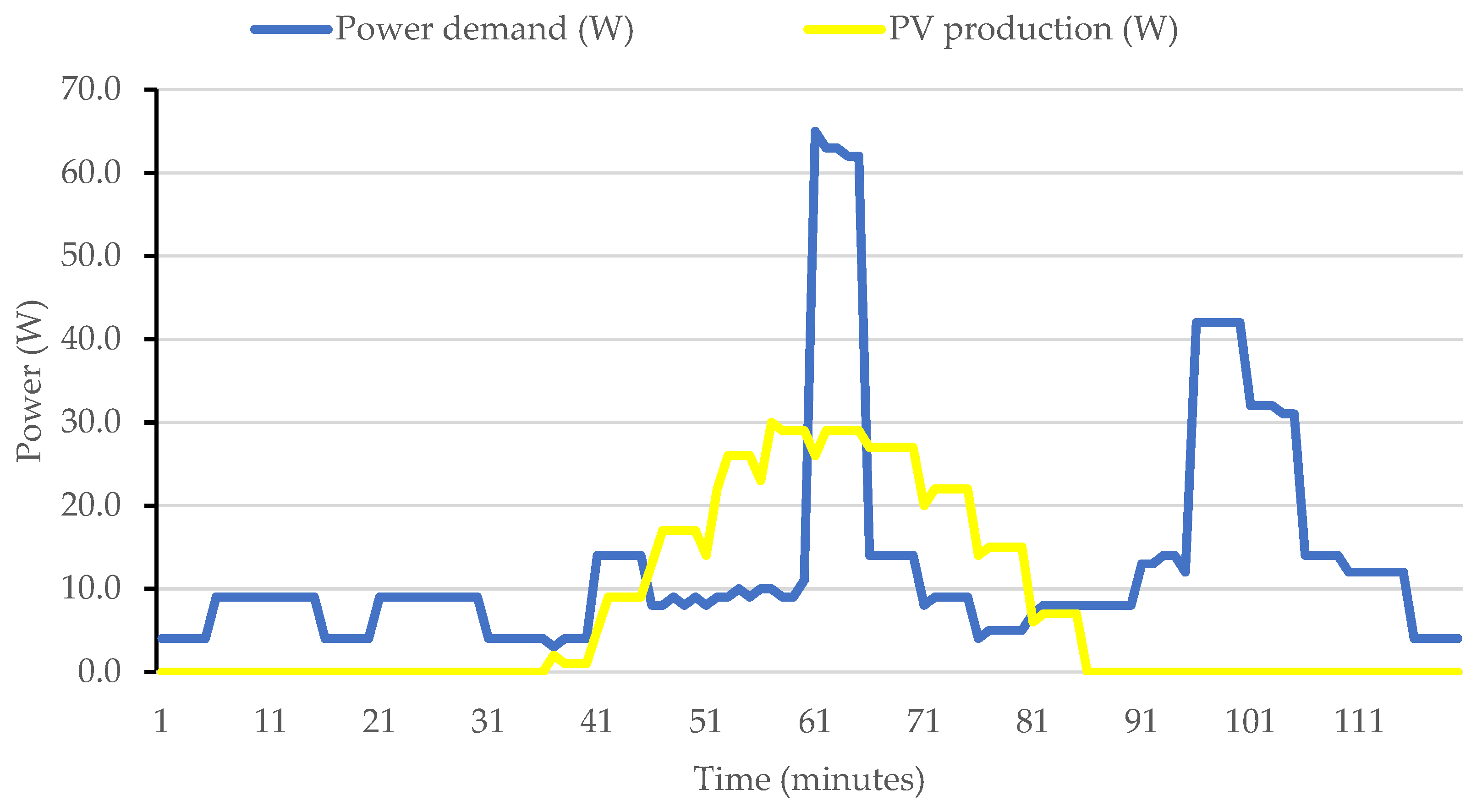
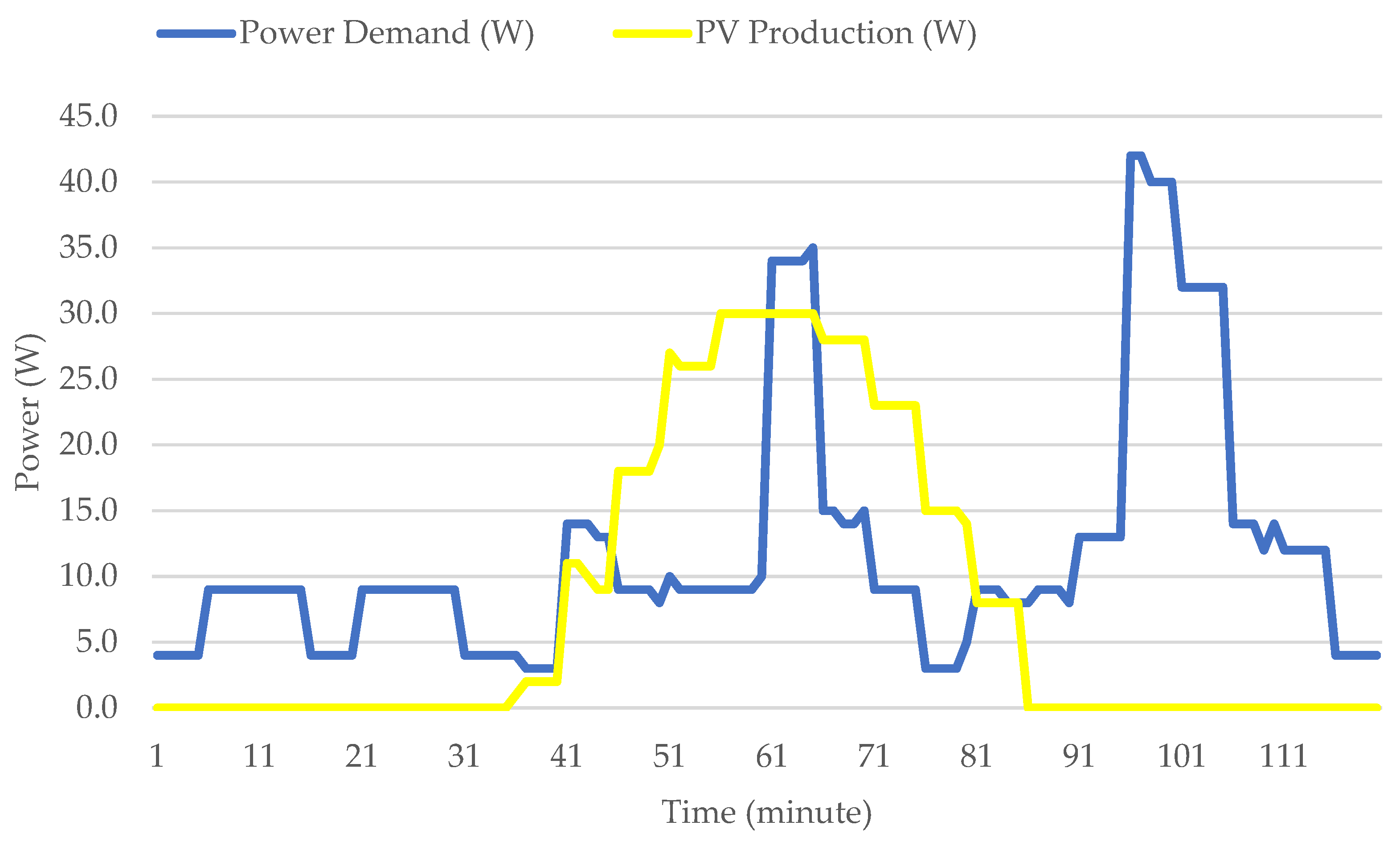
Figure 19 shows the requester power curves sampled at one-minute intervals in standalone operation mode. The demand peak of about 60 W observed during the daytime exceeds PV production and induces an unexpected discharge cycle of the battery during this time of day.
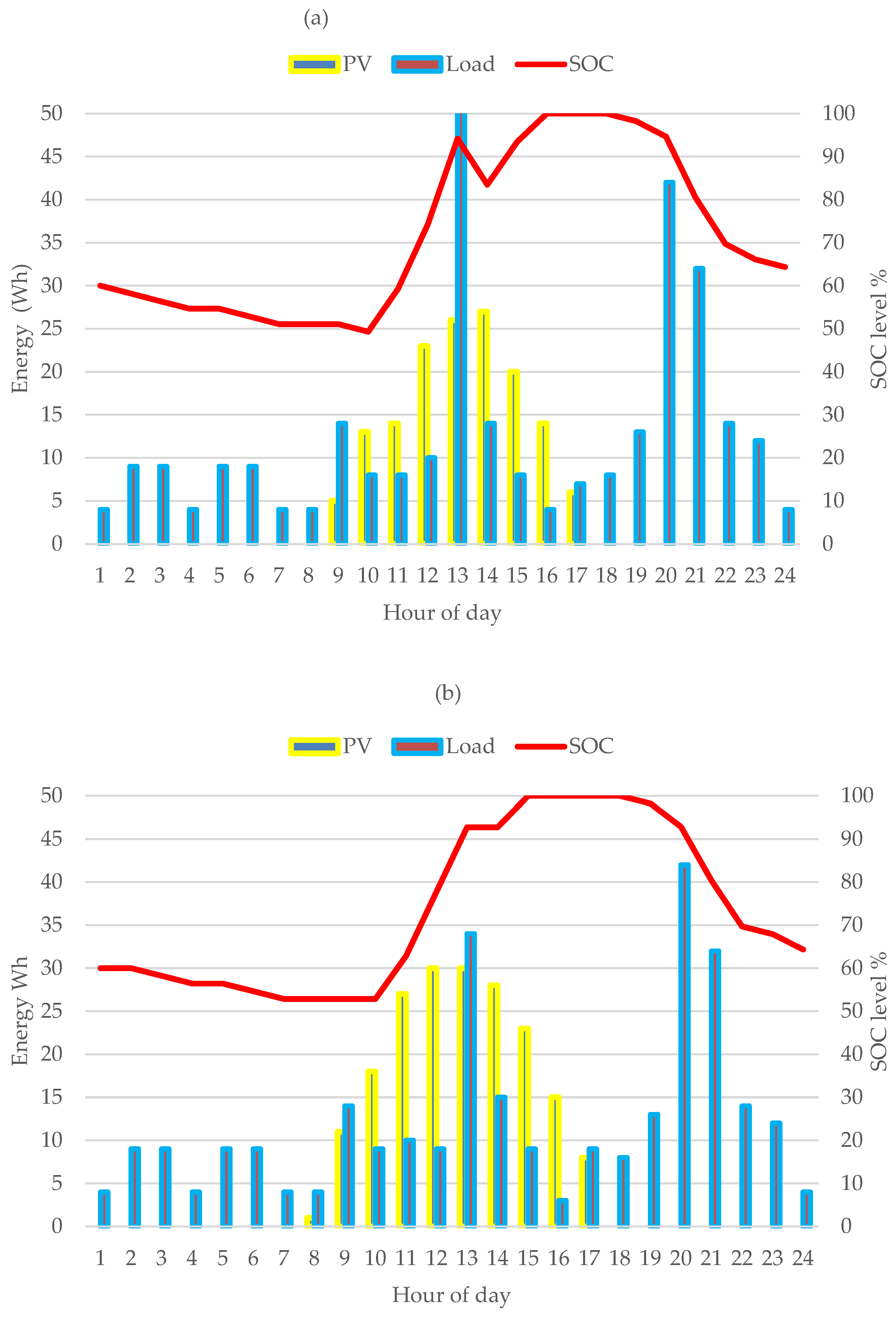
To illustrate the results of HEMTS control strategy, energy curves are presented at the microgrid scheduling time step. Hourly energy curves are shown for the two households. The curves for the supplier are depicted in Figure 20 and Figure 21, while those for the requester are shown in Figure 22 and Figure 23. The state of charge (SOC) of the battery is estimated using Equation (2).
Figure 21 presents the supplier power curves measured at one-minute intervals in exchange mode operation. During the daytime, the electricity load added due to exchange operation causes the peak power demand. The surplus PV production allows for both the full charge of the battery and powering the neighbor’s shared load.
On the other hand, as expected for the requester house, when the demand exceeds the PV production, as observed at hour 13 (see Figure 22a), energy is drawn from the battery to meet the demand. The peak demand at hour 13 is expected to result in a partial discharge of the battery, increasing the number of discharge–charge cycles per day. However, it is crucial to limit the number of cycles to one per day in order to extend the lifespan of the battery.
Figure 20b and Figure 22b display the energy curves for households when managed by HEMTS. During periods of high renewable energy production, only the surplus energy beyond the local demand is offered for sale, ensuring that the battery charge remains undisturbed (refer to Figure 20b). At hour 13, the supplier’s HEMTS strategically plans an energy offer taking into account the peak PV production and the low local demand. Similarly, the requester’s HEMTS plans an energy demand to effectively shave the peak and prevent any partial discharge of the battery (refer to Figure 22b).
Before posting offers/requests to the marketplace, the supplier’s HEMTS ensures that the SOC levels will not be adversely affected by executing the energy offer (refer to Figure 20). Similarly, the requester predicts the impact of the purchase operation on the variation in the SOC levels of their local battery (see Figure 22).
The offer/request is matched at the marketplace level, and the P2P energy exchange is executed by the supplier HEMTS which switches to prosumer mode at hour 13, and by the requester HEMTS which switches to consumer mode at the same hour.
After executing the P2P exchange scenario, we observed that the supplier’s battery was able to achieve its full charge at hour 18, effectively minimizing the loss of surplus PV production. On the consumer side, the energy purchase successfully shaved the peak caused by the high demand of the consuming appliance. This action limited the discharge current and eliminated the need for partial battery discharge.
Figure 23 presents the requester power curves measured at one-minute intervals in exchange mode operation. During the daytime, the electricity consumed from the community reduces the peak power demand. This reduces the power consumed from the battery when demand exceeds the PV production.
Household energy performance indicators are proposed to evaluate daily household participation inside the PV community. The same indicators may be adapted for other time periods. See Equations (8) and (9).
In Equation (7), the energy-sharing performance indicator E s h p measures the amount of PV production shared. It is the rate of daily energy shared to the total daily PV energy produced. It ranges between 0 and 1. Greater values indicate better performance.
E s h p ( % ) = i = 1 24 E s h i i = 1 24 E p v
In Equation (8), the energy-request performance indicator E r e q p , measures the amount of needed energy. It is the rate of daily energy request from the total energy demand. It ranges between 0 and 1. Lower values indicate better performance.
E r e q p ( % ) = i = 1 24 E r q i E t d
Figure 24 illustrates both the shared PV energy at prosumer side (Figure 24a) and the community-shared load at the consumer side (Figure 24b). In Figure 24a, the PV shared energy is indicated in green while in Figure 24b, the community-shared load is indicated in red. Energy performance indicators of each house are shown in Table 2. The energy-sharing performance indicator, E s h p , is equal to 16%, indicating the amount of reduced PV production losses at the prosumer side. Meanwhile, the value of 11% for the energy-request performance indicator, E r e q p , indicates the amount of energy purchased to shave the peak at the consumer side.

5. Conclusions

The United Nations Sustainable Development Goal (SDG) 7 aims to ensure access to affordable, reliable, sustainable, and modern energy for all by 2030. However, the expansion of solar energy solutions like the off-grid rural PV depends on the local government’s policy. Since the majority of investment is foreign, the adoption of off-grid solar systems at affordable prices is often dependent on the liberalization of the national energy sector and lower equipment costs. Efforts still need to be made to address other barriers related to the market for off-grid products and services that can serve as a basis for economic growth and development, and to propose alternatives to existing prepaid metering systems and pay-as-you-go financing models [59,60].
Through this work, we aimed to contribute to the adoption of solar solutions and innovative services adapted to the rural context. The proposed fully distributed architecture has been designed from the user perspective, taking into account the profile of the end user and making it easy for solar installers to operate. Indeed, it was designed to extend existing solar home systems by adding a microgrid coupling device that interfaces the SHS with the microgrid bus. This advantage allows the utilization of existing hardware for the proliferation of swarm electrification solutions.
In order to leave the choice to the end user, the HEMTS system has been designed to keep full control over its own installation. The user defines the schedules and the rules to ensure efficient and profitable energy exchange. Two sockets are available in the household to connect local loads or community-shared loads. Energy is managed on the demand side to shave peak demand and preserve the battery, which is the most vulnerable component of the SHS.
Since power flows are scheduled following matched demands/offers, the microgrid power balance is always controlled. Microgrid stability is improved since households connect to the microgrid bus only after exchange bids are matched. Moreover, in the proposed star topology, households are connected through an energy switching device that provides a dedicated electricity circuit for power flows during exchange operations. However, this generates an added cost for the microgrid cabling infrastructure.
We have demonstrated that P2P energy exchanges through a Blockchain-controlled marketplace present an attractive solution capable of improving both security and trust among community members. Additionally, effective tracing of exchange operations allows for alternatives to the pay-as-you-go market model, as the SHS user may monetize the surplus PV production to help repay their SHS.
The HEMTS scheduling strategy has been evaluated by considering energy curves at one-hour intervals for the microgrid operating system and tracing power flow measurements at one-minute intervals. P2P exchange scenarios have been developed to illustrate the complementarity between households. These exchanges are controlled through a Blockchain marketplace, specifically designed for the rural context, using smart contracts that record exchange dates and energy quantities.
Experimental results demonstrate the effectiveness of the solution in achieving peak shaving, with 11% of the requester’s total demand being provided from the community. This leads to reduced discharge–charge cycles to one per day, preserving battery life. Furthermore, the solution achieves a significant reduction in prosumer’s production losses, amounting to 16% of the total PV production. Further scenarios can be considered to validate our energy-sharing approach.
The microgrid architecture has been designed for remote rural regions with high PV potential and limited or costly access to the grid. It has limitations for tropical regions, which may experience extreme conditions, such as several days of continuous rain. In these regions, the SHS battery capacity should be sized to ensure more than one day of autonomy, or a fuel backup generator should be shared at the community level. In this case, the use of the backup generator should be tracked for each member to fairly distribute its cost among all community members.
Finally, the proposed architecture needs to be assessed at the village scale to investigate its true potential for implementation as a solution for swarm electrification in rural regions.

Author Contributions

Conceptualization, K.T., A.G., S.B. and M.G.; methodology, K.T., A.G., S.B. and M.G.; software, K.T., A.G., S.B. and M.W.K.; validation, K.T., R.A., A.G., S.B. and M.W.K.; formal analysis, K.T., R.A., A.G., S.B. and M.W.K.; investigation, K.T., R.A., A.G. and S.B.; resources, K.T. and B.L.; data curation, K.T., R.A. and M.W.K.; writing—original draft preparation, K.T., R.A., A.G., S.B. and M.W.K.; writing—review and editing, K.T., R.A., A.G., S.B. and M.W.K.; visualization, K.T., R.A., A.G., S.B. and M.W.K.; supervision, K.T., B.L. and M.G.; project administration, K.T. and B.L.; funding acquisition, B.L. and M.G. All authors have read and agreed to the published version of the manuscript.

Funding

This work was funded by Orange Innovation as part of the Virtual Power Plant project carried out at Digital Research Center of Sfax in collaboration with Sofrecom Tunisia.

Data Availability Statement

Data not covered by confidentiality agreements will be made available upon request.

Conflicts of Interest

Authors declare that the research was conducted in the absence of any commercial or financial relationships that could be construed as a potential conflict of interest.

References

  1. United Nations Development Programme. Available online: https://www.undp.org/energy/our-work-areas/energy-access/access-electricity (accessed on 10 January 2024).
  2. IEA, Paris. 2022. Available online: https://www.iea.org/reports/africa-energy-outlook-2022 (accessed on 12 February 2024).
  3. Energy Sector Management Assistance Program. Mini Grids for Half a Billion People: Market Outlook and Handbook for Decision Makers; ESMAP Technical Report; 014/19; World Bank: Washington, DC, USA, 2019; Available online: https://openknowledge.worldbank.org/handle/ (accessed on 9 June 2021).
  4. Asian Development Bank. Handbook on Microgrids for Power Quality and Connectivity; Asian Development Bank: Manila, Philippines, 2020; Available online: https://www.adb.org/documents/handbook-microgrids-power-quality-connectivity (accessed on 24 May 2021).
  5. Zhou, X.; Guo, T.; Ma, Y. An overview on microgrid technology. In Proceedings of the 2015 IEEE International Conference on Mechatronics and Automation (ICMA), Beijing, China, 2–5 August 2015. [Google Scholar]
  6. Perez-DeLaMora, D.; Quiroz-Ibarra, J.E.; Fernandez-Anaya, G.; Hernandez-Martinez, E. Roadmap on community-based microgrids deployment: An extensive review. Energy Rep. 2021, 7, 2883–2898. [Google Scholar] [CrossRef]
  7. International Electrotechnical Commission (IEC) Report on LVDC Electricity for the 21st Century. 2017. Available online: https://www.iec.ch/basecamp/lvdc-electricity-21st-century (accessed on 13 July 2021).
  8. IEC TS 62257-1:2015 | IEC Webstore | Rural Electrification Solar Power LVDC. Available online: https://webstore.iec.ch/publication/23502 (accessed on 21 May 2024).
  9. Decuir, J.; Michael, P. Draft IEEE standard for DC microgrids for rural and remote electricity access applications. In Proceedings of the IEEE Conference on Technologies for Sustainability (SusTech), Phoenix, AZ, USA, 12–14 November 2017; pp. 1–5. [Google Scholar] [CrossRef]
  10. Groh, S.; Philipp, D.; Lasch, B.E.; Kirchhoff, H. Swarm electrification—Suggesting a paradigm change through building microgrids bottom-up. In Proceedings of the 3rd International Conference on the Developments in Renewable Energy Technology (ICDRET), Dhaka, Bangladesh, 29–31 May 2014; pp. 1–2. [Google Scholar] [CrossRef]
  11. Chowdhury, S.A.; Hasan, A.M.; Hasan, A.M.; Kirchhoff, H.; Groh, S. Shahriar Ahmed Chowdhury. In Solar DC Grids for Rural Electrification. BMS College of Engineering, Bangalore; Universitätsverlag der TU Berlin: Berlin, Germany, 2015; pp. 71–75. [Google Scholar]
  12. Sheridan, S.; Sunderland, K.; Courtney, J. Swarm electrification: A comprehensive literature review. Renew. Sustain. Energy Rev. 2023, 175, 1113157. [Google Scholar] [CrossRef]
  13. Dumitrescu, R.; Groh, S.; Tetteh, N.; Islam, S.; Ahmed, S. Swarm electrification at scale: An innovative partnership model for sustainable energy development in Bangladesh. Nat. Resour. Forum. 2023, 47, 842–857. [Google Scholar] [CrossRef]
  14. Demidov, I.; Dibaba, H.; Pinomaa, A.; Honkapuro, S.; Nieminen, M. System Platform Enabling Peer-to-Peer Electricity Market Model for Off-Grid Microgrids in Rural Africa. In Proceedings of the 2020 17th International Conference on the European Energy Market (EEM), Stockholm, Sweden, 16–18 September 2020. [Google Scholar]
  15. Long, C.; Wu, J.; Zhou, Y.; Jenkins, N. Peer-to-peer energy sharing through a two-stage aggregated battery control in a community Microgrid. Appl. Energy 2018, 226, 261–276. [Google Scholar] [CrossRef]
  16. Huang, H.; Nie, S.; Lin, J.; Wang, Y.; Dong, J. Optimization of Peer-to-Peer Power Trading in a Microgrid with Distributed PV and Battery Energy Storage Systems. Sustainability 2020, 12, 923. [Google Scholar] [CrossRef]
  17. Park, C.; Yong, T. Comparative review and discussion on P2P electricity trading. Energy Procedia 2017, 128, 3–9. [Google Scholar] [CrossRef]
  18. Harish, V.S.K.V.; Anwer, N.; Kumar, A. Development of a Peer to peer electricity exchange model in micro grids for rural electrification. In Proceedings of the 2019 2nd International Conference on Power Energy, Environment and Intelligent Control (PEEIC), Greater Noida, India, 18–19 October 2019. [Google Scholar]
  19. Shahzad, S.; Abbasi, M.A.; Ali, H.; Iqbal, M.; Munir, R.; Kilic, H. Possibilities, Challenges, and Future Opportunities of Microgrids: A Review. Sustainability 2023, 15, 6366. [Google Scholar] [CrossRef]
  20. Kumar, A.A.; Prabha, N.A. A comprehensive review of DC microgrid in market segments and control technique. Heliyon 2022, 8, 111. [Google Scholar]
  21. Nasir, M.; Khan, H.A.; Hussain, A.; Mateen, L.; Zaffar, N.A. Solar PV-Based Scalable DC Microgrid for Rural Electrification in Developing Regions. IEEE Trans. Sustain. Energy 2018, 9, 390–399. [Google Scholar] [CrossRef]
  22. Boumaiza, A. A Blockchain-Based Scalability Solution with Microgrids Peer-to-Peer Trade. Energies 2024, 17, 915. [Google Scholar] [CrossRef]
  23. Vangulick, D.; Cornélusse, B.; Ernst, D. Blockchain for Peer-to-Peer Energy Exchanges: Design and Recommendations. In Proceedings of the 2018 Power Systems Computation Conference (PSCC), Dublin, Ireland, 11–15 June 2018. [Google Scholar]
  24. Goranović, A.; Meisel, M.; Fotiadis, L.; Wilker, S.; Treytl, A.; Sauter, T. Blockchain applications in microgrids an overview of current projects and concepts. In Proceedings of the IECON 2017—43rd Annual Conference of the IEEE Industrial Electronics Society, Beijing, China, 29 October–1 November 2017. [Google Scholar]
  25. Dudkina, E.; Crisostomi, E.; Poli, D. A review of P2P energy markets and a possible application for remote areas. In Proceedings of the 2020 IEEE PES Innovative Smart Grid Technologies Europe (ISGT-Europe), The Hague, Netherlands, 26–28 October 2020. [Google Scholar]
  26. Ometov, A.; Bardinova, Y.; Afanasyeva, A.; Masek, P.; Zhidanov, K.; Vanurin, S.; Sayfullin, M.; Shubina, V.; Bezzateev, S. An Overview on Blockchain for Smartphones: State-of-the-Art, Consensus, Implementation, Challenges and Future Trends. IEEE Access 2020, 8, 103994–104015. [Google Scholar] [CrossRef]
  27. Kyriakarakos, G.; Papadakis, G. Microgrids for Productive Uses of Energy in the Developing World and Blockchain: A Promising Future. Appl. Sci. 2018, 8, 580. [Google Scholar] [CrossRef]
  28. Kirchhoff, H.; Strunz, K. Key drivers for successful development of peer-to-peer microgrids for swarm electrification. Appl. Energy 2019, 244, 46–62. [Google Scholar] [CrossRef]
  29. Hirsch, A.; Parag, Y.; Guerrero, J. Microgrids: A review of technologies, key drivers, and outstanding issues. Renew. Sustain. Energy Rev. 2018, 90, 402–411. [Google Scholar] [CrossRef]
  30. Mandelli, S.; Barbieri, J.; Mereu, R.; Colombo, E. Off-grid systems for rural electrification in developing countries: Definitions, classification and a comprehensive literature review. Renew. Sustain. Energy Rev. 2016, 58, 1621–1646. [Google Scholar] [CrossRef]
  31. Kemausuor, F.; Sedzro, M.D.; Osei, I. Decentralised Energy Systems in Africa: Coordination and Integration of Off-Grid and Grid Power Systems–Review of Planning Tools to Identify Renewable Energy Deployment Options for Rural Electrification in Africa. Curr. Sustain./Renew. Energy Rep. 2018, 5, 214–223. [Google Scholar] [CrossRef]
  32. Soltowski, B.; Stewart, F.; Strachan, S.; Campos-Gaona, D.; Anaya-Lara, O.; Galloway, S. A field trial of off-grid SHS Interconnection in Rwanda’s Northern Province. Energy Sustain. Dev. 2022, 66, 69–78. [Google Scholar] [CrossRef]
  33. Mandelli, S.; Brivio, C.; Moncecchi, M.; Riva, F.; Bonamini, G.; Merlo, M. Novel LoadProGen procedure for micro-grid design in emerging country scenarios: Application to energy storage sizing. Energy Procedia 2017, 135, 367–378. [Google Scholar] [CrossRef]
  34. Arshad, R.; Khan, H.A.; Anees, M.; Nasir, M. System size and loss of power supply probability reduction through Peer-to-Peer Power Sharing in DC Microgrids. In Proceedings of the 2022 IEEE Green Technologies Conference (GreenTech), Houston, TX, USA, 30 March–1 April 2022; pp. 7–12. [Google Scholar]
  35. Sarkar, S.; Bhaskar, M.; Rao, K.U.; Prema, V.; Almakhles, D.; Subramaniam, U. Solar PV network installation standards and cost estimation guidelines for smart cities. Alex. Eng. J. 2022, 61, 1277–1287. [Google Scholar] [CrossRef]
  36. Narayan, N.; Qin, Z.; Popovic-Gerber, J.; Diehl, J.-C.; Bauer, P.; Zeman, M. Stochastic load profile construction for the multi-tier framework for household electricity access using off-grid DC appliances. Energy Effic. 2020, 13, 197–215. [Google Scholar] [CrossRef]
  37. Prinsloo, G.J.; Dobson, R.; Brent, A. Scoping exercise to determine load profile archetype reference shapes for solar co-generation models in isolated off-grid rural African villages. J. Energy South. Afr. 2016, 27, 11–27. [Google Scholar] [CrossRef]
  38. Kumar, D.; Zare, F.; Ghosh, A. DC Microgrid Technology: System Architectures, AC Grid Interfaces, Grounding Schemes, Power Quality, Communication Networks, Applications, and Standardizations Aspects. IEEE Access 2017, 5, 12230–12256. [Google Scholar]
  39. Narayan, N.; Chamseddine, A.; Vega-Garita, V.; Qin, Z.; Popovic-Gerber, J.; Bauer, P.; Zeman, M. Quantifying the Benefits of a Solar Home System-Based DC Microgrid for Rural Electrification. Energies 2019, 12, 938. [Google Scholar] [CrossRef]
  40. Alam, M.S.; Al-Ismail, F.S.; Rahman, S.M.; Shafiullah, M.; Hossain, M.A. Planning and protection of DC microgrid: A critical review on recent developments. Eng. Sci. Technol. Int. J. 2023, 41, 1101404. [Google Scholar] [CrossRef]
  41. Madduri, P.A.; Poon, J.; Rosa, J.; Podolsky, M.; Brewer, E.A.; Sanders, S.R. Scalable DC Microgrids for Rural Electrification in Emerging Regions. IEEE J. Emerg. Sel. Top. Power Electron. 2016, 4, 1195–1205. [Google Scholar] [CrossRef]
  42. Marzal, S.; Salas, R.; González-Medina, R.; Garcerá, G.; Figueres, E. Current challenges and future trends in the field of communication architectures for microgrids. Renew. Sustain. Energy Rev. 2018, 82, 3610–3622. [Google Scholar] [CrossRef]
  43. IEEE Std. 802.15.4; Wireless Medium Access Control (MAC) and Physical Layer (PHY) Specifications for Low-Rate Wireless Personal Area Networks (LR-WPANs). IEEE Standards Association: Piscataway, NJ, USA, 2003.
  44. Celik, B.; Roche, R.; Suryanarayanan, S.; Bouquain, D.; Miraoui, A. Electric energy management in residential areas through coordination of multiple smart homes. Renew. Sustain. Energy Rev. 2017, 80, 260–275. [Google Scholar] [CrossRef]
  45. Available online: https://www.mathworks.com/ (accessed on 8 June 2022).
  46. Werth, A.; Andre, A.; Kawamoto, D.; Morita, T.; Tajima, S.; Tokoro, M.; Yanagidaira, D.; Tanaka, K. Peer-to-Peer Control System for DC Microgrids. IEEE Trans. Smart Grid 2018, 9, 3667–3675. [Google Scholar] [CrossRef]
  47. Fairlay, P. IEEE Spectrum. 27 March 2018. Available online: https://spectrum.ieee.org/startup-profile-me-solshares-swarm-electrification-powers-villages-in-bangladesh (accessed on 6 March 2024).
  48. Hassan, Y.; Mazumder, S.; Rahman, A.; Hossain, A. An Efficient Peer to Peer Energy Trading System through Multichain Private Block Chain Using PV Generation. Ph.D. Thesis, Brac University, Dhaka, Bangladesh, 2020. [Google Scholar]
  49. Seebacher, S.; Schüritz, R. Blockchain Technology as an Enabler of Service Systems: A Structured Literature Review. In Lecture Notes in Business Information Processing; Springer International Publishing: Berlin/Heidelberg, Germany, 2017. [Google Scholar]
  50. Mengelkamp, E.; Gärttner, J.; Rock, K.; Kessler, S.; Orsini, L.; Weinhardt, C. Designing microgrid energy markets: A case study: The Brooklyn Microgrid. Appl. Energy 2018, 210, 870–880. [Google Scholar] [CrossRef]
  51. Andoni, M.; Robu, V.; Flynn, D.; Abram, S.; Geach, D.; Jenkins, D.; McCallum, P.; Peacock, A. Blockchain technology in the energy sector: A systematic review of challenges and opportunities. Renew. Sustain. Energy Rev. 2018, 100, 143–174. [Google Scholar] [CrossRef]
  52. Ilang-Ilang, M.C.; Avila, J.M. Evaluation of a Simulated Blockchain-based P2P Energy Trading System using an Isolated Rural Area Load Profile. Philipp. E-J. Appl. Res. Dev. 2023, 13, 10–20. [Google Scholar]
  53. IEEE Std 1547.3-2007; IEEE Guide for Monitoring, Information Exchange, and Control of Distributed Resources Interconnected with Electric Power Systems. IEEE Standards Association: Piscataway, NJ, USA, 2007; pp. 1–160. [CrossRef]
  54. Christidis, K.; Sikeridis, D.; Wang, Y.; Devetsikiotis, M. A framework for designing and evaluating realistic blockchain-based local energy markets. Appl. Energy 2021, 281, 115963. [Google Scholar] [CrossRef]
  55. Yang, M.; Xu, X.; Chen, S.; Zhu, L. Blockchain-based Solution for Managing Renewable-based Microgrids. IEEE Tech. Briefs 2020. Available online: https://blockchain.ieee.org/images/files/pdf/blockchain-based-solution-for-managing-renewable-based-microgrids_202001.pdf (accessed on 1 June 2024).
  56. Fritzsche, K.; Shuttleworth, L.; Brand, B.; Blechinger, P. Exploring the nexus of mini-grids and digital technologies. Potentials, challenges and options for sustainable energy access in Sub-Saharan Africa. IASS Study 2019. [Google Scholar] [CrossRef]
  57. Introducing ConsenSys Quorum. Available online: https://consensys.net/quorum/ (accessed on 12 January 2022).
  58. Homan, B.; Kortenaar, M.V.T.; Hurink, J.L.; Smit, G.J. A realistic model for battery state of charge prediction in energy management simulation tools. Energy 2019, 171, 205–217. [Google Scholar] [CrossRef]
  59. Rolffs, P.; Ockwell, D.; Byrne, R. Beyond technology and finance: Pay-as-you-go sustainable energy access and theories of social change. Environ. Plan. A Econ. Space 2015, 47, 2609–2627. [Google Scholar] [CrossRef]
  60. Jack, B.K.; Smith, G. Pay as You Go: Prepaid Metering and Electricity Expenditures in South Africa. Am. Econ. Rev. 2015, 105, 237–241. [Google Scholar] [CrossRef]
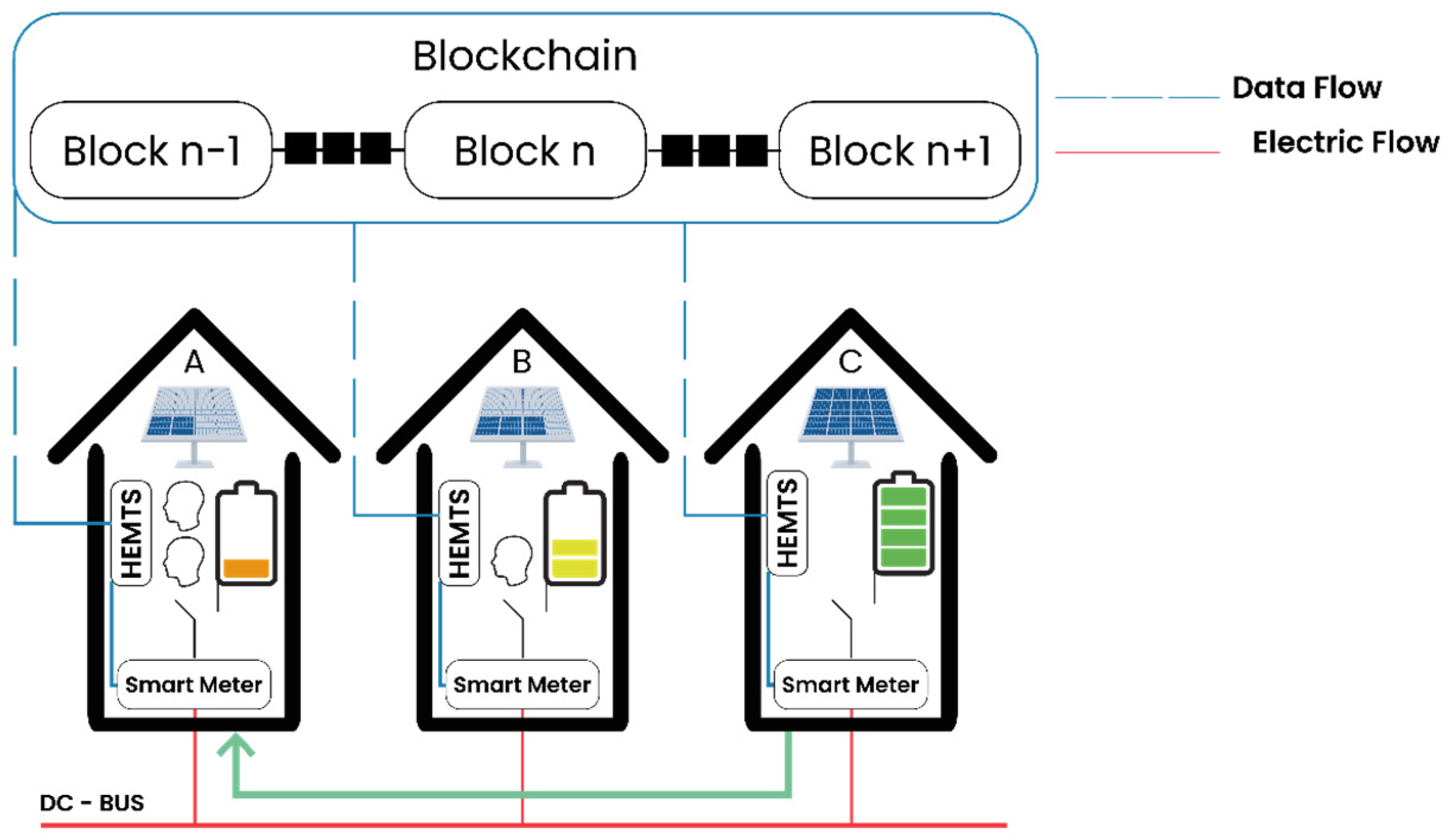
Figure 1. The system components.
Energies 17 03680 g001
Figure 2. The detailed electrical architecture.
Energies 17 03680 g002
Figure 3. The household coupling device.
Energies 17 03680 g003
Figure 4. The switching module (Hx house connection points to the microgrid, SC is the switching module operation control connection).
Energies 17 03680 g004
Figure 5. The microgrid architecture.
Energies 17 03680 g005
Figure 6. The energy exchange process.
Energies 17 03680 g006
Figure 7. HEMTS state diagram.
Energies 17 03680 g007
Figure 8. The Flowchart of the HEMTS. (a) Autonomous mode; (b) prosumer mode; (c) consumer mode.
Energies 17 03680 g008
Figure 9. The household architecture.
Energies 17 03680 g009
Figure 10. The household electrical installation.
Energies 17 03680 g010
Figure 11. The household DC load module.
Energies 17 03680 g011
Figure 12. The proposed controllable PV system. (a) PV panel and projectors; (b) hourly PV production profile; (c) projector power controller.
Energies 17 03680 g012
Figure 13. The Wi-Fi power DC meter.
Energies 17 03680 g013
Figure 14. The microgrid testbed.
Energies 17 03680 g014
Figure 15. Example of household daily demand (sampled at one-minute intervals).
Energies 17 03680 g015
Figure 16. The supplier load: ((a) supplier hourly load profile, (b) scaled supplier load profile.
Energies 17 03680 g016
Figure 17. The requester load profile:.(a) hourly requester load profile, and (b) scaled requester load profile.
Energies 17 03680 g017
Figure 18. The supplier power curves in standalone operation, one-minute sampled.
Energies 17 03680 g018
Figure 19. The requester power curves in standalone operation, one-minute sampled.
Energies 17 03680 g019
Figure 20. The supplier energy curves. (a) supplier in standalone operation, and (b) supplier controlled by HEMTS.
Energies 17 03680 g020
Figure 21. The supplier power curves in exchange mode operation, one-minute sampled.
Energies 17 03680 g021
Figure 22. The requester energy curves. (a) requester in standalone operation, and (b) b-requester controlled by HEMTS.
Energies 17 03680 g022
Figure 23. The requester power curves in exchange mode operation, one-minute sampled.
Energies 17 03680 g023
Figure 24. Community-shared PV and load: (a) Prosumer Community Shared Surplus Production, and (b) Consumer Community-Shared Load.
Energies 17 03680 g024
Table 1. Testbed features.
FeaturesSupplierRequester
PV panel150 Wp80 Wp
Battery12V 40 Ah12 V 40 Ah
Daily total demand290 Wh323 Wh
Table 2. PV households’ energy performance.
Household Energy   Sharing :   E s h p Energy   Request :   E r e q p
Prosumer16%0%
Consumer0%11%
Disclaimer/Publisher’s Note: The statements, opinions and data contained in all publications are solely those of the individual author(s) and contributor(s) and not of MDPI and/or the editor(s). MDPI and/or the editor(s) disclaim responsibility for any injury to people or property resulting from any ideas, methods, instructions or products referred to in the content.