Abstract
With the continuous improvement of wind power penetration in the power system, the volatility and unpredictability of wind power generation have increased the burden of system frequency regulation. With its flexible control mode and fast power adjustment speed, energy storage has obvious advantages in participating in power grid frequency regulation. Therefore, this paper studies the control strategy of wind energy storage combined with primary frequency regulation and proposes a control method of wind energy storage combined with primary frequency regulation based on the operation state of wind turbines. This paper analyzes the reserve power and rotor reserve kinetic energy of wind turbines operating in different wind speed ranges, introduces the fan frequency regulation operation state coefficient to quantify the real-time frequency regulation ability of the unit, regards the fan and energy storage system as independent frequency regulation sources, and designs the control strategy of joint frequency regulation of wind and storage in different wind speed ranges. The energy storage system is employed to participate in frequency control in the low-wind-speed range, thereby addressing the “blind spot” issue of wind turbine unit frequency control alone. In the medium- and high-wind-speed ranges, the real-time complementary output of wind and energy storage power is achieved by assigning weights based on the frequency control operation status coefficient. Finally, the effectiveness of the joint frequency modulation control strategy of wind storage in low-, medium-, and high-wind-speed regions is verified in the simulation model.
1. Introduction
As the world pays more and more attention to renewable energy, wind power generation has become a key area for countries to accelerate sustainable development. However, the wind power output is random, and large-scale access to the power grid will aggravate the power imbalance between the source and the load. Using an additional control strategy to provide a frequency modulation service for wind turbines is an important development direction for wind power grid-connected operation at present [1], and energy storage systems have obvious advantages in participating in power grid frequency modulation by virtue of the flexibility of their control mode and the speed of their power adjustment [2]. Therefore, the wind turbine–storage system combined frequency modulation control strategy is constructed by using an energy storage system to assist wind turbines to participate in frequency modulation in the power system with high wind power permeability, which is an effective method to solve the safe operation problems caused by large-scale wind power access [3,4].
Aiming at the control strategy of energy storage systems participating in primary frequency modulation, scholars at home and abroad have carried out relevant research. Ref. [5] analyzed the changes by state of charge (SOC) for energy storage in the process of frequency modulation and proposed an SOC reconstruction strategy based on virtual droop control to keep the SOC of the energy storage system in the best state possible. In Ref. [6], the frequency modulation dead zone of the energy storage system is set, and the energy storage SOC is used as the reference index. When the frequency deviation of the system exceeds the specified range, the energy storage system provides active support with the rated power and adjusts the energy storage output by using the virtual droop control mode in the frequency recovery stage. In Ref. [7], the energy storage droop control combined with virtual inertia control causes the energy storage system to have a moment of inertia similar to that of the synchronous unit, which effectively reduces the system frequency change rate in the early stage of frequency response. According to the above literature, in the current research on energy storage participation in frequency modulation, the optimization of the SOC of the energy storage system is mostly focused on avoiding the overcharging and discharging of energy storage devices. However, relying solely on energy storage systems to participate in frequency modulation is costly, which reduces the economic performance of frequency modulation.
Therefore, scholars at home and abroad have combined the respective advantages of wind turbines and energy storage systems to conduct a lot of research on the control strategy of the combined wind turbine–storage system to participate in frequency modulation. In Ref. [8], a new model of combined operation of wind and storage was designed considering the influence of energy storage system performance on the frequency modulation process, which reduced the curtailment of wind and increased the total revenue of the combined system. In Ref. [9], energy storage is used to compensate for the inertia loss of wind turbines connected to the grid, the frequency change rate is taken as the input of the control system, and the active power output of energy storage is dynamically adjusted. The frequency modulation effect of traditional units can be achieved by configuring less energy storage [10]. In Ref. [11], a state-of-charge-based feedback droop technique was proposed to coordinate the joint action of wind turbines and fast energy storage systems, and the rapid response of energy storage systems was used to make up for the shortcomings of slow pitch angle adjustment [12,13]. In Ref. [14], a dynamic restoration method of energy storage SOC is proposed, which takes into account both the SOC restoration requirements and the carrying capacity of the power grid. In Ref. [15], a limited torque control link is added to the fan inertia response control, and the energy storage system is used to provide active support after the fan withdraws from frequency modulation, which reduces the secondary frequency drop in the process of rotor speed recovery. In these existing studies, wind turbines and energy storage systems are usually regarded as separate frequency modulation resources that jointly participate in frequency modulation according to their respective frequency modulation coefficients; the operation status of wind turbines in the frequency modulation process and the complementary advantages of their output characteristics are seldom considered.
Accordingly, further in-depth research is needed to realize the coordinated participation of wind storage in frequency modulation under different wind speeds (or fan speeds). On the basis of the above analysis, the wind turbine frequency modulation operation state coefficient is introduced into the wind turbine frequency modulation control method to quantify the real-time frequency modulation capability of the wind turbine. Energy storage systems are used to participate in frequency modulation to make up for the blind area of wind turbines in low wind speeds. At medium-to-high wind speeds, wind turbines provide active support as the main approach, while energy storage systems assist in frequency regulation. The optimized control of wind turbine–storage system combined frequency regulation is achieved under different wind speed conditions, which can effectively solve the safe operation problems caused by large-scale wind power access, enhance the dynamic response characteristics of wind turbine–storage system combined frequency modulation, and improve the frequency stability of the system.
2. Wind Turbine Frequency Modulation Control Strategy
In order to accurately describe the frequency modulation operation state of wind turbines and make the tuning of wind turbine frequency modulation operation state coefficient S more reasonable, the kinetic energy state factor sω and power state factor sp are introduced, respectively.
The current rotor speed of the unit is determined according to the actual wind speed, sω represents the proportion of the actual reserve kinetic energy of the rotor to the maximum reserve kinetic energy of the rotor, and sp characterizes the proportion of the current fan reserve power to the maximum reserve power within its power constraint range, as shown in Equations (1) and (2).
where ΔEk,max and ΔE’k,max represent the maximum reserve kinetic energy of the fan rotor when frequency decreases and rises, respectively, ΔEk represents the actual value of the rotor reserve kinetic energy, ΔPre,max and ΔP’re,max represent the maximum reserve power of the fan when frequency decreases and rises, respectively, and ΔPre,i represents the actual value of the fan reserve power.
Due to the reverse coupling of unit speed and electromagnetic power during frequency modulation, the smaller the median is, the more it can reflect the real frequency modulation ability of the unit, and the operating state coefficient of frequency modulation is temporarily expressed by α, as shown in Equation (3):
When the rotational speed of the unit is low or high, the values of sω and sp are very small, so it is necessary to minimize the participation of the fan in frequency modulation; at medium speed, the values of sω and sp are larger, which requires the rapid improvement of the active power output of the unit and the full utilization of the kinetic energy of the rotor.
The logistic function is selected as the expression of the frequency modulation running state coefficient, as shown in Equation (4), where x represents the independent variable, σ0 represents the initial value, and r represents the change rate of curve. Let the value of K be 1; the maximum value of the function is infinitely close to 1, indicating that the frequency modulation state of the wind turbine is good, the output of the wind turbine can be fully involved in the frequency modulation, and the frequency modulation ability of the unit can be fully utilized. The final optimization function is determined by changing the values of the parameters σ0 and r.
According to Figure 1a, in the case of r determination, σ0 determines the starting position of the curve, and when σ0 is equal to 0.01, the frequency modulation operation state coefficient at the extreme point of the unit speed can be effectively reduced to make it close to 0. In Figure 1b, σ0 is fixed, while the r-value is adjusted. When α > 0.2, the S coefficient increases rapidly, and when a higher value is taken at the α, the S coefficient is maintained at 1, so that the kinetic energy of the rotor is maximized. So, in this work, r is taken as 30. The frequency modulation operation state coefficient of wind turbines is finally expressed as follows:
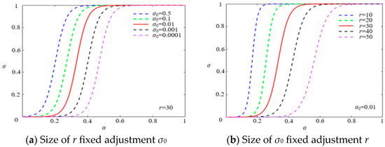
Figure 1.
Logistic curve shape with different values of σ0 and r.
Therefore, with rotor speed ωr as system input, it may be possible to weight the active output of the wind turbine through the S coefficient on the basis of the wind turbine’s participation in the primary frequency modulation control strategy, obtain the actual frequency modulation power PDIFG of the unit, and input it to the rotor side converter control system of the unit to adjust the active output to participate in the frequency modulation. The control block diagram is shown in Figure 2.
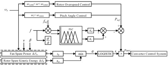
Figure 2.
Block diagram of primary frequency modulation control of fan based on frequency modulation state coefficient.
3. Frequency Modulation Control Strategy of Energy Storage System
3.1. Primary Frequency Modulation Control Strategy Structure of Energy Storage System
In order to realize the independent response of the energy storage system to the frequency disturbance of the power grid, the frequency deviation and frequency change rate of the system are taken as inputs, and the fuzzy algorithm is used to calculate the active output of the frequency modulation, which solves the problem that the frequency modulation characteristics of energy storage are difficult to accurately characterize [16]. In addition, considering the limited capacity of the energy storage system, SOC is also used as the input of the fuzzy controller to avoid overcharging and discharging the energy storage system.
3.2. Design of Fuzzy Controller Considering Energy Storage SOC
To achieve the independent response of energy storage systems to grid frequency disturbances, the paper utilizes system frequency deviation and frequency rate of change as inputs, employing a fuzzy algorithm to calculate its frequency regulation active power output. This approach resolves challenges in accurately characterizing the frequency regulation characteristics of energy storage systems. Additionally, considering the limited capacity of energy storage systems, SOC is used as an input to the fuzzy controller to prevent excessive charging and discharging of the storage system.
Furthermore, weighting is applied to the output of the fuzzy logic controller. On one hand, this facilitates coordination between wind and storage power outputs; on the other hand, it allows a reduction in the frequency and depth of charging and discharging cycles of the energy storage system when wind turbines possess strong frequency regulation capabilities.
3.2.1. Fuzzy
The fuzzy controller adopts a Mamdani-type membership function. Firstly, the quantization factor of the input SOC and the scale factors k1, k2, and k3 of the output PBESS are determined [17].
After the normalization of the quantization factor, the domains of energy storage SOC and PBESS are [0, 1] and [−1, 1], respectively, as shown in Figure 3.

Figure 3.
Domain of SOC and PBESS.
The membership relationship of the input and output variables of the fuzzy logic controller is shown in Figure 4. The basic fuzzy domain of the system frequency deviation Δf is [−0.5, 0.5], and the basic fuzzy domain of the system frequency change rate df/dt is [−0.06]. The basic fuzzy domain of PBESS is [−1, 1], and the fuzzy subset is {negative large (NL), negative small (NS), zero (ZS), positive small (PS), and positive large (PL)}. The basic fuzzy domain of the energy storage system SOC is [0, 1], and its upper and lower limits are set to 0.9 and 0.1, respectively.
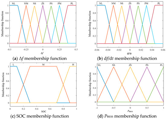
Figure 4.
Membership function of each input and output.
3.2.2. Fuzzy Control Rules
Table 1, Table 2 and Table 3 show the fuzzy logic rules in the case of different energy storage SOC, and the controller evaluates the size of the energy storage SOC in real time to determine the current rules. When the SOC of the energy storage system is low or high, the fuzzy logic rules dictate that the energy storage system can only charge/discharge in one direction, while when the SOC is in the middle level, the fuzzy logic output result is similar to that of the traditional synchronous generator set. The energy storage system has the ability to adjust the active power output in both directions.

Table 1.
SOC = L fuzzy control rules.

Table 2.
SOC = M fuzzy control rules.

Table 3.
SOC = H fuzzy control rules.
3.2.3. Clarity
In the interests of clarity, the area center-of-gravity method is used to obtain the most representative and accurate value of the PBESS fuzzy set. The fuzzy logic inference values of the energy storage power in different SOC cases are shown in Figure 5.
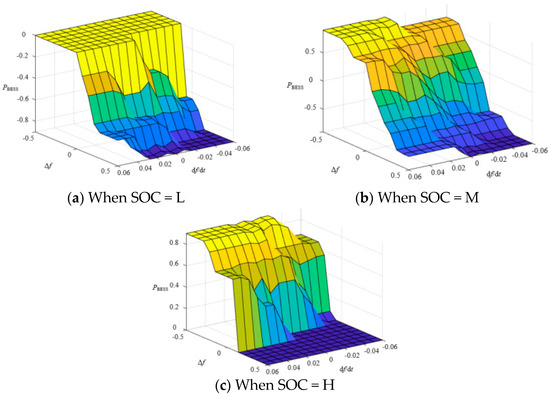
Figure 5.
Fuzzy logic inference values of energy storage power with different SOC values.
According to the fuzzy reasoning results, the energy storage output is negative when the SOC of the energy storage system is low, indicating that the energy storage system can only charge. In contrast, the energy storage output is positive when the SOC of the energy storage system is high, and the energy storage system can only discharge. When the SOC of the energy storage system is in the middle level, the active power output can be adjusted bidirectionally, and the greater the frequency deviation or frequency change rate, the greater the active power output of the energy storage system.
4. Wind Turbine–Storage System Combined Frequency Modulation Control Strategy Considering Different Wind Speeds
When wind turbines participate in primary frequency modulation alone, their ability to support power grid frequency modulation is affected because of the rotor speed, which makes it difficult to provide good support for the frequency stability of the system. This suggests that it is necessary to use wind turbine–storage system combined frequency modulation to improve the frequency stability of the system.
4.1. Wind Turbine–Storage System Combined Frequency Modulation in a Low-Wind-Speed Area
The rotor reserve kinetic energy and reserve power of the fan are small or even zero, so the fuzzy logic controller can only be used to adjust the output of the energy storage system to participate in frequency modulation to provide active power support for the system frequency. The block diagram of wind turbine–storage system combined frequency modulation control in a low-wind-speed area is shown in Figure 6.

Figure 6.
Block diagram of wind turbine–storage system combined frequency modulation control in a low-wind-speed area.
4.2. Wind Turbine–Storage System Combined Frequency Modulation in Medium- and High-Wind-Speed Areas
Considering the primary frequency modulation characteristics of the wind turbine and energy storage system, a wind storage joint primary frequency modulation control strategy model based on wind turbine frequency modulation state coefficient is established, as shown in Figure 7. In this work, [−0.03 Hz] is taken as the primary frequency modulation dead zone, in which the primary frequency modulation is not carried out in order to delay the aging of the equipment and avoid unnecessary frequent charge and discharge.
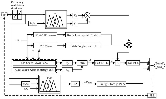
Figure 7.
Block diagram of wind turbine–storage system combined frequency modulation control in medium- and high-wind-speed areas.
When the frequency variation amplitude exceeds the dead zone, the frequency modulation function of each unit of the system starts. In the early stage of frequency response, based on the current wind speed, the frequency modulation capacity of the wind turbine is quantitatively evaluated by using the S coefficient, and the frequency modulation output of the wind turbine is determined; the energy storage system participates in frequency modulation through a fuzzy logic controller and the 1−S coefficient. With the advance of the frequency modulation process, due to the continuous change of wind turbine speed and active power output, the S coefficient is adjusted dynamically on the premise of ensuring the safety of wind speed and power, so that the wind and storage capacities are coordinated and complementary. When the wind turbine withdraws from the frequency modulation due to the lack of frequency modulation capacity, the energy storage system can still provide continuous active power support for the system according to the 1−S coefficient, assist the wind turbine speed recovery, restrain the secondary frequency drop, and improve the dynamic performance of the system frequency response.
5. Simulation Verification
The energy storage system is connected to the No. 3 bus of the wind turbine simulation model in Figure 8, and the control models of wind turbine–storage system combined frequency modulation in low, medium, and high wind speed areas are built, respectively. The rated capacity of the two synchronous generator units is 50 MW each, while the rated capacity of the equivalent wind turbine unit is 36 MW. The fixed active power load is set at 60 MW. The energy storage capacity is configured as 2 MW/1 MWh, and the initial SOC is 35%.
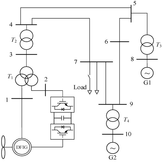
Figure 8.
Grid-connected simulation model of wind turbine.
5.1. Wind Turbine–Storage System Combined Frequency Modulation in a Low-Wind-Speed Area
In the simulation model, the wind speed is set to 6 m/s, the wind turbine is limited by the rotor speed and cannot participate in system frequency modulation, and the energy storage system alone provides active power support and undertakes the frequency modulation task of the system. The simulation results are shown in Figure 9.
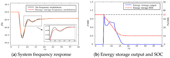
Figure 9.
Simulation results of wind turbine–storage system combined frequency modulation in a low-wind-speed area.
When the load increases suddenly, the fuzzy logic controller determines the active power output of the energy storage system according to the system frequency deviation, frequency change rate, and SOC, and supports the frequency response of the energy storage system. When there is no energy storage system participation in the frequency modulation, the lowest frequency of the system is 49.66 Hz, and it is raised to 49.68 Hz after adding the energy storage system. With the deepening of the frequency modulation process, the energy storage SOC decreases, and the output of the energy storage system decreases accordingly. When the SOC is reduced to 10% of the lower limit, the energy storage system withdraws from frequency modulation to prevent excessive discharge from shortening the life of the energy storage device.
This suggests that the participation of the energy storage unit in frequency modulation in the low-wind-speed area makes up for the “blind area” in which the wind turbine has no frequency modulation ability, and the frequency response characteristic of the system is improved.
5.2. Wind Turbine–Storage System Combined Frequency Modulation in a Medium-Wind-Speed Area
In the simulation model, the wind speed is set to 8 m/s, and the wind turbine participates in the comparative analysis of frequency modulation and the wind turbine–storage system combined primary frequency modulation control strategy through rotor overspeed control, as shown in Figure 10.
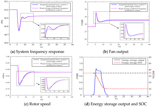
Figure 10.
Simulation results of wind turbine–storage system combined frequency modulation in a medium-wind-speed area.
In the case of wind speed of 8 m/s, the wind turbine is mainly involved in frequency modulation at 5~6.5 s when the load is bursting. With the progress of frequency modulation, the frequency deviation of the system is the largest at about 6.5 s, the speed of the fan drops to the lowest point, and the frequency modulation ability weakens. At this time, the fuzzy controller is used to weigh the quantitative reasoning results of Δf, df/dt, and the 1 m S coefficient, and the energy storage system rapidly increases the active power output to provide active power support for the system. With the frequency change rate close to zero, the active power output of the energy storage system gradually decreases, but in order to make up for the decrease in fan output caused by the decrease of the S coefficient, the active power output is still maintained at a certain level. At about 11 s, the S coefficient of the active power output of the energy storage system continues to decrease and rise again to compensate for the lack of active power caused by the weakening of the wind turbine’s frequency modulation capacity and speed recovery. In contrast, the secondary frequency drop under the wind turbine–storage system combined frequency modulation is reduced, and the speed recovery process is relatively smooth. When the SOC is reduced to 10%, the energy storage system withdraws from frequency modulation, and the steady-state error is finally consistent with the rotor overspeed control participating in frequency modulation, indicating that the fuzzy controller can avoid excessive charging and discharge in the case of the insufficient frequency modulation capacity of the energy storage system.
In the two frequency modulation strategies, the lowest value of the system frequency, the relative degree of the secondary frequency drop, and the steady-state frequency are compared in Table 4. Obviously, the wind turbine–storage system combined frequency modulation can prevent the wind turbine from participating in frequency modulation excessively, use the energy storage system to provide active power support, assist the recovery of the rotor speed of the fan, restrain the secondary drop of the frequency, and enhance the stability of the frequency of the system.

Table 4.
Comparison of simulation results of medium wind speed.
5.3. Wind Turbine–Storage System Combined Frequency Modulation in a High-Wind-Speed Area
In the simulation model, the wind speed is set to 12 m/s, and the wind turbine participates in the primary frequency modulation alone. The wind turbine–storage system primary frequency modulation of wind and storage, considering the running state of the frequency modulation of the fan, is compared and analyzed as shown in Figure 11.
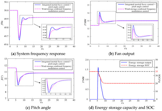
Figure 11.
Simulation results of wind turbine–storage system combined frequency modulation in high-wind-speed area.
In the high-wind-speed area, the fan frequency modulation state coefficient S is small, and the response speed of the pitch angle control participating in the frequency modulation is slow, while the energy storage system has a faster response speed when participating in frequency modulation. When the load increases suddenly, the energy storage system rapidly increases its active power output and supports the frequency response of the system. At the same time, wind turbines increase their active power output by reducing the pitch angle. With the progress of frequency modulation, the frequency of the system tends to gradually become stable, and the energy storage system withdraws from frequency modulation. The wind turbine maintains the stability of the system frequency separately through integrated inertia fuzzy control and pitch angle control.
In the two frequency modulation strategies, the lowest value of the system frequency, the relative degree of the secondary frequency drop, and the steady-state frequency are compared in Table 5. According to the comparison, the combination of wind and storage participates in frequency modulation so that the lowest frequency of the system is increased from 49.66 Hz to 49.68 Hz when the fan is modulated separately, and the secondary frequency drop is basically eliminated.

Table 5.
Comparison of high-wind-speed simulation results.
According to the above analysis, the wind–storage joint participation in frequency modulation not only has the stable reserve capacity of pitch angle control in the high-wind-speed area but also gives full play to the advantages of the fast response speed of the energy storage system, which improves the regulation effect of wind turbines participating in frequency modulation alone and enhances the frequency stability of the system.
6. Conclusions
This paper analyzes the reserve power and rotor kinetic energy of wind turbines operating in different wind speed ranges, introducing the real-time frequency regulation capability of wind turbines under frequency modulation operation. Wind turbines and energy storage systems are treated as independent frequency regulation sources, proposing a method for the coordinated primary frequency control of the wind turbine and storage system. Simulation results demonstrate that in low-wind-speed conditions, integrating energy storage systems into frequency regulation raises the system’s minimum frequency from 49.66 Hz to 49.68 Hz, compensating for the inadequacy of wind turbines operating alone without frequency regulation capability. In moderate wind speeds, the energy storage system provides active power support to assist wind turbines in restoring rotor speed, resulting in a 0.02 Hz increase in the system’s minimum frequency and a 0.01 Hz reduction in relative frequency secondary drops compared to wind turbines operating alone. In high-wind-speed conditions, coordinated frequency regulation by the wind turbine and storage system raises the system’s minimum frequency from 49.66 Hz to 49.68 Hz and substantially mitigates secondary frequency drops.
Author Contributions
Conceptualization, L.Y. and G.M.; methodology, J.W. and Y.L.; software, Y.L.; validation, L.Y. and Y.C.; formal analysis, S.C.; investigation, Y.L and Y.C.; resources, K.X.; data curation, L.Y.; writing—original draft preparation, Y.L. and J.W.; writing—review and editing, J.W. and G.M.; visualization, Y.C.; supervision, L.Y. and S.C.; project administration, G.M.; funding acquisition, L.Y. All authors have read and agreed to the published version of the manuscript.
Funding
This research was funded by The State Grid Henan Electric Power Company Technology Project, grant number 5217L0230007.
Data Availability Statement
The original contributions presented in the study are included in the article, further inquiries can be directed to the corresponding author.
Conflicts of Interest
Authors Linlin Yu, Yuming Cheng and Shuyu Chen were employed by the Economic Research Institute of State Grid Henan Electric Power Company. The remaining authors declare that the research was conducted in the absence of any commercial or financial relationships that could be construed as a potential conflict of interest.
References
- Wang, H.M. Research on Security Assessment and Control Strategy of Wind Power Interconnected Power System. Ph.D. Thesis, University of Electronic Science and Technology, Chengdu, China, 2022. [Google Scholar]
- Wang, Y.; Zou, R.; Liu, F.; Zhang, L.; Liu, Q. A review of wind speed and wind power forecasting with deep neural networks. Appl. Energy 2021, 304, 117766. [Google Scholar] [CrossRef]
- Xu, Y.C.; Jiang, W.J.; Sun, S.H.; Lu, M. Quantitative Assessment Method for Transient Voltage of Distribution Network with High-Penetration Wind Power. Electr. Power 2022, 55, 152–162. [Google Scholar]
- Gong, H.Y.; Zhou, Q.; Guo, Q.; Qin, X.H.; Zhao, S.S.; Su, L.N. Improvement and Application of Frequency Analysis Modules for Power System in High Proportion of Renewable Energy Situation. Power Syst. Technol. 2021, 45, 4603–4612. [Google Scholar] [CrossRef]
- Zhao, X.L.; Gui, Y.; Fu, B.; Zhang, D.H.; Li, P. Adaptive Grouping Strategy of the Battery Energy Storage System Participating. Power Syst. Clean Energy 2022, 38, 116–125. [Google Scholar]
- Fang, H.Y.; Ma, P. Adaptive Droop Control Strategy Considering Frequency Modulation Dead Band of Hybrid Energy Storage. Electr. Manuf. 2021, 16, 213–222. [Google Scholar]
- Li, J.H.; Hou, T.; Mu, G.; Yan, G. Primary Frequency Regulation Strategy with Energy Storage System Based on Weight Factors and State of Charge Recovery. Autom. Electr. Power Syst. 2020, 44, 63–72. [Google Scholar]
- Zhu, Y.; Qin, L.; Yan, Q.; Wei, Z. Wind-storage combined frequency regulation strategy and optimal configuration method of energy storage system considering process of frequency response. Electr. Power Autom. Equip. 2021, 41, 28–35. [Google Scholar]
- Liang, K.; Peng, X.T.; Qin, S.; Wang, J.R.; Zhang, Z.; Chen, R.J. Study on Synergetic Control Strategy for Optimizing Frequency Response of Wind Farm Augmented With Energy Storage System. Proc. CSEE 2021, 41, 2628–2641. [Google Scholar]
- Li, J.H.; Song, C.X.; Lan, F. Optimal control strategy for frequency response of isolated power system based on synergetic control. Electr. Autom. 2023, 43, 133–140. [Google Scholar] [CrossRef]
- Dong, T.; Zhai, B.; Li, X. Optimal Control Strategy for Combined Wind-storage System to Participate in Frequency Response. Power Syst. Technol. 2022, 46, 3980–3989. [Google Scholar]
- Jiang, H.; Cai, J.; Xiao, R.; Wang, S.; Xie, Y.; Tang, X. A wind-storage coordinated control strategy for improving system frequency response characteristics. Electr. Power Autom. Equip. 2021, 41, 44–51. [Google Scholar] [CrossRef]
- Liu, Q.X.; He, S.Z.; Lu, W.H.; Wang, H.H. Model predictive control method for battery energy storage assisting secondary frequency modulation. Electr. Meas. Instrum. 2020, 57, 119–125. [Google Scholar] [CrossRef]
- Chen, C.; Wang, Y.; Zhou, K.; Huang, Z. Frequency regulation optimization for wind storage based on frequency regulation reliability and state of charge in isolated island off-grid. Energy Sci. Eng. 2022, 11, 192–205. [Google Scholar] [CrossRef]
- Yan, Q.C.; Gu, W.; Fan, L.X.; Tang, Y.; Liu, Y. Energy Storage Assists Wind Turbines to Participate in Grid Frequency Regulation Control Strategy Research. Mod. Electr. Power 2022, 39, 537–546. [Google Scholar]
- Ma, Y.B. Optimal Control Strategy of Wind and Energy Combined System Participating in Primary Frequency Regulation of Power System. Master’s Thesis, Northeast Electric Power University, Jilin, China, 2019. [Google Scholar]
- Shang, Q.Y.; Li, F.T.; Wang, S.; Li, Y.; Yin, C. Primary Frequency Modulation Strategy for Wind-storage Combined System Based on Multivariable Fuzzy Logic Control. Power Syst. Technol. 2023, 47, 2344–2360. [Google Scholar] [CrossRef]
Disclaimer/Publisher’s Note: The statements, opinions and data contained in all publications are solely those of the individual author(s) and contributor(s) and not of MDPI and/or the editor(s). MDPI and/or the editor(s) disclaim responsibility for any injury to people or property resulting from any ideas, methods, instructions or products referred to in the content. |
© 2024 by the authors. Licensee MDPI, Basel, Switzerland. This article is an open access article distributed under the terms and conditions of the Creative Commons Attribution (CC BY) license (https://creativecommons.org/licenses/by/4.0/).