1. Introduction
With the growth in the global scale of renewable energy utilization, photovoltaic (PV) power generation has received extensive attention from various countries due to its advantages of being easily accessible, clean, and renewable [
1]. However, the intermittent and stochastic characteristics of PV power generation can lead to large fluctuations in PV power, affecting the reliability of grid power supply, operational stability, and power quality [
2]. As the PV penetration rate and installed capacity continue to increase, the negative impact of its volatility has become more prominent. It is now urgently necessary to find a solution for how to more efficiently smooth fluctuations in PV power and lessen their influence on the power system.
The configuration of an ESS in a photovoltaic power station can smooth the fluctuation of photovoltaic power, which supports the safe and stable operation of the electrical grid. Because the power-type ESS components and energy-type ESS components can complement each other in their use characteristics, the method of using a hybrid energy storage system (HESS) to cooperate with each other can make up for the shortcomings of a single ESS technology, thereby extending the life of ESS components and improving the economy of power system operation [
3]. Lithium batteries can be used as a typical energy-type ESS due to their high energy density, high safety, and long charging and discharging duration. Supercapacitors offer high power density, long service life, and fast response speed, which can be used as a typical power-type ESS [
4]. Therefore, lithium batteries and supercapacitors are selected to form an HESS in this paper.
Studies have shown that the configuration of an HESS consisting of energy-type ESS and power-type ESS can effectively smooth PV power fluctuations, reduce the effect on the power grid, and improve the friendliness of PV grid connection [
5,
6,
7]. Scholars have currently conducted pertinent research on this. The literature [
8] decomposes PV power using the wavelet packet algorithm, but there is the problem that the wavelet base and the number of decomposition layers are difficult to determine. If the fluctuations are smoothed using the first-order or second-order filtering approach, there are usually problems such as difficulty in selecting the time constant and time delay [
9,
10]. The literature [
11,
12] uses EMD and CEEMD to decompose the total power, respectively, but these methods cannot solve the more serious modal aliasing problem. Variational modal decomposition (VMD) is a fully non-recursive and adaptive signal processing technique; it can resolve the modal aliasing issue of EMD, CEEMD, and other algorithms [
13]. However, if the number of penalty factor
and modes
of the VMD algorithm are not set correctly, there is a risk of either over- or under-decomposition [
14]. The literature [
15] utilizes dung beetle optimizer (DBO) algorithm to optimize parameters
and
, but suffers from problems such as slow convergence and falling into local optimality.
Model predictive control (MPC) can be used as an effective method for smoothing renewable energy power fluctuations with good performance and high reliability [
16]. The literature [
17] smoothed wind power fluctuations in real time using an MPC algorithm, but only with the goal of reducing the ESS output. Current MPC algorithms mostly set the weights of the objective function to a fixed value [
18,
19] and cannot adaptively change the weights of each part based on how the ESS is working in real time, which imposes limitations on their performance.
The service life of the HESS mainly depends on the lithium battery. Frequent power fluctuations and switching of charge and discharge states will damage the life of lithium batteries, while frequent charging and discharging of supercapacitors will not significantly damage their performance. Fuzzy logic control uses linguistic variables and performs fuzzy inference operations after fuzzification of inputs and outputs and finally defuzzification, which can be applied to complex systems with high uncertainty. For the problem of the SOC of ESS overrun, it is common to apply fuzzy control to two different types of energy storage concurrently, but due to the simultaneous reduction of the power of both, it may lead to the grid-connected fluctuation rate not being satisfiable, and it will lead to the introduction of high-frequency components to the battery’s power, which will cause it to be charged and discharged frequently, damaging its life. Furthermore, due to the small capacity of the supercapacitor, the fuzzy control effect is sometimes unsatisfactory [
20,
21]. Little research attention has been paid to the problem of unsatisfactory grid-connected volatility that may result from power curtailment after the use of fuzzy control.
This paper proposes an HESS power adaptive optimization strategy based on improved model predictive control and improved DBO-VMD. The main contributions and innovations of this work are as follows:
- (1)
A new adaptive model predictive control for smoothing PV power fluctuations is used. Compared to traditional single-objective MPC and traditional fixed-weight two-objective MPC, the proposed method is implemented by introducing an adaptive weight coefficient related to the SOC of the ESS, with the objective function of the MPC adjusted in real time to realize the adaptive operation of the ESS. It is able to take into consideration the ESS’s charging and discharging performance as well as storage protection, using the adaptive MPC to obtain the overall ESS power as well as the PV grid-connected power to meet the requirements;
- (2)
A VMD algorithm optimized by the MSADBO algorithm is proposed to decompose the total HESS power, which improves the performance of the VMD algorithm and is faster and easier to jump out of the local optimal solution than the original DBO algorithm, and avoids the serious mode-mixing problem caused by traditional algorithms such as EMD and CEEMD. The initial allocation of power is performed according to the storage characteristics;
- (3)
A new ESS power optimization strategy is proposed, which is able to significantly reduce the number of lithium battery charging and discharging conversions and ensure that the supercapacitor and lithium battery SOC do not exceed the limit, and the over-limit of grid-connected volatility after optimization is avoided, and it overcomes the problems caused by the traditional power allocation and optimization method.
This paper is organized as follows:
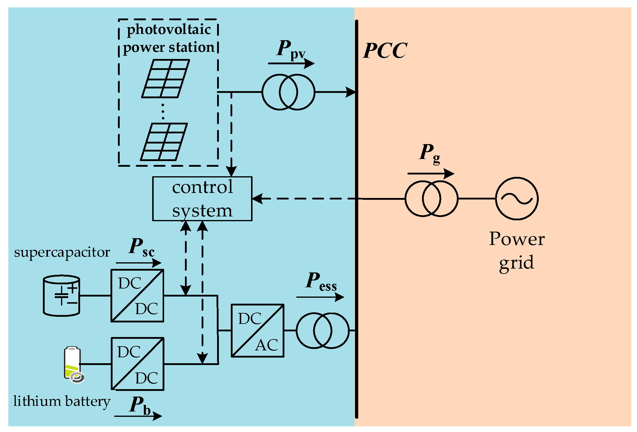
Section 2 introduces the PV-HESS structure and the principle of the proposed adaptive model predictive control to smooth power fluctuations.
Section 3 proposes the MSADBO-VMD decomposition of the total power of the HESS and initial power allocation method.
Section 4 proposes a new ESS power optimization strategy.
Section 5 gives the example simulation and comparison verification results. Finally,
Section 6 summarizes the conclusions obtained.
3. MSADBO-VMD Decomposition
After obtaining the total power of the HESS, it needs to be decomposed into high-frequency components and low-frequency components, and then assigned to the supercapacitor and the lithium battery to adapt to the different operating characteristics of the two. Based on the shortcomings of EMD, CEEMD, and the original VMD algorithm analyzed in the introduction, and the shortcomings of the original DBO algorithm for optimization, the proposed MSADBO-VMD algorithm is used in this section to complete the decomposition of the total power of the HESS and the initial allocation of the power.
3.1. DBO Algorithm
Inspired by the behaviors of the dung beetle (DB), which include ball rolling, dancing, foraging, breeding, and stealing, Xue J et al. [
24] presented the DBO algorithm in 2023. A colony of DBs is made up of rolling DBs, breeding DBs, stealing DBs and small DBs. The position of the rolling DB is updated throughout rolling. The rolling mathematical model can be represented as:
Here, , denotes the quantity of iterations and denotes the location of the th DB at iterations, is the deflection coefficient, is a constant of , is taken to be −1 or 1, simulates the variation in light intensity, and is the global worst location.
The method for choosing boundaries for simulating the area where female breeding DB spawn is:
Here, is the current locally optimal location, and represent the upper and lower bounds of the spawning area, while and represent the upper and lower bounds of the optimization process, and the maximum number of iterations is , .
The location of the breeding DB in the iterative process is:
Here, is the location of the breeding DB in the iteration, and are mutually independent random vectors.
The following defines the boundary of the ideal feeding region for small DBs:
Here,
is the global best location,
and
are the higher and lower bounds of the best foraging area, respectively. The locations of the small DBs are as follows:
Here, is the location of the th small DB in the th iteration, is a normally distributed random number, is a random vector, .
During the iteration, the stealing DB is located at the following location:
Here, is the location of the th thieving DB in the th iteration, is a normally distributed random vector, and is a constant.
3.2. MSADBO Algorithm
The DBO algorithm has certain advantages, but it also has disadvantages, for example, being susceptible to falling into local optima. In the same year, Jincheng Pan et al. [
25] proposed the MSADBO algorithm, which improves the performance of the algorithm by using a Bernoulli mapping strategy, incorporating adaptive Gaussian-Cauchy variational perturbation, and employing the improved sinusoidal algorithm approach.
The location of the DB individual is initialized through Bernoulli mapping. The resulting values are first projected, employing the Bernoulli mapping relation, into the area of chaotic variables, and then the resulting chaotic values are mapped into the algorithm’s starting space via a linear transformation,
. The Bernoulli mapping expression is as follows:
Optimization using the MSA algorithm: The Modified Sine Algorithm (MSA) utilizes the sinusoidal function in mathematics for iterative optimization search with strong global exploration [
26]. The position update formula for the modified sine algorithm is as follows:
where
is the inertia weight coefficient, for the
th iteration,
is the
th component of the optimal individual position variable, and
,
. The expression of
is:
where the minimum and maximum values are
and
, respectively, of
. The expression for
is:
Applying MSA to the DBO algorithm, the improved location update expression is:
Here, , .
- 3
Adaptive Gauss-Kersey mixed-variance perturbations:
The literature [
25] proposes an adaptive hybrid perturbation approach based on Gaussian-Corsey perturbation that combines the respective advantages of the Cauchy and Gaussian variants. The better position is chosen to proceed to the next iteration in order to broaden the scope of the population search by comparing its location prior to and following the mutation. The following is the concrete formula for this process:
Here, is ’s location following a Gaussian-Corsey perturbation, and is individual ’s ideal position at the th iteration, and denote the Gaussian and Corsey variational operators, respectively. , .
The greedy rule is introduced as in Equation (28) to guarantee that the fitness value of the new location obtained following the mutation perturbation is better than the fitness value of the original position and
is the adaptation function.
3.3. VMD Algorithm
The VMD algorithm effectively reduces the phenomenon of modal aliasing after decomposition compared to algorithms such as EMD and CEEMD. The IMF obtained by decomposition is as follows:
Here, is the th modal component obtained from the decomposition; is the time; is the amplitude of ; is the phase of ; and is the frequency of . The steps are as follows:
The VMD variational model is first built with the constraints set to
. The model is as follows:
where
is the full modal component;
is the center frequency. and
is the function of the unit impulse. The constructed VMD variational model is then solved. The Lagrange function is constructed as follows:
where,
is the Lagrange operator and
is the penalty factor. After that, the alternating direction multiplier method is applied for iterative calculations and Parseval/Plancherel transformations are performed, and the final expressions for each IMF and center frequency are obtained as follows:
The Fourier inverse transform of yields the real part which is the corresponding time domain component.
3.4. MSADBO-VMD
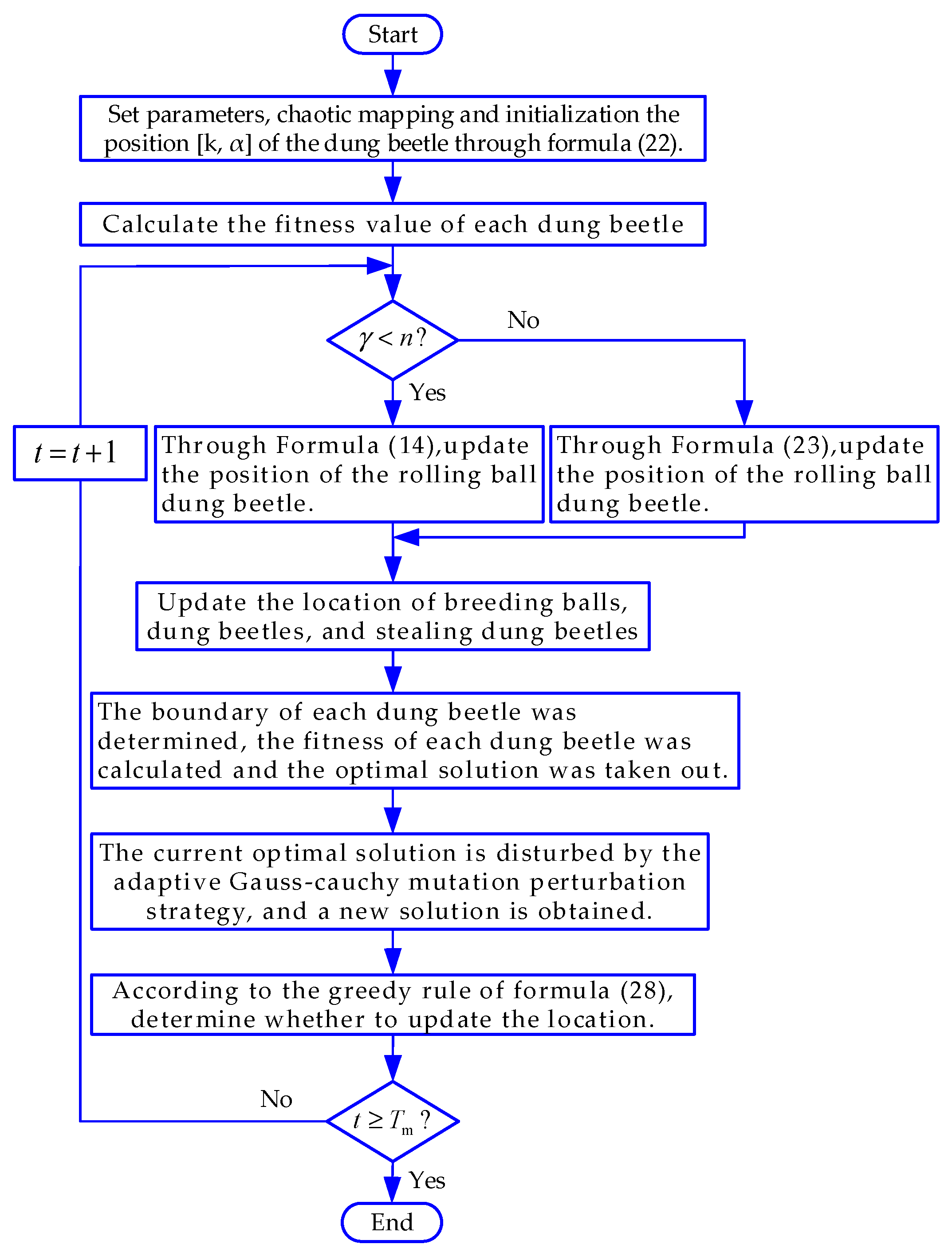
If parameters
and
of the VMD method are not chosen appropriately, they may cause over- or under-decomposition. In this paper, VMD is optimized by the MSADBO algorithm, and the fitness function is envelope entropy. Through iterative updating, constantly searching for the minimal value of the fitness function until the criteria for termination are met, the optimized values of
and
are obtained. The flow chart for optimization is shown in
Figure 2.
After the HESS’s overall power is decomposed by MSADBO-VMD, according to the respective characteristics of the lithium battery and supercapacitor, the lithium battery bears one of the low-frequency components and the supercapacitor bears one of the high-frequency components. The initial distribution expression is as follows:
where
is the cutoff point of the high-low frequency components,
and
are the supercapacitor’s and lithium battery’s initially allocated power, respectively.
4. Energy Storage Power Optimization Strategies
When the energy storage operates in the overcharge/discharge region, it not only lacks charge/discharge margins, but working in this region will also seriously deplete its lifetime [
20]. The number of transitions from charge to discharge significantly affects the lifetime of lithium batteries, while the lifetime of supercapacitors is mainly affected by the number of overcharge/discharge transitions. In order to prevent the SOC of both of them from exceeding the limit, the traditional method is to apply fuzzy control to both of them at the same time [
27].
However, although fuzzy control can prevent the two SOCs from exceeding the limit to a certain extent, the simultaneous reduction of the power of the two may lead to the grid-connected fluctuation rate not meeting the requirements; and the reduction of the supercapacitor power will lead to the lithium battery’s power being augmented with high-frequency components, resulting in frequent charging and discharging, and impairing its lifespan [
20,
21]. For this reason, this research proposes the following energy storage power optimization strategy:
4.1. Strategies for Cutting Down on Charge/Discharge Numbers Conversions of Lithium Batteries
Lithium batteries are suitable for bearing the power of low-frequency, large-scale, fluctuations, while supercapacitors are suitable for bearing high-frequency power [
28]. After the initial allocation of the lithium battery power command, there are some low-amplitude components, which will result in the lithium battery needing to be charged and discharged more frequently and shorten its lifespan. The supercapacitor allows a great number of charge/discharge cycles, so this part of the low-amplitude component can be assigned to the supercapacitor.
where
and
are the power commands of the two after adjustment, and
is the set threshold, which can be selected according to the actual situation. In this paper, we take
MW.
4.2. SuperCapacitor Self-Recovery and Anti-Overrun Strategy
The small capacity of the supercapacitor makes it easy for the SOC to exceed the limit during operation. In view of the above shortcomings of fuzzy control of the supercapacitor, this paper proposes a strategy to prevent overrunning. When judging that will exceed the limit, according to the state of charge/discharge and the original power command, an immediate adjustment is made to realize self-recovery and ensure that will not exceed the limit. Taking into account that the cost of supercapacitor capacity per unit capacity is relatively high, the use of this strategy can appropriately reduce the capacity of the supercapacitor configuration to improve the economy. At the same time, due to the sum of the power of the supercapacitor and lithium battery always being equal to the total power required for hybrid energy storage, it prevents the effects on PV grid-connected volatility and power grid due to supercapacitor adjustment. Define the coefficient to describe the state of charge/discharge of the lithium battery and supercapacitor.
- (a)
When , the Supercapacitor Charging Margin Is Insufficient:
When
, the supercapacitor and lithium battery are in the same charging or discharging state. If the supercapacitor assigned power is discharging, the total HESS output is discharging, and the absolute value is greater than the supercapacitor. Currently, the entire output of the HESS is assigned to the supercapacitor, not only to accelerate the
self-recovery, but also to reduce the number of times that the lithium battery is charged and discharged. If the supercapacitor assigned power is charging, the total hybrid energy storage output is charging. At the moment, the total HESS output is assigned to the lithium battery, to prevent the
from exceeding the limit.
When
, the two charge and discharge states are opposite, and the absolute value of the supercapacitor power is less than the absolute value of the lithium battery power. Currently, the total HESS output charge and discharge state is opposite to the supercapacitor. If the allocated power is discharged, it does not change, and
self-recovers. If the allocated power continues charging, it will lead to
overrunning. At this time, the proposed approach fully utilizes the fact that the total output is discharged, and the total output is allocated to the supercapacitor, which not only realizes the self-recovery of
, but may also reduce the number of times the lithium battery is charged and discharged.
When
, the two charge and discharge states are opposite, and the absolute value of the supercapacitor power is higher than the power of the lithium battery. At this moment, the total output of HESS charge/discharge state is the same as that of the supercapacitor. If the assigned power is discharged, it does not change and
self-recovers. If the assigned power continues charging, there will be
overrunning. At this time, the total output of HESS is charging, and the total output of HESS is assigned to the lithium battery to prevent
overrunning.
- (b)
When , the supercapacitor discharge margin is insufficient, for the same reason:
- (c)
When , the supercapacitor charge and discharge margin is adequate, .
4.3. Strategies to Prevent Lithium Battery SOC Overruns
After being processed by the strategy in the previous section, the supercapacitor overrun situation is avoided, but the lithium battery may still overrun during operation. For this reason, this section uses fuzzy control to optimize the lithium battery to prevent from exceeding the limit and protect the lithium battery.
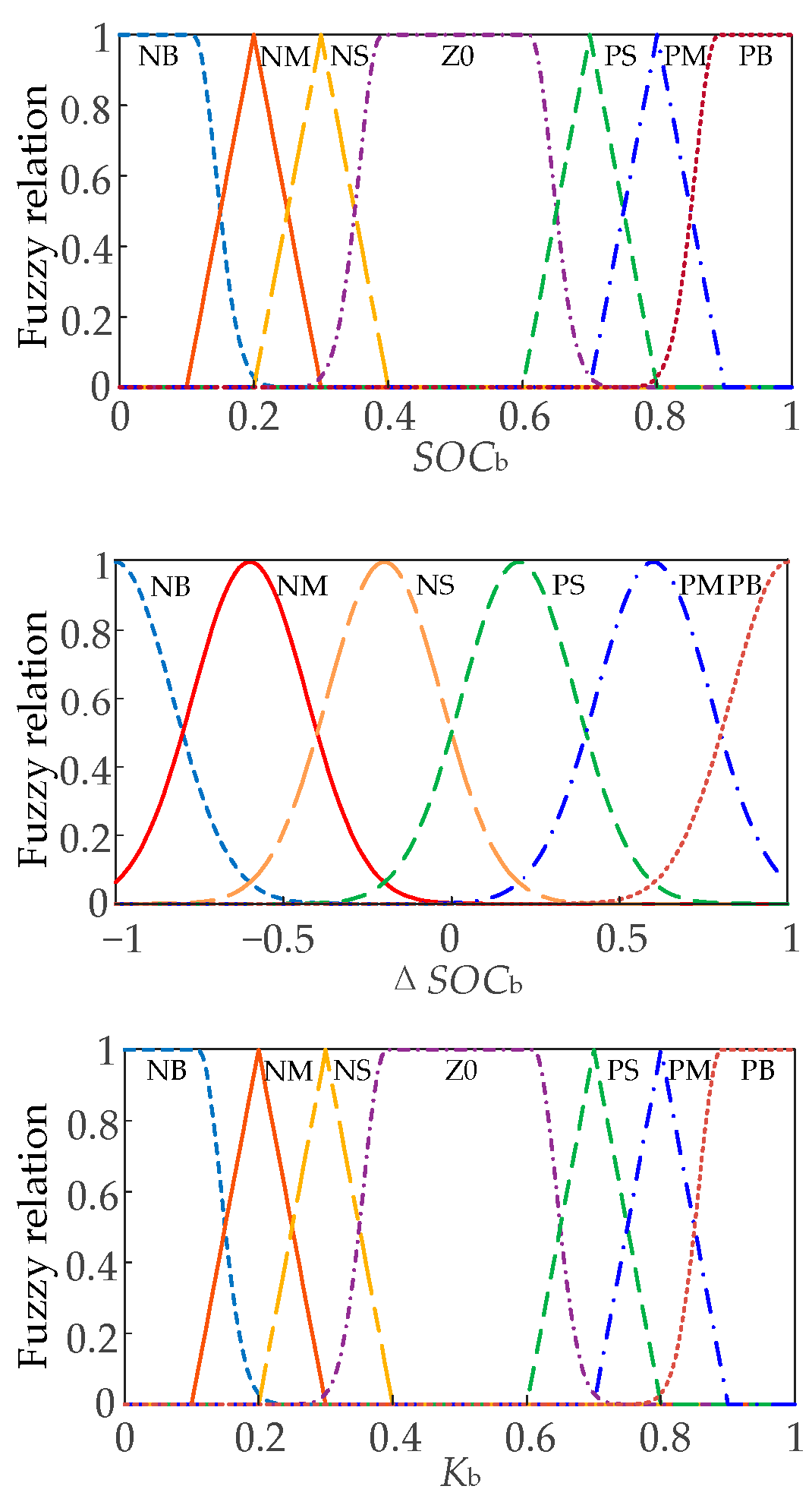
The fuzzy controller has two input variables
and
, and the output variable is
. Combining expert experience to formulate fuzzy logic rules, when
, the larger
is, the smaller the output variable
should be; when
, the smaller
is, the smaller the output variable
should also be. For
, {NB, NM, NS, ZO, PS, PM, PB} denote {very small, small, smaller, medium, large, big, very big}; for
, {NB, NM, NS, PS, PM, PB} denote {negative-high, negative-medium, negative-low, positive-low, positive-medium, positive-high}; and for
, {NB, NM, NS, ZO, PS, PM, PB} denote {very small, small, small, medium, large, big, very big}. After the fuzzy control optimization, the lithium battery receives a power command of
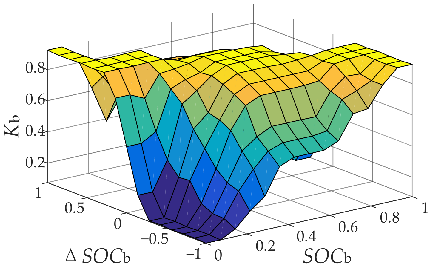
. The fuzzy controller’s membership functions, the fuzzy control rule, and the fuzzy control surface diagram are as
Figure 3,
Table 1 and
Figure 4.
4.4. Preventing the Volatility of Optimized Grid-Connected Power from Crossing the Limit
The lithium battery power after fuzzy control optimization avoids
exceeding the limit, but due to a certain degree of attenuation of the energy storage power, it may lead to the PV grid-connected fluctuation rate not meeting the requirements, which adversely affects grid operation. In order to prevent the fuzzy control from excessively reducing the power of the lithium battery, which leads to exceeding the limit of grid-connected fluctuation rate, this section corrects the power of the lithium battery after fuzzy control optimization to prevent the fluctuation rate of grid-connected power from exceeding the limit.
where
,
is the grid-connected volatility within 1 min after optimization by
Section 4.1,
Section 4.2 and
Section 4.3,
is the upper limit of the grid-connected volatility allowed within 1 min, and in this paper, we take
, and
is the margin set to prevent the volatility from exceeding the limit, which can be set according to the actual requirements.
5. Case Study
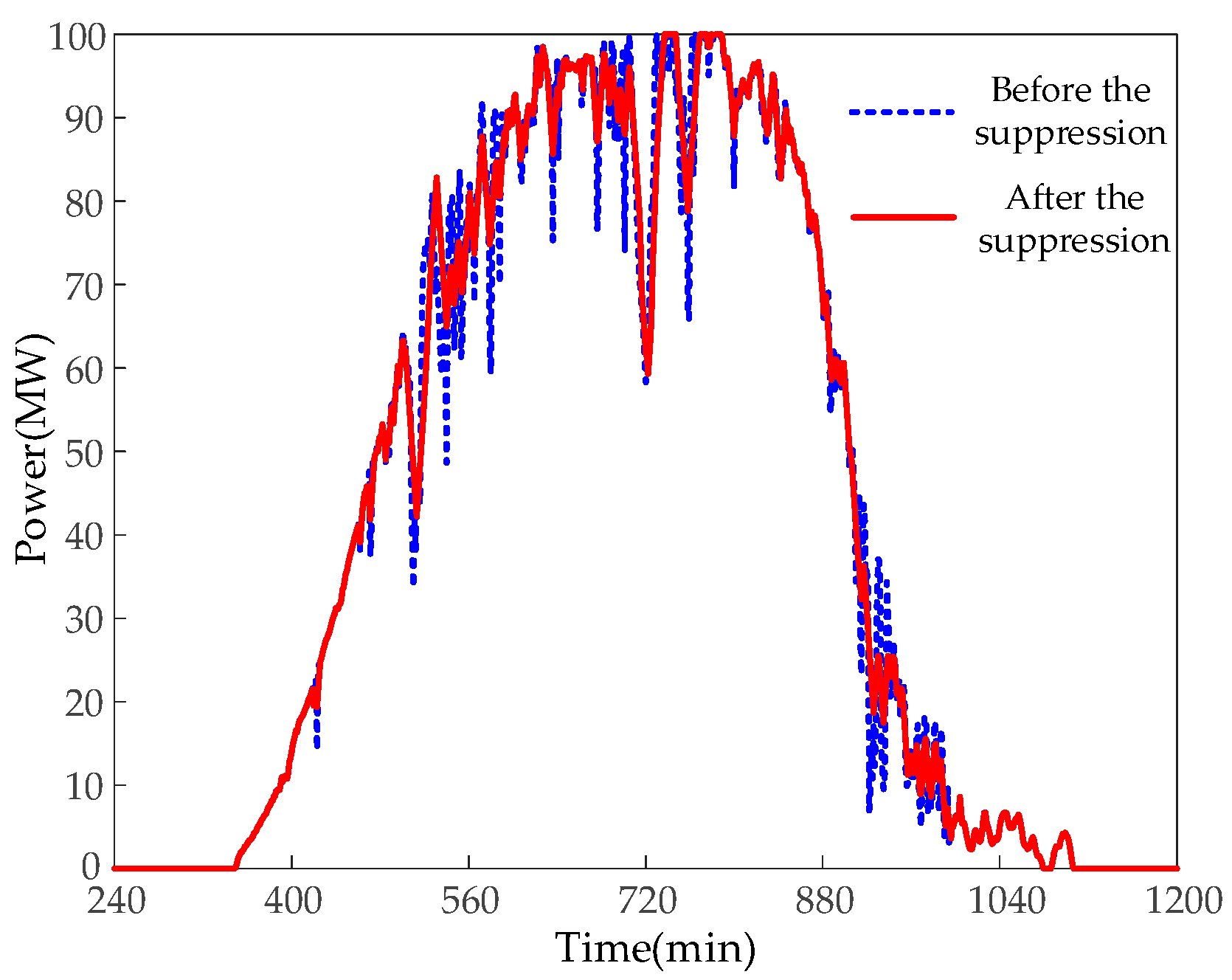
To confirm the efficacy of the proposed strategy, this paper uses the measured PV power data of a typical day of a 100 MW PV power plant in a certain place to carry out simulation analysis. The results after the adaptive model predictive control smoothing are displayed in
Figure 5.
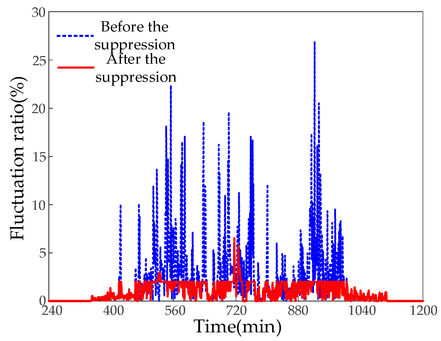
Figure 6 displays the volatility of PV power fluctuations before and after the smoothing. As illustrated in the figure, the maximum volatility of raw PV power is 26.94%, which does not meet the requirements. After smoothing, the PV grid-connected volatility is basically controlled not to exceed 2%, with the maximum being 6.5%. Compared with the original volatility before smoothing, it is reduced by 20.44%, which complies with the PV grid-connected volatility regulations, and the smoothing effect is more prominent.
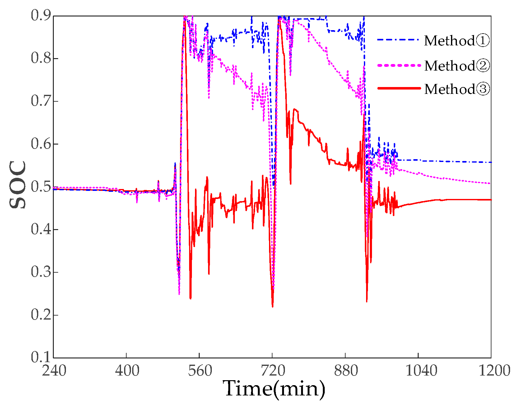
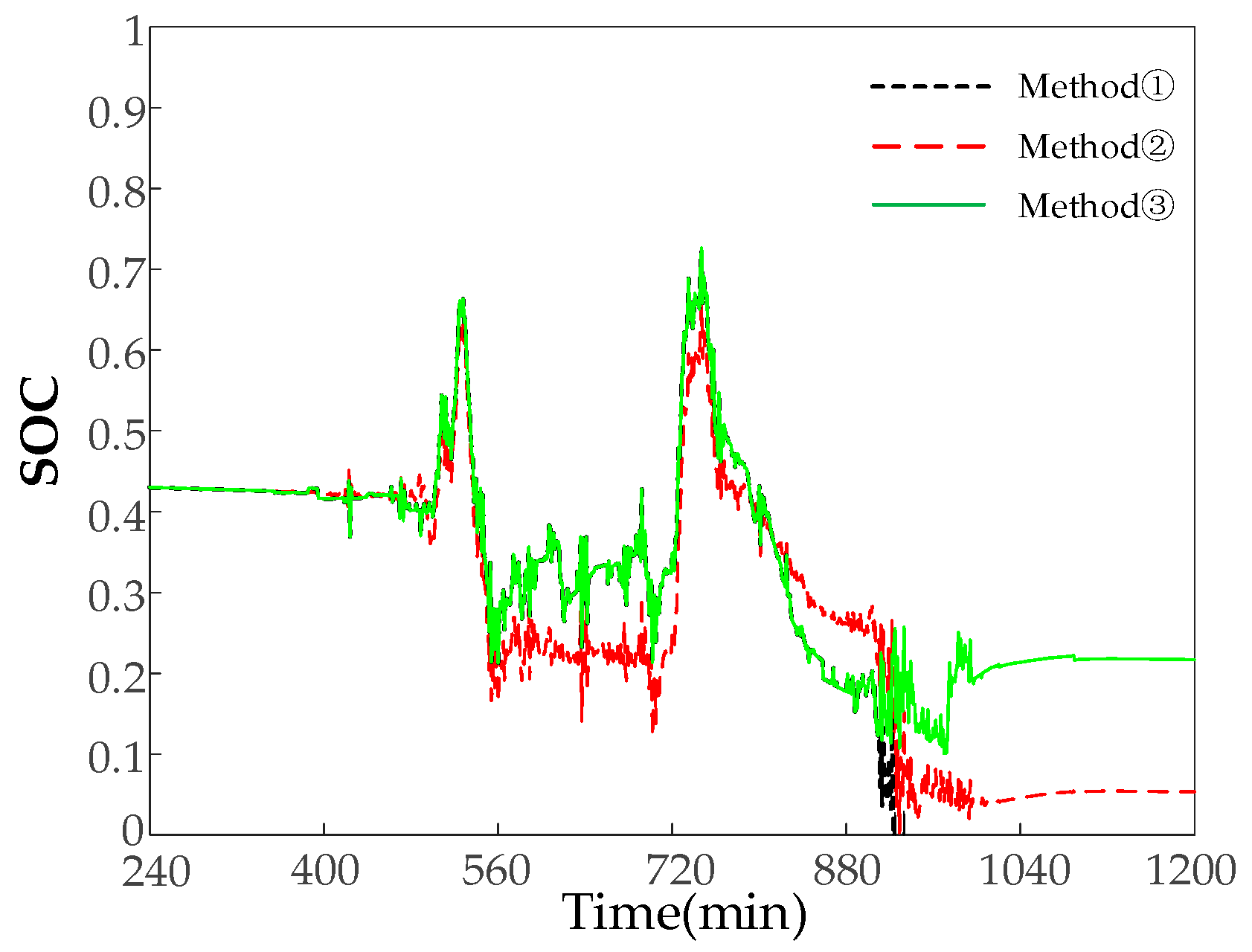
To confirm the function of adaptive model predictive control, comparison experiments are performed on: ① traditional MPC, where only
is considered in the objective function; ② traditional MPC, where
and
are taken into account in the objective function but the weighting coefficients are fixed; and ③ adaptive model predictive control, where
and
are introduced in the objective function on the basis of ②.
Figure 7 shows
in the smoothing process.
Table 2 demonstrates the percentage of
located in the transgressive and healthy intervals in the three methods. After adopting Method ③, the proposed adaptive model predictive control, compared with the traditional Method ①, the time that
is located in the overrun interval in Method ③ is reduced by 351 min, and the time that is located in the [0.4, 0.6] healthy interval is increased by 255 min. Compared with the traditional Method ②, the time that
is located in the overrun interval in Method ③ is reduced by 147 min, and the time that is located in the [0.4, 0.6] healthy interval is increased by 248 min, which shows that the effect of Method ③ is significantly better than that of the two traditional Method ① and Method ②. When
exceeds the limit, this strategy can quickly regulate
back to the normal operating interval, and the time
located in the overcharging/discharging interval is significantly reduced, which protects the energy storage. The percentage of time
located in the [0.4, 0.6] healthy interval is significantly increased, with a more sufficient charging/discharging margin, which strengthens the ability for smoothing future photovoltaic power fluctuations.
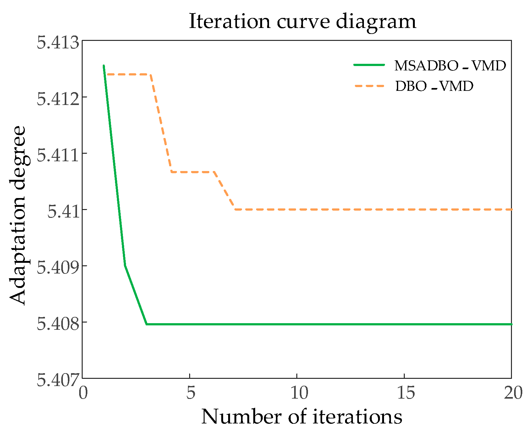
To verify the superiority of MSADBO, MSADBO is compared with DBO, and
Table 3 and
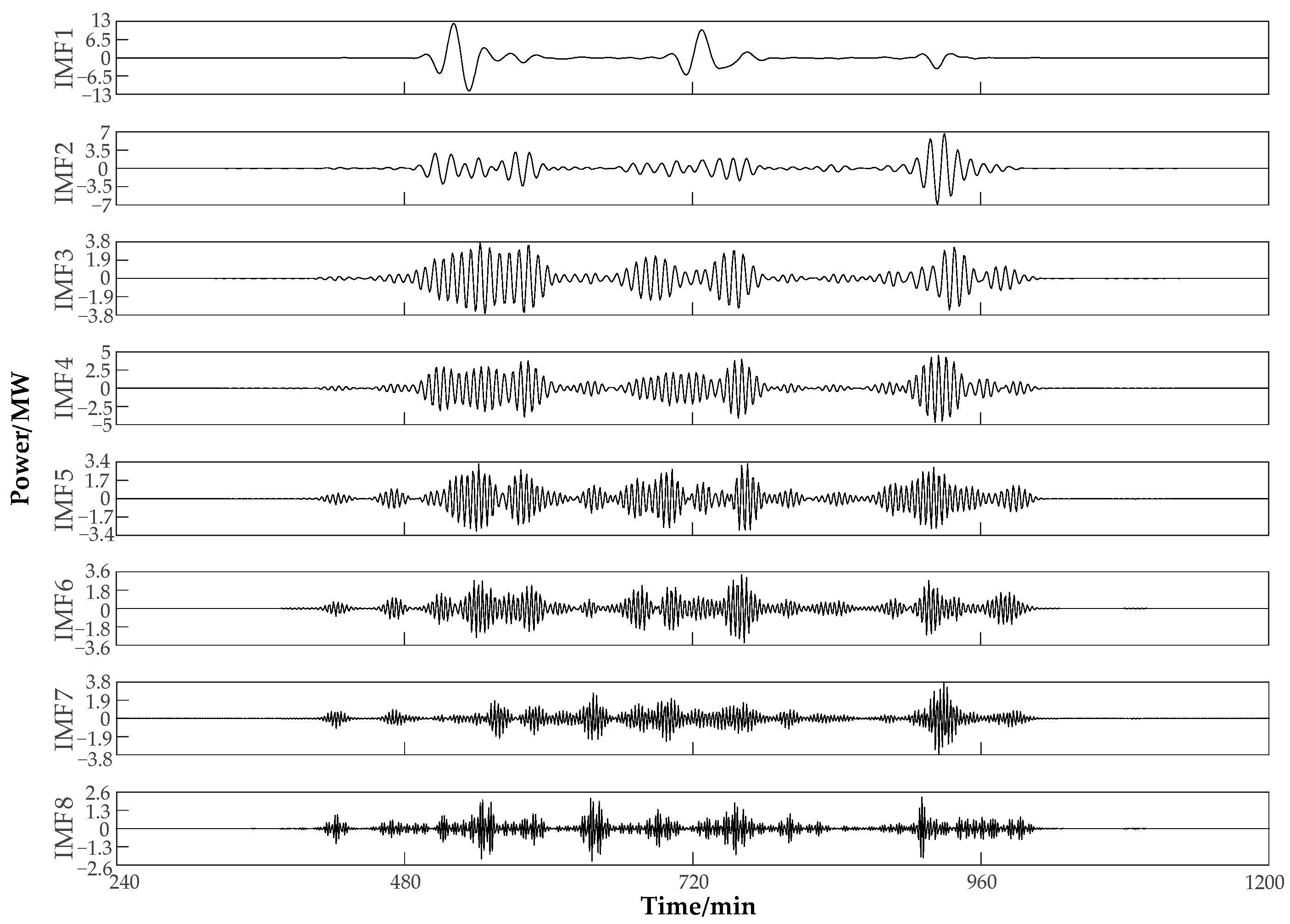
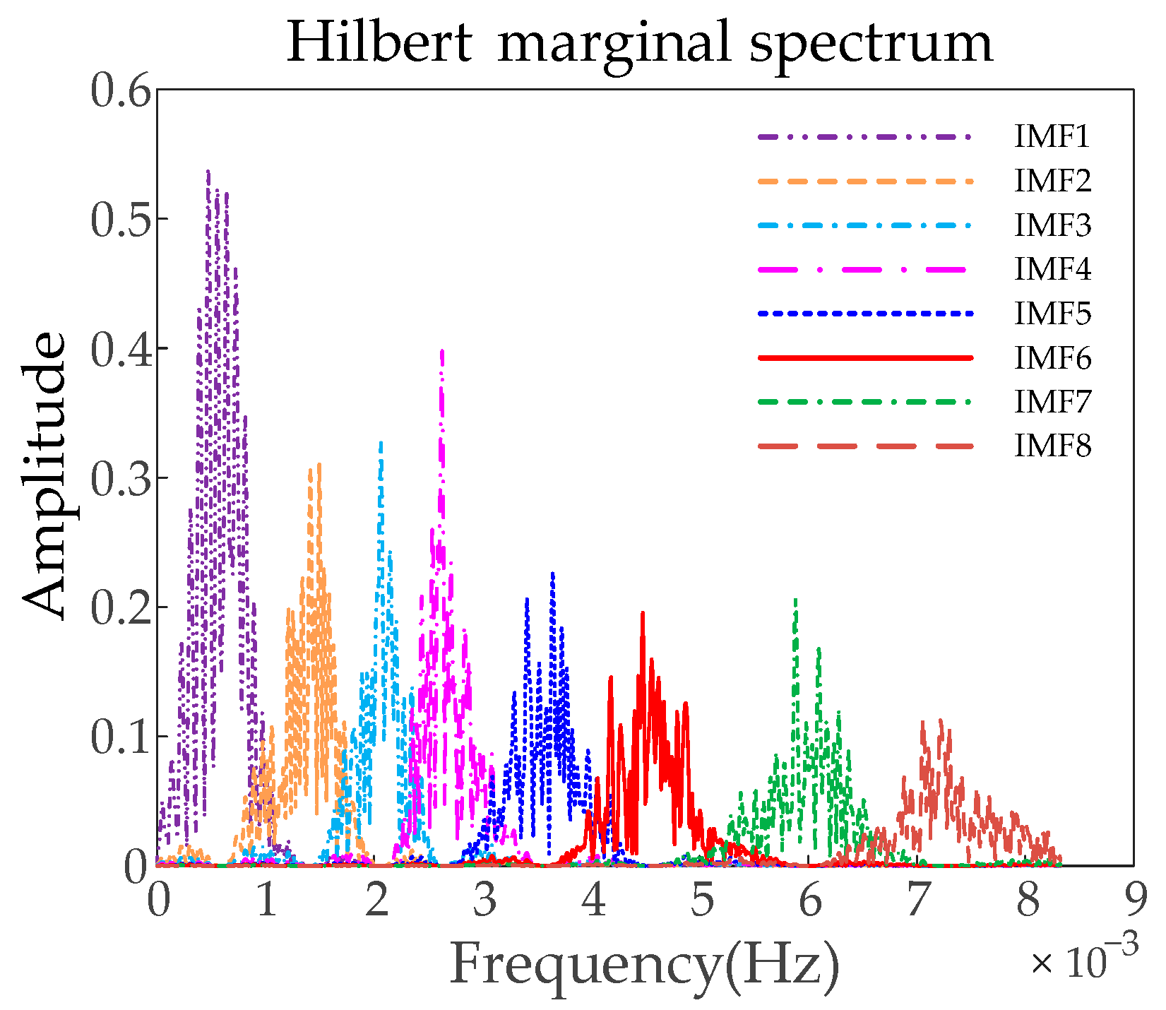
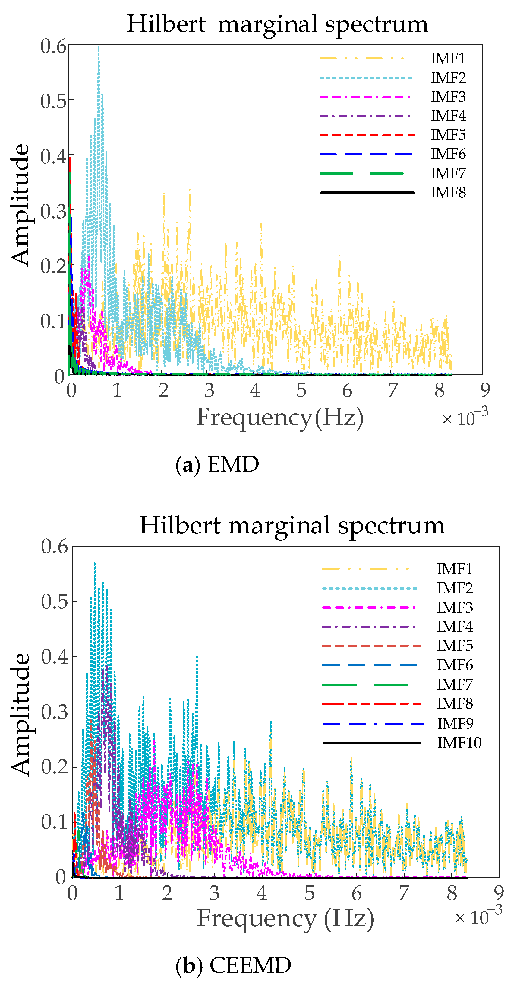
Figure 8 compare the results of the iterations. The optimization speed and accuracy of MSADBO are better than the DBO algorithm, and it is easier to exit local optima. The results of the total power of the HESS after VMD decomposition are shown in
Figure 9. The Hilbert marginal spectra of the MSADBO-VMD, EMD, and CEEMD algorithms are displayed in
Figure 10 and
Figure 11, respectively. It is evident that there is serious modal blending in EMD and CEEMD. Using MSADBO-VMD to decompose the modal distinction is obvious, and it can achieve the reasonable allocation of HESS power.
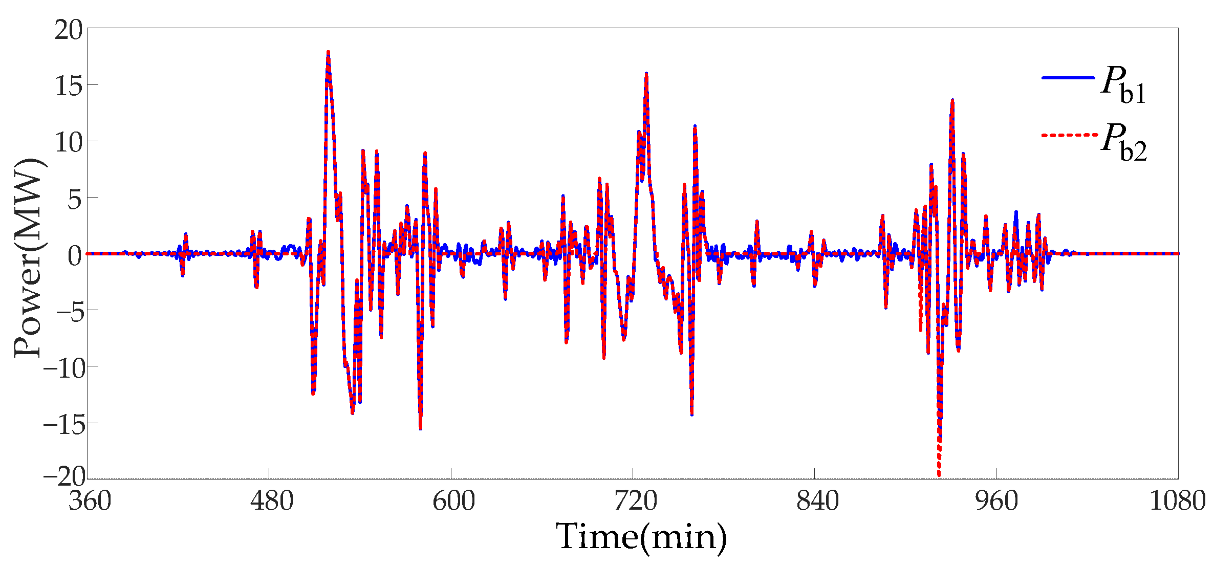
The allocation of power instructions, after the optimization of the charging and discharging times of
Section 4.1, and the optimization of supercapacitor
of
Section 4.2, before and after the optimization of lithium battery power
are compared and shown in
Figure 12. It can be obtained that the number of lithium battery charge/discharge conversions before optimization is 223 times, while the number of lithium battery charge/discharge conversions after optimization is only 77 times, which is 65.47% less than that before optimization. This demonstrates that the proposed strategy can greatly reduce the number of charge/discharge conversions for lithium batteries, which is advantageous for maintaining their longevity.
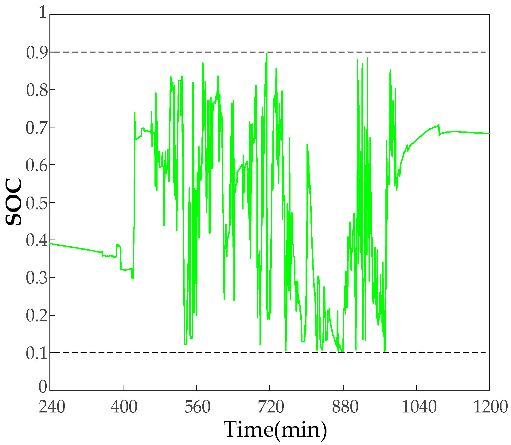
The supercapacitor
in the three cases of ① taking no measures, ② optimizing with traditional fuzzy control, and ③ optimizing with the strategy proposed in
Section 3.2 are compared, as shown in
Figure 13. It can be seen that if no measures are taken,
exceeds the limit at the 911 min mark and drops to 0 at the 923 min mark, losing the ability to participate in smoothing fluctuations. If traditional fuzzy control is used to optimize the supercapacitor
, although the extreme case of
dropping to 0 is avoided, due to the small capacity of the supercapacitor and the random output,
is located in the exceeded interval in the middle of the day for as much as 527 min, accounting for 36.6%, and the expected effect cannot be achieved. If the optimization strategy proposed in this paper is adopted,
has no overrun situation and is able to recover itself in a timely manner.
In order to fully verify the anti-overrun and self-recovery effects of the strategy proposed in
Section 3.2 on
, the capacity of the supercapacitor is significantly reduced to one-fifth of the original, and the optimized
by the proposed strategy is displayed in
Figure 14. It is evident that even in cases where the supercapacitor’s capacity is significantly decreased, the proposed strategy can still ensure that
does not exceed the limit, and the supercapacitor
has a self-recovery effect. At this time, the number of lithium battery charge/discharge conversions only increased by 7.8%, so the strategy will not significantly increase the number of lithium battery charge/discharge conversions.
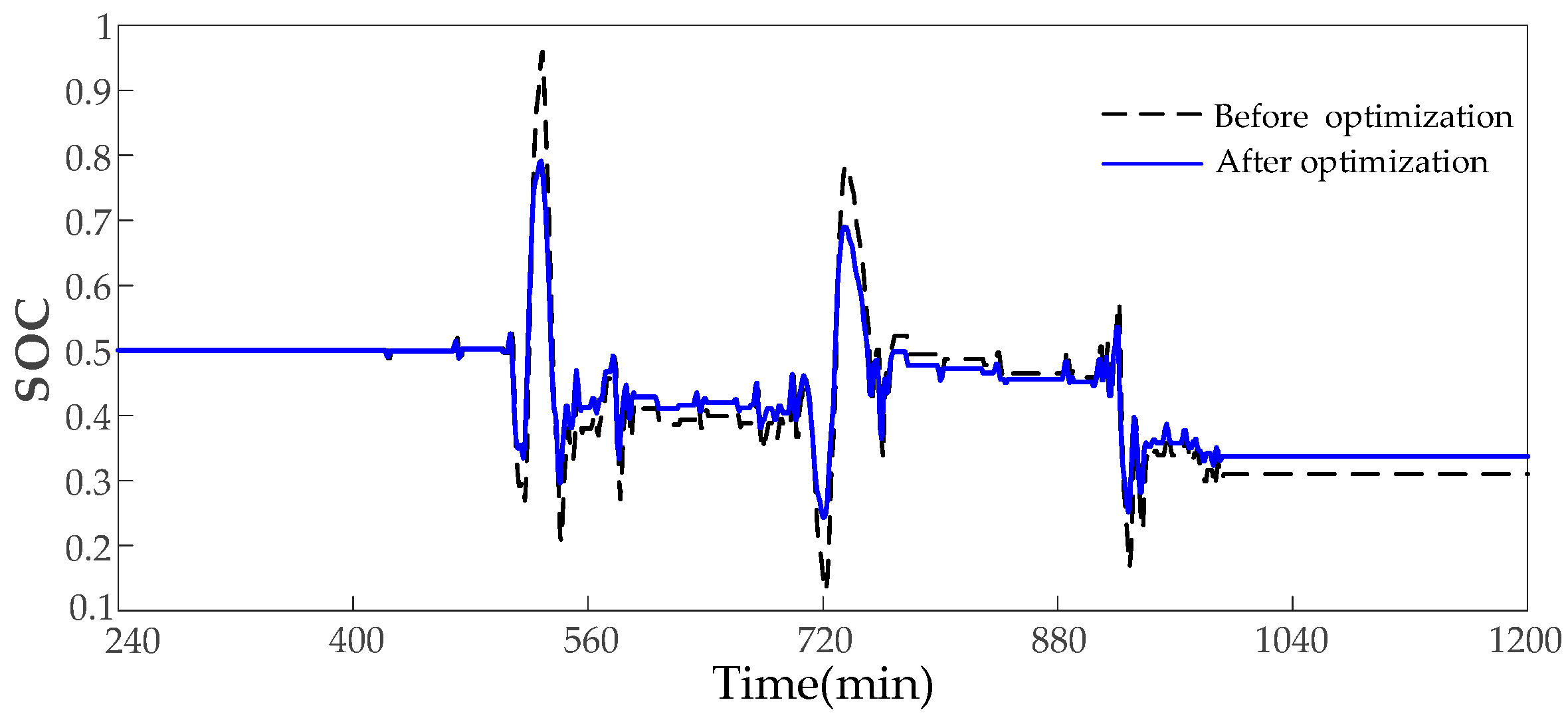
After power optimization of the lithium battery by fuzzy control in
Section 3.3, the
of the lithium battery before and after optimization is shown in
Figure 15. It is evident that after optimization by fuzzy control, the maximum value of
decreased from 95.89% to 79.14%, and the minimum value increased from 13.08% to 24.36%. This shows that
is always located in the normal interval after optimization, preventing the lithium battery
from crossing the limit.
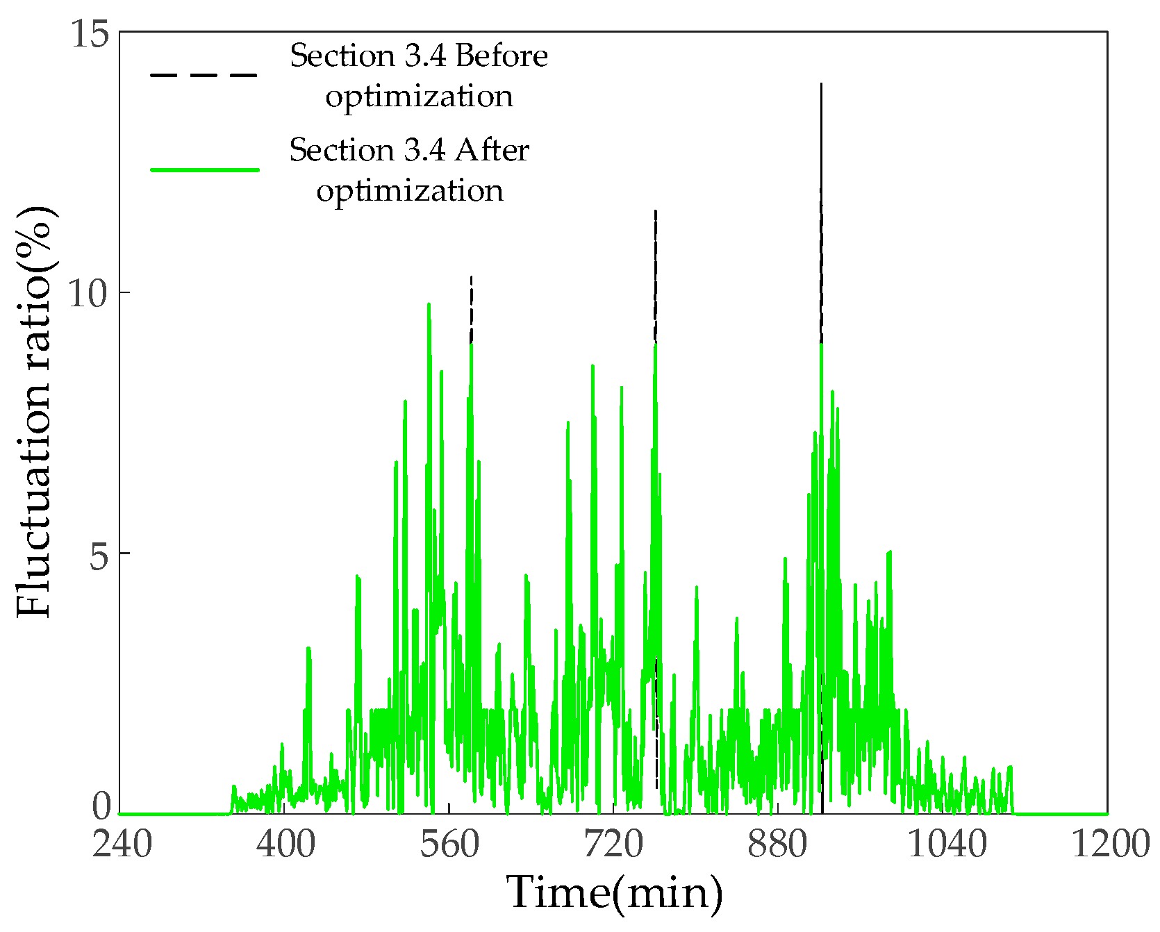
The grid-connected volatility before and after optimization by the mentioned anti-volatility overrun strategy is shown in
Figure 16. It is evident that the grid-connected volatility before optimization has some overruns, reaching a maximum of 14%. After the optimization of the strategy proposed in
Section 3.4, the grid-connected volatility does not overrun, with the highest point being 9.78%, and the requirement of not exceeding 10% is still consistently met. This proves that the proposed strategy can effectively prevent grid-connection volatility from crossing the limit.
