Article

Experimental Study on Heat Transfer Characteristics of Radiant Cooling and Heating

1
College of Emergency Management, Nanjing Tech University, Nanjing 210009, China
2
School of Energy and Environment, Southeast University, Nanjing 210096, China
*
Author to whom correspondence should be addressed.
Energies 2024, 17(13), 3304; https://doi.org/10.3390/en17133304
Submission received: 14 March 2024 / Revised: 7 May 2024 / Accepted: 2 July 2024 / Published: 5 July 2024
(This article belongs to the Section J1: Heat and Mass Transfer)

Abstract

:
While traditional air conditioning systems serve their purpose, radiation air conditioning systems provide several benefits, including improved comfort, higher energy efficiency, and lower initial costs. Nevertheless, the heat exchange capacity per unit area of the radiation plate in such systems is somewhat restricted, which directly affects their practical engineering applications. To address this, experimental investigations were undertaken to examine the impact of cold/hot water supply temperature, water flow velocity, and surface emissivity of radiant panels on their heat transfer characteristics for both summer cooling and winter heating. The findings highlight the significant influence of water supply temperature, flow rate, and surface emissivity on the heat transfer properties of the radiant plates. It is worth noting that adjustments to the water flow rate and surface emissivity impose limitations on enhancing the radiant plate heat transfer performance. For instance, in summer, the heat transfer coefficient of the roughly machined light alumina plate radiant panel was determined by fitting the experimental heat transfer data against characteristic temperatures. Specifically, during cooling, the total heat transfer coefficient of the radiant plate was calculated as 6.77 W/(m2·K), comprising a thermal coefficient of 5.41 W/(m2·K) and a convective heat transfer coefficient of 4.17 W/(m2·K). Conversely, during winter heating, the total heat transfer coefficient of the radiant plate increased to 8.94 W/(m2·K), with a radiation heat transfer coefficient of 6.13 W/(m2·K) and a convective heat transfer coefficient of 3.79 W/(m2·K).

1. Introduction

A radiant air conditioning system represents an energy-efficient, environmentally friendly, and comfortable solution for indoor climate control [1]. Compared to traditional air conditioning systems, radiant air conditioning systems offer superior comfort, energy savings, and enhanced energy utilization [2,3,4]. They excel in peak energy management, enabling year-round operation with a single set of equipment, and require lower initial investment [5], making them a focal point of research in the HVAC (Heating, Ventilation, and Air Conditioning) field in recent years. Despite its numerous advantages over traditional air conditioning, radiation air conditioning does face notable limitations. Chief among these is the relatively small heat transfer capacity per unit area of the radiating plate, necessitating a larger surface area for efficient heat exchange [6]. This limitation directly impacts the practical application of radiation air conditioning systems. To address this challenge and reduce the required surface area, it is imperative to study and improve the heat transfer characteristics of the radiating plate.
Researchers, such as Corina et al. [7], Stetjj [8,9], Oxizidis [10], Zhao [11], and Benjamin [12], among others, have extensively studied the energy efficiency and performance of radiant air conditioning systems. Their findings consistently demonstrate significant energy savings and improved indoor comfort compared to conventional systems, regardless of climate conditions [13,14,15]. Various strategies, including numerical simulations, experimental studies, and innovative control methods, have been proposed to optimize the operation of radiant air conditioning systems and mitigate challenges such as condensation and energy consumption. In particular, advancements in controlling condensation, enhancing indoor comfort, and improving energy efficiency have been a focus of research efforts. Proposed solutions range from pre-desiccating indoor air before system startup [16,17] to intelligent control systems that regulate temperature and humidity [18]. Additionally, investigations into phenomena such as condensation on radiant ceilings [19] and energy consumption comparisons with traditional systems [20] provide valuable insights for system design and optimization. Furthermore, studies by Cholewa and Zhang [21,22], Zhao [23], and Zhang [24] have explored the thermal comfort and energy-saving potential of radiant heating and cooling systems. These investigations underscore the effectiveness of radiant systems in achieving superior energy efficiency and comfort levels, especially when combined with optimized control strategies [25].
The current study focuses on the intrinsic characteristics of radiant plates, aiming to measure the heat transfer properties under different surface emissivity conditions. Experimental setups were designed to investigate the impact of cold/hot water supply temperature, water flow velocity, and surface emissivity on the heat transfer characteristics of radiant panels for both summer cooling and winter heating applications. The results highlight the significant influence of the water supply temperature, flow rate, and surface emissivity on the heat transfer efficiency of radiant plates.

2. Design and Construction of an Experimental System for Radiation Panels

2.1. Purpose and Content of the Experiment

Throughout the experimentation, three distinct materials were utilized to construct the radiant plates: a roughly machined light alumina plate, a white-painted aluminum plate, and a black-painted aluminum plate. These variations were employed to examine the impact of different surface radiation properties on the heat transfer characteristics of the radiant plates. Simultaneously, the influence of varying water supply temperatures and flow rates on the heat transfer properties of the radiant plates was investigated. The experimental variables included the water supply flow rate and temperature. For the summer cooling experiments, the indoor temperature and humidity were maintained at constant levels, while the water supply temperature ranged from 15 °C to 24 °C, and the water supply flow rate varied between 0.1 m/s and 1.0 m/s. Conversely, during the winter heating experiments, consistent indoor temperature and humidity levels were upheld, with the water supply temperature ranging from 28 °C to 42 °C and the water supply flow rate ranging from 0.0 m/s to 1.0 m/s.

2.2. Introduction of Experimental System and Equipment

(1)
Introduction of radiation plate structure
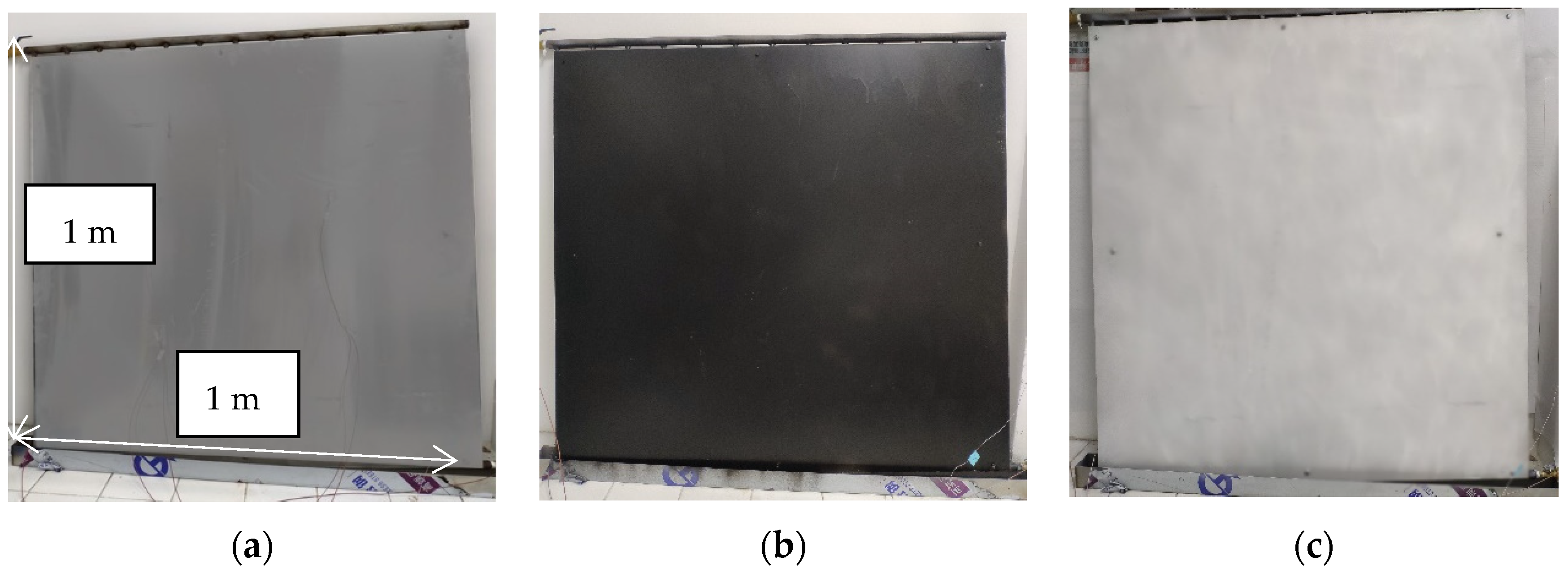
A schematic structure of the radiation plate devised in this study is depicted in Figure 1, while its visual representation is illustrated in Figure 2. Figure 2a–c showcase the radiation plates fabricated from roughly machined light alumina, black spray-painted aluminum, and white spray-painted aluminum surfaces, respectively. The dimensions of the radiant panel measure 1000 mm × 1000 mm × 36 mm and comprise three distinct layers: an insulation layer, a water pipe layer, and a surface layer. As delineated in Figure 1, the radiant plate is arranged sequentially from bottom to top, with the green layer representing the insulation and water pipe layers and the blue layer indicating the surface layer. The insulation layer, crafted from polystyrene, boasts a thermal conductivity of 0.035 W/(m2·K) and a thickness of 20 mm. Its primary function is to confine the direction of heat transfer within the radiant panel, facilitating the transfer of more cooling/heat to the indoor environment while mitigating cooling/heat loss. The water pipes, composed of stainless steel with diameters of 10 mm and 15 mm, are arranged in parallel atop the insulation layer. Featuring a pipe spacing of 75 mm, a main pipe diameter of 15 mm, and a branch pipe diameter of 10 mm, their configuration is depicted in Figure 2a. The surface layer comprises a roughly machined light alumina plate, black spray-painted aluminum plate, and white spray-painted aluminum plate. Aluminum plates exhibit excellent thermal conductivity at 237 W/(m2·K), coupled with an elegant appearance and ease of installation. During experimentation, the radiation plate is affixed to the north wall of the testing chamber and enveloped in low-thermal-conductivity insulation cotton. Only the front side of the radiation plate engages in convective heat transfer with the indoor environment throughout the experiment.
(2)
Cold/hot water circulation system for radiation plate
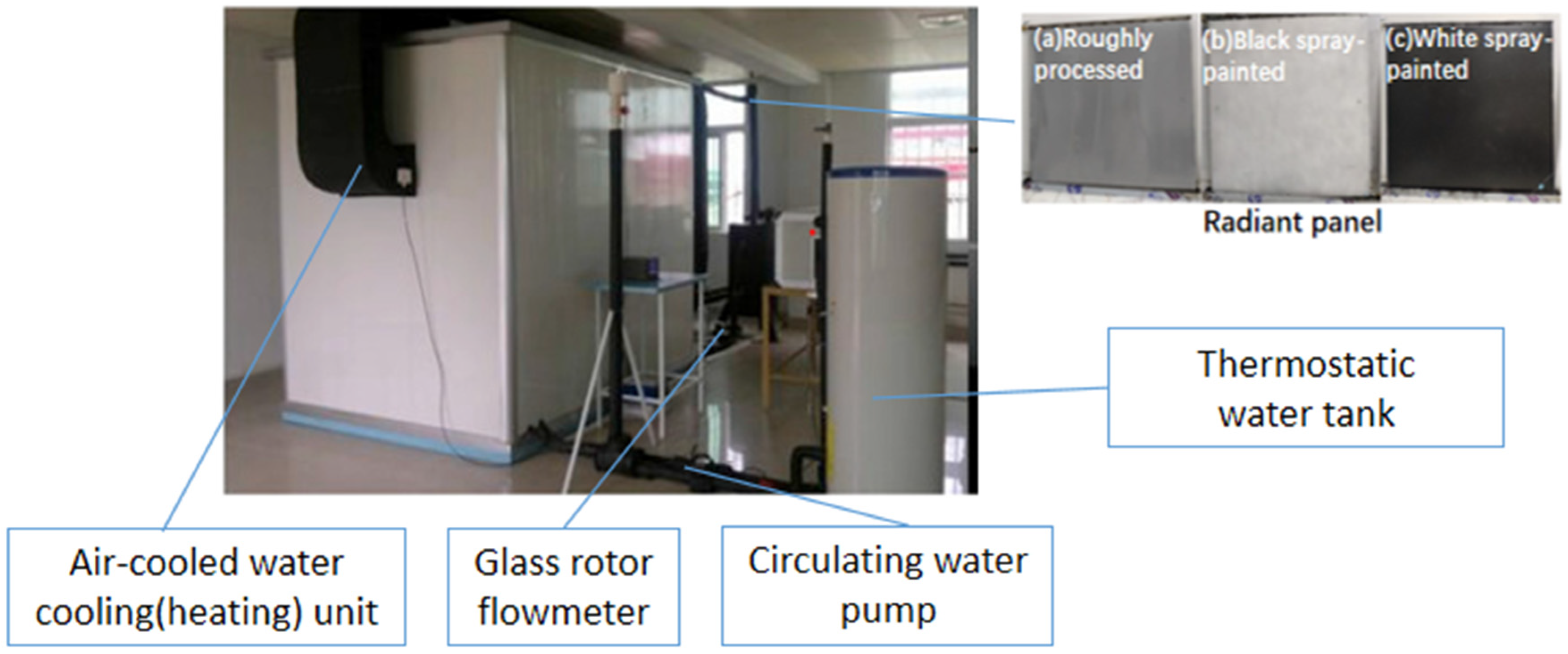
Due to the absence of natural resources conducive to utilizing water-source and ground-source heat pumps in the vicinity of our laboratory, this study employs an air-cooled heat pump as the primary system for generating cold and hot water at the desired temperatures required for experimentation. The experimental setup for investigating the heat transfer characteristics of radiant plate cooling and heating is depicted in Figure 3. The process begins with the cold or hot water generated by the air-cooled heat pump unit, which initially passes through a thermostatic water tank. Subsequently, it is pressurized by a circulating water pump to achieve the necessary pressure and then directed through a glass rotameter to measure the volumetric flow rate of cold or hot water in the pipeline. Finally, the water is transported via a ball valve to the radiant plate installed indoors, after which the cooled or heated water returns to the water tank through the radiant plate. Throughout this circulating process, the pipeline is constructed from PVC plastic hose, with external insulation provided by heat-insulating cotton to minimize heat loss. The air-cooled cold or hot water unit boasts a rated cooling or heating capacity of 5/5.5 kW, with a water flow rate of 0.9 m3/h. The circulating water pump features a power output of 120 W, a rated head of 15 m, and a rated flow rate of 10 L/min. Additionally, the glass rotor flow meter has a diameter of 25 mm and a measuring range of 100–1000 L/h.
In this study, the experimental parameters include temperature, relative humidity, flow rate, cooling capacity, and heating capacity, with the latter two being indirectly calculated parameters. The required measuring equipment for the experiment consists of thermocouples, a digital thermo-hygrometer, a glass rotameter, a stopwatch, and a data acquisition instrument. Temperature and relative humidity within the experimental chamber were monitored using a digital thermo-hygrometer positioned at the room center and 1.2 m above the floor. Four T-type thermocouples were evenly distributed across the surface of the radiant plate to measure its temperature during the experiment, with the average value representing the plate’s surface temperature. Additionally, T-type thermocouples were placed at the center of surfaces of other constructions in the experimental setup, excluding those hosting radiant panels, to monitor temperatures. Two T-type thermocouples were also positioned on the back of the radiant plate, and their average reading was considered as the plate’s rear temperature. T-type thermocouples, also known as copper-constantan thermocouples, have a temperature measurement range of −200 °C to +350 °C. Each thermocouple’s measurement section was covered with aluminum foil and secured with transparent tape. All thermocouples underwent calibration within a temperature range of 0 °C to 40 °C, with satisfactory linear relationships observed. During the experiment, a data acquisition instrument was employed to relay temperature readings from the thermocouples to a computer. The flow rate of cold or hot water passing through the radiant plate was measured using a glass rotameter.
Considering the experimental conditions, temperature measurement range, sensor reliability, measurement accuracy, and cost, T-type thermocouples were selected as temperature sensors. The primary source of error in the experiment stems from measurement inaccuracies relating to temperature and humidity testers and thermocouples. Consequently, separate error analyses were conducted for both. Table 1 outlines the technical specifications of the temperature and humidity tester used. Prior to experimentation, thermocouples underwent calibration to minimize systematic errors arising from production uncertainties. Calibration involved comparing thermocouple readings against those of a mercury thermometer (with 0.1 °C accuracy) in a constant-temperature water bath within a range of 15 °C to 45 °C. The fitting function of the calibration equation is presented below. Additionally, the maximum deviation from the average value did not exceed 8% during individual experiments.
y = a x + b
In the formula, y is the measured value (standard value) of the mercury thermometer; x is the measured value (calibrated value) of the T-type thermocouple. The accuracy of the temperature sensor in measuring temperature is ±0.10 °C, and the lowest temperature measured in the experiment is about 15.5 °C. The relative error of the working medium temperature measurement is as follows:
δ T w a t e r = Δ T T w a t e r = 0.67 %
According to the first law of thermodynamics, the energy equilibrium formula for a radiation plate is as follows:
Q i n Q o u t = m ( h o u t h i n )
From the perspective of cold/hot water supply/heat of the radiation plate, it can be inferred that the thermal balance process of the radiation plate is as follows:
m ( h o u t h i n ) = m w C p ( T f , o u t T f , i n )
In the formula, mw the mass flow rate of cold/hot water, kg/s; Cp is the specific heat capacity at the temperature of cold/hot water supply, kJ/(kg. °C); Tf, in is the temperature of cold/hot water supply, °C; Tf, out is the temperature of the cold/hot water return, °C. The formula can be obtained from the working principle of the radiation plate as follows:
Q i n = 0
Q o u t = Q t o t = Q l o s s + Q r a d + Q c o n
In the formula, Qtot is the total heat transfer of the radiation plate, W; Qloss is the cold/heat loss of the radiation plate, W; Qrad is the radiation heat transfer of the radiation plate, W; Qcon is the convective heat transfer of the radiation plate, W. From the perspective of cold/hot water, the expression for the total heat transfer per unit area of a radiant panel is as follows:
q t o t = m w C p ( T f , o u t T f , i n ) A q l o s s
In the formula, A is the surface area of the radiation plate, m2; Qloss is the unit area loss of cooling/heat of the radiation plate, W/m2. The unit area loss of cold/heat of the radiation plate is mainly the cold/heat loss on the back of the radiation plate, expressed as follows:
q l o s s = k d T d x | b a c k = k ( T 1 T 2 )
In the formula, k is the heat transfer coefficient of the enclosure structure, W/(m2·K); T1 is the temperature on the back of the radiation plate, °C; T2 is the outer surface temperature of the wall where the radiation plate is located, °C. From the perspective of heat exchange between the radiation panel and the indoor environment, it can be seen that the net heat transfer per unit area of the radiation panel is as follows:
q t o t = q r a d + q c o n = h t o t ( T s m T o p )
In the formula, Top is the indoor operating temperature, defined as the weighted average of air dry bulb temperature and average radiation temperature, °C; htot is the total heat transfer coefficient of the radiation plate, composed of radiation heat transfer coefficient and convection heat transfer coefficient, W/(m2·K). The relationship between the total heat transfer per unit area of a radiation plate and the total heat transfer coefficient, convective heat transfer coefficient, and radiative heat transfer coefficient is as follows:
q t o t = h t o t ( T s m T o p ) = h r a d ( A U S T T s m ) + h c o n ( T a T s m )
In the formula, hrad is the radiation heat transfer coefficient of the radiation plate, W/(m2 °C); hcon is the convective heat transfer coefficient of the radiation plate, W/(m2 °C); AUST is the weighted average temperature of indoor surfaces except for radiation panels, in °C. In summary, the energy conservation formula for the entire system is as follows:
m w C p ( T f , o u t T f , i n ) A = h r a d ( A U S T T s m ) + h c o n ( T a T s m ) + k ( T 1 T 2 )
In the above equation, the left side of the equal sign represents the total heat transfer per unit area of the radiation plate, the first item on the right side of the equal sign represents the radiation heat transfer per unit area, the second item represents the convective heat transfer per unit area, and the third item represents the loss of cold/heat per unit area. The unit area radiation heat transfer between the radiation panel and the surface of the indoor non-laid radiation panel is as follows:
q r a d = σ F r ( T s m 4 T r 4 )
In the formula, σ is the Stephen Boltzmann constant, Fr is the radiation heat transfer coefficient, dimensionless. Tsm is the effective temperature on the surface of the cooling (heating) radiation plate, K. Tr is the temperature on the non-cooling and heating surface, K.
T r = j s m n A j ε j T j j s m n A j ε j
In the formula, Aj is the area of all indoor surfaces except for the radiation panel, m2; Tj is the temperature of all indoor surfaces except for the radiation panel, °C; εj is the thermal emissivity of all indoor surfaces except for the radiation panel.

3. Experimental Results of Summer Cooling Heat Transfer Characteristics of the Radiant Plate

3.1. Influence of Cold Water Supply Temperature

The selected radiation plate surface comprises a roughly machined light alumina plate, with the room temperature set at 26 °C and a cold water supply flow rate of 0.7 m/s. Figure 4 illustrates the trend of the radiation plate’s heat exchange characteristics with varying temperatures of the cold water supply, ranging from 15 °C to 24 °C.
From Figure 4, it is evident that the radiation cooling capacity constitutes approximately 65% of the total cooling capacity. With all other experimental conditions held constant, as the temperature of the cold water supply decreases from 24 °C to 15 °C, the cooling capacity per unit area of the radiant plate progressively increases. Specifically, the total cooling capacity rises by 22 W/m2, with the radiation cooling capacity and convection cooling capacity increasing by 15 W/m2 and 7 W/m2, respectively. Consequently, the heat exchanger performance is enhanced. This observation underscores the effectiveness of lowering the cold water supply temperature in augmenting the system’s cooling capacity, with a more pronounced increase in the cooling capacity noted. It is notable that the cold water supply temperature exerts a significant influence on the radiant heat transfer of the radiant panels. After comparing with previous research, it can be found that our radiative cooling system has an improved overall cooling capacity under the same water supply temperature in summer. This is because the radiation cooling plate can better reduce the cooling water temperature

3.2. Influence of Cold Water Supply Flow Rate

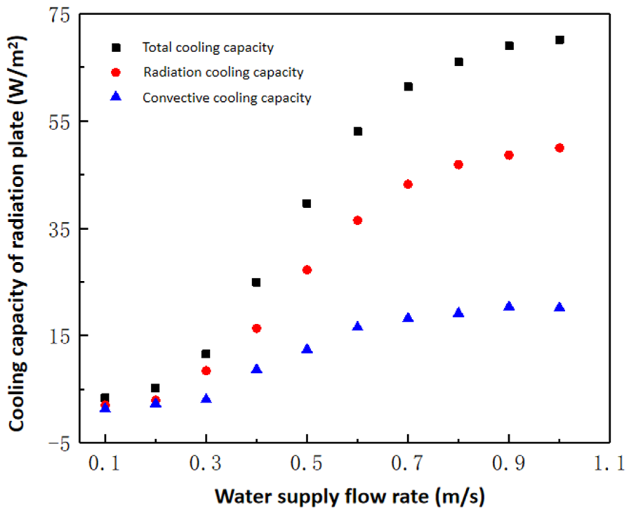
The surface of the selected radiation plate consists of a roughly machined slight alumina plate. The room temperature is maintained at 26 °C, while the cold water supply temperature is set at 17 °C. Figure 5 illustrates the trend of the heat transfer characteristics of the radiation plate with varying flow rates of the cold water supply, ranging from 0.1 m/s to 1.0 m/s.
As depicted in Figure 5, the radiation cooling supply constitutes approximately 65% of the total cooling supply. With all other experimental conditions held constant, the cooling capacity per unit area of the radiant plate exhibits an initial slow increase, followed by a rapid increase, and eventually tends to stabilize with the increase in the cold water supply flow rate. Notably, when the flow rate transitions from 0.1 m/s to 0.3 m/s, the unit area cooling capacity of the radiation plate only increases by 8 W/m2. However, as the flow rate escalates from 0.3 m/s to 0.7 m/s, a significant increase in cooling capacity is observed, with an incremental amount of 50 W/m2. Subsequently, as the flow rate continues to rise, the rate of increase in the cooling capacity gradually flattens out, with only a 10 W/m2 increase noted.
This analysis demonstrates that increasing the flow rate of the cold water supply effectively enhances the cooling capacity of the system, with a more pronounced increase observed in radiation cooling. The flow rate of the cold water supply notably impacts the radiation heat transfer of the radiant plate. However, considering factors such as equipment investment and energy consumption in radiation air conditioning systems, it is observed that beyond a flow rate of 0.7 m/s, further increases offer limited improvements in the heat transfer performance. Moreover, escalating the flow rate results in heightened energy consumption by water pumps and associated transport equipment. Therefore, under the experimental conditions outlined in this section and with the specified form of the radiation plate, the optimal water supply flow rate for summer cooling of radiant panels is determined to be 0.7 m/s.

3.3. Influence of Surface Emissivity on Heat Transfer Characteristics of the Radiant Plate

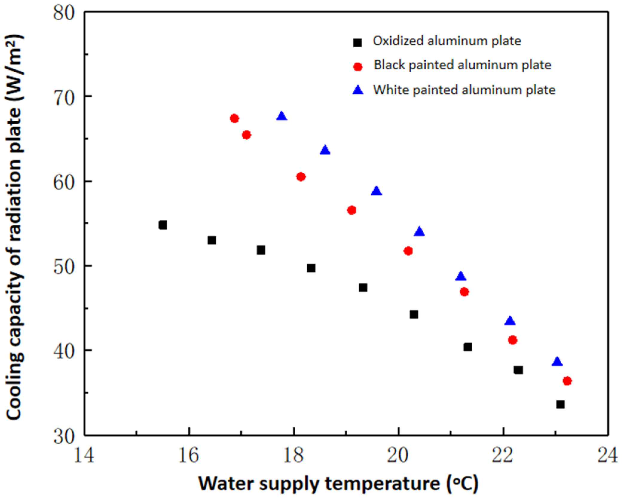
In this study, the primary focus is on the selection of three surface materials for the radiation plate: roughly processed slight alumina plate, black spray-painted aluminum plate, and white spray-painted aluminum plate. The cold water supply rate is set at 0.7 m/s, while the water temperature ranges from 15 °C to 24 °C. Figure 6 illustrates the variations in heat transfer characteristics of the radiation plate with different surface emissivity levels.
As depicted in Figure 6, a higher emissivity of the radiation plate surface correlates with an improved heat transfer performance. Notably, when the cold water supply temperature is elevated, variations in surface emissivity yield minimal changes in cooling capacity. However, as the cold water supply temperature decreases, the influence of surface emissivity becomes more pronounced, resulting in significant fluctuations in cooling capacity. This phenomenon can be attributed to the decrease in the surface temperature of the radiation plate with lower cold water supply temperatures. Surface emissivity plays a pivotal role in radiant heat transfer, and the combination of decreased surface temperature and heightened emissivity enhances heat exchange between the radiation plate and the uncooled surfaces of the room.

3.4. Fitting Analysis of Heat Transfer Coefficient for Summer Cooling of the Radiant Plate

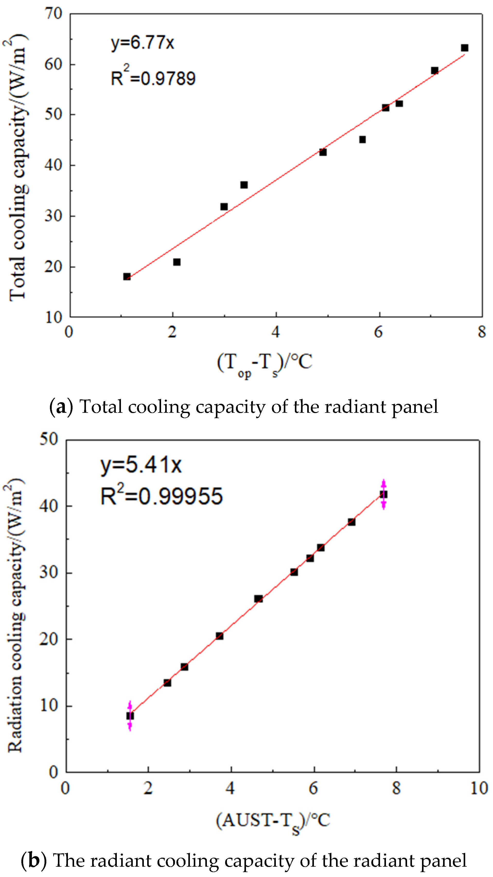
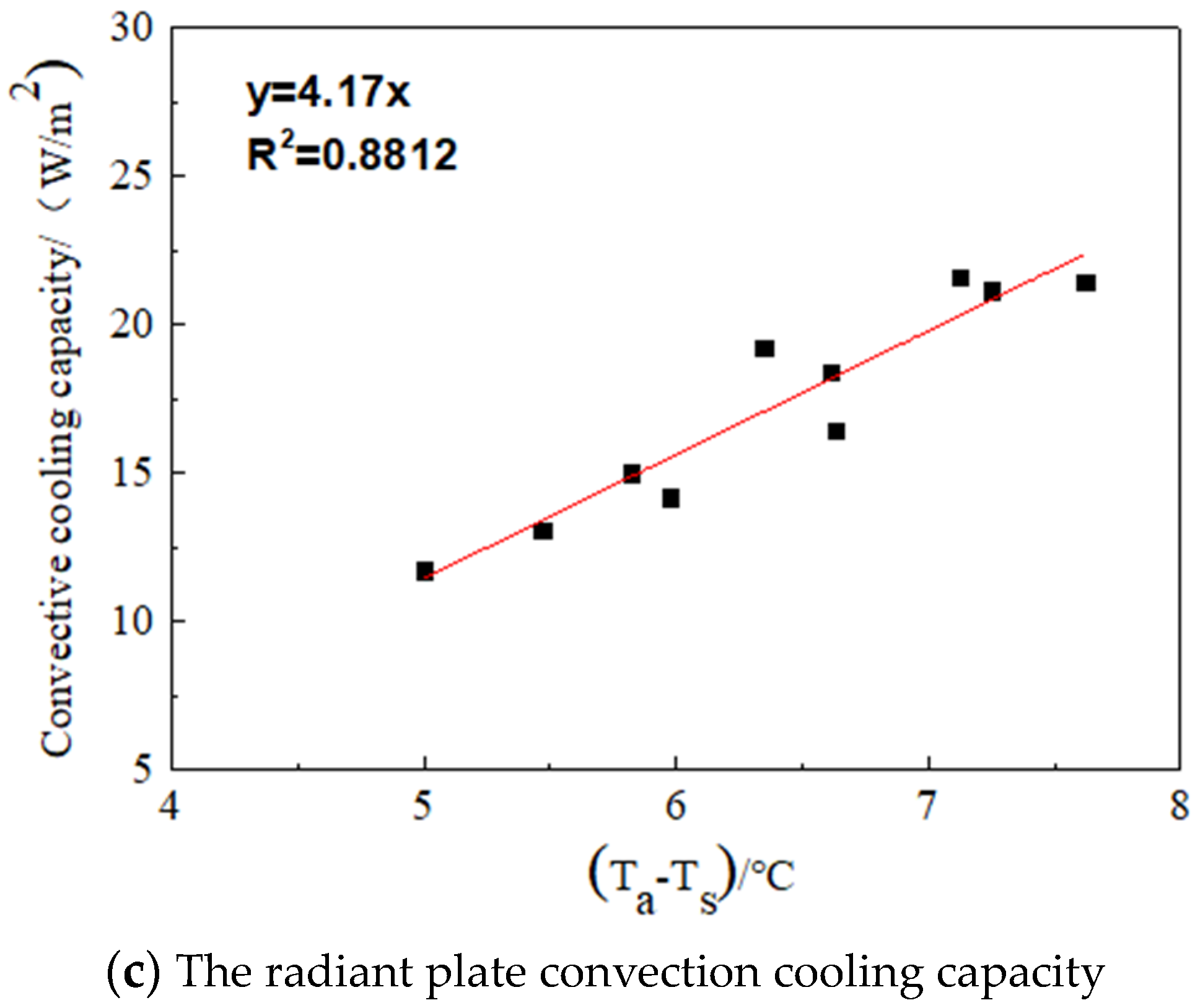
In this section, the heat transfer coefficients of the radiant plate are determined by fitting the cooling supply per unit area of the radiant plate with characteristic temperature differences. Specifically, the total heat transfer coefficient of the radiant plate is derived by fitting the total cooling supply with the temperature difference between the plate’s top surface (Top) and the surrounding air temperature (Ts). Likewise, the radiant heat transfer coefficient is obtained by fitting the amount of radiation cooling with the temperature difference between the ambient uncooled surface temperature (AUST) and Ts, while the convective heat transfer coefficient is acquired by fitting the convective cooling capacity with the temperature difference between the ambient air temperature (Ta) and Ts.
The heat transfer characteristics of the radiant plate and the functional relationship of characteristic temperature differences are presented in Figure 7. The fitting correlation coefficients between the total cooling capacity of the radiant panel and the characteristic temperature difference (Top-Ts), the amount of radiation cooling and the characteristic temperature difference (AUST-Ts), and the convective cooling capacity and the characteristic temperature difference (Ta-Ts) are determined to be 0.9789, 0.99955, and 0.8812, respectively.
Among these, the radiation heat transfer coefficient exhibits a well-fitted curve. This is attributed to the fact that the amount of radiation cooling is calculated using a theoretical model, thus minimizing experimental errors and reducing result uncertainties. Conversely, the convective cooling capacity, derived from the total cooling capacity of the radiant plate and the amount of radiation cooling, is more influenced by experimental errors, leading to higher uncertainties.
Figure 7a displays the fitting curve between the total cooling capacity of the radiant panel and the characteristic temperature difference (Top-Ts), yielding a slope of 6.77. Thus, the total heat transfer coefficient of the radiant plate is determined to be 6.77 W/(m2·K). Similarly, Figure 7b showcases the fitting curve between the amount of radiation cooling and the characteristic temperature difference (AUST-Ts), revealing a slope of 5.41. Consequently, the radiant heat transfer coefficient of the radiant plate is calculated as 5.41 W/(m2·K). Lastly, Figure 7c illustrates the fitting curve between the convective cooling capacity and the characteristic temperature difference (Ta-Ts), with a slope of 4.17. Thus, the convective heat transfer coefficient of the radiant plate is computed as 4.17 W/(m2·K).

4. Experimental Results of Winter Heating Heat Transfer Characteristics of the Radiant Plate

4.1. Influence of Hot Water Supply Temperature

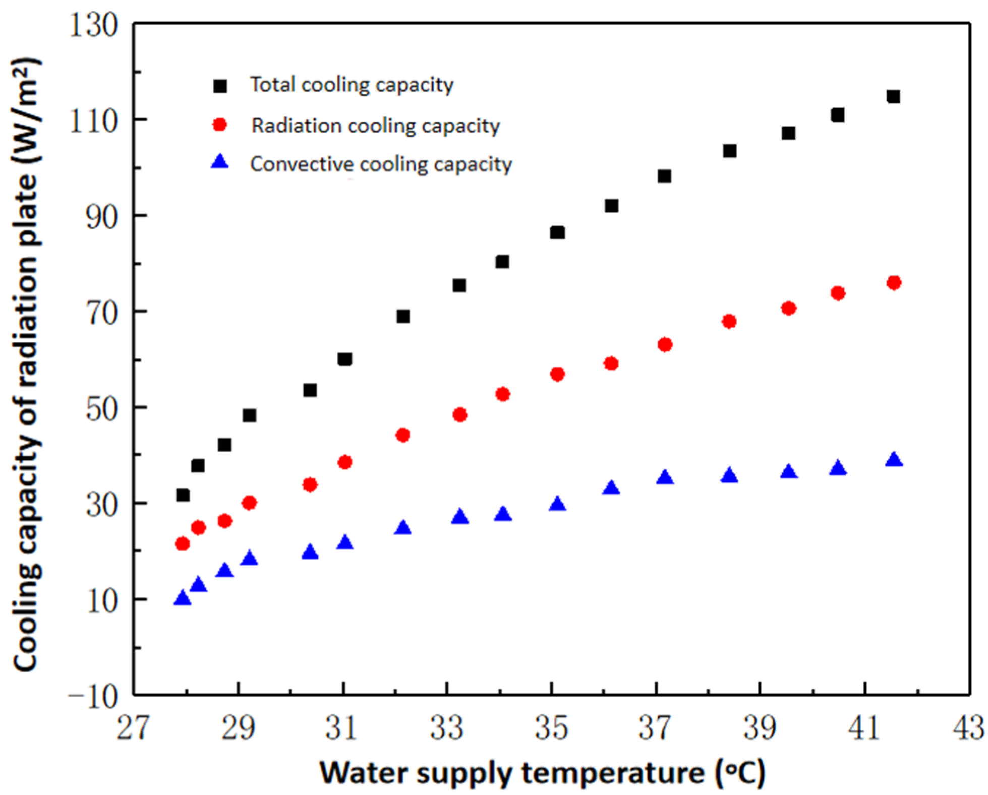
The surface of the chosen radiation plate comprises a roughly processed slight alumina plate. The ambient room temperature is set to 18 °C, while the flow rate of the hot water supply is maintained at 0.7 m/s. The trend of the radiation plate’s heat exchange characteristics with varying temperatures of the hot water supply is depicted in Figure 8, with the hot water supply temperature ranging from 15 °C to 24 °C.
As illustrated in Figure 8, the radiation heat supply constitutes approximately 65% of the total heat supply. With all other experimental conditions held constant, a decrease in the temperature of the hot water supply from 28 °C to 42 °C results in a gradual increase in the heat capacity per unit area of the radiant plate. Specifically, the total heat capacity increases by 83 W/m2, with the radiation heat capacity rising by 53 W/m2 and the convection heat capacity increasing by 30 W/m2. This enhancement leads to an improvement in the heat exchanger performance. It is evident that raising the hot water supply temperature effectively boosts the cooling capacity of the system, with a more pronounced increase observed in radiative heat. Notably, the hot water supply temperature exerts a significant influence on the radiant heat transfer of the panels. Compared with Section 2.1, it is apparent that variations in the water supply temperature to the radiant plate have a substantial impact on the heat transfer performance of the plate under heating conditions.

4.2. The Effect of Hot Water Supply Flow Rate

The selected radiation plate features a roughly processed slight alumina surface. The ambient room temperature is maintained at 18 °C, while the hot water supply temperature is set at 40 °C. The variation in the heat transfer characteristics of the radiation plate with different flow rates of the hot water supply is illustrated in Figure 9, where the hot water supply flow rate ranges from 0.0 m/s to 1.0 m/s.
As depicted in Figure 9, the radiation heat supply constitutes approximately 65% of the total heat supply. Under constant experimental conditions, an increase in the hot water supply flow rate initially leads to a gradual rise in the heat capacity per unit area of the radiant plate, followed by a rapid increase before eventually plateauing. Specifically, when the hot water supply flow rate increases from 0.1 m/s to 0.3 m/s, the heat capacity per unit area of the radiation plate only increases by 10 W/m2. Subsequently, as the flow rate escalates from 0.3 m/s to 0.7 m/s, the heat capacity experiences a significant surge, with an incremental amount of 48 W/m2. However, as the flow rate continues to increase, the rate of heat increase tends to stabilize, with only an 8 W/m2 increase observed.
It is evident that augmenting the flow rate of the hot water supply effectively enhances the heat capacity of the system, with a more pronounced increase in radiation heat. The flow rate of the hot water supply notably influences the radiation heat transfer of the radiant plate. Nevertheless, considering factors such as equipment investment and energy consumption associated with radiation air conditioning systems, it is prudent to acknowledge that beyond a hot water flow rate of 0.7 m/s, the improvement in heat transfer performance becomes limited. Moreover, further increases in the flow rate may lead to heightened energy consumption of water pumps and associated transport equipment. Therefore, under the experimental conditions outlined in this section and considering the radial panel configuration, this conclusion aligns with the findings presented in Section 2.2 regarding optimal flow rates for summer cooling.

4.3. The Effect of Surface Emissivity

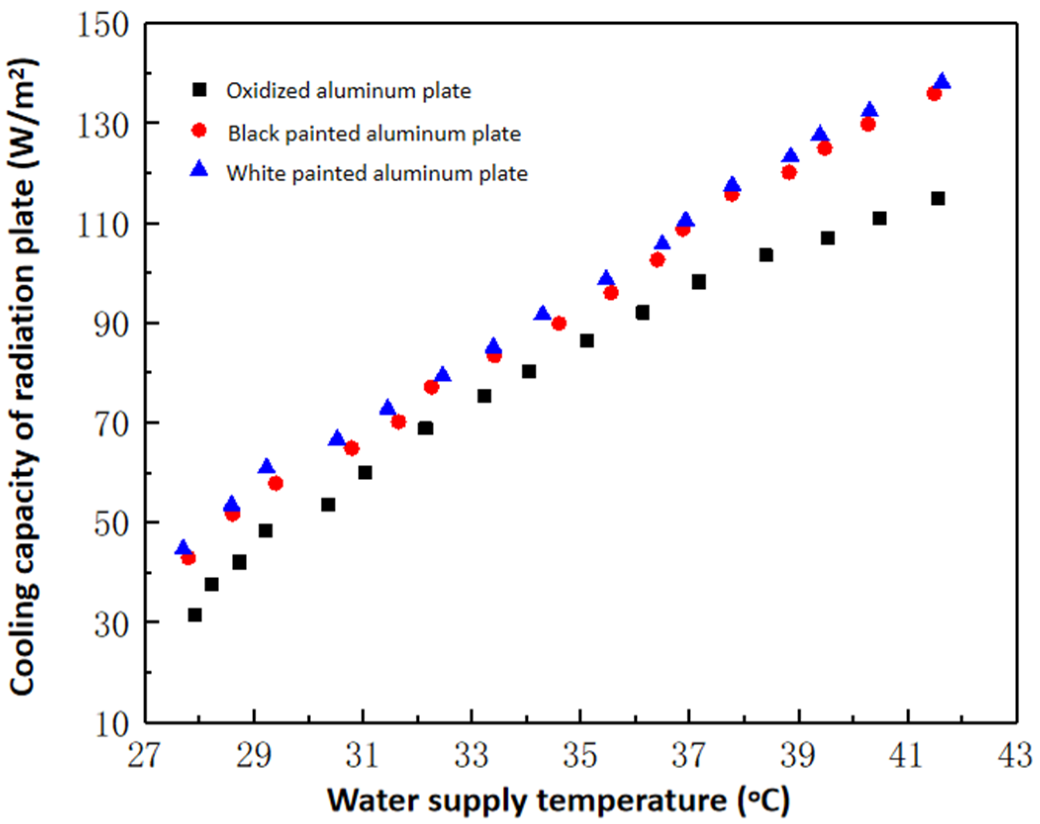
This section focuses on the selection of surface materials for the radiation plate, including rough processed slightly oxidized aluminum plates, black-painted aluminum plates, and white-painted aluminum plates. The water supply flow rate is maintained at 0.7 m/s, while the water supply temperature ranges from 26 °C to 42 °C. Figure 10 illustrates the variation in the heat transfer characteristics of the radiation plate corresponding to different emissivities of its surface.
As depicted in Figure 10, higher surface emissivity correlates with an enhanced heat transfer performance of the radiation plate. Notably, when the hot water supply temperature is low and the surface emissivity varies, the change in heating capacity is minimal. However, with higher hot water supply temperatures and varying surface emissivities, the fluctuations in heating capacity become more pronounced. This phenomenon can be attributed to the gradual increase in the surface temperature of the radiation plate as the hot water supply temperature rises. The surface emissivity plays a significant role in radiation heat transfer, and the combined effect of elevated surface temperature and emissivity enhances the heat exchange between the radiation plate and the unheated indoor surfaces. Consequently, this leads to an effective improvement in the heat transfer performance of the radiation plate.

4.4. Fitting Analysis of Heat Transfer Coefficient of the Radiant Plate for Winter Heating

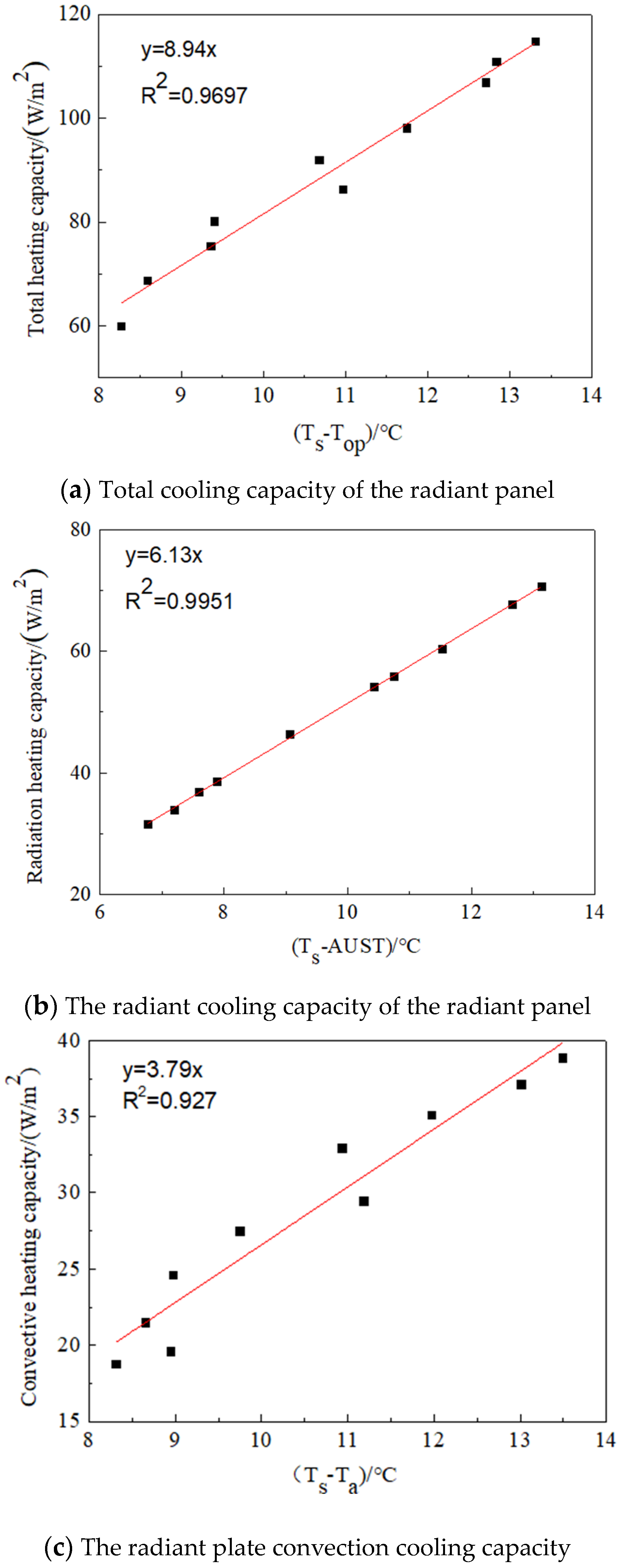
The heat transfer coefficient of the radiant plate is determined by fitting the heat supply per unit area of the radiant plate with the characteristic temperature difference. The heat transfer characteristics and the functional relationship of the characteristic temperature difference are presented in Figure 11. The fitting correlation coefficients between the total heat capacity of the radiant panel and the characteristic temperature difference (Top-Ts), the amount of radiation heat and the characteristic temperature difference (AUST-Ts), and the convective heat capacity and the characteristic temperature difference (Ta-Ts) are 0.9697, 0.9951, and 0.927 respectively.
Among these, the radiation heat transfer coefficient exhibits the best fit. This can be attributed to the fact that the amount of radiation heat is determined by a theoretical model, resulting in minimal experimental error and uncertainty in the results. Conversely, the fitting degree of the convective heat transfer coefficient is the lowest. This is because the convective heat capacity is calculated based on the total heat capacity of the radiant plate and the amount of radiation heat, leading to a larger impact of the experimental error and higher uncertainty.
Figure 11a illustrates the fitting curve between the total heat capacity of the radiant panel and the characteristic temperature difference (Top-Ts). The slope of the curve, obtained as 8.94, indicates that the total heat transfer coefficient of the radiant plate is 8.94 W/(m2·K). Figure 11b depicts the fitting curve between the amount of radiation heat and the characteristic temperature difference (AUST-Ts), revealing a slope of 6.13. Consequently, the radiant heat transfer coefficient of the radiant plate is determined to be 6.13 W/(m2·K). Lastly, Figure 11c displays the fitting curve between the convective heat capacity and the characteristic temperature difference (Ta-Ts), with a slope of 3.79. Therefore, the convection heat transfer coefficient of the radiant plate is calculated to be 3.79 W/(m2·K).

5. Conclusions

This section investigates the effects of the cold/hot water supply temperature, supply flow rate, and radiation plate surface emissivity on the heat transfer characteristics of radiation plates during summer cooling and winter heating through experiments. The surface materials of radiation plates are rough slightly oxidized aluminum plates, black spray-painted aluminum plates, and white spray-painted aluminum plates. By analyzing the experimental results, the following conclusions can be drawn:
(1) When the radiation plate is used for cooling in summer, reducing the cold water supply temperature can improve the heat transfer performance of the radiation plate, and the improvement in radiation heat transfer performance is more significant. By increasing the flow rate of the cold water supply, the cooling capacity per unit area of the radiation plate first slowly increases, then rapidly increases, and finally tends to stabilize. Moreover, improving the surface emissivity of radiation panels can effectively enhance their heat transfer performance, and the increase in the radiation cooling capacity is significant.
(2) When using radiant panels for winter heating, the improvement in the heat transfer performance can be attributed to the increase in the hot water supply temperature, and the improvement in the radiant heat transfer performance is more significant. Raising the temperature of the hot water supply, increasing the flow rate of the water supply, and increasing the surface emissivity of the radiation plate can effectively enhance the heat transfer performance of the radiation plate and have a significant impact on radiation heat transfer.
(3) By fitting the unit area heat transfer and characteristic temperature difference of the radiant panel for summer cooling and winter heating, the heat transfer coefficient of the radiant panel is obtained: during summer cooling, the total heat transfer coefficient of the radiant panel is 6.77 W/(m2·K), the radiation heat transfer coefficient is 5.41 W/(m2·K), and the convective heat transfer coefficient is 4.17 W/(m2·K); during winter heating, the total heat transfer coefficient of the radiant panel is 8.94 W/(m2·K), the radiation heat transfer coefficient is 6.13 W/(m2·K), and the convection heat transfer coefficient is 3.79 W/(m2·K). The results of this study could help to reduce the energy consumption of winter heating and summer cooling in buildings.

Author Contributions

Methodology, S.C.; Validation, X.M.; Resources, C.H. All authors have read and agreed to the published version of the manuscript.

Funding

This work was supported by the National Natural Science Foundation of China (No. 52306090, No. 52076040) and China Postdoctoral Science Foundation (Grant No. 2023M731642).

Data Availability Statement

The original contributions presented in the study are included in the article, further inquiries can be directed to the corresponding author.

Acknowledgments

We would like to thank Xu Bo and Shi Juan for their guidance and assistance in this article.

Conflicts of Interest

The authors declare no conflict of interest.

Nomenclature

Symbols
Q Heat production (W)
m Mass flow rate (kg/s)
T Temperature (K)
h Convective heat transfer coefficient (W/(m2·K))
k Thermal conductivity coefficient (W/(m·K))
F Radiation heat transfer coefficient (W/(m2·K))
Greek alphabet
σ Stephen Boltzmann constant
Abbreviation
RHRelative humidity
AUSTAmbient uncooled surface temperature

References

  1. Almahmoud, S.; Jouhara, H. Experimental and theoretical investigation on a radiative flat heat pipe heat exchanger. Energy 2019, 174, 972–984. [Google Scholar] [CrossRef]
  2. Chen, Q.; Wang, J.; Gao, M.; Liu, L.; Tao, J. Review on loss prevention of chemical reaction thermal runaway: Principles and application. Emerg. Manag. Sci. Technol. 2022, 2, 10. [Google Scholar] [CrossRef]
  3. Yang, F.; Shao, C. Study on cavitation of liquid nitrogen in pumps induced by coupling of pressure drop and external temperature. Emerg. Manag. Sci. Technol. 2022, 2, 18. [Google Scholar] [CrossRef]
  4. Arata, S.; Kawakubo, S. Study on productivity of office workers and power consumption of air conditioners in a mixed-mode ventilation building during springtime. Build. Environ. 2022, 214, 108923. [Google Scholar] [CrossRef]
  5. Xing, D.M.; Li, N.P.; Zhang, C.; Heiselberg, P. A critical review of passive condensation prevention for radiant cooling. Build. Environ. 2021, 205, 108230. [Google Scholar] [CrossRef]
  6. Guo, Y.L.; Wu, H.J.; Du, K.; Huang, G.S.; Xu, X.H. Experimental study on radiant cooling with double-skin infrared-transparent membranes. Energy Build. 2022, 278, 112654. [Google Scholar] [CrossRef]
  7. Stetiu, C. Energy and peak power savings potential of radiant cooling systems in US commercial buildings. Energy Build. 1999, 30, 127–138. [Google Scholar] [CrossRef]
  8. Kim, T.; Kato, S.; Murakami, S. Indoor cooling/heating load analysis based on coupled simulation of convection, radiation and HVAC control. Build. Environ. 2001, 36, 901–908. [Google Scholar] [CrossRef]
  9. Murakami, S.; Kato, S.; Kim, T. Coupled simulation of convection, radiation, and HVAC control for attaining a given PMV value. Build. Environ. 2001, 36, 701–709. [Google Scholar] [CrossRef]
  10. Oxizidis, S.; Papadopoulos, A.M. Performance of radiant cooling surfaces with respect to energy consumption and thermal comfort. Energy Build. 2013, 57, 199–209. [Google Scholar] [CrossRef]
  11. Zhao, K.; Liu, X.H.; Jiang, Y. Application of radiant floor cooling in a large open space building with high-intensity solar radiation. Energy Build. 2013, 66, 246–257. [Google Scholar] [CrossRef]
  12. Behrendt, B. Experimental Study of Indoor Environmental Quality and Energy Use by Different Combinations of Heating, Cooling and Ventilation Systems. Master’s Thesis, Technical University of Denmark, Kongens Lyngby, Denmark, 2010. [Google Scholar]
  13. Ferrara, M.; Peretti, C.; Fabrizio, E.; Corgnati, S.P. On the Multi-Domain Impacts of Coupling Mechanical Ventilation to Radiant Systems in Residential Buildings. Energies 2023, 16, 4870. [Google Scholar] [CrossRef]
  14. Xing, D.M.; Li, N.P. Reconstruction of hydronic radiant cooling panels: Conceptual design and numerical simulation. Therm. Sci. Eng. Prog. 2022, 30, 101272. [Google Scholar] [CrossRef]
  15. Zhou, X.; Liu, Y.L.; Zhang, J.S.; Ye, L.F.; Luo, M.H. Radiant asymmetric thermal comfort evaluation for floor cooling system-A field study in office building. Energy Build. 2022, 260, 111917. [Google Scholar] [CrossRef]
  16. Dharmasastha, K.; Zhong, Z.W.; Niu, J.L.; Liang, H.B. A comprehensive review of cover-shield-assisted radiant cooling system. Energy Build. 2023, 291, 113121. [Google Scholar] [CrossRef]
  17. Liang, H.B.; Liu, L.; Zhong, Z.W.; Gan, Y.X.; Wu, J.Y.; Niu, J.L. Towards idealized thermal stratification in a novel phase change emulsion storage tank. Appl. Energy 2022, 310, 118526. [Google Scholar] [CrossRef]
  18. Mumma, S.A.; Jeong, J.W. Direct digital temperature, humidity and condensate control for a dedicated outdoor air-ceiling radiant cooling panel system. ASHRAE Trans. 2005, 111, 547–558. [Google Scholar]
  19. Tang, H.; Liu, X.H. Experimental study of dew formation on metal radiant panels. Energy Build. 2014, 85, 515–523. [Google Scholar] [CrossRef]
  20. Barrios, G.; Huelsz, G.; Rojas, J. Thermal performance of envelope wall/roofs of intermittent air-conditioned rooms. Appl. Therm. Eng. 2012, 40, 1–7. [Google Scholar] [CrossRef]
  21. Cholewa, T.; Rosinski, M.; Spik, Z.; Dudzinska, M.R.; Siuta-Olcha, A. On the heat transfer coefficients between heated/cooled radiant floor and room. Energy Build. 2013, 66, 599–606. [Google Scholar] [CrossRef]
  22. Zhang, D.K.; Li, C.; Li, Z.R. Experimental study on performance of different local radiant cooling schemes. Int. J. Refrig. 2023, 151, 241–252. [Google Scholar] [CrossRef]
  23. Zhao, K.; Liu, X.H.; Jiang, Y. Dynamic performance of water-based radiant floors during start-up and high-intensity solar radiation. Sol. Energy. 2014, 101, 232–244. [Google Scholar] [CrossRef]
  24. Zhang, L.; Liu, X.H.; Jiang, Y. Simplified calculation for cooling/heating capacity, surface temperature distribution of radiant floor. Energy Build. 2012, 55, 397–404. [Google Scholar] [CrossRef]
  25. Koca, A.; Gemici, Z.; Topacoglu, Y.; Cetin, G.; Acet, R.C.; Kanbur, B.B. Experimental investigation of heat transfer coefficients between hydronic radiant heated wall and room. Energy Build. 2014, 82, 211–221. [Google Scholar] [CrossRef]
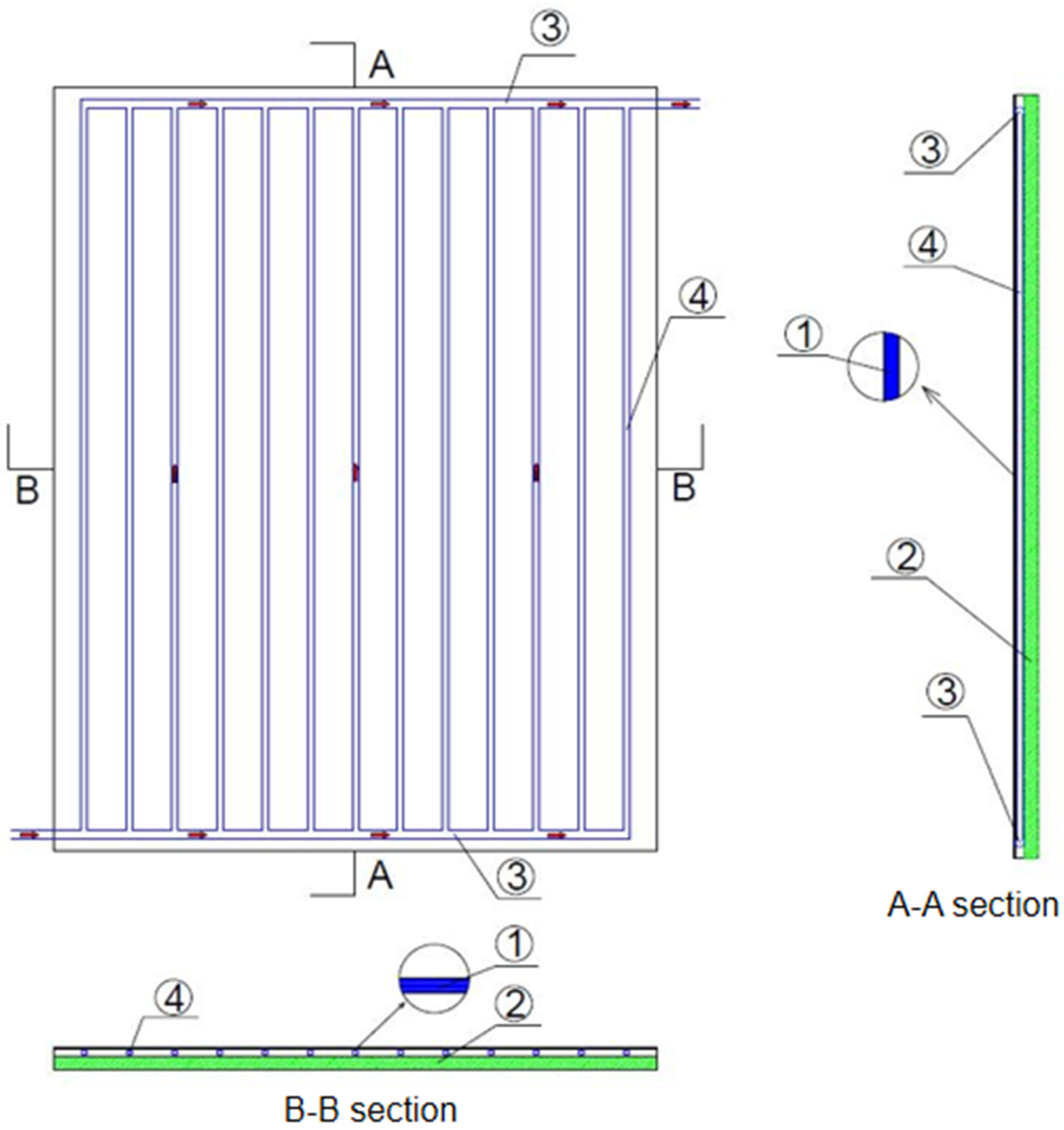
Figure 1. Schematic diagram of the radiant plate structure. 1—surface layer; 2—insulation layer; 3—main pipe; 4—branch pipe.
Energies 17 03304 g001
Figure 2. Appearance of the radiant panel. (a) roughly processed slight alumina plate, (b) black spray-painted surface aluminum plate, (c) white spray-painted surface aluminum plate.
Energies 17 03304 g002
Figure 3. Overview of the experimental monitoring system.
Energies 17 03304 g003
Figure 4. Influence of different cold water supply temperatures on heat transfer characteristics of the radiant plate [25].
Energies 17 03304 g004
Figure 5. Influence of different flow rates of cold water supply on the heat transfer characteristics of the radiant panels.
Energies 17 03304 g005
Figure 6. Influence of different surface emissivity values on heat transfer characteristics of the radiant plate in summer.
Energies 17 03304 g006
Figure 7. Diagram of the radiant plate heat transfer characteristics in summer (Arrow in the figure refer to the temperature range).
Energies 17 03304 g007aEnergies 17 03304 g007b
Figure 8. Influence of different hot water supply temperatures on heat transfer characteristics of the radiant plate.
Energies 17 03304 g008
Figure 9. Influence of different hot water supply flow rates on the heat transfer characteristics of the radiant panels.
Energies 17 03304 g009
Figure 10. Influence of different surface emissivity on heat transfer characteristics of the radiant plate in winter.
Energies 17 03304 g010
Figure 11. Diagram of the radiant plate heat transfer characteristics in winter.
Energies 17 03304 g011
Table 1. Technical parameters of temperature and humidity tester.
Measuring RangeHumidity RangeTemperature
Measurement Error
Humidity Measurement ErrorResolving PowerProduct Size
°C%RH°C%RH°C/%RHmm
−20–10005–98±1.5±5 (5–40)/±4 (41–80)0.1/0.1156 × 66 × 33
Disclaimer/Publisher’s Note: The statements, opinions and data contained in all publications are solely those of the individual author(s) and contributor(s) and not of MDPI and/or the editor(s). MDPI and/or the editor(s) disclaim responsibility for any injury to people or property resulting from any ideas, methods, instructions or products referred to in the content.