Article

The Feasibility of Heat Extraction Using CO2 in the Carbonate Reservoir in Shandong Province, China

by
Xiao Liu
1,2,
Feng Zhang
1,2,
Shuailiang Song
1,2,
Xianfeng Tan
1,2,* and
Guanhong Feng
3,*
1
Shandong Provincial Lunan Geo-Engineering Exploration Institute (Shandong Provincial Bureau of Geology and Mineral Resources No. 2 Geological Brigade), Jining 272100, China
2
Shandong Engineering Research Center of Geothermal Energy Exploration and Development, Jining 272100, China
3
Key Laboratory of Groundwater Resources and Environment, Ministry of Education, Jilin University, Changchun 130021, China
*
Authors to whom correspondence should be addressed.
Energies 2024, 17(12), 2910; https://doi.org/10.3390/en17122910
Submission received: 17 December 2023 / Revised: 12 January 2024 / Accepted: 17 January 2024 / Published: 13 June 2024
(This article belongs to the Special Issue The Status and Development Trend of Geothermal Resources)

Abstract

:
CO2 is being considered as an effective alternative working fluid for geothermal applications due to its superior fluid dynamics and heat transfer properties compared to water. Utilizing sedimentary rocks for geothermal energy recovery through a CO2-plume geothermal system, especially in carbonate reservoirs, has been shown to be a practical approach that eliminates the need for hydraulic fracturing. However, uncertainties remain regarding the thermal and hydraulic behavior, particularly the chemical interactions between CO2 and carbonate rocks. This study develops a comprehensive wellbore–reservoir coupling reactive transport model based on specific information obtained from the Ordovician limestone geothermal reservoir in Shandong, China. The model aims to assess the feasibility of heat extraction in carbonate reservoirs by evaluating the heat extraction performance and fluid–rock interaction. The results indicate a rapid temperature drop after CO2 breakthrough due to the Joule–Thomson effect. Simultaneously, the fluid transitions into and maintains a two-phase state throughout the operation. Chemical reactions within the reservoir are not aggressive since complete mixing between unsaturated water and CO2 only occurs in the vicinity of the production well, highlighting the potential of utilizing carbonate reservoirs for efficient heat extraction in geothermal systems. Further research is needed to optimize the performance of CO2-based geothermal systems in carbonate reservoirs.

1. Introduction

Using CO2 as a working fluid for geothermal development has emerged as a promising technology that combines two sustainable goals, geothermal energy and carbon capture and storage (CCS) [1]. This innovative approach aims to utilize the vast potential of geothermal resources while simultaneously reducing greenhouse gas emissions by capturing and storing CO2 underground. The first concept proposed is CO2-EGS, using CO2 to fracture the reservoir and create the network. This represents a significant advancement in the field of geothermal energy, offering a unique solution to mitigating climate change and meeting the growing global demand for clean and reliable energy.
Furthermore, CO2-EGS has the potential to overcome some of the limitations of conventional geothermal systems. Using CO2 as the working fluid allows for geothermal energy extraction in low-permeability formations, increasing the accessibility of geothermal resources worldwide. Additionally, CO2-EGS can enhance productivity and extend the lifespan of existing geothermal reservoirs by replenishing the reservoir with CO2, which acts as a stimulant to improve heat transfer and maintain reservoir pressure [2,3,4,5,6,7].
Pruess [2,3] conducted comprehensive numerical investigations to evaluate the heat extraction performance of water and CO2. The findings from these studies indicated that, under specific thermal conditions, the heat extraction rate of CO2 can exceed that of water by up to 50%. Pruess considered either restricting the flow of CO2 fluid in the wellbore or treating the flow as isenthalpic. Although the study did not account for heat exchange between the wellbore and surrounding geological formations, it did consider the Joule–Thomson effect in the wellbore. The study concluded that CO2 possesses several advantageous properties compared to water. Firstly, CO2 exhibits greater expansibility, leading to significant density variations between injection and production wells, thereby generating buoyancy forces and reducing power consumption. Secondly, CO2 has a lower viscosity, enabling higher mass flow rates. Lastly, CO2 is less likely to undergo reactions due to its lower reactivity with rock than water.
Atrens et al. [8] analyzed power generation using a doublet CO2 thermosiphon system, initially neglecting frictional effects. Their findings suggested that CO2-EGS has the potential to generate power outputs comparable to water-EGS systems but with the advantage of simpler surface equipment. However, upon considering frictional losses, they observed that the energy extraction efficiency of CO2-EGS would be lower than that of water-EGS, particularly when compared to previous EGS trials. Furthermore, Atrens et al. [9,10] discussed the influence of the well diameter and reservoir permeability on the system performance. They concluded that in scenarios involving lower permeability reservoirs and larger wellbores, CO2 proves to be superior to water. It is important to note that the studies mentioned above were conducted under various restrictions, particularly regarding the flow within the wellbore. Due to the unique properties of CO2, the processes occurring within the wellbore differ significantly from those occurring within the reservoir. As a result, previous models have only considered the reservoir or wellbore and have failed to capture crucial aspects of the overall processes.
However, concerns have been raised regarding applying the CO2-EGS technique due to potential seismic activity resulting from fracturing [11,12]. Consequently, Randolph and Saar [13] proposed an alternative approach involving substituting fractured reservoirs with sedimentary formations with natural and sufficiently high porosity and permeability, known as the CO2-plume (CPG) system. High-temperature sedimentary reservoirs are widely distributed globally and possess larger pore volumes compared to hot dry rocks, enabling a greater capacity for CO2 sequestration. Furthermore, the CPG system has the potential to reduce or eliminate the need for the complex and expensive hydraulic fracturing typically associated with the EGS system. Consequently, the CPG technique has garnered significant research interest worldwide in recent years. However, CPG systems are not only highly appealing for electricity generation in former oil and gas fields; Schifflechner et al. [14] recently also proposed the utilization of combined heat and power generation (CHP) in areas with higher population densities.
The CPG system has both advantages and challenges. Taking carbonate rocks as an example, one advantage is their high permeability, which allows the flow of fluids through fractures and pore spaces [15]. This facilitates the circulation of water or steam within the reservoir, which is essential for efficient geothermal energy production. Another advantage is that carbonate rocks tend to have good thermal conductivity [16], indicating the optimal thermal conditions of the reservoir.
Benjamin et al. [7] estimated and compared the thermosiphon strength between CO2 and 20% NaCl brine at various geothermal gradients across reservoir depths up to 5 km. Their findings revealed that, within the reservoir, CO2 exhibits a significantly lower pressure drop (approximately 3–12 times) compared to brine at equivalent mass flow rates, thereby highlighting the potential use of CO2 thermosiphons for power generation even in deep reservoirs. Notably, CO2 demonstrates particular advantages within depths ranging from 0.5 to 3 km. Xu et al. [17] constructed a 3D wellbore–reservoir coupled model to analyze the flow and thermal processes of CO2 and water, elucidate the heat extraction mechanism, and establish a theoretical foundation for selecting an appropriate heat transmission fluid in the central depression of the Songliao basin in China. They systematically assessed the advantages and disadvantages of each working fluid, with a particular emphasis on their evolutionary characteristics within the wellbore. Their findings indicated that CO2 exhibits superior efficiency in reservoirs characterized by lower temperature and permeability.
In addition, carbonate geothermal reservoirs may also pose specific challenges. One notable challenge pertains to the potential occurrence of mineral scaling and deposition [18]. Carbonate minerals have the propensity to precipitate through CO2–water chemical reactions, resulting in scale deposits that can obstruct fractures within the reservoir and diminish permeability. This scaling issue requires careful management and mitigation strategies to ensure long-term reservoir integrity and optimal reservoir performance. Additionally, carbonate rocks are susceptible to dissolution by acidic fluids, which can alter their structural integrity over time. This could lead to the creation of new fractures or the collapse of existing ones, affecting the overall reservoir permeability and stability. Monitoring and assessing the reservoir’s integrity is crucial to avoiding any potential risks associated with dissolution processes.
There have also been a few studies carried out on the CO2–water–rock geochemical reactions that occur in high-temperature reservoirs. Ueda et al. [19] conducted laboratory experiments in a CO2–water–rock system, which indicated that CO2 can promote the dissolution of plagioclase and anorthite minerals and the precipitation of carbonate phases. Xu et al. [20] studied the influence of CO2–water–rock interactions on reservoir properties through a 2D reactive transport simulation model for a sandstone at 150 °C, and the simulation results showed that the geochemical reactions have little effect on reservoir porosity and can trap some of the injected CO2. Cui et al. [15] conducted laboratory and numerical studies on CPG in carbonate formations, revealing that the dissolution of dolomite can result in an increase in Ca2+ and Mg2+, leading to the precipitation of calcite and secondary ankerite. These geochemical reactions induce changes in reservoir porosity and permeability, thereby impacting the heat extraction rates, which may be up to 9% higher at certain stages. However, only a small fraction of diverse reservoir types undergo mineralization due to these geochemical reactions. All these studies showed that CO2–water–rock geochemical reactions can increase or decrease the reservoir porosity, and a significant amount of CO2 can be trapped or stored in the products of mineral reactions. However, there is a lack of systematic research work on these CO2–water–rock interactions and their effect on the performance of geothermal exploitation in specific CPG systems, especially their influence on different types of reservoirs. The variety of mineral compositions and reservoir fluids cause different geochemical reactions to occur in sandstone and carbonate reservoirs, and their effects on flow behavior and heat mining also depend on the specifics of the reservoir.
In this study, we have developed a comprehensive wellbore–reservoir coupling reactive transport model based on specific information obtained from the Ordovician limestone geothermal reservoir in Shandong, China. The primary objective of this model is to assess the feasibility of heat extraction in carbonate reservoirs by evaluating both the heat extraction performance and fluid–rock interaction.

2. Model Setup

2.1. Geological Setting

A substantial amount of detailed information is necessary to evaluate the feasibility of utilizing injected CO2 as a heat transmission fluid at a specific site and to develop engineering designs for geothermal systems based on CO2. Prior to conducting site-specific investigations, it is essential to explore general features and issues. This can be accomplished by examining deep systems that capture site-specific characteristics and aim to represent common attributes found in many similar systems. In this study, geological characteristics and physico-thermo conditions primarily extracted from the Heze uplift in northwest Shandong Province, China (Figure 1), are utilized.
This area is classified as the Heze submerged convex V-level structural unit in terms of its tectonic units. Due to the influence of the Yanshan Movement, which started about 0.14 billion years ago, the originally cohesive basement experienced rupture, resulting in a series of uplift belts and depression belts along fault lines. The uplift belts underwent erosion, while the depression belts received sedimentation during the Mesozoic–Cenozoic era. The primary distribution includes Cambrian–Ordovician limestone reservoirs and Paleogene–Neogene sandstone reservoirs with geothermal potential.
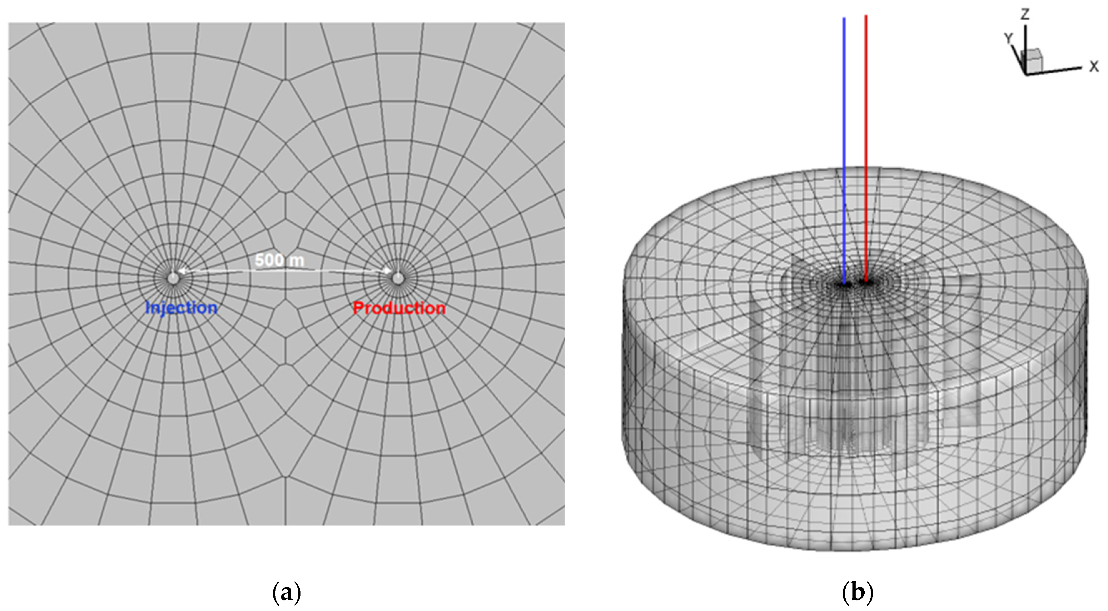
Based on the geological and thermo-physical conditions of the Cambrian–Ordovician limestone geothermal reservoir in the Heze uplift, a three-dimensional model was constructed in this study, as depicted in Figure 2. The reservoir has a depth of 2500 m and a thickness of 50 m. A doublet well system with a well spacing of 500 m is established at the center of the model. The model exhibits an almost circular shape, with its boundary located at a distance of 5 km from the doublet well system to minimize any influence on flow characteristics. Consequently, a constant boundary condition was applied. Furthermore, the heat exchange between the reservoir and cap/base rock was considered using a semi-analytical solution proposed by Vinsome and Westerveld [21]. Additional geometric and hydrogeological information can be found in Table 1.

2.2. Parameters Configuration

Typically, the reservoir is initially saturated with resident water. The displacement process of resident water by CO2 takes considerable time to establish a CO2-dominant reservoir. In Xu et al.’s study [17], the fixed pressure is set for both injection and production, with the production pressure specified based on the phase state of the fluid, whether it is predominantly water or CO2. In this study, a constant mass flow rate condition of 50 kg/s was adopted as the base case for both injection and production, with an injection temperature of 33 °C.
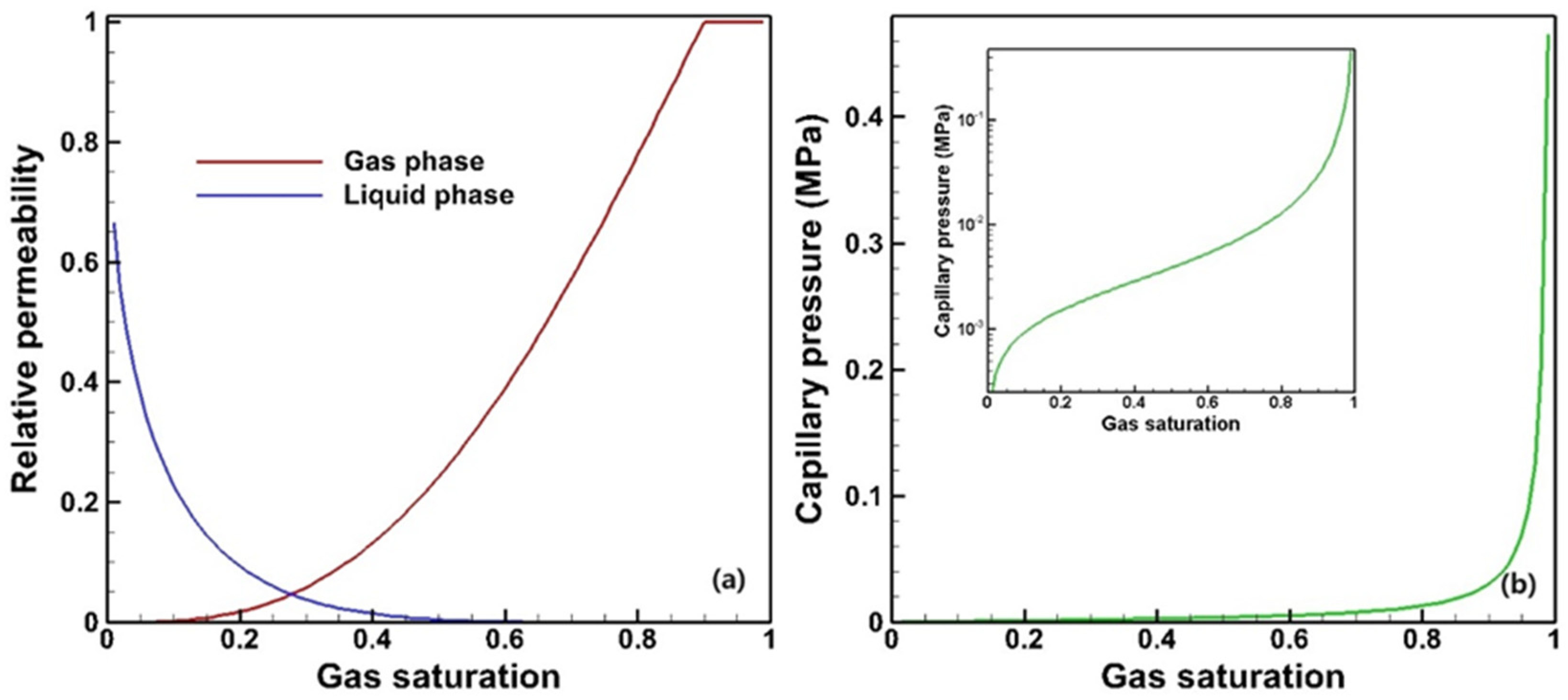
The flow equations used to describe the multiphase flow in the reservoir employs Darcy’s law. The fundamental parameters significantly influencing the multiphase flow are the relative permeability and capillary pressure. The relative permeability is a dimensionless parameter that describes the ability of a fluid phase to flow in the presence of other immiscible phases. It quantifies the fraction of the total permeability available to a specific fluid phase at a given saturation. Capillary pressure is the pressure difference across the interface between two immiscible fluids in a porous medium. It arises due to the capillary forces at the fluid–fluid interface and plays a crucial role in determining the direction and rate of fluid movement. The model adopted in this study is van Genuchten’s model [22], and the parameters are listed in Table 2.
According to these parameters, the relative permeability and capillary pressure profiles are illustrated in Figure 3.
The initial mineralogical compositions of the reservoir are presented in Table 3. The carbonate rocks predominantly consist of calcite, dolomite, and a small amount of quartz. The equilibrium constants (K) for the aqueous species and minerals were derived from the EQ3/6 V7.2b database [23], which was generated using the thermodynamic data of SUPCRT92 [24]. Equation (1) depicts the calculation of these equilibrium constants as a unary function dependent on the absolute temperature (T). For the specific fitting parameters associated with each mineral, please refer to Table 3. The initial water chemistry is in thermodynamic equilibrium with the minerals at a reservoir temperature of 100 °C. The concentrations of certain primary species are outlined in Table 4.
log 10 K = a × ln T + b + c × T + d / T + e / T 2
The concentrations of certain primary species are presented in Table 4, and some minor amount species are excluded. The pH is predicted to be 6.92, indicating weak alkalinity at a temperature of 100 °C. Among the carbonate species, HCO3 exhibits dominance.

2.3. Simulation Approach

The non-isothermal reactive transport code TOUGHREACT [25,26] was utilized in the present simulations; this incorporates reactive chemistry into the multiphase fluid and heat flow code TOUGH2 [27]. The ECO2N fluid property module developed by Spycher and Pruess [28] was employed to provide an accurate depiction of the thermophysical properties for mixtures of water and CO2 under the conditions encountered in this carbonate CO2–water system of interest (T < 100 °C, P < 60 MPa).
Based on the framework of TOUGHREACT, the wellbore flow function is also added; this refers do T2Well, developed by Pan and Oldenburg [29,30]. It treats the wellbore and reservoir as an integrated system by utilizing different sets of governing equations to describe the multiphase flow in each domain. In the wellbore, a one-dimensional momentum equation is used to describe the flow, while multiphase Darcy’s Law is employed in the reservoir. The drift–flux model (DFM) [31] is introduced to describe the two-phase flow characteristics. Regarding the energy balance equations, both kinetic energy and gravitational potential energy are considered in the wellbore’s energy balance equation, which is neglected within the reservoir.
The model has been designed to effectively handle an extensive array of chemical species across various phases, including liquid, gas, and solid. This framework seamlessly incorporates the dynamic interplay between fluid flow and chemistry, ensuring a comprehensive understanding of the system’s behavior. Notably, the model takes into consideration the temporal variations in porosity and permeability influenced by mineral dissolution and precipitation, and the feedback of the alterations on fluid flow pathways. A simple cubic Kozeny–Carman grain model has been adopted for this study to establish the relationship between porosity and permeability. Furthermore, the model encompasses an extensive range of subsurface thermal-physical-chemical processes, carefully examining their interactions under diverse thermo-hydrological and geochemical conditions. Factors such as pressure, temperature, water saturation, ionic strength, pH, and Eh are meticulously considered to accurately capture the system’s intricacies. For more comprehensive insights into the model’s process capabilities, detailed information can be found in the work of Xu and Pruess [25].
The numerical method employed for simulating fluid flow and chemical transport in this study is the integral finite difference (IFD) method for spatial discretization. The IFD method offers a flexible approach to discretizing geologic media, allowing for the use of irregular grids. This flexibility is particularly advantageous when simulating flow, transport, and fluid–rock interactions in heterogeneous and fractured rock systems with varying petrology. To solve the flow, transport, and kinetic geochemical equations, an implicit time-weighting scheme is utilized. This scheme ensures accurate and stable solutions.
Additionally, a sequential iterative approach is adopted to couple transport with geochemical reactions, enabling the simulation of complex interactions between the fluid flow and chemical processes. The model presented in this paper can be applied to porous and fractured media of various dimensions. Overall, the IFD method, combined with the implicit time-weighting scheme and sequential iterative approach, provides a robust framework for simulating fluid flow, chemical transport, and geochemical reactions in diverse geological settings.

3. Results and Discussion

3.1. Fluid and Heat Flow

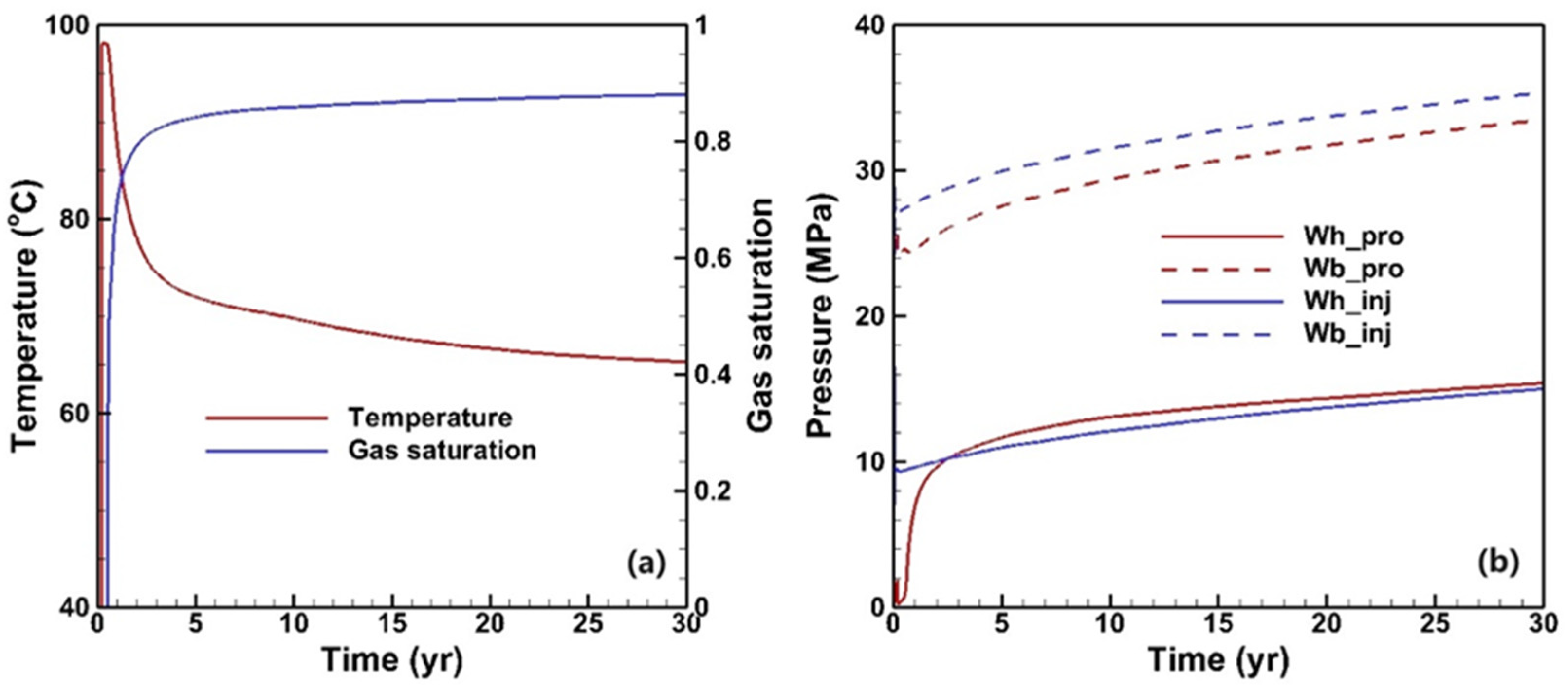
Based on Figure 4a, the displacing process can be divided into two distinct stages. Initially, within the first 0.5 years, the production fluid primarily consists of a single-phase fluid, i.e., liquid water. Subsequently, there is a rapid CO2 breakthrough, resulting in a substantial increase in gas saturation up to 0.8 after 2 years, which remains stable throughout the remaining duration of the operation. The production fluid remains in a two-phase state until the end, indicating that a phase separation process is needed for subsequent heat exchange. In Xu et al.’s study [17], a well pattern of “five-spot” is adopted, and a limited reservoir volume results in a high CO2 saturation within the reservoir; this then makes the gas saturation of the production fluid approach 1 after 5 years of operation. However, in this study, implementing a doublet well pattern ensures that there is a constant influx of water into the production wellbore, thereby preventing it from reaching pure CO2 single-phase conditions. Notably, when the production fluid exists in its aqueous phase, the temperature closely approximates 100 °C. However, as the CO2 content progressively rises, the temperature experiences a rapid decline owing to the Joule–Thomson effect. Eventually, the temperature stabilizes above 65 °C.
The pressure evolution at the wellhead and bottom of the injection and production wells is depicted in Figure 4b. Except for the production wellhead, a gradual increase the in pressure profiles is observed during operation. This can be attributed to the larger volume occupied by low-density CO2 compared to water under equivalent injection and production rates. As CO2 breakthrough occurs, high-density water within the production wellbore is replaced by low-density CO2, leading to a rapid rise in the wellhead pressure. After three years, this pressure exceeds that of injection, indicating a thermosiphon phenomenon resulting from differences in the fluid density within the wellbores.
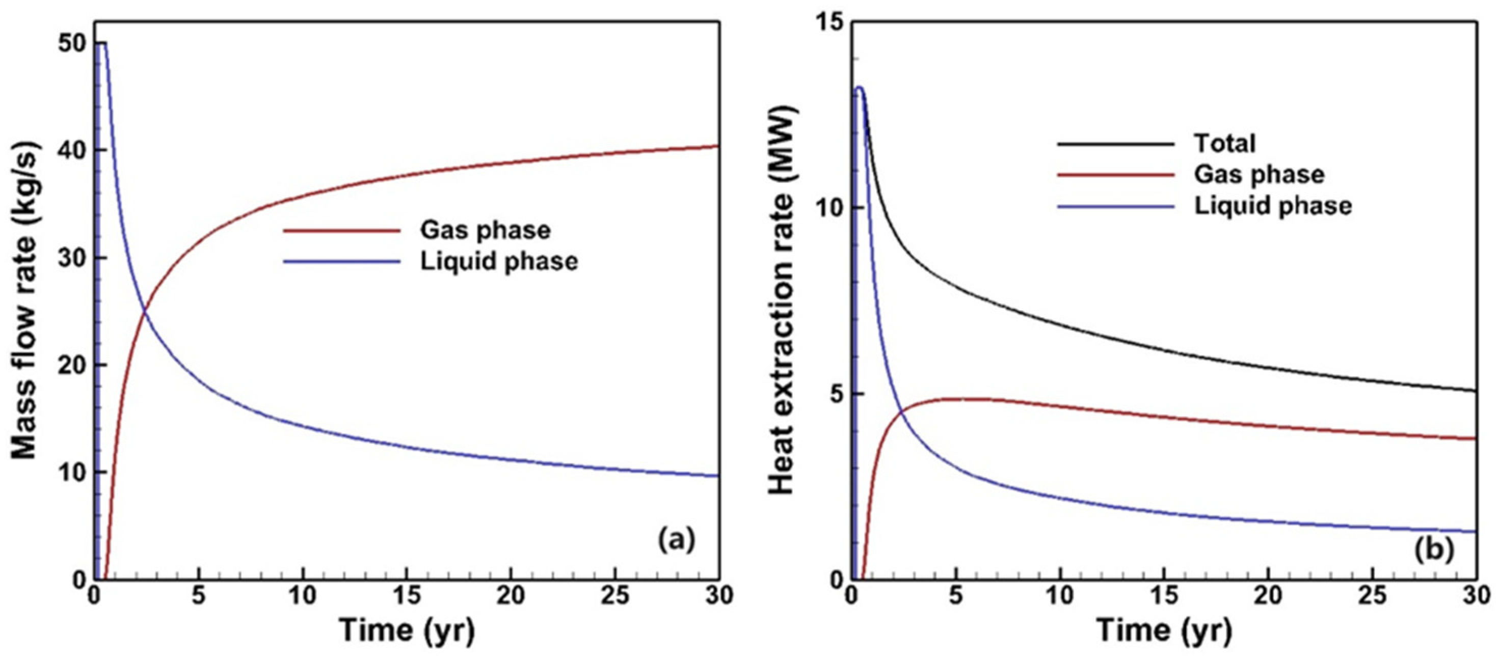
The mass flow and heat extraction rates are depicted in Figure 5, where the trend of the mass flow rate for different phases aligns with the phase saturation evolution (Figure 5a). Despite CO2 having a relatively low density, when the gas saturation of the production fluid approaches 0.9, the gas phase contributes approximately 0.8 to the total mass flow rate, which is equivalent to 40 kg/s. Figure 5b illustrates the heat extraction rate for different phases. Since specific enthalpy values depend on the reference state decisions for each component, separate calculations are performed to determine the total heat extraction rate based on individual phases, as in Equation (2), where H and F represent the specific enthalpy and mass flow rate of the fluid, respectively.
E = H p r o ,   C O 2 H i n j ,   C O 2 F p r o ,   C O 2 + H p r o ,   H 2 O H i n j ,   H 2 O F p r o ,   H 2 O
Initially, when only single-phase water is present in the production fluid, a maximum heat extraction rate exceeding 13 MW is achieved. However, as CO2 breakthrough occurs, there is a subsequent decrease in the heat extraction rate due to its low specific heat capacity, which eventually stabilizes at around 5 MW by the end of operation.
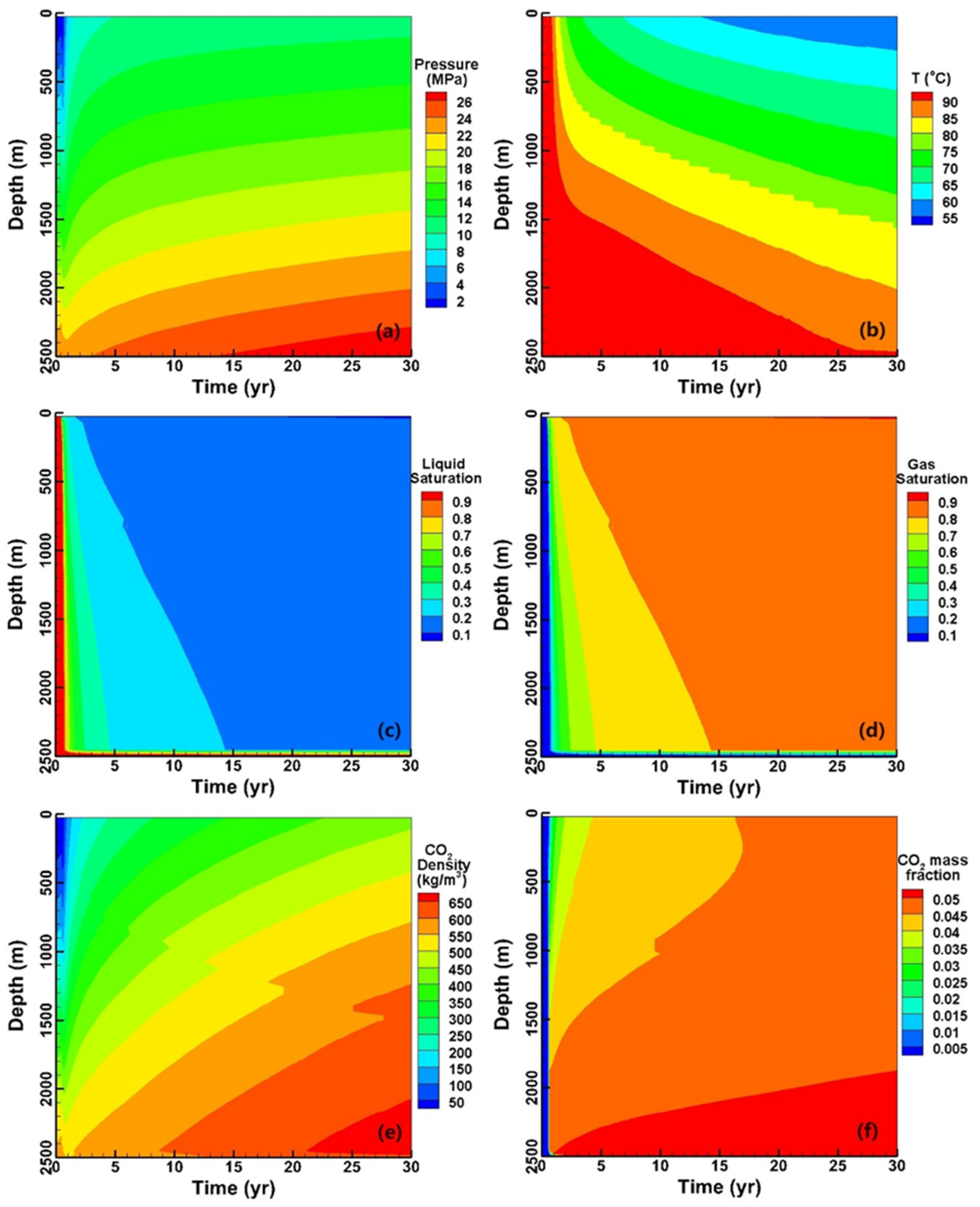
The variables’ evolution along the entire production wellbore is depicted in Figure 6, facilitating a comprehensive understanding of the evolutionary characteristics within the wellbore. The variables, including pressure, temperature, and phase saturation, from the wellhead to the bottom exhibit a predominantly monotonic trend. However, the density of CO2 and dissolution are intricate functions of pressure and temperature, resulting in minor fluctuations in both the density and mass fraction along the wellbore. It is worth noting that, due to the buoyancy, CO2 tends to migrate along the upper portion of the reservoir, making the gas saturation at the reservoir bottom lower than 0.1 throughout the entire operation.
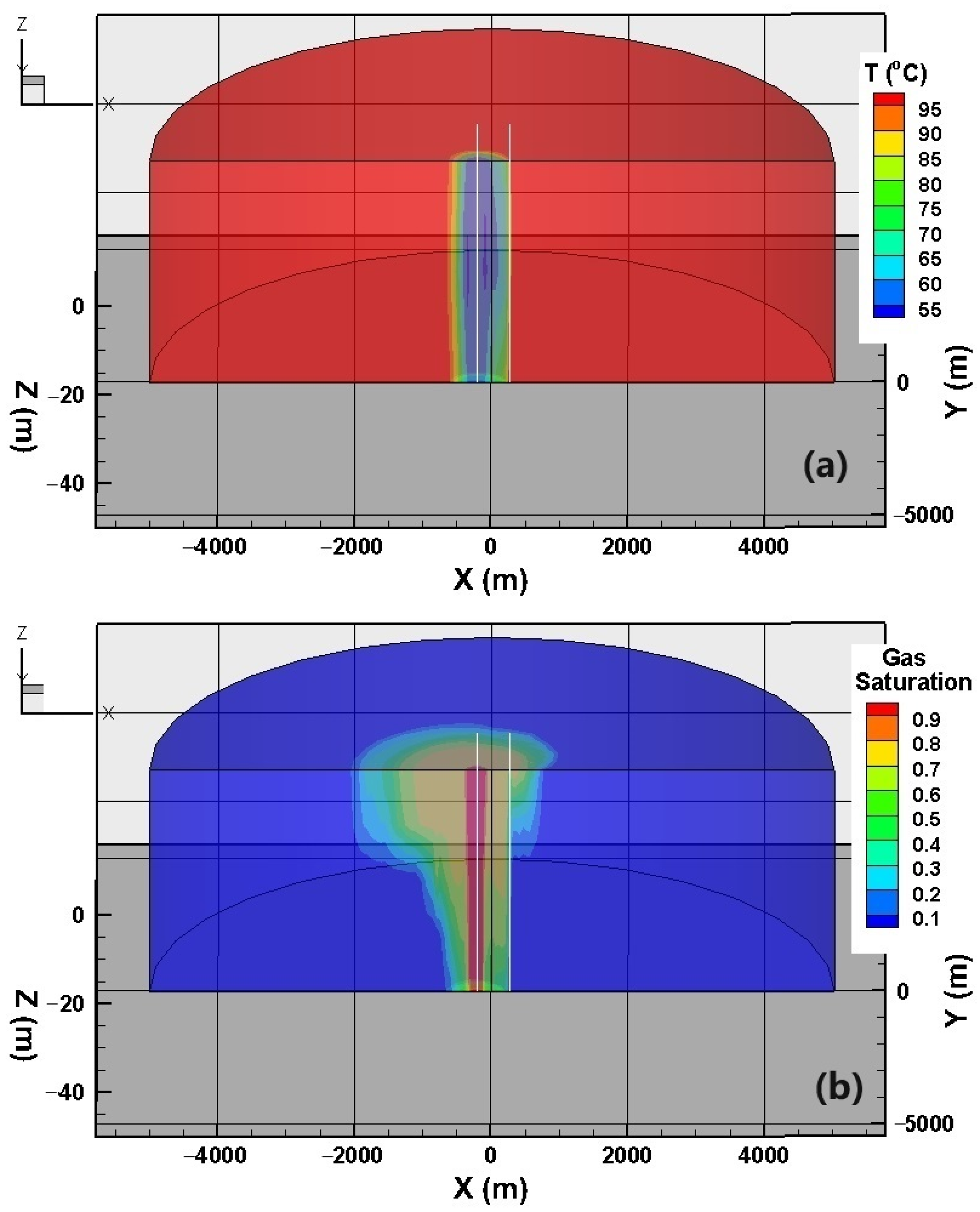
We then delve into the temporal evolution of the variables within the reservoir, as illustrated in Figure 7. To facilitate our analysis, we have partitioned the modeled domain into two halves along the slice connecting the two wells. Notably, the gas saturation distribution exhibits a conical shape, which can be attributed to the upward flow tendency of CO2, as previously discussed. Consequently, it becomes apparent that the migration of CO2 to the opposite side of the production well primarily occurs along the upper region of the reservoir. A CO2 single-phase zone emerges at a distance of tens of meters from the injection well.
Compared to the phase saturation, the temperature contours exhibit a cylindrical shape due to the sufficient heating of CO2 by both the primary formation and confining layers. The lowest temperature at the bottom of the injection well is approximately 50 °C, which is nearly 20 °C higher than the injection temperature. In addition to the Joule–Thomson effect, gravitational potential energy also plays a certain role.

3.2. Reactive Transport Process

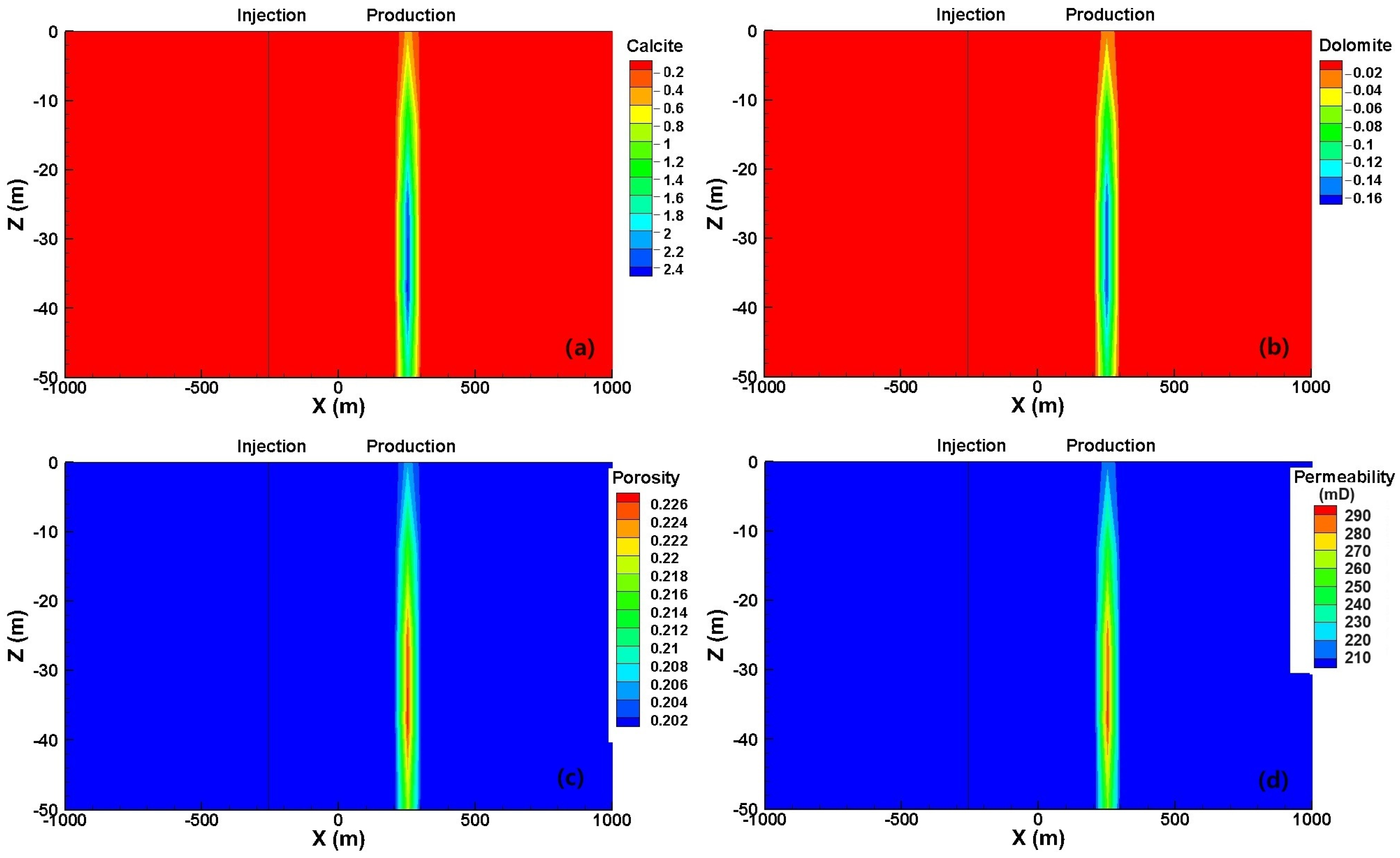
The mineral dissolution/precipitation pattern and the associated variations in porosity/permeability during the reactive transport process are depicted in Figure 8. Notably, a predominant geochemical reaction is observed solely in the vicinity of the production well, while minimal alteration takes place even along the flow path from the injection to the production well. Specifically, approximately 2.4% of the total volume is attributed to calcite dissolution, accompanied by a dissolution of 1.6% dolomite, which increases the porosity to 0.226, and a significant 50% enhancement of permeability, resulting in a permeability value of 300 mD. Therefore, it can be inferred that scaling is unlikely to occur in the carbonate reservoir, ensuring sustained efficiency over a long-term operation.
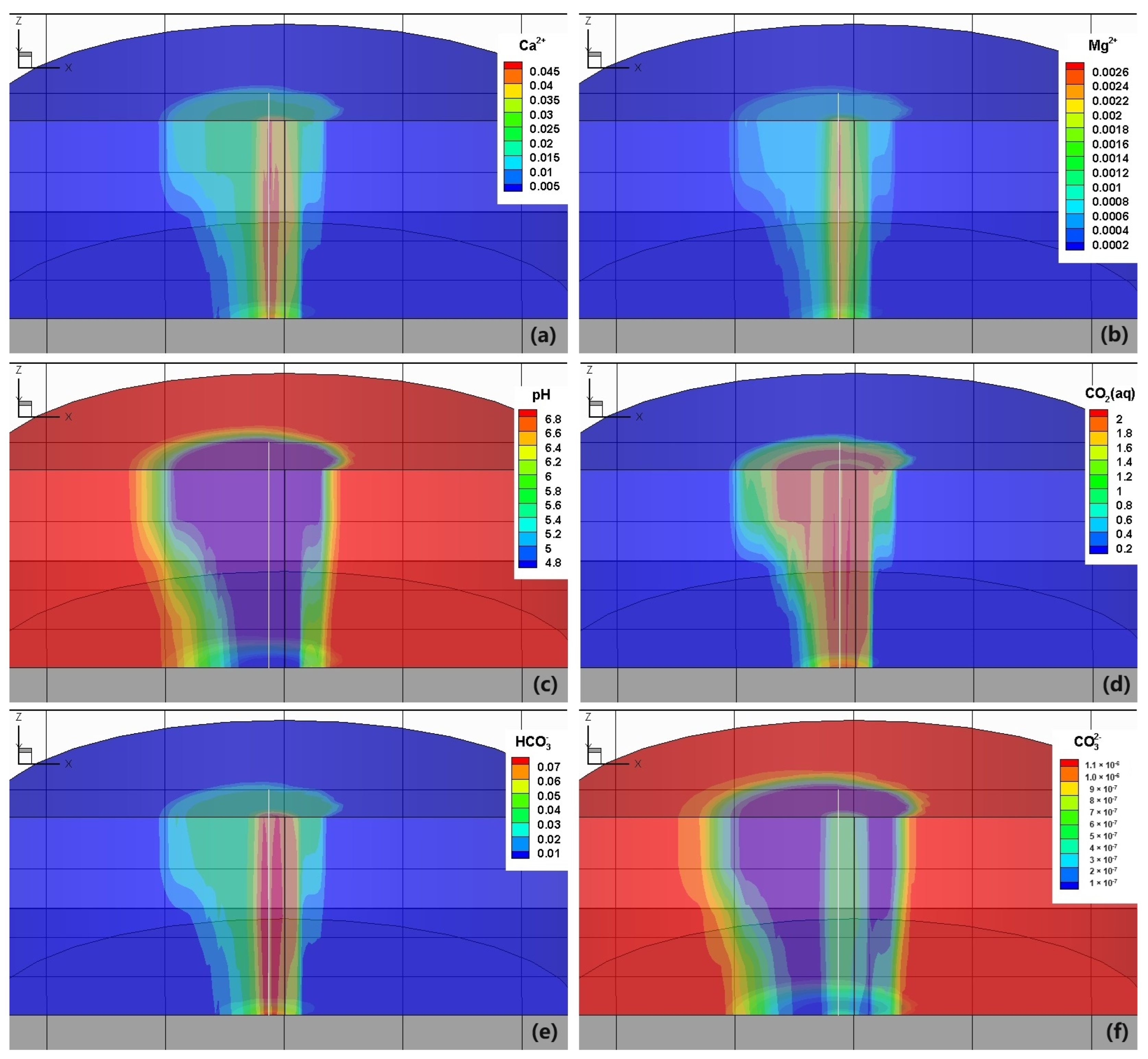
The concentration of species and the pH are depicted in Figure 9 so as to enhance the comprehension of the reactive transport process. The contours resemble gas saturation patterns. The dissolution of CO2 results in a decrease in pH, triggering the dissolution of carbonate rocks and subsequently releasing significant amounts of Ca2+ and Mg2+ [15]. Furthermore, the dissolution of H2O into the CO2 gas phase further concentrates it, causing its concentrations to exceed their initial values by more than tenfold. The low saturation level of the aqueous phase hinders its mobility, facilitating the rapid attainment of mineral dissolution equilibrium. Meanwhile, for the production well, the CO2 from the injection well and the substantial volume of low-concentration water from the other side of the production well get mixed at the well bottom, leading to a continuous dissolution of calcite and dolomite. The carbon element exists in three different species. CO2(aq) takes the dominant role in such a low pH condition. The concentration of HCO3 also increases compared to its initial value, but the concentration of CO32− decreases.
Reactive transport modeling has been conducted for a five-spot well configuration of a potential CO2-geothermal system, considering the thermal conditions and mineralogical composition of the carbonate reservoir at the Songliao basin and Cranfield sites. The precipitation of carbonate minerals and clay does not significantly impact porosity or flow circulation. During the initial 10-year period, some amount of CO2 is trapped by carbonate mineral precipitation. The limited available information on mineral alteration, porosity reduction, and carbon fixation in natural CO2 reservoirs generally aligns with our simulation results. Therefore, both sustained geothermal energy recovery and geological storage of CO2 can be achieved. The extent of porosity decrease and amount of trapped CO2 depend on the primary mineral composition. Future studies should conduct sensitivity analyses on different rock mineralogies. Utilizing natural analogs of high-pressure CO2 reservoirs could provide valuable insights for refining thermodynamic, kinetic, and physical data. The reactivity between supercritical CO2 and rock remains poorly understood; thus experimental investigations are necessary to quantitatively describe reaction kinetics.
The concentrations of certain primary species are depicted in Figure 10, including Ca2+ (Figure 10a), HCO3- (Figure 10b), CO2(aq) (Figure 10c), and pH (Figure 10d). Upon CO2 breakthrough, the concentrations of Ca2+, Mg2+, and HCO3 instantaneously increase to approximately ten times their initial values, followed by a gradual decrease with minimal fluctuations. Simultaneously, the concentration of dissolved CO2 rises while the pH consistently declines.
The total amount of CO2 injected into the reservoir is 47.304 million tons (Mtons), among which 33.0255 Mtons of CO2 has been extracted from the production fluid, including the gaseous and dissolved phases. However, a notable portion of the injected CO2, approximately 13.85 Mtons, remains trapped within the reservoir in the two phases. This difference in mass is the CO2 trapped in the mineral phase, which is about 0.4285 Mtons. It transformed into stable compounds within the geological formations, accounting for 3% of the total CO2 storage amount.

4. Conclusions

In this study, we have developed a comprehensive wellbore–reservoir coupling reactive transport model based on specific information obtained from the Ordovician limestone geothermal reservoir in Shandong, China. This study has provided valuable insights into the potential of utilizing CO2 as a geothermal fluid in carbonate reservoirs. Some conclusions can be drawn.
Firstly, it exhibits a relatively satisfactory heat extraction behavior with a heat extraction rate that can reach 13 MW and remain above 5 MW. The production fluid maintains a two-phase state after the breakthrough of CO2, indicating the need for a phase separation process for further heat exploitation. The decline in the production fluid temperature is primarily attributed to the Joule–Thomson effect. Due to buoyancy, CO2 tends to migrate along the top of the reservoir, resulting in a gas saturation at the bottom of the well that is lower than 0.06.
Furthermore, this study highlights the importance of understanding the complex geochemical interactions between CO2 and carbonate minerals. When considering the carbonate rocks without feldspar and clay minerals, the CO2-induced dissolution of minerals concentrates in the vicinity of the production well, and scaling is unlikely to occur in the carbonate reservoir, ensuring sustained efficiency over a long-term operation.
Overall, the research on the CO2 geothermal system in carbonate rocks underscores its potential as a sustainable and environmentally friendly energy solution. This dual benefit makes the CO2 geothermal system in carbonate rocks a promising avenue for achieving sustainable energy production while addressing climate change concerns. However, further investigations are required to address technical challenges such as reservoir heterogeneity, scaling issues, and economic viability. By advancing our knowledge in these areas, we can unlock the full potential of the CO2 geothermal system in carbonate rocks and contribute to a greener and more sustainable future.

Author Contributions

Conceptualization, X.L. and X.T.; methodology, G.F.; software, G.F.; validation, F.Z. and S.S.; formal analysis, X.L.; investigation, S.S.; resources, X.T.; data curation, F.Z.; writing—original draft preparation, X.L.; writing—review and editing, X.T. and G.F.; visualization, X.L.; supervision, X.T.; project administration, X.T.; funding acquisition, X.T. All authors have read and agreed to the published version of the manuscript.

Funding

This research was jointly funded by Key R&D program of Shandong Province, China (grant number 2023CXGC010904); Science and Technology Innovation Project of Shandong Provincial Bureau of Geology & Mineral Resources (grant number HJ202112); Shandong Lunan Geological Engineering Exploration Institute Open Fund (grant number DKJS202203); National Natural Science Foundation of China (grant number 42372284).

Data Availability Statement

Dataset available on request from the authors.

Conflicts of Interest

The authors declare no conflicts of interest.

References

  1. Brown, D. A Hot Dry Rock Geothermal Energy Concept Utilizing Supercritical CO2 Instead of Water. In Proceedings of the Twenty-Fifth Workshop on Geothermal Reservoir Engineering, Stanford University, Stanford, CA, USA, 24–26 January 2000. [Google Scholar]
  2. Pruess, K. Enhanced geothermal systems (EGS) using CO2 as working fluid—A novel approach for generating renewable energy with simultaneous sequestration of carbon. Geothermics 2006, 35, 351–367. [Google Scholar] [CrossRef]
  3. Pruess, K. On production behavior of enhanced geothermal systems with CO2 as working fluid. Energy Convers. Manag. 2008, 49, 1446–1454. [Google Scholar] [CrossRef]
  4. Luo, F.; Xu, R.-N.; Jiang, P.-X. Numerical investigation of fluid flow and heat transfer in a doublet enhanced geothermal system with CO2 as the working fluid (CO2–EGS). Energy 2014, 64, 307–322. [Google Scholar] [CrossRef]
  5. Cui, G.; Zhang, L.; Ren, B.; Enechukwu, C.; Liu, Y.; Ren, S. Geothermal exploitation from depleted high temperature gas reservoirs via recycling supercritical CO2: Heat mining rate and salt precipitation effects. Appl. Energy 2016, 183, 837–852. [Google Scholar] [CrossRef]
  6. Cui, G.; Ren, S.; Rui, Z.; Ezekiel, J.; Zhang, L.; Wang, H. The influence of complicated fluid-rock interactions on the geothermal exploitation in the CO2 plume geothermal system. Appl. Energy 2018, 227, 49–63. [Google Scholar] [CrossRef]
  7. Adams, B.M.; Kuehn, T.H.; Bielicki, J.M.; Randolph, J.B.; Saar, M.O. On the importance of the thermosiphon effect in CPG (CO2 plume geothermal) power systems. Energy 2014, 69, 409–418. [Google Scholar] [CrossRef]
  8. Atrens, A.D.; Gurgenci, H.; Rudolph, V. CO2 thermosiphon for competitive geothermal power generation. Energy Fuels 2009, 23, 553–557. [Google Scholar] [CrossRef]
  9. Atrens, A.D.; Gurgenci, H.; Rudolph, V. Electricity generation using a carbon-dioxide thermosiphon. Geothermics 2010, 39, 161–169. [Google Scholar] [CrossRef]
  10. Atrens, A.D.; Gurgenci, H.; Rudolph, V. Economic Optimization of a CO2-Based EGS Power Plant. Energy Fuels 2011, 25, 3765–3775. [Google Scholar] [CrossRef]
  11. Majer, E.L.; Baria, R.; Stark, M.; Oates, S.; Bommer, J.; Smith, B.; Asanuma, H. Induced seismicity associated with Enhanced Geothermal Systems. Geothermics 2007, 36, 185–222. [Google Scholar] [CrossRef]
  12. Zang, A.; Oye, V.; Jousset, P.; Deichmann, N.; Gritto, R.; McGarr, A.; Majer, E.; Bruhn, D. Analysis of induced seismicity in geothermal reservoirs—An overview. Geothermics 2014, 52, 6–21. [Google Scholar] [CrossRef]
  13. Randolph, J.B.; Saar, M.O.; Bielicki, J. Geothermal Energy Production at Geologic CO2 Sequestration sites: Impact of Thermal Drawdown on Reservoir Pressure. Energy Procedia 2013, 37, 6625–6635. [Google Scholar] [CrossRef]
  14. Schifflechner, C.; Wieland, C.; Spliethoff, H. CO2 Plume Geothermal (CPG) Systems for Combined Heat and Power Production: An Evaluation of Various Plant Configurations. J. Therm. Sci. 2022, 31, 1266–1278. [Google Scholar] [CrossRef]
  15. Cui, G.; Zhang, L.; Tan, C.; Ren, S.; Zhuang, Y.; Enechukwu, C. Injection of supercritical CO2 for geothermal exploitation from sandstone and carbonate reservoirs: CO2–water–rock interactions and their effects. J. CO2 Util. 2017, 20, 113–128. [Google Scholar] [CrossRef]
  16. Thomas, J.; Frost, R.R.; Harvey, R.D. Thermal conductivity of carbonate rocks. Eng. Geol. 1973, 7, 3–12. [Google Scholar] [CrossRef]
  17. Xu, T.; Feng, G.; Hou, Z.; Tian, H.; Shi, Y.; Lei, H. Wellbore–reservoir coupled simulation to study thermal and fluid processes in a CO2-based geothermal system: Identifying favorable and unfavorable conditions in comparison with water. Environ. Earth Sci. 2015, 73, 6797–6813. [Google Scholar] [CrossRef]
  18. André, L.; Audigane, P.; Azaroual, M.; Menjoz, A. Numerical modeling of fluid–rock chemical interactions at the supercritical CO2–liquid interface during CO2 injection into a carbonate reservoir, the Dogger aquifer (Paris Basin, France). Energy Convers. Manag. 2007, 48, 1782–1797. [Google Scholar] [CrossRef]
  19. Ueda, A.; Kato, K.; Ohsumi, T.; Yajima, T.; Ito, H.; Kaieda, H.; Metcalfe, R.; Takase, H. Experimental studies of CO2-rock interaction at elevated temperatures under hydrothermal conditions. Geochem. J. 2005, 39, 417–425. [Google Scholar] [CrossRef]
  20. Xu, T.; Feng, G.; Shi, Y. On fluid–rock chemical interaction in CO2-based geothermal systems. J. Geochem. Explor. 2014, 144, 179–193. [Google Scholar] [CrossRef]
  21. Vinsome, P.; Westerveld, J. A simple method for predicting cap and base rock heat losses in thermal reservoir simulators. J. Can. Pet. Technol. 1980, 19, 87–90. [Google Scholar] [CrossRef]
  22. Van Genuchten, M.T. A closed-form equation for predicting the hydraulic conductivity of unsaturated soils 1. Soil Sci. Soc. Am. J. 1980, 44, 892–898. [Google Scholar] [CrossRef]
  23. Wolery, T. EQ3/6, a Software Package for Geochemical Modeling of Aqueous Systems: Package Overview and Installation Guide, Version 7.0; Lawrence Livermore National Laboratory: Livermore, CA, USA, 1992.
  24. Johnson, J.W.; Oelkers, E.H.; Helgeson, H.C. SUPCRT92: A software package for calculating the standard molal thermodynamic properties of minerals, gases, aqueous species, and reactions from 1 to 5000 bar and 0 to 1000 °C. Comput. Geosci. 1992, 18, 899–947. [Google Scholar] [CrossRef]
  25. Xu, T.; Spycher, N.; Sonnenthal, E.; Zhang, G.; Zheng, L.; Pruess, K. TOUGHREACT Version 2.0: A simulator for subsurface reactive transport under non-isothermal multiphase flow conditions. Comput. Geosci. 2011, 37, 763–774. [Google Scholar] [CrossRef]
  26. Xu, T.; Sonnenthal, E.; Spycher, N.; Pruess, K. TOUGHREACT—A simulation program for non-isothermal multiphase reactive geochemical transport in variably saturated geologic media: Applications to geothermal injectivity and CO2 geological sequestration. Comput. Geosci. 2006, 32, 145–165. [Google Scholar] [CrossRef]
  27. Pruess, K.; Oldenburg, C.; Moridis, G. TOUGH2 User’s Guide, Version 2.0; Lawrence Berkeley National Laboratory: Berkeley, CA, USA, 1999.
  28. Pruess, K. ECO2N: A TOUGH2 Fluid Property Module for Mixtures of Water, NaCl and CO2; Lawrence Berkeley National Laboratory: Berkeley, CA, USA, 2005. [Google Scholar]
  29. Pan, L.; Oldenburg, C.M.; Wu, Y.-S.; Pruess, K. T2Well/ECO2N Version 1.0: Multiphase and Non-Isonthermal Model for Coupled Wellbore-Reservoir Flow of Carbon Dioxide and Variable Salinity Water; Lawrence Berkeley National Laboratory: Berkeley, CA, USA, 2011. [Google Scholar]
  30. Pan, L.; Oldenburg, C.M. T2Well—An integrated wellbore–reservoir simulator. Comput. Geosci. 2014, 65, 46–55. [Google Scholar] [CrossRef]
  31. Shi, H.; Holmes, J.A.; Durlofsky, L.J.; Aziz, K.; Diaz Teran Ortegon, L.R.; Alkaya, B.; Oddie, G. Drift-flux modeling of two-phase flow in wellbores. SPE J. 2005, 10, 24–33. [Google Scholar] [CrossRef]
Figure 1. The Cambrian–Ordovician limestone geothermal reservoir is predominantly found in concealed and buried forms within the central and lateral regions of the study area. The distribution pattern of this geothermal reservoir is strictly governed by regional major faults, with Cenozoic, Mesozoic, and Paleozoic formations acting as impermeable cap layers. The depth of the Cambrian–Ordovician geothermal reservoir gradually increases from east to west, thereby influencing its temperature regime. As the depth deepens, a corresponding rise in temperature occurs. This particular type of geothermal system primarily operates through conduction.
Energies 17 02910 g001
Figure 2. Overview of the doublet well pattern with a computational grid for thte modeling domain (a) and 3D sketch of the modeling grid (b).
Energies 17 02910 g002
Figure 3. Relative permeability (a) and capillary pressure (b) profiles according to van Genuchten’s model.
Energies 17 02910 g003
Figure 4. The temporal evolution of the production fluid temperature, gas saturation (a), and pressures of the two wells (b).
Energies 17 02910 g004
Figure 5. Evolution of the mass flow rate (a) and heat extraction rate (b) of different phases.
Energies 17 02910 g005
Figure 6. The variables monitored within the production well, including (a) pressure, (b) temperature, (c) liquid-phase saturation, (d) gas-phase saturation, (e) CO2 density, and (f) CO2 mass fraction.
Energies 17 02910 g006
Figure 7. The variables monitored within the reservoir, including (a) temperature and (b) gas saturation.
Energies 17 02910 g007
Figure 8. Changes in volume fraction percentage of (a) calcite, (b) dolomite, and the distribution of (c) porosity and (d) permeability after 30 years of operation.
Energies 17 02910 g008
Figure 9. Concentration distribution of some primary species and pH in the reservoir after 30 years of operation. (a) Ca2+, (b) Mg2+, (c) pH, (d) CO2, (e) HCO3 and (f) CO32−.
Energies 17 02910 g009
Figure 10. Species concentration and pH of the production fluid. (a) Ca2+, (b) HCO3 (c) CO2 and (d) pH.
Energies 17 02910 g010
Table 1. Geometric and hydrogeological specifications for the simulation.
Formation
Depth2500 m
Thickness50 m
Porosity0.2
Permeability2.0 × 10−13 m2
Rock grain density2650 kg/m3
Rock specific heat920 J/kg/°C
Rock thermal conductivity2.51 W/m/°C
Well spacing500 m
Reservoir temperature100 °C
Reservoir pressure24.6 MPa
Wellbores
Diameter0.18 m
Roughness0.046 mm
Heat conductivity2.51 W/m/°C
The inclination of wellsVertical
Production/Injection
Injection temperature 33 °C
Mass flow rate50 kg/s
Table 2. Parameters for relative permeability and capillary pressure model.
Parameter for Relative Permeability
(van Genuchten’s Model for Liquid and Corey’s Model for Gas)
Residual liquid saturation0.10
Residual gas saturation0.01
Saturated liquid saturation1.00
λ0.457
Parameter for capillary pressure (van Genuchten’s model)
Residual liquid saturation0.00
Saturated liquid saturation1.00
λ0.457
Gas entry pressure2000 Pa
Maximum capillary pressure1.0 MPa
Table 3. List of minerals considered and parameters for calculating the kinetic rate constants and equilibrium constants of minerals. Note that (1) all rate constants are listed for dissolution; (2) A is the specific surface area, k25 is the kinetic constant at 25 °C, Ea is the activation energy, and n is the power term [25].
MineralCalciteDolomiteQuartz
Initial volume of solid (%)85105
A (cm2/g)9.89.89.8
Parameters for kinetic rate lawNeutral mechanismk25 (mol/m2/s)1.55 × 10−62.95 × 10−81.02 × 10⁻¹⁴
Ea (kJ/mol)23.552.287.7
Acid mechanismk25 (mol/m2/s)0.5016.46 × 10−4-
Ea (kJ/mol)14.436.1-
n (H+)1.01.0-
Parameters for equilibrium constantsa142.62643298.77008−23.56122
b−904.766951899.4949154.45001
c−0.14454508−0.299744010.017816442
d50,724.016106,828.32−10,900.331
e2,936,998.1−6,150,330.1648,509.8
Table 4. The concentration of primary species in the carbonate reservoir.
Chemical SpeciesConcentration (mol/L)
H+1.279 × 10⁻⁷
OH4.854 × 10−6
Ca2+6.788 × 10⁻⁴
Mg2+2.389 × 10⁻⁵
HCO31.406 × 10−3
CO32−1.140 × 10⁻⁶
CO2(aq)3.929 × 10⁻⁴
Ca(HCO3)+1.988 × 10⁻⁵
Mg(HCO3)+7.263 × 10⁻⁷
pH6.92
Disclaimer/Publisher’s Note: The statements, opinions and data contained in all publications are solely those of the individual author(s) and contributor(s) and not of MDPI and/or the editor(s). MDPI and/or the editor(s) disclaim responsibility for any injury to people or property resulting from any ideas, methods, instructions or products referred to in the content.