Review

Biogas Upgrading Technology: Conventional Processes and Emerging Solutions Analysis

by
Matteo Galloni
and
Gioele Di Marcoberardino
*
Dipartimento di Ingegneria Meccanica ed Industriale, Università degli Studi di Brescia, Via Branze 38, 25123 Brescia, Italy
*
Author to whom correspondence should be addressed.
Energies 2024, 17(12), 2907; https://doi.org/10.3390/en17122907
Submission received: 14 May 2024 / Revised: 1 June 2024 / Accepted: 9 June 2024 / Published: 13 June 2024
(This article belongs to the Special Issue New Trends in Biofuels and Bioenergy for Sustainable Development II)

Abstract

:
The purpose of this research is to investigate a variety of approaches to the conversion of biomass, with a particular emphasis on employing anaerobic digestion and biogas upgrading systems. An analysis of the existing technologies is performed, with a focus on highlighting the benefits and downsides of each alternative. In order to assess the effects of nitrogen and oxygen in the biogas on the cryogenic distillation process, an investigation is being carried out. The findings suggest that the presence of these two chemical species in the biogas necessitates the final condensation of methane in order to separate them from one another. In conclusion, a qualitative economic analysis is carried out in order to ascertain the most cost-effective strategy that can be implemented in a typical Italian installation. According to the assumptions that were used, membrane separation is the solution that offers the most cost-effectiveness.

1. Introduction

It is crucial to shift the energy sector towards sources with a lower carbon footprint to reduce the harmful impacts on the global environment caused by human activities. Renewable energy needs to make up about 40% of total energy generation in all sectors by 2030 [1] to align with the EU’s carbon-neutral objective [2]. Biomass, derived from organic materials as plant residues, animal waste, and the organic fraction of municipal solid waste (OFMSW), offers a promising opportunity for producing green energy. Moreover, using biomass in this manner allows for the conversion of waste into a valuable resource, aligning with the circular economy principles [3]. The key advantages of biomass compared to other renewable sources are its independence from weather conditions and its ability to more easily meet electricity demand through physical accumulation [4].
There are multiple methods for converting biomass into biofuel; these methods are illustrated in Figure 1, divided by the kind of process involved in the conversion. This work [5] presents different technologies focusing on the product’s characteristics, together with a quick overview of the primary advantages and drawbacks. Physical biomass conversion involves modifying biomass by preprocessing activities, size reduction, drying, and densification. This method converts biomass into forms with improved characteristics, including increased mass and energy density, and hydrophobicity compared to raw biomass. The primary benefits of this process are its simplicity and the absence of chemicals, while the main drawback is the high energy requirement, which often makes it economically unsustainable [6]. These processes often utilize microbial systems to improve the conversion of specific chemical products by triggering a series of reactions in a metabolic pathway. Biological conversion techniques are considered environmentally friendly and cost-effective because they operate under ambient temperature and pressure conditions and allow for the use of many types of biomass. The main drawbacks include the extended duration of the conversion, which can take weeks to complete, and the mandatory separation phase at the end [7].
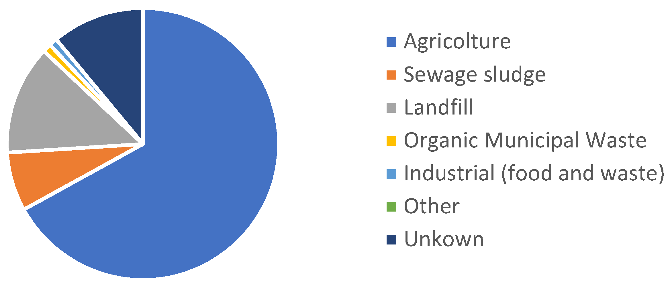
Thermochemical processes frequently operate in challenging environments characterized by elevated temperatures and pressures, leading to high levels of consumption. The system requires a substantial initial investment and setup due to the severe operating conditions and potential danger. Moreover, these procedures usually yield a range of chemicals, requiring a refining process. The primary benefit is the quick conversion process, which takes a maximum of minutes to complete [8]. Biochemical conversion technologies integrate biological and chemical processes. This process uses microbes and biological catalysts to convert biomass into gas, specifically carbon dioxide (CO2) and methane (CH4). It provides exceptional selectivity in transforming biomass into the intended final products. The integration of these two types of technologies results in reduced energy consumption, but it requires meticulous process control to prevent microbial death [9]. The selection of process technology is dependent upon the desired end product and the feedstocks supplied. This work is focused on the anaerobic digestion (AD) process, which produces biogas and can be upgraded into biomethane. AD can increase the value of decentralized biomass feedstocks by converting biogas into biomethane for chemical manufacturing, thereby fostering the growth of a new bio-industry [10]. Biomass is converted in specialized reactors, called digesters, by a series of metabolic actions carried out by microbial groups. The reactions progress through various phases: hydrolysis, acidogenesis, acetogenesis, and methanogenesis. Every phase is defined by the decomposition of intricate organic molecules into more basic ones. The outcome of the process is a gas mixture primarily composed of CH4 and CO2, with small amounts of N2, H2S, H2O, and VOCs. The influence factors on the output composition and energy content of biogas produced by anaerobic digestion are the type of biomass used as feedstock, operating temperature, operating pH, biomass loading rate, hydraulic retention time, and solid retention time [11]. Anaerobic digestion is highly adaptable and may treat a variety of biomass sources including agricultural wastes, animal by-products, sewage sludge, landfill materials, and the organic fraction of municipal solid waste (OFMSW). In Europe, the primary biomass utilized in biogas production, as indicated in the EBA report [12], is agricultural. Biogas can also be produced from landfills, although this method is less regulated and results in more fluctuations in the outcome. The biogas composition depends on the type of biomass used and the conditions and methods used during the conversion process, as can be seen in Table 1. By strategically choosing biomass feedstock and optimizing process parameters, biogas production efficiencies can be improved, making anaerobic digestion an even more appealing choice for generating renewable energy, boosting the CH4 content in the final product.
After generation, the biogas can be used directly in a combined heat and power system (CHP), or it can be upgraded into biomethane. The direct burning of biogas in the CHP system offers better environmental performance than an upgrading system [13]. Producing biomethane enables its injection into the natural gas grid for use in energy production or challenging areas like transport and buildings, as shown in Figure 2, resulting in reduced greenhouse gas emissions and the potential substitution of natural gas [14]. Different methods can be used to produce biomethane from biogas. Well-known technologies include water scrubbing (WS), chemical absorption (CA), organic scrubbing (OS), membrane separations (MS), and pressure swing adsorption (PSA). Cryogenic distillation (CD) is being considered as a potential alternative method to produce liquefied biomethane (LBM) and LCO2 as a byproduct in the future. Other methods are also being studied at a laboratory scale and are demonstrating promising results as biological upgrades. The selection of a technology depends on factors such as the composition of the incoming biogas, the system’s size, and the desired methane purity. Figure 3 illustrates the diffusion of the different upgrading technology in Europe, and it highlights that membrane separation is the predominant one.
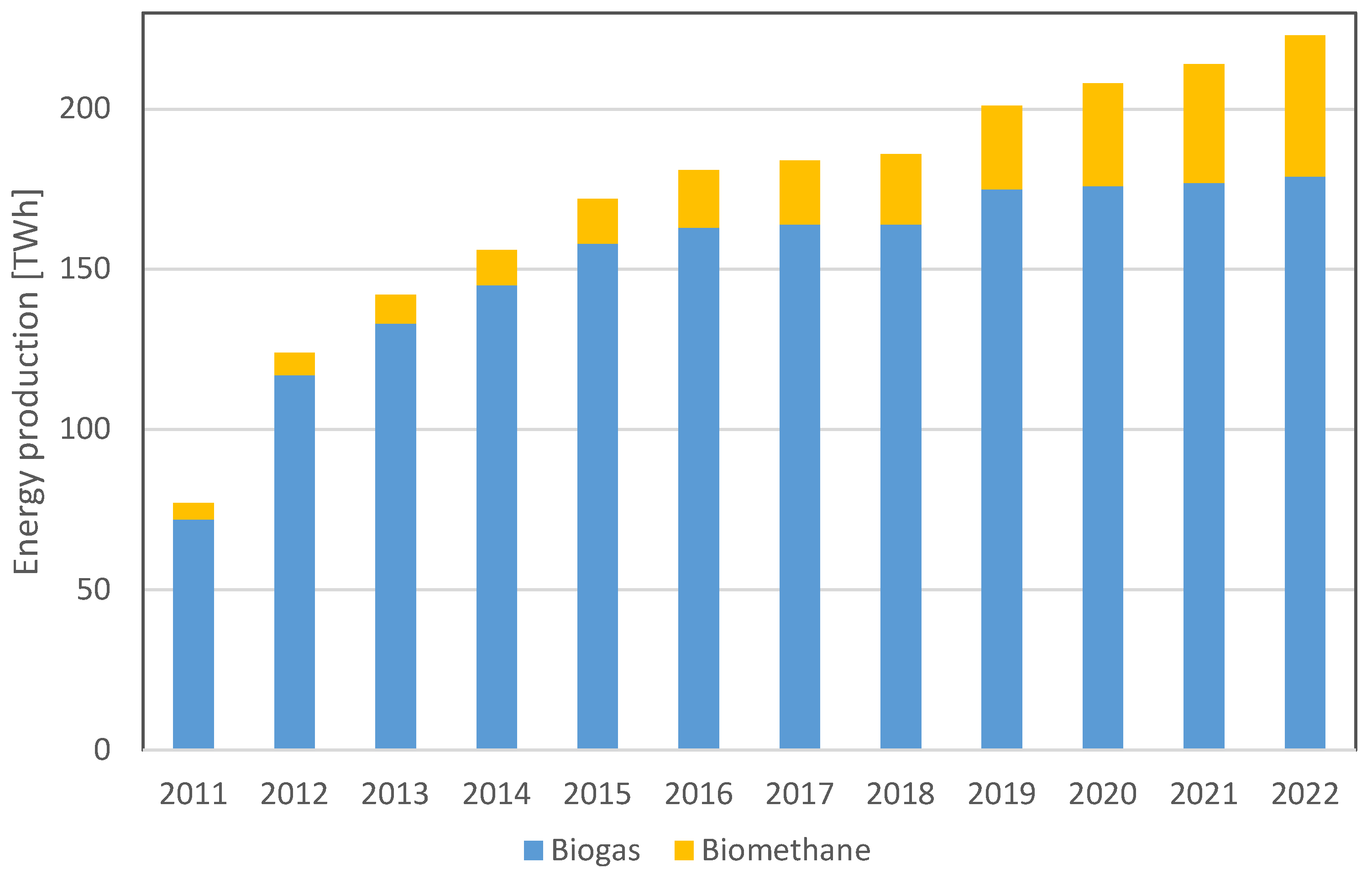
The biogas and biomethane business has been undergoing significant expansion in recent years due to substantial investments and favorable policies [15,16]. In 2022, biogas output reached 179 TWh, in accordance with rge EBA report [12], and biomethane production was 44 TWh, showing a 16% growth from 2021, as shown in Figure 4. The process of converting biogas into biomethane requires an initial cleaning step to exclude hydrogen sulfide, volatile organic compounds, and occasionally water. The presence of this biogas cleaning is related to the selection of the following upgrading technology.
This work is organized in three sections. In the following one, there is a concise overview of the cleaning procedures used to remove H2S, NH3, and VOCs. In the next section, a detailed examination of biogas upgrading technology is provided, with a primary focus on existing industrial-scale systems and closing with the one with promising growth. The last section includes a concise economic assessment focused on a typical Italian biogas producing plant aiming to transition into a biomethane producer. The main contributions in comparison to previous research and reviews on biogas upgrading systems are as follows: (i) the identification of distinct cleaning procedures, (ii) the specification of manufacturers for various technologies, and (iii) the contextualization of upgrading methods within a practical scenario.

2. Biogas Pretreatment before the Upgrading System: Cleaning Technologies

It is essential to follow the correct cleaning technique to separate H2S, NH3, VOCs, and siloxanes from CH4 to avoid damaging the upgrading system, considering the relative cost, potential danger, and compliance with EU norms [17]. The section is structured with the presentation of H2S removal at the top; then, the NH3 removal methods are presented, noting that these methods are generally similar to H2S removal but with variations in the substance employed to react with NH3. Following that, a concise overview is given on the potential technologies utilized for the removal of VOCs and siloxanes. The filters used are frequently modified to match customer needs and oversized to minimize maintenance and capitalize on economies of scale due to the technology’s moderate complexity and expense. Activated carbons used to remove H2S are often placed first to avoid interference from other chemical species and to avoid the formation of COS. This work does not primarily focus on the cleaning process, but it is essential to include it to understand the steps involved in upgrading biogas to biomethane.

2.1. H2S Removal System

There are two main categories of H2S removal systems: biofilters and bioscrubbers, distinguished by their operational mechanisms. Biofilters utilize a solid bed to support microbial growth, whereas bioscrubbers employ a liquid solution to remove H2S from the biogas; after this, the solution enters the reactor where the microorganisms activate the separation. The H2S removal process can also be distinguished based on the microorganisms responsible for the conversion. In Table 2, some examples can be seen with the relative references.

2.1.1. Biofiltration

Gas treatment involves exposing the gas to a biofilm in a fixed bed bioreactor, as can be seen in Figure 5. Biofiltration systems can be classified as either biofilters (BFs) or biotrickling filters (BTFs) and use a salt solution to keep the filters moist. In the BT design, the solution is injected internally into the filter. In contrast, in the BTF arrangement, the solution flows continuously; then, it is collected at the bottom and recirculates. The effectiveness of pollutant breakdown in biofiltration systems depends on variables such as packing materials, biofilm properties, and operational parameters [21]. Plastic supports or porous ceramics are typically utilized in BTFs; natural filter bed materials are commonly employed in BFs. The benefits of natural organic packing materials are low cost and easy availability. The main disadvantages compared to inert organic materials are compaction, which leads to channeling and a large pressure drop, as well as a shorter lifespan, often lasting fewer than five years [22]. DMT, and BiogasClean are some of the producers of this technology [23,24].

2.1.2. Bioscrubber

A bioscrubber (BS) is composed of two main components: an absorption tower that absorbs pollutants like H2S in water, and a bioreactor unit where microorganisms transform the pollutants into end products [25]. Bioscrubbers can also be adapted to remove mixed pollutants by adjusting the reactor’s design. This solution is highly effective in removing water-soluble contaminants and has the ability to operate throughout a broad spectrum of biogas compositions and perform an adequate cleaning process. BSs require a lot of maintenance and protective measures for dealing with secondary contamination from the liquid waste stream, and are operationally complex due to their biological nature [26]. Veolia and Paques are some noteworthy producers [27,28].

2.2. NH3 Removal System

The NH3 removal systems exhibit similarities to H2S removal systems, with the distinction lying in the specific bacteria type or substance employed to react with ammonia [29].
  • Bioreactor: Ammonia removal takes place in a bioreactor, whereas gas–liquid mass transfer occurs in a scrubber. Providing adequate time for gas-phase NH3 to interact with the scrubbing liquid enables NH3 to dissolve as NH4+ in the aqueous solution [29].
  • Biological ammonium oxidation: This is an anaerobic and exothermic process, so the temperature control is a crucial aspect of the technology. This approach is commonly used to treat wastewater with a high percentage of ammonia. It is frequently used for removing gaseous NH3 as well [30].
  • Bioconversion: This can be divided into two phases. Initially, bacteria convert NH3 into nitrite (NO2), as can be seen in Equation (1); then, NO2 is converted into nitrate (NO3), as illustrated in Equation (2).
    N H 3 + O 2 N O 2 + H 2 O
    2 N O 2 + O 2 2 N O 3
  • Ammonia acts as the electron donor in these bioconversion process, while CO2 serves as the carbon source and O2 functions as the electron acceptor. The pH has a crucial role in microbial development and the effective conversion of NH3 through mass transfer from the gaseous to liquid phase [30].
  • Biofiltration: Examples include BFs and BTFs. Biofiltration is similar to the process described in the H2S removal section. Biofilters are mainly utilized to address exhaust air with elevated levels of NH3 emissions from agricultural and livestock operations. [31].

2.3. Siloxanes and VOCs Removal

Siloxanes are polymers that consist of Si-O-Si bonds, with organic groups (such as methyl or ethyl) attached to the Si atom. The substance possesses exceptional physico-chemical characteristics, such as a low surface tension, high thermal stability, and strong resistance to environmental oxidation. Siloxanes undergo volatilization and enter the biogas as volatile methyl siloxanes (VMSs) during anaerobic digestion.
Volatile organic compounds (VOCs) are organic compounds that readily evaporate at room temperature due to their high vapor pressure [32]. VOCs are accountable for the aromatic characteristics of smells, as well as the presence of pollutants. While the majority of VOCs do not pose immediate toxicity, they can have adverse long-term health effects. However, certain VOCs can be hazardous in short time to human health and can also cause harm to the environment. Various factors influence the biodegradability of VOCs, including the presence of a well-adapted microbial community, its capability as a carbon source, and the transfer of mass between gas–liquid and liquid–biofilm phases. These parameters are affected by VOC properties like solubility, molecular size, and biodegradation order, and the interactions between compounds where the presence of one can impact the removal of others.
The mainly used physical–chemical methods to remove both siloxanes and VOCs include activated carbon adsorption, phosphoric acid absorption, and water washing [17,33,34,35,36,37,38,39]. Biological methods such as biofiltration methods to remove siloxanes and VOCs have primarily been evaluated in laboratory settings. The bioreactors exhibited a low removal efficiency in the majority of cases due to extended gas residence times. Among the mentioned bioreactor configurations, BTFs exhibit superior VOC removal efficiency. Furthermore, BTFs provide effective management in terms of regulating nutrient delivery, pH levels, and the elimination of harmful byproducts. Some of the producers of this filtration system are Desotec [40] and Norit [41].

3. Upgrading Technologies

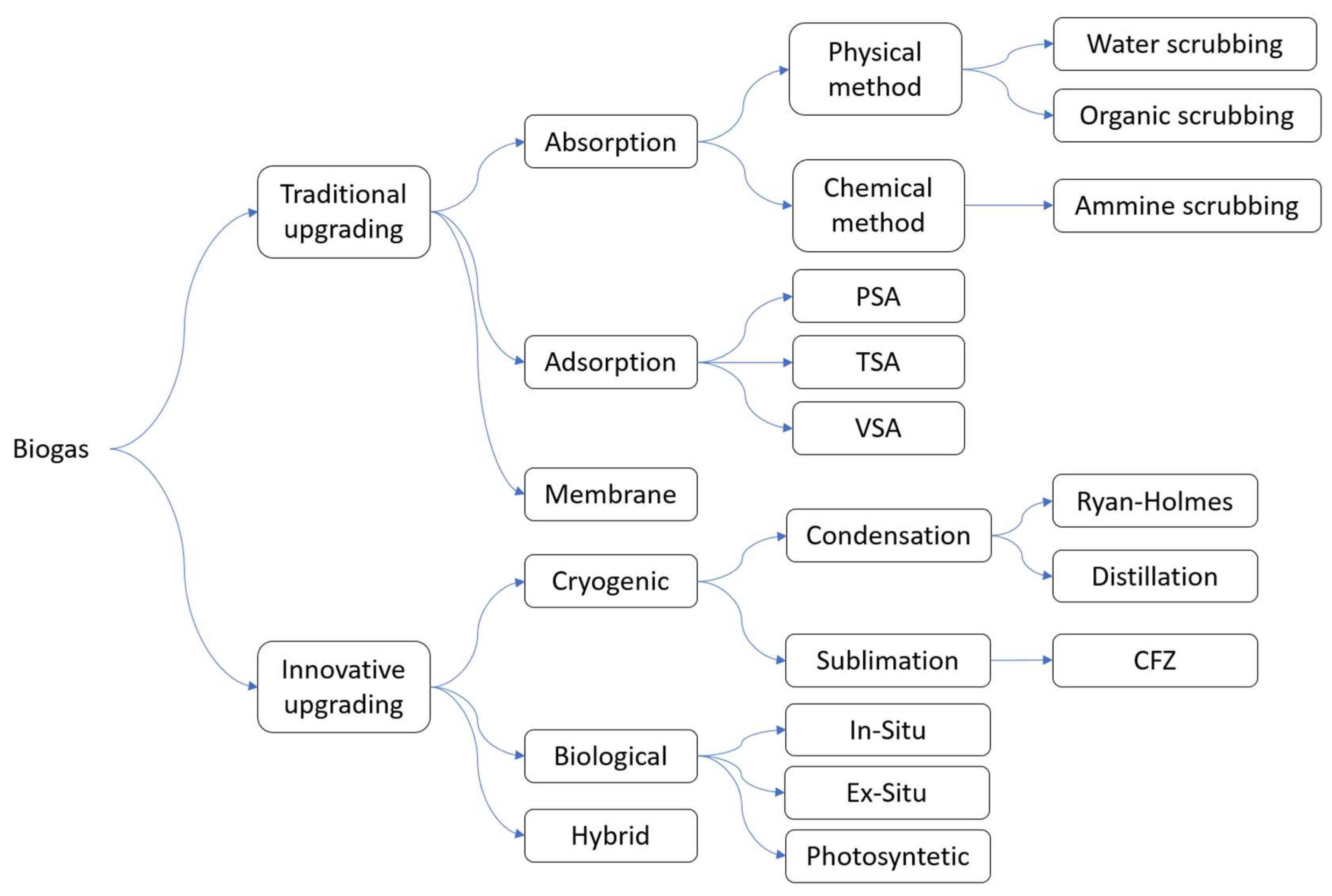
The separation between the carbon dioxide and methane can be accomplished by a number of technologies, including established ones like water scrubbing (WS) and membrane separation (MS) and novel ones like biological processes and cryogenic distillation (CD). Nowadays, the most commonly used technology for the upgrading process is separation via polymeric membranes, with other alternatives taking the remaining market share, as can been seen in Figure 3. Europe has experienced a significant rise in the presence of biogas upgrading pants, as shown in Figure 4, utilizing various technical solutions to reach the quality and efficiency of biomethane production. Figure 6 illustrates a panoramic view of the different upgrading technologies divided based on the type of separation performed. Conventional methods including adsorption, absorption, and membrane separation are more cost-effective and practical than newer technologies due to their maturity. However, several research and development companies are working on techniques like cryogenic and biological approaches to bridge the gap with conventional solutions [42]. The main advantage of the cryogenic process, for example, relies on the direct production of LBM (liquefied biomethane) and pure liquid CO2 as a byproduct. Condensing biomethane is a high-energy process that is deemed necessary under certain circumstances. For instance, plants without a gas grid connection or specialized sectors such as heavy road transport must utilize condensing biomethane in order to transport it. Instead, the biological upgrading process enhances methane output by converting CO2 into CH4 using H2. The primary constraint of this technique is the high expense associated with producing hydrogen. Only green and yellow hydrogen are considered acceptable for usage due to their low environmental impact [43]. The first is derived from water electrolysis powered by renewable energies, while the yellow one is generated by solar power. Some upgrading technologies release CO2 since it comes from a biogenic source, which means it is not considered an emission on the greenhouse gas (GHG) balance. The problem is in the presence of methane traces in the CO2, leading to financial losses for businesses and posing a significant environmental hazard due to methane’s high Global Warming Potential (GWP) value [44]. So, it is crucial to eliminate methane from the vented offgas using three possible methods to prevent the direct injection of CH4 into the atmosphere. The first and simpler method involves passing the offgas via a torch where methane is oxidized to form CO2 through burning. The second method is only feasible if the production plant already has a CHP system in place to combust biogas. This solution involves incorporating the offgas into the biogas feed of the CHP for combustion. The final solution involves a catalytic oxireduction process carried out by technologies such as a regenerative thermal oxidizer (RTO) following the reaction, as shown in Equation (3) [45].
C H 4 + 2 O 2 C O 2 + 2 H 2 O

3.1. Absorption

The absorption technologies can be categorized into two types: physical methods such as water scrubbing and organic solvent scrubbing, or chemical methods such as ammine scrubbing.

3.1.1. Water Scrubbing

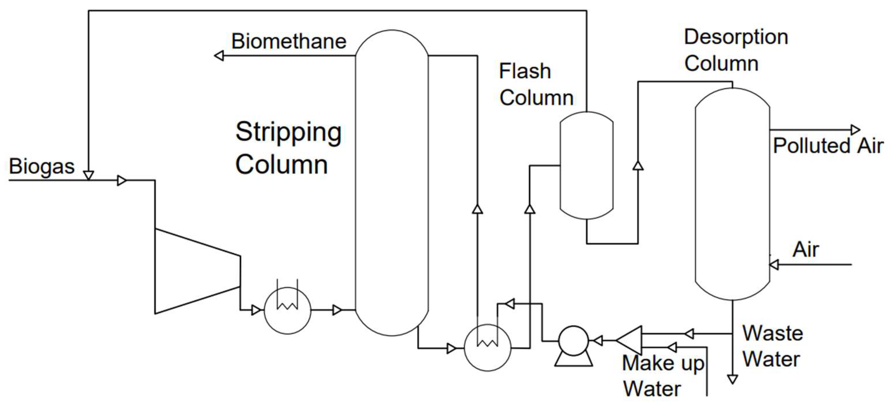
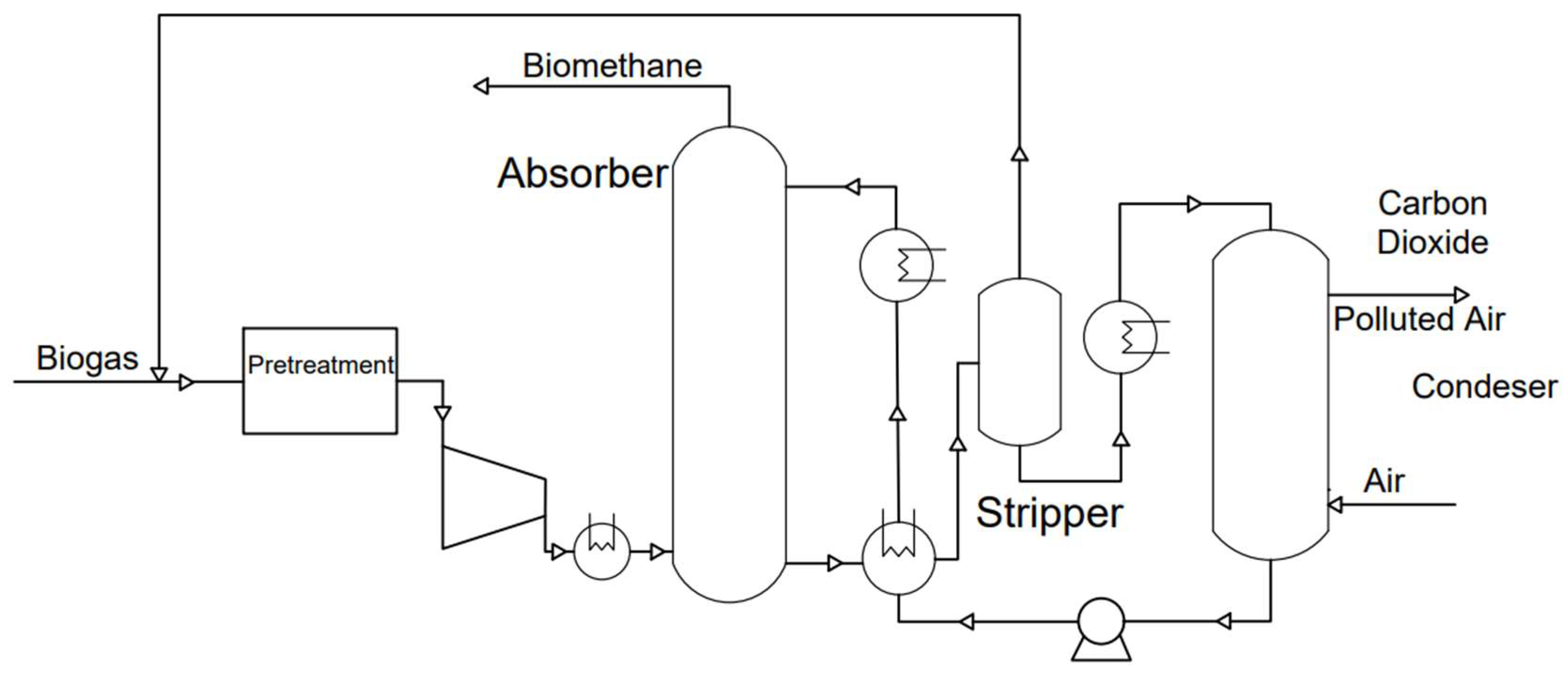
Water scrubbing (WS) is a widely used physical absorption process that takes advantage of the varying solubility levels of different biogas components in water. The greater solubility of CO2 in water compared to CH4 is mostly due to its polarity and it is determined by different partial pressures following Henry’s law. At 25 °C, the solubility of CO2 in water is approximately 26 times higher than that of methane [46]. However, solubility is temperature-dependent, with an increase in temperature usually leading to a decrease in solubility [47]. The water scrubber is the most impurity-resistant upgrading technology available on the current market [48]. For this reason, biogas is directly fed from the digester without undergoing a cleaning process. The biogas is pressurized to 6–10 bar and then sent into the adsorption column from the bottom of the tank [49], while water is introduced from the top, as shown in Figure 7. The water stream, which is rich in carbon dioxide, acidic elements, and some trace of methane at the bottom of the adsorption column, can be either discharged or regenerated. In sewage treatment, a single pass scrubbing design is often used, and the water is discharged after cleaning. On the other hand, this stream is commonly regenerated in a separate column during the biogas upgrading process in anaerobic digestion. The regeneration phase is essential for this technology upgrade because of the significant amounts of water needed. The regeneration process is firstly carried out in a flash column by reducing the pressure around 2–4 bar, which leads to the release of methane due to the decrease in partial pressure. The methane content in the gas stream [50] released during the regeneration phase can reach values up to 18%, so the produced gas phase is recirculated to the biogas compressor to drastically reduce the methane slip. The liquid stream containing water, carbon dioxide, carbonic acid, ammonia, and volatile organic substances is subsequently fed into the desorption column. Here, a process of stripping using ambient air is employed to separate water from other chemical species. The gas stream at the outlet, containing the majority of impurities and CO2, is treated to minimize emissions typically using a RTO. The aqueous solution, primarily consisting of water, is cycled back to the absorption column: a small portion is purged to prevent an overabundance of contaminants and replaced by make-up fresh water. The countercurrent flow of biogas and water facilitates mass and heat exchange, minimizing the energy consumption as well as the methane loss. To increase the exchange area, both columns are often filled with a packed bed. Sometimes, fungi or other microorganisms may grow on this packing material, potentially causing clogs in the water scrubber [48]. The primary factors influencing the proliferation of this activity are water pH, temperature, and biogas composition [51].
The pressure of the absorption column is the most important parameter because it determines the purity of the biomethane. The pressure difference between the two columns is critical for methane recovery. To increase the column separation efficiency, it is crucial to increase its height: this can be performed by adding theoretical plates or increasing the HETP (Height Equivalent to a Theoretical Plate). The diameter does not directly affect the efficiency of the separation, but it is essential for the proper fluid dynamics that influence the column’s correct operation. The two main hydraulic possible issues are flooding due to excessive gas flow, which causes liquid accumulation, and entrainment caused by high gas velocity, which produces preferential routes [52]. The required amount of water can be determined using the following equation, which is not influenced by the pH [48].
Q w a t e r l h = Q b i o g a s × C O 2 K H × p C O 2
where Qbiogas is the total biogas flow, %CO2 is the molar percentage of carbon dioxide in the raw biogas, PCO2 is the partial pressure of carbon dioxide in the absorption column, and KH is Henry’s constant. To upgrade 1000 Nm3/h of raw biogas, a water flow rate of 180 to 200 m3/h is typically required, depending on the pressure and water temperature. The consumption cost can be divided as follows: 0.10–0.15 kWh/Nm3 for biogas compression, 0.05–0.10 kWh/Nm3 for water pumping, and 0.01–0.05 kWh/Nm3 for biogas cooling after compression [48]. The achievable methane purity is approximately 97% with a methane recovery rate of about 98% [53]. The purity of biogas is significantly affected by the presence of oxygen and nitrogen, as most of them are extracted together with the biomethane stream.
The primary advantage of water scrubbing is its simplicity; as well, it does not produce any toxic byproducts, leading to more simplified plant management. However, there are several limitations associated with water scrubbing: the main ones are the water consumption and water treatment.

3.1.2. Organic Physical Scrubbing

The organic physical scrubbing process functions similarly to water scrubbing, as can be seen in Figure 8, with the main distinction being that biogas is absorbed by an organic solvent instead of water. The change in working fluid is due to the higher solubility of carbon dioxide in the organic solvent compared to water [54], leading to a significant decrease in the amount of solvent required. Organic physical scrubbing requires the use of smaller column widths due to reduced organic solvent flow rates compared to water scrubbing. While this outcome is generally advantageous, it is essential to ensure a minimum diameter for small plants to guarantee effectiveness. The organic solvent needs to be heated in the desorption step and cooled before the absorption step; this double thermal treatment is one of the major differences compared to water scrubbing, leading to an increase in the complexity of controlling the plant operations. In addition, raw biogas has to be cleaned with an activated carbon bed to remove hydrogen sulfide, ammonia, and siloxanes from biogas to protect the organic solvent. The gas is pressurized to 7–8 bar and subsequently cooled to approximately 20 °C before being introduced into the column [55]. Decreasing the temperature raises the solubility of carbon dioxide gas because of the temperature’s impact on Henry’s constant. The biogas is introduced at the column’s base, and the organic solvent is introduced at the top to generate a countercurrent flow, promoting heat and mass transfer. To increase the exchange area and achieve the required separation factor, the column is filled with packing material. The organic solvent, together with carbon dioxide, exits from the desorption column and enters the flash column. In the flash column, the pressure is decreased around 1 bar [49], causing the dissolved methane to be released and recirculated back to the compressor. The solvent viscosity impacts the distillation column pressure. The increased temperature decreases the viscosity, lowering the column backpressure and allowing higher flow rates. Table 3 lists the value for some solvents [56]. The methane slip is influenced by the pressure in the desorption column and the composition of the biogas. The organic solvent needs to be regenerated by heating it to approximately 80 °C and then transferring it to the desorption column [57]. After regeneration, the organic solvent is cooled to the required temperature in the absorption column. To prevent excessive CO2 equivalent emissions, a technology such as a torch, a RTO, or a CHP system is usually required to remove methane from the offgas.

3.1.3. Chemical Absorption

Amine scrubbing is the primary method for upgrading through absorption, involving a reagent that forms chemical bonds with CO2 molecules. Producing stable molecules by reacting carbon dioxide with amine compounds is crucial for effective CO2 removal. The most commonly utilized amines in chemical absorption upgrading systems are MEA, MDEA, DEA, and DGA [46]. Based on these results [61], the most cost-effective and energy-efficient approach is DGA. Biogas pretreatment to remove H2S is crucial to prevent the degradation of amine, which can lead to economic and environmental damage. Following that, the biogas is compressed to reach the operational pressure of the absorber at around 2 bar [49]. The pressurized stream enters the column from the bottom and interacts with the amine solution. An exothermic reaction takes place within the absorber, increasing the temperature of the solution. Absorption is thermodynamically favored at low temperatures but kinetically favored at higher temperatures [48]. So, an equilibrium must be achieved between the reaction time, which affects the column dimension, and the reaction efficiency. The temperature, a crucial operational factor, varies between 20 °C and 65 °C, depending on the type of amine chosen [55]. The gas exiting the first column is mostly methane, while the liquid product from the lower section, primarily consisting of amine and CO2, requires regeneration to recover the amine solution. The liquid stream enters HX-01, as shown in Figure 9, where it is preheated by the regenerated solution. The ammine–CO2 solution is then heated in the desorption column with a reboiler. The solution partially evaporates and leaves the top of the column to be cooled down in HX-03. Both columns are usually filled with packing materials to maximize the exchange area. Due to the high pH of the solution caused by the basic amines, the possibility of bacteria development on the packing material is minimal. The last step of the process is devoted to the amine condensing and separation from the CO2, which is subsequently released into the atmosphere. The regenerated amine solution from the bottom of the desorption column is cooled using heat exchangers HX-01 and HX-02 before entering the absorber column.
The amine is added in a large excess compared to the stoichiometric value, which is 4–7 times greater on a mole basis, to prevent equilibrium limitations in the reaction [48]. The amine selection process is crucial as certain amines may exhibit lower stability, deteriorate more rapidly, or require more energy input during solvent regeneration [62]. The amine solutions are characterized by distinct benefits and drawbacks, which are illustrated in Table 4. As can be seen, there are amines such as DEA, which exhibit a significant absorption capacity but also undergo substantial degradation under certain working conditions. Ammine scrubbing is highly effective in removing CO2, resulting in the production of biomethane with methane concentrations that usually surpass 95% [57]. Electricity consumption varies depending on operating conditions, ranging from 0.12 kWh/Nm3 to 0.21 kWh/Nm3. The stripper column requires heat to regenerate the amine, with a heat demand of approximately 0.55 kWh/Nm3 of the raw biogas [48].

3.2. Adsorption

The adsorption process relies on the size of biogas molecules, the diverse porosity of adsorbent materials, and the unique intermolecular forces between the chemical components in the biogas and the porous material [50]. The adsorbent material is made of extremely porous materials with distinct pore shapes, allowing the selective adsorption of some gas molecules while rejecting others based on their size and surface affinity. Adsorption technologies are similar, with variations in the regeneration technique of the adsorbent material. Regenerating the adsorbent material by depressurizing above the atmospheric pressure is known as pressure swing adsorption (PSA), regenerating the adsorbent material by heating the process is known as temperature swing adsorption (TSA), and regenerating the adsorbent material by reducing the pressure below the atmospheric pressure is known as vacuum swing adsorption (VSA).

Pressure Swing Adsorption

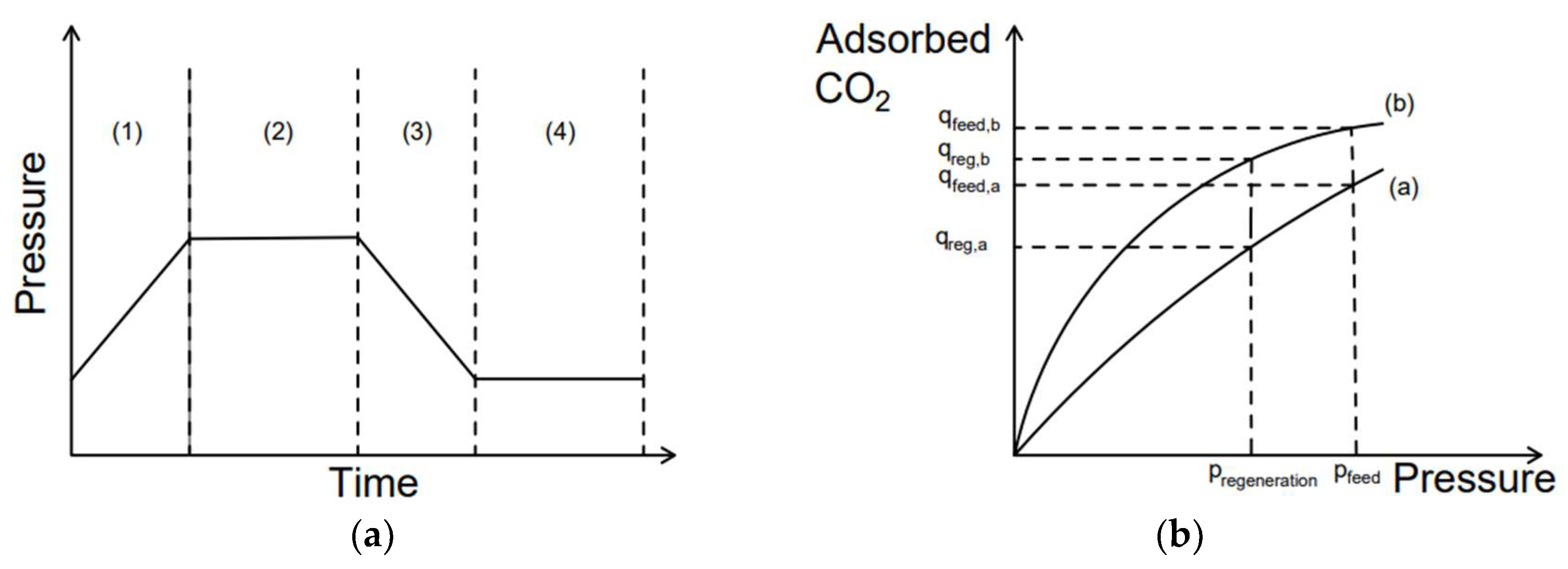
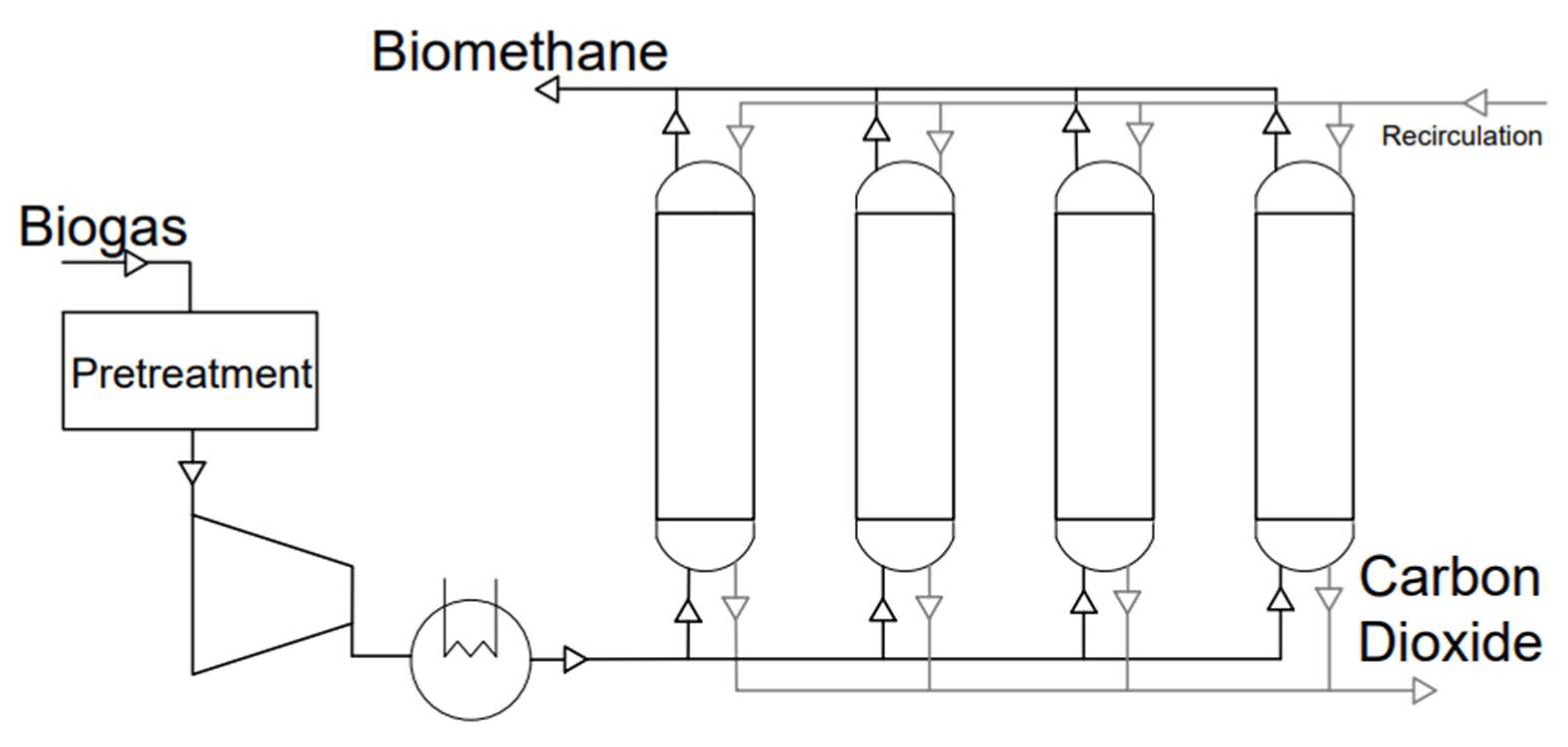
Raw biogas is first purified by eliminating hydrogen sulfide, VOCs, siloxanes, and H2O; then, it is pressurized and directed into an adsorption column where carbon dioxide is captured while methane passes through. After the column material is saturated with carbon dioxide, the pressure is decreased, which enables the carbon dioxide to be released and directed into an offgas stream. The columns’ operational cycle follows the Skarstorm cycle [65], which includes four stages: pressurization, feed, depressurization, and purge, as can be seen in Figure 10a. Several columns are necessary for continuous flow in the batch process. The relationship between gas adsorption and pressure for a particular adsorbent is depicted in Figure 10b. An ideal adsorbent material should show a substantial difference between qfeed and qregeneration, taking into account the pressurization expenses, where q is the volume of CO2 that can be adsorbed at those conditions. Usually, to minimize methane loss, the gas released during the regeneration phase of a column is utilized to pressurize a cleaned column to take advantage of the remaining pressure and decrease the energy usage [48]. Increasing the number of columns can provide additional design possibilities to improve the system energy efficiency, but it also results in increased complexity and costs. A typical layout is showed in Figure 11. The adsorbent is a porous material created with a large specific surface area to improve gas interaction. Activated carbons, natural and manufactured zeolites, silica gels, carbon molecular sieves (CMSs), and MOFs are common adsorbent materials [49]. Effective adsorbent materials must have activity and selectivity for carbon dioxide, be non-toxic, and demonstrate long-term stability. There are two main types of adsorbent materials: equilibrium adsorbents, such as activated carbons and zeolites, and kinetic adsorbents, like Cu-MOF. The first material has a greater capacity for carbon dioxide adsorption than methane, while the second material adsorbs carbon dioxide at a faster rate, reducing the cycle time, as can be seen in Table 5. The gas produced during the blowdown process contains methane, which can be managed using several methods, such as a torch, RTO, or CHP system. The primary benefits of the PSA method include the lack of chemical issues and its dry nature, which eliminates the concern of contaminated wastewater. The primary drawback is the loss of methane and electricity usage. The electricity consumption of the PSA system for upgrading ranges from 0.15 to 0.3 kWh/Nm3 for raw biogas, with an additional 0.17 kWh/Nm3 for drying and the final compression of the output gas. Using a catalytic oxidizer increases the energy requirement, potentially reaching around 0.3 kWh/Nm3 [48].

3.3. Membrane Separation

This upgrading process is based on the different diffusivities of molecules through a porous media. The biogas feed is separated into permeate and retentate streams within the membrane module. The retentate is the gas stream rich in methane that is retained by the membrane, while the permeate is the gas stream containing carbon dioxide, oxygen, and humidity that permeates through the membrane, as can be seen in Figure 12. Unlike larger molecules like methane, carbon dioxide can penetrate the membrane more easily because of its molecular size.
The penetration rate is primarily determined by the molecule size, the hydrophilicity of the molecules, and the pressure difference between the two side of the membrane. Polyimide and cellulose acetate-based membranes are identified as the most appropriate commercial membranes for separating biogas [69]. Before the membrane upgrading, all contaminants in the biogas must be removed to avoid membrane degradation, which could result in system shutdown and costly replacement. An activated carbon bed is frequently utilized to remove hydrogen sulfide, ammonia, siloxanes, and volatile organic compounds. After this pretreatment, the biogas is compressed to a pressure between 6 to 20 bar and then chilled to reduce the dew point and remove excess humidity [49]. The operating pressure varies in accordance with the CH4 purity, depending on the intake composition during operation. It is essential to check for any oil residue after compression, as contact between the membrane and oil can greatly reduce the membrane’s lifespan, which usually ranges from 5 to 10 years [48]. The biogas is directed into a membrane reactor composed of multiple membranes which are module connected in a series. Various membrane configurations have been studied [70], but the two main types utilized by commercial plants are shown in Figure 13. In the configuration depicted in Figure 13a, the permeate from the first module is released while the retentate proceeds through a subsequent reactor. The permeate leaving the second reactor contains carbon dioxide with consistent traces of methane and is typically recirculated to the biogas compressor. The retentate stream contains methane with a purity usually exceeding 97%. This configuration can achieve methane recovery between 95% and 98% [50]. Figure 13b shows the second configuration with an extra reactor linked to the permeate of the first reactor. The third reactor produces offgas with a lower methane content, and the retentate is usually recirculated with the permeate from the second reactor. The alternative arrangement guarantees methane purity levels higher than 97% and methane recovery rates ranging from 99% to 99.5% [71]. Various membrane compositions offer a wide range of features as permeability or selectivity, as shown in Table 6, allowing for multiple designs. So, the membranes which have higher selectivity are used for the last separation step, and the membranes with higher permeability are chosen for the first stage of separation.
This technology provides benefits including great selectivity, low energy consumption, scalability, and functioning without the requirement of chemicals. Nevertheless, some disadvantages are the expensive initial investment and the membrane deterioration and vulnerability. The electrical energy usage for biogas upgrading using state-of-the-art membrane technologies is between 0.3 kWh/Nm3 and 0.5 kWh/Nm3 [57].

3.4. Cryogenic Separation

There are three main methods of cryogenic separation: two include the condensation of carbon dioxide, while the third is based on its sublimation. The cryogenic distillation process and Rayan–Holmes method involve compressing biogas and lowering the temperature to take advantage of the different boiling points of methane and carbon dioxide for separation. The controlled freeze zone (CFZ) uses the solidification of carbon dioxide at atmospheric pressure to separate it from methane in the biomethane production [73]. The systems indicated for removing CO2 from CH4 are costly and technologically complex. They are typically adaptations of technology originally developed for natural gas refining, like the CFZ prototype created by Exxon Mobile [74,75].

3.4.1. Controlled Freeze Zone (CFZ)

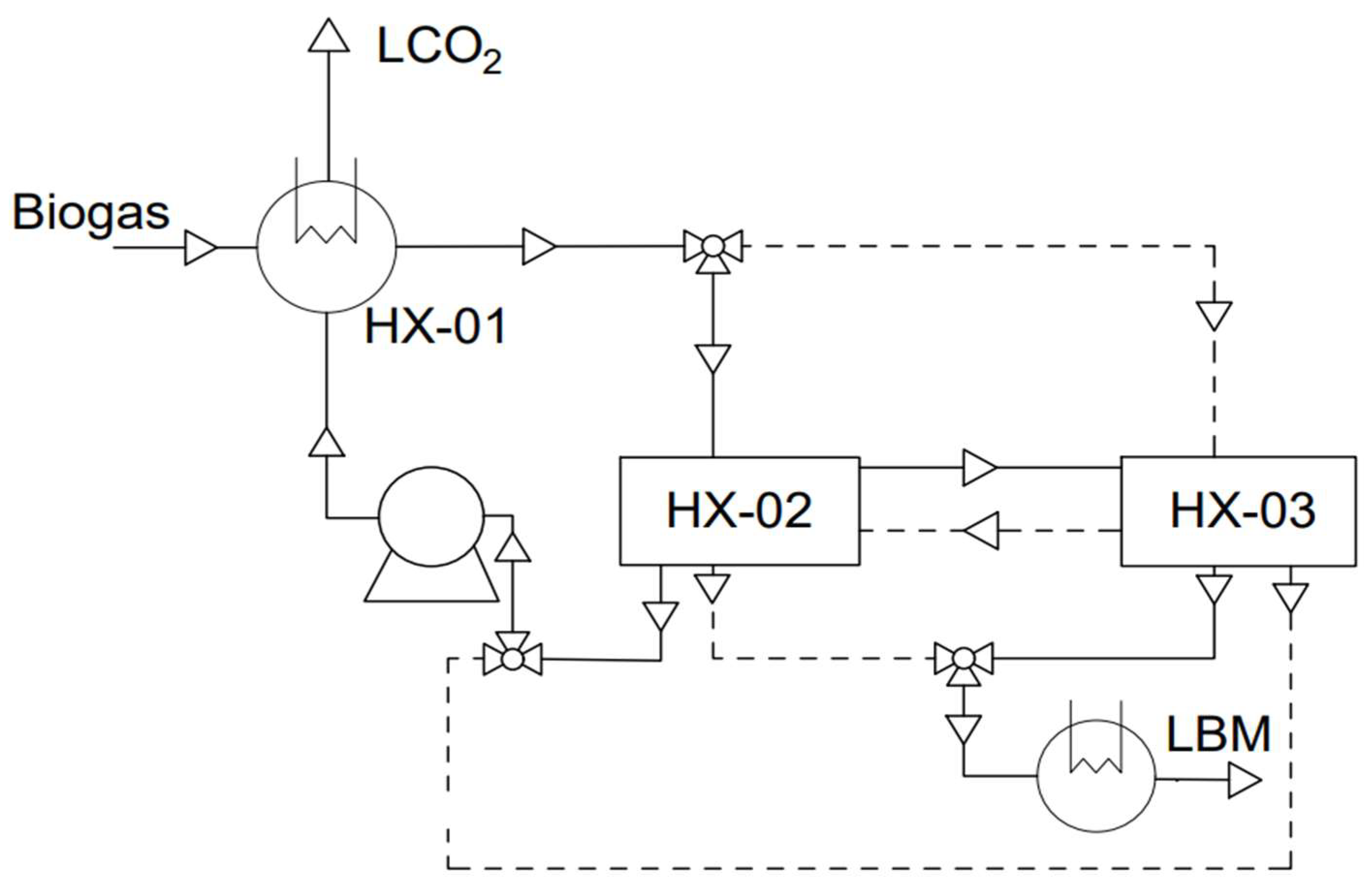
Prior to the upgrading process, the biogas needs to be cleaned and dehumidified. This last step is crucial to avoid the water freezing and damaging the equipment. Figure 14 shows the schematic of the process that mainly consists in a heat exchanger network: the main step is carried out with two or more heat exchangers with the same design to control the solidification of CO2. The heat exchangers HX-02 and HX-03 have the same configuration and during the process they switch between the sublimation and regeneration phase: Figure 14 shows heat exchanger HX-02 in the recovery phase and HX-03 in the sublimation phase. The dashed lines represent the streams when there is a reversal of the roles of the exchangers. During the regeneration phase, the biogas is precooled in the heat exchanger HX-01, heating up the solidified carbon dioxide and melting it into a liquid phase at the same time. The resulting biomethane is then cooled using an anti-sublimation heat exchanger to solidify the carbon dioxide and produce biomethane with a CO2 level of approximately 50 ppm. This approach has an advantage over the other cryogenic separation methods as it enables a lower methane content in solid CO2 than in liquid carbon dioxide, leading to decreased methane slip. The process is batch-oriented and requires heat exchangers to minimize the cycle time because of CO2 solidification, resulting in a significant increase in investment costs due to the specific heat exchanger design [74].

3.4.2. The Ryan–Holmes Process

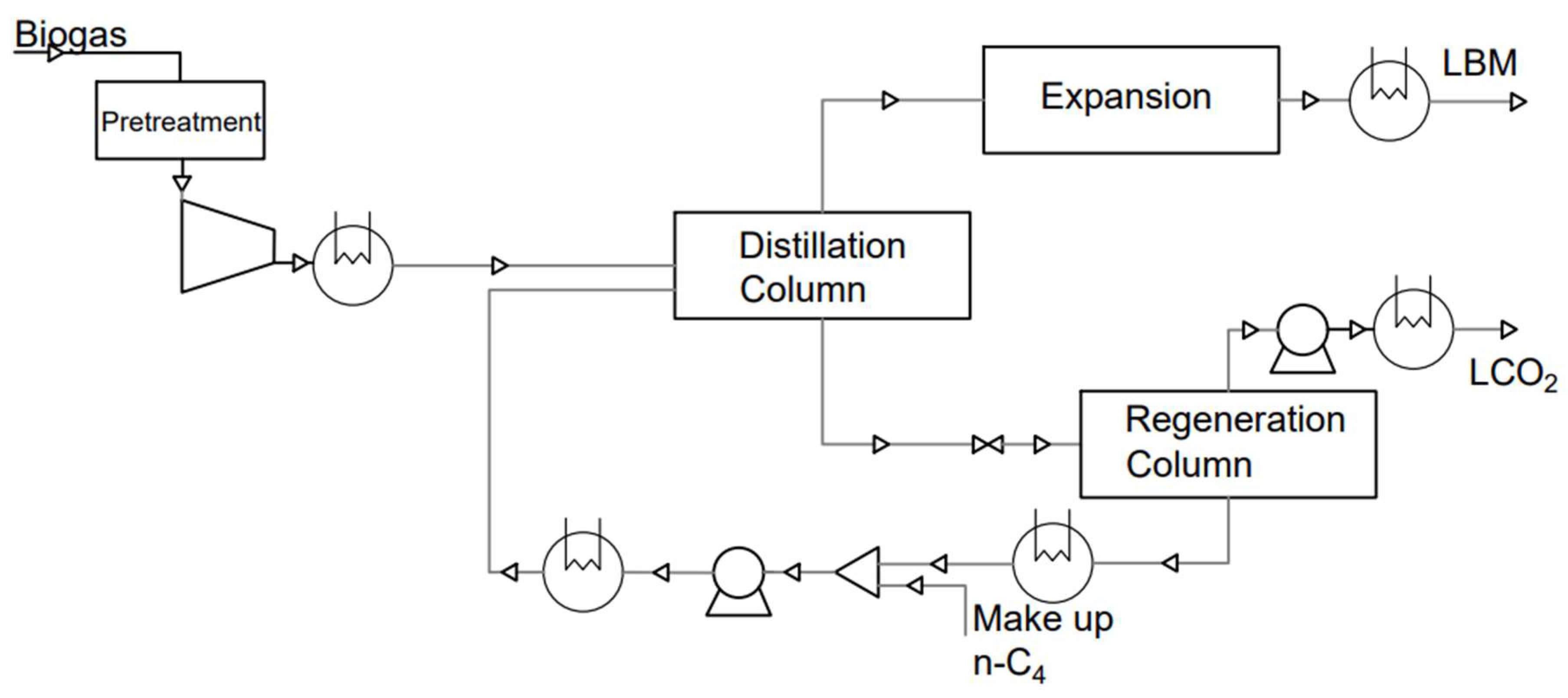
The biogas is pressurized to approximately 40 bar following an initial purification procedure and dehumidification. Heavy hydrocarbons, typically n-butane, are introduced into the extractive distillation column to prevent the solidification of carbon dioxide during the cooling process. The column yields two outputs: a methane-rich stream with trace amounts of carbon dioxide (about 80 ppm) and a stream mostly composed of carbon dioxide and butane at the bottom. The methane-rich stream undergoes expansion and condensation to separate the oxygen and nitrogen. A lamination method is utilized on the CO2 stream, followed by regenerative distillation to separate butane from carbon dioxide. This process is illustrated in the Figure 15. The regeneration process produces two streams: mostly pure liquid carbon dioxide and primarily liquid butane, which is subsequently pumped and returned to the starting column. A makeup butane is used to compensate for the loss during the cycle. This method is unsuitable for producing food-grade CO2 since it contains trace amounts of butane [76].

3.4.3. Cryogenic Distillation

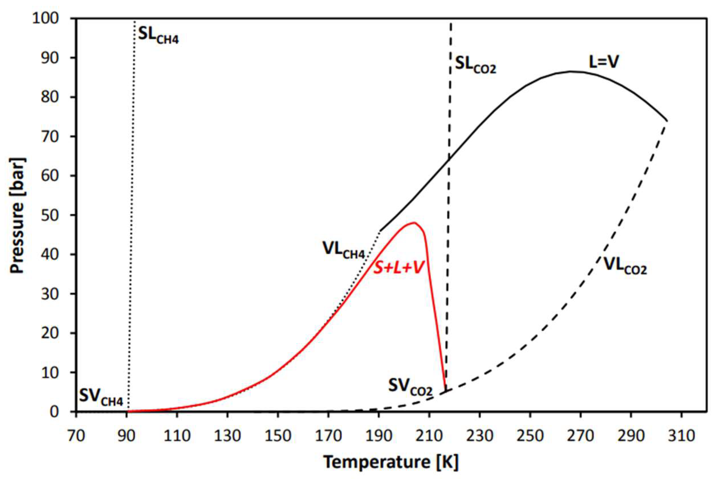
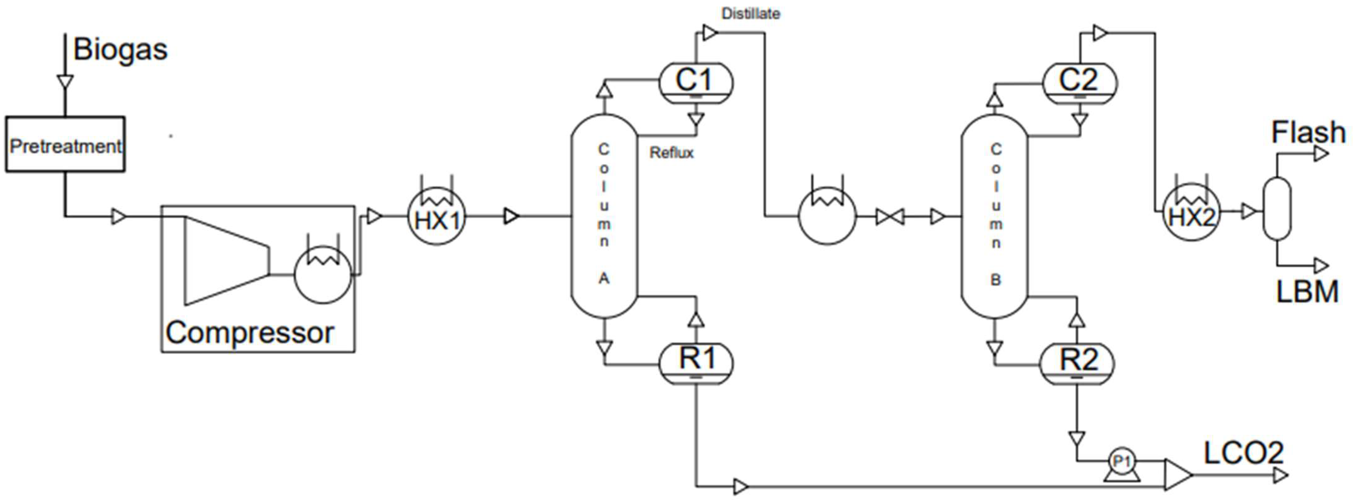
In cryogenic distillation, the biogas is first cleaned of H2S and dehydrated. If the plant aims to produce standard food-grade carbon dioxide, it is essential to remove siloxanes and VOCs as they tend to blend with liquid carbon dioxide due to their boiling point. After the initial cleaning process, the biogas is compressed to above 50 bar to exceed the pressure at which solid carbon dioxide forms, as can be seen in Figure 16. The pressurized stream is cooled prior to entering the distillation column through the heat exchanger HX-01 in Figure 17 [77]. After that, the biogas is introduced in the distillation column. It can be introduced in the middle, if the stream is in a two-phase state, or from the bottom, if it is in the vapor phase. The gas phase rises inside the column until reaching the condenser at the top, where it is cooled with a partial transition into the liquid phase.
The liquid stream flows down the column in counterflow and the gas stream improves the mass and heat exchange. The column is usually packed with packing material to maximize the exchange area and minimize the column dimension. Two products exit from the column: a stream consisting primarily of pure carbon dioxide at 50 bar and around 14 °C from the bottom, and a stream with a significant methane concentration, reaching up to 96% according to a prior study [78], at 50 bar and −76 °C from the top. The ability to improve separation is limited by the separation factor, which is influenced by the minimum temperature that cannot be decreased further to avoid dry ice formation. A second distillation column is necessary to meet the methane purity standards set by state regulations [79,80,81]. The main components at the top column output are methane, oxygen, and nitrogen if present in the biogas, while the bottom output is purely carbon dioxide. Based on the final use of biomethane, it can be mandatory to condense methane in order to separate it from oxygen and nitrogen based on their distinct boiling points. So, the methane flow is cooled and then expanded is enthalpically to take advantage of the Joule–Thomson effect and produce liquid biomethane (LBM). These systems have the advantage of achieving high purity levels in biomethane and allowing for the utilization of carbon dioxide. However, these systems have additional drawbacks such as significant initial investments, high energy consumption, and the need to thoroughly remove water before introducing biogas into the system. If the plant’s goal is to produce LBM, this technology can be compared to other upgrading processes. Furthermore, the liquid carbon dioxide (LCO2) byproduct is gaining market value based on the carbon credit price [82]. Some preliminary calculations have been carried out due to the lack of data on how the distillate composition is affected by the presence of O2 and N2 in the biogas.
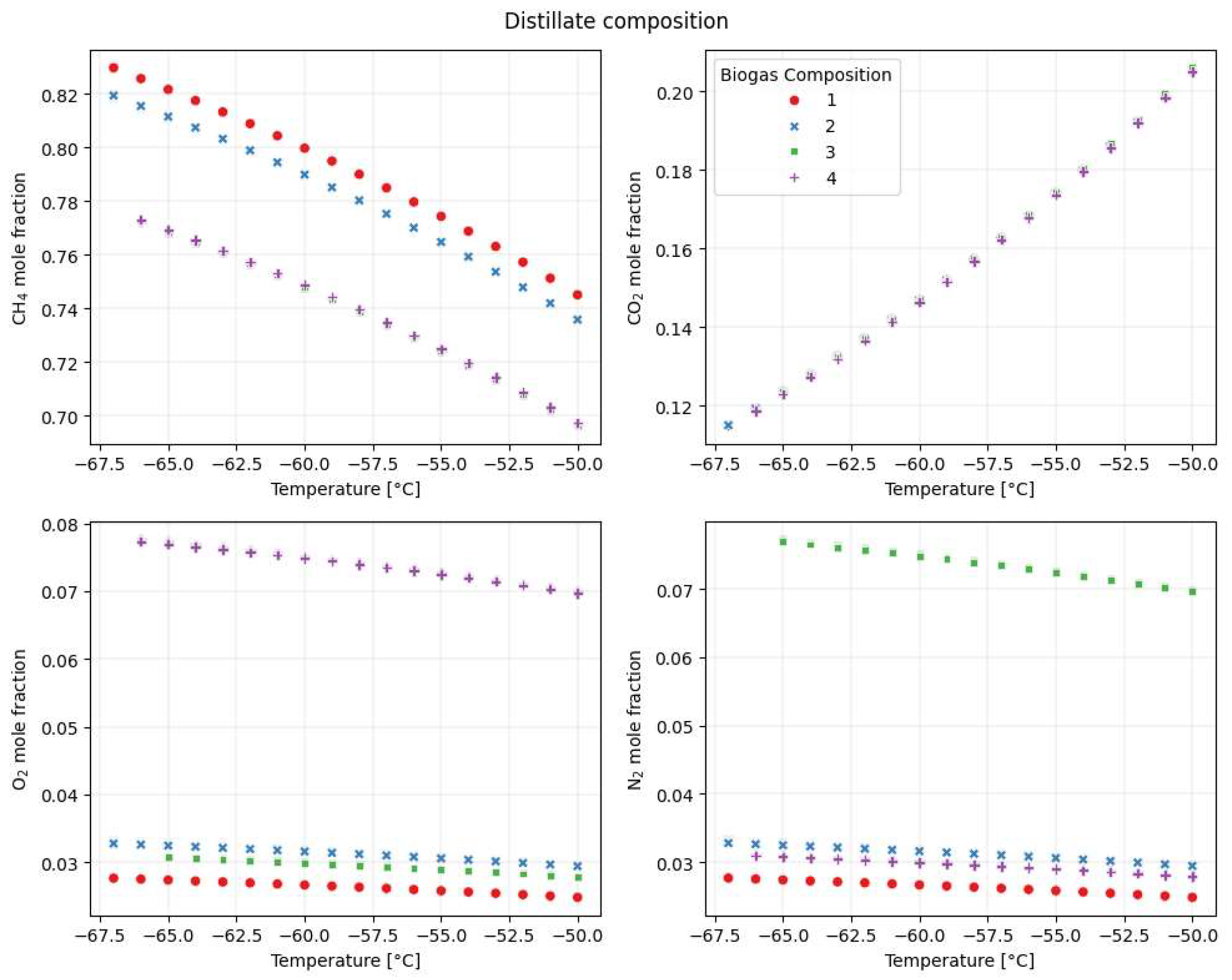
The analysis is focused on the influence of impurities in biogas composition and condenser temperature on the cryogenic single-column distillation. The purpose of this investigation is to examine how specific parameters affect the concentration of CH4 in the distillate and its flow rate. The parameters considered include the condenser temperature, reflux ratio (defined as the ratio of reflux molar flow to distillate molar flow), column pressure, number of column stages, and biogas composition. The range limit for the variables are derived from the literature previous cited [78,79,80,81] and are presented in Table 7. The biogas composition is altered by replacing one specified component from CH4, N2, and O2, with CO2 being determined by the balance difference. The compositions used are detailed in Table 8. The simulations are performed using Aspen Hysys V14 [83] and a Python 3.11.9 [84] script to allow for the adjustment of the number of theoretical stages in the column. The equation of state used is the Soave–Redlich–Kwong (SRK) equation [85]. The first consideration is derived from the Pearson correlation factor, which is calculated using Equation (5), and the results are presented in the Table 9. The outcome is a numerical value ranging from −1 to 1, which signifies the presence of either a direct or inverse correlation.
r = ( X X ^ ) ( Y Y ^ ) ( X X ^ ) 2 ( Y Y ^ ) 2
where X ^ is the mean of the X values and Y ^ is the mean of the Y values represented by the molar fraction of the components. The results indicate that the pressure and reflux ratio have a minimal impact on the methane concentration in the distillate. This consideration can also be applied to the theoretical number of stages; however, it is not necessarily accurate as decreasing the theoretical stages can lead to a greater impact on separation efficiency. The biogas composition significantly influences the distillate molar flow, whereas the condenser temperature is crucial in determining the distillate composition. The results show that increasing the temperature leads to a drop in methane content in the distillate. The intent is to reduce the temperature in order improve the quality of biomethane without producing dry ice, which could cause significant harm to the worker and to the plant.
The temperature range shown in Figure 18 is shorter than anticipated because dry ice forms when the temperature drops below a particular limit. This study shows that the elevated levels of oxygen and nitrogen decrease the amount of methane in the distillate, highlighting the importance of condensing methane. The elevated CO2 concentration in the biogas has no influence due to the efficient separation of CH4 and CO2 according to their different boiling points.

3.5. Upgrading Technology Recap

The various biogas upgrading technologies can be distinguished by specific characteristics, which are listed in the Table 10. Water scrubbing relies on water without heat, while membrane upgrading does not need either but requires a cleaning process to avoid membrane damage. Choosing a biogas upgrading technology that matches the resources at disposal is recommended.

3.6. Biological Upgrading

There are three variations of biological upgrading, which have shown promising results on a laboratory scale: in situ methanation, ex situ methanation, and via photobioreactors [55]. Figure 19 shows the schematic of the three technologies.

3.6.1. In Situ Methanation

This method involves injecting H2 directly into the digester to utilize the hydrogenotrophic methanogenic bacteria and convert CO2 into CH4 [54]. Accurate temperature regulation is essential to prevent the disruption of the bacteria’s life, considering the exothermic reactions which form methane. It is also important to regulate pH because adding hydrogen and converting carbon dioxide might increase its value, making the solution basic and harming bacterial activity. The temperature effect and purity of the methane that can be achieved based on the reactor type and substrate used are discussed in this study [86]. Meanwhile, other authors claims that this upgrading process can recover about 99% of the methane potential under specific pH and temperature conditions [46]. As shown in [87], the upgraded biogas has a methane content of 97% and the CO2 reduction rate is estimated to be 318.5 mol/d/m2. This study [88] determined that the in situ biogas upgrading technique is more efficient than the ex situ biogas upgrading approach. The process is simple and economical with the exception of hydrogen production [89]. The energy consumption required to produce hydrogen using electrolysis is 4.65 kWh/Nm3 according to McPhy’s electrolyzer technical specification [90] (another producer, H2Energy [91], has a slightly higher consumption). An Italian biogas plant, on average, produces 900 Nm3/h of biogas [12]. It requires 6.7 MWh/h of energy to produce the hydrogen needed for upgrading the biogas using this method; a methane to carbon dioxide ratio of 60/40 is assumed. Thus, the expense of hydrogen production and scaling up biological processes are hard due to energy consumption and the presence of live organisms [17].

3.6.2. Ex Situ Methanation

This procedure involves injecting hydrogen that is produced externally and untreated biogas from anaerobic digestion into a reactor with hydrogenotrophic bacteria to convert carbon dioxide into methane. Purifying raw biogas in a separate reactor has a benefit over in situ methanation because it does not impact the anaerobic digestion process. Furthermore, the procedure is adaptable, and compatible with an established biogas facility [55]. This method of upgrading can also be applied to manage substantial quantities of biogas with the addition of hydrogen, since it decreases the required conversion time during the retention phase compared with the in situ solution [50]. Various types of bioreactors exist, each with its own set of benefits and drawbacks [92]. The main obstacle to the growth and commercialization of ex situ processing is the hydrogen production cost. Additionally, this approach incurs substantial investment costs compared to in situ methanation because of the external bioreactor involved.

3.6.3. Photosynthetic Upgrading Process

Biogas is exposed to microalgae which absorb CO2, leading to a gas stream with a composition comparable to what is obtained through the conventional upgrading process for biomethane. This method is capable of removing H2S and CO2 from biogas simultaneously. Some works showed in Table 11, that the liquid to biogas (L/G) ratio, pH, and alkalinity are important factors for improving the transfer of mass between biogas and liquid [17]. Photoautotrophic techniques can attain methane recovery rates of approximately 97%, which depend on the type of reactor and the particular algae species employed [93,94]. The procedure of algae upgrading is mostly used in wastewater treatment due to the nature of the process [46]. This process has the unique benefit of generating active biomass that can be utilized for extracting high-value added products [95]. There are two primary configurations; in the first one, biogas is immediately pumped into the photobioreactor. In the second approach, there is an initial phase similar to water scrubbing, followed by injecting water with dissolved CO2 into the photobioreactor for the algal absorption of carbon dioxide. The method is inefficient in the upgrading process because it releases 1 mol of O2 for every 1 mol of CO2 fixed stoichiometrically. Temperature and dissolved oxygen levels have a direct impact on algae growth, which in turn affects the efficiency of the upgrading process. Light wavelength and intensity have a significant impact on photoautotrophic populations [96]. Gas retention time and liquid to biogas ratio are essential technical parameters that need continuous evaluation for biomethane production.

3.7. Hybrid Upgrading Technologies

There is no perfect biogas upgrading technique at the moment because each one is characterized by its own strengths and weaknesses. Some works are investigating a hybrid solution in which two or more technologies are combined together, exploiting the main benefits of each method. Hybrid technologies are primarily being studied for applications in natural gas systems and carbon dioxide collection, with potential applications in biomethane upgrading. This study [101] examines the favorable outcomes of integrating cryogenic and membrane technologies. The experimental findings showed that low temperatures improve the selectivity of CO2/CH4, as well as the purity and recovery of CH4 in hollow fiber membranes. The energy required to separate CH4 and CO2 is lower than in previous systems. The cryo-PTSA method achieves a greater methane recovery value compared to cryogenic distillation in natural gas upgrading. The cryo-PTSA method consumes less electricity than cryogenic distillation. The simulation findings indicated that substituting the third column in the cryogenic distillation process with a cryo-PTSA process is possible and leads to the optimal achievable performance [81]. The research on the cryogenic absorption process focuses on using NH3 as an adsorbent due to its properties at low temperatures [102].

4. A Basic Economic Analysis for the Technology Comparison

The selection of the most suitable upgrading technique is influenced by factors such as plant size, biogas composition, and the final application of biomethane, which affects its purity. A qualitative economic analysis is conducted utilizing existing literature data [51,103,104] to compare the economic benefits of the different upgrading technologies based on an average-sized biogas plant in Italy (size of 1000 Nm3/h produced biogas). The proposed scenario takes into account the overall cost of biogas production taken from the literature. This investigation does not focus on the future application of biomethane since it may impact the selection of the optimal upgrading process.
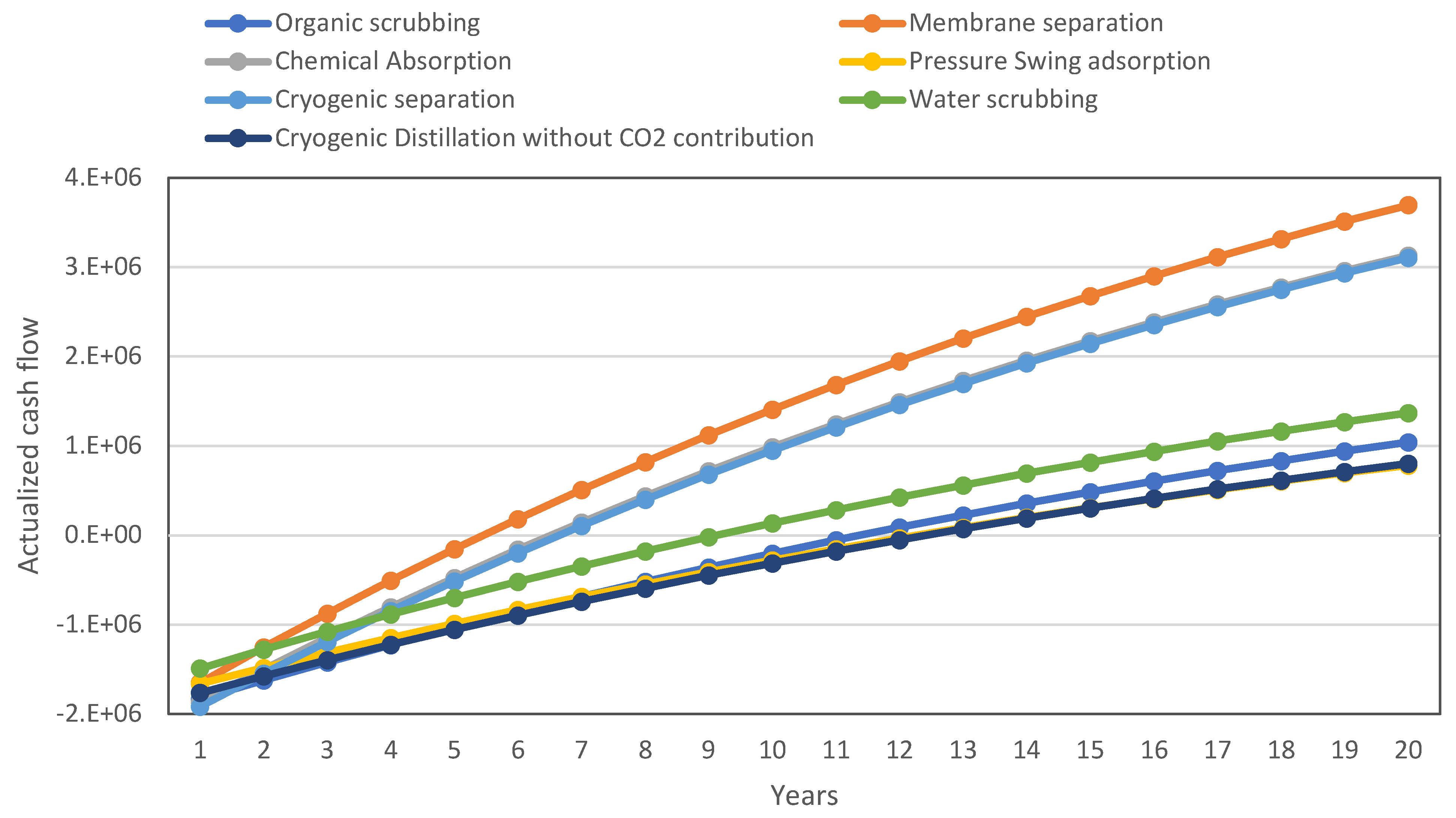
The evaluation is based on self-consumption logic, where electricity production is calculated from the biomethane produced, taking into account its calorific value and conversion efficiency. The economic assumptions in Table 12 are based on the Italian landscape, including the incentivized electricity pricing. The necessary consumption for upgrading is subtracted from this electricity production, and then the incentivized selling price of electricity is applied. The thermal consumption is converted in electrical consumption and counted in cost, presented in Table 13.
The results, shown in Figure 20, suggest that membrane separation, cryogenic distillation, and chemical absorption are the most economically viable methods for this facility when considering the sale of CO2. The primary advantage of membrane separation is its energy efficiency, which makes it a favorable solution. The economic feasibility of cryogenic distillation relies on the opportunity to sell liquid carbon dioxide. A second scenario without the revenue from selling CO2 is shown to prove this, providing unfavorable results. Additionally, this initial analysis does not consider that the product of cryogenic distillation is LBM, which is usually sold at a higher price compared to biomethane. The chemical absorption technique is convenient because of its low electrical consumption and minimal methane loss. The pretreatment is not being considered, but it can be a significant cost, especially for sensitive processes like cryogenic distillation.

5. Conclusions

Biogas, a renewable energy source, has shown promise in addressing environmental and energy challenges worldwide. Its use has been extending beyond heat and power generation in recent years. This research thoroughly examined advanced biogas upgrading methods and discussed the impact of oxygen and nitrogen in cryogenic distillation. An economic analysis of many biogas upgrading technologies demonstrates that membrane separation provides the most favorable outcomes based on the hypotheses. Choosing suitable technologies is influenced by aspects beyond only prices, including biogas quality, location, and technical specifications. Biological approaches in industrial-scale testing and optimization situations have great promise but are not widely researched. An expanding CO2 market can shift the balance in favor of technologies capable of efficiently capturing carbon dioxide in a suitable purity and state, such as cryogenic distillation.
Biogas, which is a renewable energy source, has the potential to address environmental and energy concerns all over the world. Over the last years, its applications have expanded beyond the combined heat and power generation, through the internal combustion engine, to the production of biomethane, thanks to the separation of the carbon dioxide. In this paper, advanced biogas upgrading techniques have been extensively investigated, comparing characteristics, main requirements, material, operating conditions, performance, and technology suppliers. The work even includes the state of the art of the biogas pretreatment step to clean the fuel before the upgrading system. In addition to the commercial upgrading technologies, biological solutions have been presented: although they have been tested at an industrial scale, they are not yet ready for the market but have a great potentiality in the near future. Moreover, a focus on an emerging technology, cryogenic distillation, has been made, looking at the impact of the oxygen and nitrogen content in the biogas stream on the process performance. In addition, a preliminary economic analysis has been proposed to compare the main upgrading technologies in the Italian context, showing that membrane separation provides the most favorable outcomes. However, it is worth mentioning that choosing suitable technologies is influenced by aspects beyond only prices, including biogas quality, location, and technical specifications. An increase in the valorization and expansion of the CO2 market in the near future can favor upgrading technologies, such as cryogenic distillation, that produce high quality CO2 at the liquid state as a subproduct, which is thus ready for storage and/or transportation, without the need of additional components.

Author Contributions

M.G. Conceptualization, simulation, and writing—original draft; G.D.M. Conceptualization and writing—review and editing. All authors have read and agreed to the published version of the manuscript.

Funding

This research was funded by the Italian Ministry for Education & Research (MIUR) via project Programma Operativo Nazionale (PON)—Azione IV.5 “Dottorati su tematiche green”—Ciclo XXXVII—code DOT1346224-7.

Conflicts of Interest

The authors declare no conflict of interest.

Nomenclature

AD anaerobic digestion
BF biofilters
BS bioscrubber
BTS biotrickling filters
CA chemical absorption
CA Cellulose Acetate
CD cryogenic distillation
CFZ controlled freezing zone
CHP cogenerative heat and power
DEA Diethanolamine
GHG greenhouse gas emission
GWP Global Warming Potential
HETP Height Equivalent to a Theoretical Plate
LBM liquefied biomethane
MEA Monoethanolamine
MOF Metal-organic frameworks
MS membrane separation
NFM N-Formylmorpholine
NH3 ammonia
NMP N-Methylpyrrolidone
OFMSW organic fraction of municipal solid waste
OS organic scrubbing
PC Polycarbonate
PI Polymide
PSA pressure swing adsorption
RTO regenerative thermal oxidizer
TSA temperature swing adsorption
VOCs volatile organic compounds
VSA vacuum swing adsorption
WS water scrubbing

References

  1. Renewable Capacity Statistics 2022. Available online: https://www.irena.org/publications/2022/Apr/Renewable-Capacity-Statistics-2022 (accessed on 10 April 2024).
  2. European Climate Law—European Commission. Available online: https://climate.ec.europa.eu/eu-action/european-climate-law_en (accessed on 28 March 2024).
  3. Achinas, S.; Willem Euverink, G.J. Rambling Facets of Manure-Based Biogas Production in Europe: A Briefing. Renew. Sustain. Energy Rev. 2020, 119, 109566. [Google Scholar] [CrossRef]
  4. Johansson, V.; Lehtveer, M.; Göransson, L. Biomass in the Electricity System: A Complement to Variable Renewables or a Source of Negative Emissions? Energy 2019, 168, 532–541. [Google Scholar] [CrossRef]
  5. Tshikovhi, A.; Motaung, T.E. Technologies and Innovations for Biomass Energy Production. Sustainability 2023, 15, 12121. [Google Scholar] [CrossRef]
  6. Zabed, H.; Sahu, J.N.; Boyce, A.N.; Faruq, G. Fuel Ethanol Production from Lignocellulosic Biomass: An Overview on Feedstocks and Technological Approaches. Renew. Sustain. Energy Rev. 2016, 66, 751–774. [Google Scholar] [CrossRef]
  7. Pham, T.P.T.; Kaushik, R.; Parshetti, G.K.; Mahmood, R.; Balasubramanian, R. Food Waste-to-Energy Conversion Technologies: Current Status and Future Directions. Waste Manag. 2015, 38, 399–408. [Google Scholar] [CrossRef] [PubMed]
  8. Advanced Thermochemical Conversion Technologies Used for Energy Generation: Advancement and Prospects—ScienceDirect. Available online: https://www.sciencedirect.com/science/article/pii/S0016236122009644?via%3Dihub (accessed on 10 April 2024).
  9. Microbial Conversion of Waste Biomass into Bioethanol: Current Challenges and Future Prospects|Biomass Conversion and Biorefinery. Available online: https://link.springer.com/article/10.1007/s13399-021-01824-z (accessed on 10 April 2024).
  10. Verbeeck, K.; Buelens, L.C.; Galvita, V.V.; Marin, G.B.; Geem, K.M.V.; Rabaey, K. Upgrading the Value of Anaerobic Digestion via Chemical Production from Grid Injected Biomethane. Energy Environ. Sci. 2018, 11, 1788–1802. [Google Scholar] [CrossRef]
  11. Náthia-Neves, G.; Berni, M.; Dragone, G.; Mussatto, S.I.; Forster-Carneiro, T. Anaerobic Digestion Process: Technological Aspects and Recent Developments. Int. J. Environ. Sci. Technol. 2018, 15, 2033–2046. [Google Scholar] [CrossRef]
  12. EBA Statistical Report 2023|European Biogas Association. Available online: https://www.europeanbiogas.eu/eba-statistical-report-2023/ (accessed on 6 March 2024).
  13. Florio, C.; Fiorentino, G.; Corcelli, F.; Ulgiati, S.; Dumontet, S.; Güsewell, J.; Eltrop, L. A Life Cycle Assessment of Biomethane Production from Waste Feedstock Through Different Upgrading Technologies. Energies 2019, 12, 718. [Google Scholar] [CrossRef]
  14. Marconi, P.; Rosa, L. Role of Biomethane to Offset Natural Gas. Renew. Sustain. Energy Rev. 2023, 187, 113697. [Google Scholar] [CrossRef]
  15. Directive (EU) 2018/2001 of the European Parliament and of the Council of 11 December 2018 on the Promotion of the Use of Energy from Renewable Sources (Recast) (Text with EEA Relevance). 2018, Volume 328. Available online: https://eur-lex.europa.eu/eli/dir/2018/2001/oj (accessed on 3 March 2024).
  16. Decreto Direttoriale n. 23 Del 13 Gennaio 2023 Di Approvazione Delle Regole Applicative Del Decreto Ministeriale n. 340 Del 15 Settembre 2022 Recante Disposizioni per l’incentivazione Del Biometano Immesso Nella Rete Del Gas Naturale | Ministero Dell’Ambiente e Della Sicurezza Energetica. Available online: https://www.mase.gov.it/bandi/decreto-direttoriale-n-23-del-13-gennaio-2023-di-approvazione-delle-regole-applicative-del (accessed on 10 April 2024).
  17. Das, J.; Ravishankar, H.; Lens, P.N.L. Biological Biogas Purification: Recent Developments, Challenges and Future Prospects. J. Environ. Manag. 2022, 304, 114198. [Google Scholar] [CrossRef]
  18. Syed, M.; Soreanu, G.; Falletta, P.; Béland, M. Removal of Hydrogen Sulfide from Gas Streams Using Biological Processes—A Review. Can. Biosyst. Eng./Le Genie Des Biosyst. Au Can. 2006, 48, 2.1–2.13. [Google Scholar]
  19. Sun, Z.; Pang, B.; Xi, J.; Hu, H.-Y. Screening and Characterization of Mixotrophic Sulfide Oxidizing Bacteria for Odorous Surface Water Bioremediation. Bioresour. Technol. 2019, 290, 121721. [Google Scholar] [CrossRef] [PubMed]
  20. Di Capua, F.; Pirozzi, F.; Lens, P.N.L.; Esposito, G. Electron Donors for Autotrophic Denitrification. Chem. Eng. J. 2019, 362, 922–937. [Google Scholar] [CrossRef]
  21. Das, J.; Rene, E.R.; Dupont, C.; Dufourny, A.; Blin, J.; van Hullebusch, E.D. Performance of a Compost and Biochar Packed Biofilter for Gas-Phase Hydrogen Sulfide Removal. Bioresour. Technol. 2019, 273, 581–591. [Google Scholar] [CrossRef]
  22. Kennes, C.; Veiga, M.C. Inert Filter Media for the Biofiltration of Waste Gases—Characteristics and Biomass Control. Rev. Environ. Sci. Biotechnol. 2002, 1, 201–214. [Google Scholar] [CrossRef]
  23. DMT Clear Gas Solutions: Biogas Upgrading to Renewable Natural Gas. Available online: https://www.dmt-cgs.com/ (accessed on 29 March 2024).
  24. Biogasclean | Biogas Cleaning, H2S Removal & Desulphurization. Available online: https://biogasclean.com/ (accessed on 29 March 2024).
  25. Le Borgne, S.; Baquerizo, G. Microbial Ecology of Biofiltration Units Used for the Desulfurization of Biogas. ChemEngineering 2019, 3, 72. [Google Scholar] [CrossRef]
  26. Ren, B.; Zhao, Y.; Lyczko, N.; Nzihou, A. Current Status and Outlook of Odor Removal Technologies in Wastewater Treatment Plant. Waste Biomass Valor 2019, 10, 1443–1458. [Google Scholar] [CrossRef]
  27. Technologies. Available online: https://www.veoliawatertechnologies.com/en/technologies-1 (accessed on 29 March 2024).
  28. Home—PAQUES. Available online: https://en.paques.nl/ (accessed on 29 March 2024).
  29. Wang, Y.; Chang, M.; Pan, Y.; Zhang, K.; Lyu, L.; Wang, M.; Zhu, T. Performance Analysis and Optimization of Ammonium Removal in a New Biological Folded Non-Aerated Filter Reactor. Sci. Total Environ. 2019, 688, 505–512. [Google Scholar] [CrossRef]
  30. Pal, P. Chapter 3—Biological Treatment Technology. In Industrial Water Treatment Process Technology; Pal, P., Ed.; Butterworth-Heinemann: Oxford, UK, 2017; pp. 65–144. ISBN 978-0-12-810391-3. [Google Scholar]
  31. Van der Heyden, C.; Volcke, E.I.P.; Brusselman, E.; Demeyer, P. Comparative 1-Year Performance Study of Two Full-Scale Biotrickling Filters for Ammonia Removal Including Nitrous Oxide Emission Monitoring. Biosyst. Eng. 2019, 188, 178–189. [Google Scholar] [CrossRef]
  32. U.S. Environmental Protection Agency. Technical Overview of Volatile Organic Compounds. Available online: https://www.epa.gov/indoor-air-quality-iaq/technical-overview-volatile-organic-compounds (accessed on 2 April 2024).
  33. Accettola, F.; Guebitz, G.M.; Schoeftner, R. Siloxane Removal from Biogas by Biofiltration: Biodegradation Studies. Clean Technol. Environ. Policy 2008, 10, 211–218. [Google Scholar] [CrossRef]
  34. Boada, E.; Santos-Clotas, E.; Bertran, S.; Cabrera-Codony, A.; Martín, M.J.; Bañeras, L.; Gich, F. Potential Use of Methylibium Sp. as a Biodegradation Tool in Organosilicon and Volatile Compounds Removal for Biogas Upgrading. Chemosphere 2020, 240, 124908. [Google Scholar] [CrossRef] [PubMed]
  35. Calbry-Muzyka, A.; Madi, H.; Rüsch-Pfund, F.; Gandiglio, M.; Biollaz, S. Biogas Composition from Agricultural Sources and Organic Fraction of Municipal Solid Waste. Renew. Energy 2022, 181, 1000–1007. [Google Scholar] [CrossRef]
  36. Paolini, V.; Petracchini, F.; Carnevale, M.; Gallucci, F.; Perilli, M.; Esposito, G.; Segreto, M.; Occulti, L.G.; Scaglione, D.; Ianniello, A.; et al. Characterisation and Cleaning of Biogas from Sewage Sludge for Biomethane Production. J. Environ. Manag. 2018, 217, 288–296. [Google Scholar] [CrossRef] [PubMed]
  37. Santos-Clotas, E.; Cabrera-Codony, A.; Boada, E.; Gich, F.; Muñoz, R.; Martín, M.J. Efficient Removal of Siloxanes and Volatile Organic Compounds from Sewage Biogas by an Anoxic Biotrickling Filter Supplemented with Activated Carbon. Bioresour. Technol. 2019, 294, 122136. [Google Scholar] [CrossRef] [PubMed]
  38. Wang, G.; Zhang, Z.; Hao, Z. Recent Advances in Technologies for the Removal of Volatile Methylsiloxanes: A Case in Biogas Purification Process. Crit. Rev. Environ. Sci. Technol. 2019, 49, 2257–2313. [Google Scholar] [CrossRef]
  39. Yang, L.; Corsolini, S.I. Online Removal of Volatile Siloxanes in Solid-State Anaerobic Digester Biogas Using a Biofilter and an Activated Carbon Filter. J. Environ. Chem. Eng. 2019, 7, 103284. [Google Scholar] [CrossRef]
  40. Desotec. Available online: https://www.desotec.com/it/ (accessed on 19 April 2024).
  41. Global Activated Carbon Producer NORIT—Purity for Life. Available online: https://norit.com (accessed on 19 April 2024).
  42. Ardolino, F.; Cardamone, G.F.; Parrillo, F.; Arena, U. Biogas-to-Biomethane Upgrading: A Comparative Review and Assessment in a Life Cycle Perspective. Renew. Sustain. Energy Rev. 2021, 139, 110588. [Google Scholar] [CrossRef]
  43. Incer-Valverde, J.; Korayem, A.; Tsatsaronis, G.; Morosuk, T. “Colors” of Hydrogen: Definitions and Carbon Intensity. Energy Convers. Manag. 2023, 291, 117294. [Google Scholar] [CrossRef]
  44. U.S. Environmental Protection Agency. Understanding Global Warming Potentials. Available online: https://www.epa.gov/ghgemissions/understanding-global-warming-potentials (accessed on 11 April 2024).
  45. Huonder, A.; Olsen, D. Methane Emission Reduction Technologies for Natural Gas Engines: A Review. Energies 2023, 16, 7054. [Google Scholar] [CrossRef]
  46. Angelidaki, I.; Xie, L.; Luo, G.; Zhang, Y.; Oechsner, H.; Lemmer, A.; Munoz, R.; Kougias, P.G. Chapter 33—Biogas Upgrading: Current and Emerging Technologies. In Biofuels: Alternative Feedstocks and Conversion Processes for the Production of Liquid and Gaseous Biofuels, 2nd ed.; Pandey, A., Larroche, C., Dussap, C.-G., Gnansounou, E., Khanal, S.K., Ricke, S., Eds.; Biomass, Biofuels, Biochemicals; Academic Press: Cambridge, MA, USA, 2019; pp. 817–843. ISBN 978-0-12-816856-1. [Google Scholar]
  47. IUPAC-NIST Solubilities Database. Available online: https://srdata.nist.gov/solubility/sol_detail.aspx?sysID=62_1 (accessed on 11 April 2024).
  48. Bauer, F.; Hulteberg, C.; Persson, T.; Tamm, D. Biogas Upgrading—Review of Commercial Technologies; Svenskt Gastekniskt Center AB: Malmö, Sweden, 2013. [Google Scholar]
  49. Struk, M.; Kushkevych, I.; Vítězová, M. Biogas Upgrading Methods: Recent Advancements and Emerging Technologies. Rev. Environ. Sci. Biotechnol. 2020, 19, 651–671. [Google Scholar] [CrossRef]
  50. Ahmed, S.F.; Mofijur, M.; Tarannum, K.; Chowdhury, A.T.; Rafa, N.; Nuzhat, S.; Kumar, P.S.; Vo, D.-V.N.; Lichtfouse, E.; Mahlia, T.M.I. Biogas Upgrading, Economy and Utilization: A Review. Environ. Chem. Lett. 2021, 19, 4137–4164. [Google Scholar] [CrossRef]
  51. Upadhyay, A.; Kovalev, A.A.; Zhuravleva, E.A.; Kovalev, D.A.; Litti, Y.V.; Masakapalli, S.K.; Pareek, N.; Vivekanand, V. Recent Development in Physical, Chemical, Biological and Hybrid Biogas Upgradation Techniques. Sustainbility 2023, 15, 476. [Google Scholar] [CrossRef]
  52. Firdaus, M.; Kolmetz, K.; Dwijayanti, A.; Hoon, C.Y. Distillation Column Selection, Sizing and Troubleshooting, Kolmetz Handbook of Process Equipment Design. 2013. Available online: https://www.researchgate.net/publication/336591526_Distillation_Column_Selection_Sizing_and_Troubleshooting_Kolmetz_Handbook_of_Process_Equipment_Design (accessed on 5 March 2024).
  53. Ryckebosch, E.; Drouillon, M.; Vervaeren, H. Techniques for Transformation of Biogas to Biomethane. Biomass Bioenergy 2011, 35, 1633–1645. [Google Scholar] [CrossRef]
  54. Aghel, B.; Behaein, S.; Wongwises, S.; Shadloo, M.S. A Review of Recent Progress in Biogas Upgrading: With Emphasis on Carbon Capture. Biomass Bioenergy 2022, 160, 106422. [Google Scholar] [CrossRef]
  55. Khan, M.U.; Lee, J.T.E.; Bashir, M.A.; Dissanayake, P.D.; Ok, Y.S.; Tong, Y.W.; Shariati, M.A.; Wu, S.; Ahring, B.K. Current Status of Biogas Upgrading for Direct Biomethane Use: A Review. Renew. Sustain. Energy Rev. 2021, 149, 111343. [Google Scholar] [CrossRef]
  56. Carranza-Abaid, A.; Wanderley, R.R.; Knuutila, H.K.; Jakobsen, J.P. Analysis and Selection of Optimal Solvent-Based Technologies for Biogas Upgrading. Fuel 2021, 303, 121327. [Google Scholar] [CrossRef]
  57. Sun, Q.; Li, H.; Yan, J.; Liu, L.; Yu, Z.; Yu, X. Selection of Appropriate Biogas Upgrading Technology—A Review of Biogas Cleaning, Upgrading and Utilisation. Renew. Sustain. Energy Rev. 2015, 51, 521–532. [Google Scholar] [CrossRef]
  58. Korson, L.; Drost-Hansen, W.; Millero, F.J. Viscosity of Water at Various Temperatures. J. Phys. Chem. 1969, 73, 34–39. [Google Scholar] [CrossRef]
  59. Xiang, H.W.; Laesecke, A.; Huber, M.L. A New Reference Correlation for the Viscosity of Methanol. J. Phys. Chem. Ref. Data 2006, 35, 1597–1620. [Google Scholar] [CrossRef]
  60. Langan, J.R.; Salmon, G.A. Physical Properties of N-Methylpyrrolidinone as Functions of Temperature. J. Chem. Eng. Data 1987, 32, 420–422. [Google Scholar] [CrossRef]
  61. Cavaignac, R.S.; Ferreira, N.L.; Guardani, R. Techno-Economic and Environmental Process Evaluation of Biogas Upgrading via Amine Scrubbing. Renew. Energy 2021, 171, 868–880. [Google Scholar] [CrossRef]
  62. Bishnoi, S.; Rochelle, G.T. Absorption of Carbon Dioxide into Aqueous Piperazine: Reaction Kinetics, Mass Transfer and Solubility. Chem. Eng. Sci. 2000, 55, 5531–5543. [Google Scholar] [CrossRef]
  63. Rufford, T.E.; Smart, S.; Watson, G.C.Y.; Graham, B.F.; Boxall, J.; Diniz da Costa, J.C.; May, E.F. The Removal of CO2 and N2 from Natural Gas: A Review of Conventional and Emerging Process Technologies. J. Pet. Sci. Eng. 2012, 94–95, 123–154. [Google Scholar] [CrossRef]
  64. Choi, W.-J.; Seo, J.-B.; Jang, S.-Y.; Jung, J.-H.; Oh, K.-J. Removal Characteristics of CO2 Using Aqueous MEA/AMP Solutions in the Absorption and Regeneration Process. J. Environ. Sci. 2009, 21, 907–913. [Google Scholar] [CrossRef]
  65. Method and Apparatus for Fractionating Gaseous Mixtures by Adsorption—EXXON RESEARCH ENGINEERING CO. Available online: https://www.freepatentsonline.com/2944627.html (accessed on 12 April 2024).
  66. Saha, D.; Bao, Z.; Jia, F.; Deng, S. Adsorption of CO2, CH4, N2O, and N2 on MOF-5, MOF-177, and Zeolite 5A. Environ. Sci. Technol. 2010, 44, 1820–1826. [Google Scholar] [CrossRef] [PubMed]
  67. Ritter, J.A.; Yang, R.T. Equilibrium Adsorption of Multicomponent Gas Mixtures at Elevated Pressures. Ind. Eng. Chem. Res. 1987, 26, 1679–1686. [Google Scholar] [CrossRef]
  68. Bao, Z.; Alnemrat, S.; Yu, L.; Vasiliev, I.; Ren, Q.; Lu, X.; Deng, S. Kinetic Separation of Carbon Dioxide and Methane on a Copper Metal–Organic Framework. J. Colloid Interface Sci. 2011, 357, 504–509. [Google Scholar] [CrossRef]
  69. Membrane Technology and Applications—Richard W. Baker—Google Libri. Available online: https://books.google.it/books?hl=it&lr=&id=EyXgEAAAQBAJ&oi=fnd&pg=PA525&ots=i4UnaEFoQT&sig=lQxVRVPJBFOQvutNTRL8wAVOtXA&redir_esc=y#v=onepage&q&f=false (accessed on 12 April 2024).
  70. Gabrielli, P.; Gazzani, M.; Mazzotti, M. On the Optimal Design of Membrane-Based Gas Separation Processes. J. Membr. Sci. 2017, 526, 118–130. [Google Scholar] [CrossRef]
  71. UBE CO2 Separator for Biogas Upgrading. Available online: https://ube.es/products/biogas-upgrading-biomethane-co2-separator/ (accessed on 12 April 2024).
  72. Basu, S.; Khan, A.L.; Cano-Odena, A.; Liu, C.; Vankelecom, I.F.J. Membrane-Based Technologies for Biogas Separations. Chem. Soc. Rev. 2010, 39, 750–768. [Google Scholar] [CrossRef]
  73. Pellegrini, L.A.; De Guido, G.; Langé, S. Biogas to Liquefied Biomethane via Cryogenic Upgrading Technologies. Renew. Energy 2018, 124, 75–83. [Google Scholar] [CrossRef]
  74. Northrop, P.S.; Valencia, J.A. The CFZ™ Process: A Cryogenic Method for Handling High-CO2 and H2S Gas Reserves and Facilitating Geosequestration of CO2 and Acid Gases. Energy Procedia 2009, 1, 171–177. [Google Scholar] [CrossRef]
  75. Parker, P.M.E.; Northrop, S.; Valencia, J.A.; Foglesong, R.E.; Duncan, W.T. CO2 Management at ExxonMobil’s LaBarge Field, Wyoming, USA. Energy Procedia 2011, 4, 5455–5470. [Google Scholar] [CrossRef]
  76. Lastari, F. Ryan-Holmes and Modified Ryan-Holmes Processes for LNG Production. Ph.D. Thesis, Curtin University, Perth, Australia, 2009. [Google Scholar]
  77. Baccanelli, M.; Langé, S.; Rocco, M.; Pellegrini, L.; Colombo, E. Low Temperature Techniques for Natural Gas Purification and LNG Production: An Energy and Exergy Analysis. Appl. Energy 2016, 180, 546–559. [Google Scholar] [CrossRef]
  78. Yousef, A.M.; El-Maghlany, W.M.; Eldrainy, Y.A.; Attia, A. Low-Temperature Distillation Process for CO2/CH4 Separation: A Study for Avoiding CO2 Freeze-Out. J. Heat Transf. 2018, 140, 042001. [Google Scholar] [CrossRef]
  79. Yousef, A.M.; Eldrainy, Y.A.; El-Maghlany, W.M.; Attia, A. Biogas Upgrading Process via Low-Temperature CO2 Liquefaction and Separation. J. Nat. Gas Sci. Eng. 2017, 45, 812–824. [Google Scholar] [CrossRef]
  80. Yousef, A.M.; El-Maghlany, W.M.; Eldrainy, Y.A.; Attia, A. New Approach for Biogas Purification Using Cryogenic Separation and Distillation Process for CO2 Capture. Energy 2018, 156, 328–351. [Google Scholar] [CrossRef]
  81. Yousef, A.M.; El-Maghlany, W.M.; Eldrainy, Y.A.; Attia, A. Upgrading Biogas to Biomethane and Liquid CO2: A Novel Cryogenic Process. Fuel 2019, 251, 611–628. [Google Scholar] [CrossRef]
  82. Live Carbon Prices Today, Carbon Price Charts • Carbon Credits. Carbon Credits. 2024. Available online: https://carboncredits.com/carbon-prices-today/ (accessed on 6 March 2024).
  83. Aspen HYSYS | Process Simulation Software | AspenTech. Available online: https://www.aspentech.com/en/products/engineering/aspen-hysys (accessed on 23 February 2024).
  84. Welcome to Python.Org. Available online: https://www.python.org/ (accessed on 23 February 2024).
  85. Smith, R.; Inomata, H.; Peters, C. Chapter 6—Equations of State and Formulations for Mixtures. In Supercritical Fluid Science and Technology; Smith, R., Inomata, H., Peters, C., Eds.; Introduction to Supercritical Fluids; Elsevier: Amsterdam, The Netherlands, 2013; Volume 4, pp. 333–480. [Google Scholar]
  86. Xie, L.; Xu, J.; Zhang, Y.; He, Y. Biogas Upgrading. In Advances in Bioenergy; Elsevier: Amsterdam, The Netherlands, 2020; Volume 5, pp. 309–344. ISBN 978-0-12-820744-4. [Google Scholar]
  87. Liu, C.; Xiao, J.; Li, H.; Chen, Q.; Sun, D.; Cheng, X.; Li, P.; Dang, Y.; Smith, J.A.; Holmes, D.E. High Efficiency In-Situ Biogas Upgrading in a Bioelectrochemical System with Low Energy Input. Water Res. 2021, 197, 117055. [Google Scholar] [CrossRef] [PubMed]
  88. Tabatabaei, M.; Aghbashlo, M.; Valijanian, E.; Kazemi Shariat Panahi, H.; Nizami, A.-S.; Ghanavati, H.; Sulaiman, A.; Mirmohamadsadeghi, S.; Karimi, K. A Comprehensive Review on Recent Biological Innovations to Improve Biogas Production, Part 2: Mainstream and Downstream Strategies. Renew. Energy 2020, 146, 1392–1407. [Google Scholar] [CrossRef]
  89. Fu, S.; Angelidaki, I.; Zhang, Y. In Situ Biogas Upgrading by CO2-to-CH4 Bioconversion. Trends Biotechnol. 2021, 39, 336–347. [Google Scholar] [CrossRef]
  90. McPhy: Clean Hydrogen Production and Distribution Equipment. Available online: https://mcphy.com/en/ (accessed on 17 April 2024).
  91. Chi siamo—H2 Energy Srl 2023. Available online: https://www.h2e.it/2023/ (accessed on 6 March 2024).
  92. Lai, C.-Y.; Zhou, L.; Yuan, Z.; Guo, J. Hydrogen-Driven Microbial Biogas Upgrading: Advances, Challenges and Solutions. Water Res. 2021, 197, 117120. [Google Scholar] [CrossRef] [PubMed]
  93. Bose, A.; O’Shea, R.; Lin, R.; Murphy, J.D. A Comparative Evaluation of Design Factors on Bubble Column Operation in Photosynthetic Biogas Upgrading. Biofuel Res. J. 2021, 8, 1351–1373. [Google Scholar] [CrossRef]
  94. Rodero, M.d.R.; Carvajal, A.; Castro, V.; Navia, D.; de Prada, C.; Lebrero, R.; Muñoz, R. Development of a Control Strategy to Cope with Biogas Flowrate Variations during Photosynthetic Biogas Upgrading. Biomass Bioenergy 2019, 131, 105414. [Google Scholar] [CrossRef]
  95. Sutherland, D.L.; Park, J.; Heubeck, S.; Ralph, P.J.; Craggs, R.J. Size Matters—Microalgae Production and Nutrient Removal in Wastewater Treatment High Rate Algal Ponds of Three Different Sizes. Algal Res. 2020, 45, 101734. [Google Scholar] [CrossRef]
  96. Meier, L.; Barros, P.; Torres, A.; Vilchez, C.; Jeison, D. Photosynthetic Biogas Upgrading Using Microalgae: Effect of Light/Dark Photoperiod. Renew. Energy 2017, 106, 17–23. [Google Scholar] [CrossRef]
  97. Kapoor, R.; Ghosh, P.; Kumar, M.; Vijay, V.K. Evaluation of Biogas Upgrading Technologies and Future Perspectives: A Review. Environ. Sci. Pollut. Res. 2019, 26, 11631–11661. [Google Scholar] [CrossRef] [PubMed]
  98. Bassani, I.; Kougias, P.G.; Angelidaki, I. In-Situ Biogas Upgrading in Thermophilic Granular UASB Reactor: Key Factors Affecting the Hydrogen Mass Transfer Rate. Bioresour. Technol. 2016, 221, 485–491. [Google Scholar] [CrossRef] [PubMed]
  99. Bassani, I.; Kougias, P.G.; Treu, L.; Porté, H.; Campanaro, S.; Angelidaki, I. Optimization of Hydrogen Dispersion in Thermophilic Up-Flow Reactors for Ex Situ Biogas Upgrading. Bioresour. Technol. 2017, 234, 310–319. [Google Scholar] [CrossRef] [PubMed]
  100. Rachbauer, L.; Voitl, G.; Bochmann, G.; Fuchs, W. Biological Biogas Upgrading Capacity of a Hydrogenotrophic Community in a Trickle-Bed Reactor. Appl. Energy 2016, 180, 483–490. [Google Scholar] [CrossRef]
  101. Song, C.; Fan, Z.; Li, R.; Liu, Q.; Kitamura, Y. Efficient Biogas Upgrading by a Novel Membrane-Cryogenic Hybrid Process: Experiment and Simulation Study. J. Membr. Sci. 2018, 565, 194–202. [Google Scholar] [CrossRef]
  102. Song, C.; Liu, Q.; Ji, N.; Deng, S.; Zhao, J.; Li, Y.; Song, Y.; Li, H. Alternative Pathways for Efficient CO2 Capture by Hybrid Processes—A Review. Renew. Sustain. Energy Rev. 2018, 82, 215–231. [Google Scholar] [CrossRef]
  103. Francisco López, A.; Lago Rodríguez, T.; Faraji Abdolmaleki, S.; Galera Martínez, M.; Bello Bugallo, P.M. From Biogas to Biomethane: An In-Depth Review of Upgrading Technologies That Enhance Sustainability and Reduce Greenhouse Gas Emissions. Appl. Sci. 2024, 14, 2342. [Google Scholar] [CrossRef]
  104. Sulewski, P.; Ignaciuk, W.; Szymańska, M.; Wąs, A. Development of the Biomethane Market in Europe. Energies 2023, 16, 2001. [Google Scholar] [CrossRef]
  105. EU Carbon Permits-Price-Chart-Historical Data-News. Available online: https://tradingeconomics.com/commodity/carbon (accessed on 15 April 2024).
  106. Ongis, M.; Di Marcoberardino, G.; Manzolini, G.; Gallucci, F.; Binotti, M. Membrane Reactors for Green Hydrogen Production from Biogas and Biomethane: A Techno-Economic Assessment. Int. J. Hydrogen Energy 2023, 48, 19580–19595. [Google Scholar] [CrossRef]
  107. Jarre, M.; Noussan, M.; Poggio, A. Operational Analysis of Natural Gas Combined Cycle CHP Plants: Energy Performance and Pollutant Emissions. Appl. Therm. Eng. 2016, 100, 304–314. [Google Scholar] [CrossRef]
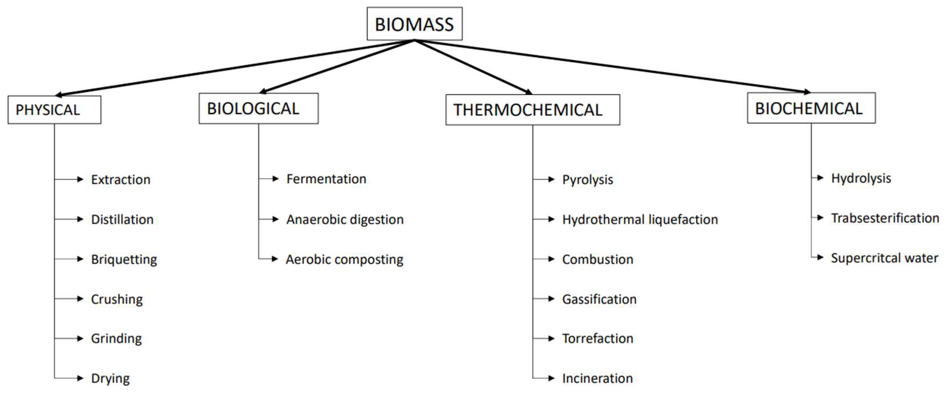
Figure 1. List of different biomass conversion methodologies.
Energies 17 02907 g001
Figure 2. Percentage of European biogas production per plant type in 2022.
Energies 17 02907 g002
Figure 3. Percentage upgrading technologies presence in Europe 2022.
Energies 17 02907 g003
Figure 4. Biogas and biomethane production in Europe through the years.
Energies 17 02907 g004
Figure 5. Bioscrubber representation.
Energies 17 02907 g005
Figure 6. Biogas upgrading technologies.
Energies 17 02907 g006
Figure 7. Water scrubbing with regeneration layout scheme.
Energies 17 02907 g007
Figure 8. Organic solvent biogas upgrading scheme layout.
Energies 17 02907 g008
Figure 9. Ammine scrubbing upgrading system plant layout.
Energies 17 02907 g009
Figure 10. (a) Skarstorm cycle representation; (b) representation of adsorbent property of two different materials.
Energies 17 02907 g010
Figure 11. Pressure swing adsorption upgrading system layout.
Energies 17 02907 g011
Figure 12. Biogas permeation through membranes module [61].
Energies 17 02907 g012
Figure 13. Membrane reactor layout: (a) two stage configuration; (b) three stage configuration.
Energies 17 02907 g013
Figure 14. Controlled freeze zone scheme layout.
Energies 17 02907 g014
Figure 15. Ryan–Holmes upgrading system scheme layout.
Energies 17 02907 g015
Figure 16. CO2/CH4 SLV equilibrium curve, image taken by ref. [71].
Energies 17 02907 g016
Figure 17. Cryogenic distillation one column layout scheme.
Energies 17 02907 g017
Figure 18. Distillate composition as function of biogas composition and condenser temperature.
Energies 17 02907 g018
Figure 19. Biological upgrading scheme: (a) in situ methanation; (b) ex situ methanation; (c) photosynthetic upgrading.
Energies 17 02907 g019
Figure 20. Upgrading technologies annualized cash flow.
Energies 17 02907 g020
Table 1. Different biogas composition based on the biomass type.
LandfilledAD from Agricultural AD from WasteNatural Gas
CH4 (v%)40–7049–6944–6785–92
CO2 (v%)25–4029–4430–440.2–1.5
N2 (v%)0–170.6–130.1–60.3
O2 (v%)0–30.2–30.1–3
Table 2. Categorization of the H2S removal based on bacteria family.
BacteriaFinal ProductReference
Cholorobium limicolaCH2O, H2O, SO42−[18]
Thiobacillus thioparusH+, SO42−, S0[19]
Thiobacillus denitrificansNH4+, H2O, S0[20]
Table 3. Solvent proprieties at different operating conditions.
TechnologySolventViscosity at Absorption Condition [mbarx s] × 10−8Viscosity at Desorption Condition [mbarx s] × 10−8
Water scrubbingWater1.31 (at 10 °C)0.5 (at 47 °C)[58]
Organic physical scrubbingMethanol3.25 (at 60 °C)0.8 (at 0 °C)[59]
NMP1.5 (at 15 °C)1.1 (at 54 °C)[60]
NFM17.1 (at −20 °C)8.3 (at 25 °C)[56]
Table 4. Amine characterization.
Amine TypeAbsorption
Capacity
[molCO2/molAmine]
AdvantagesDisadvantages
Monoethanolamine (MEA)0.45–0.52
  • High reactivity
  • Low solvent cost
  • Adequate thermal stability
  • High solvent losses
  • High regeneration energy
[63]
Diethanolamine (DEA)0.21–0.81
  • Low energy for regeneration
  • High solvent losses
  • High solvent degradation
[63]
N-methyldiethanolamine0.20–0.81
  • Low solvent degradation
  • Low absorption capacity
  • Relatively slow kinetics
[63]
2-Amino-2-methyl-1-propanol0.84
  • Slow degradation
  • High CO2 absorption capacity
  • Fast kinetics
  • Low absorption rate
[64]
Table 5. Adsorbent material characteristics.
Adsorbent MaterialTypeCO2/CH4 Equilibrium SelectivityCO2/CH4 Kinetic Selectivity
ZeoliteEquilibrium5.193.6[66]
Activated carbonEquilibrium3.29 [67]
Metal-organic frameworks (Cu-MOF)Kinetic1.869.7[68]
Table 6. Membrane selectivity based on material.
MaterialCO2/CH4 SelectivityCO2 Permeability
[10−10 cm3(STP) · cm/cm2 · s · cmHg]
Cellulose Acetate (CA)3010[69,72]
Polycarbonate (PC)32.5 [72]
Polymide (PI)42.813[69,72]
Table 7. Range limits of variables utilized in the Aspen Hysys model.
Min ValueMax Value
Condenser temperature [°C]−80−50
Reflux ratio1.43
Column pressure [bar]50507050
Number of column theoretical plate1125
Table 8. Composition of biogas utilized in the distillation column simulation.
CH4 [%]CO2 [%]N2 [%]O2 [%]
Composition 1603622
Composition 2504622
Composition 3504352
Composition 4504325
Table 9. Pearson correlation factor results.
Condenser
Temperature
PressureNumber of StageReflux RatioCH4 in
Biogas
CH4 in distillate −0.98<10−5<10−5<10−50.18
Distillate molar flow0.39<10−5<10−5<10−50.92
Table 10. Summary of the characteristics of several upgrade systems and a list of manufacturers.
WSOSCAPSAMSCD
CH4 purity95–9897–9996–99.595–9995–9997–99.9
Chemical dangersNoYesYesNoNoNo
Water pretretmentNoYesNoYesNoYes
Cleaning pretratmentNoYesYesYesYesYes
Offgas treatmentYesYesYesYesYesNo
Operational pressure4–104–81–24–106–1250–80
Output pressure4–102–71–22–46–8Depend on the final product
Thermal energy requirmentNoYesYesYes/NoNoYes
water useYesNoNoNoNoNo
ProducersMalmberg
Greenlane
HAASE Umwelttechnik GmbHHera CleantechMahler
Energietechnik
Air Liquide
AB Holding S.p.A
Prodeval
GtS Future Energy
Table 11. Biological upgrading conditions.
TypeTemperature [°C]Retentation TimeCH4 Purity [%]
In situ3820 days96[97]
In situ555–20 days82[98]
Ex situ554–15 h89.5–96.3[99]
Ex situ373.5 h96[100]
Table 12. Economic evaluation assumption.
Biogas production [Nm3/h]1000
Biogas composition [%mol CH4/CO2]60/40
Equivalent hour [h/y]8000
OPEX/CAPEX5%
Incentivized electricity price [€/MWh]124[17]
Carbon dioxide price [€/ton]30[105]
Biogas production cost [€/Nm3]0.2712[106]
Conversion efficiency50%[107]
Biomethane PCI [kWh/Nm3]10
Table 13. Upgrading technology operation and economic data [41,46,48,49,50,51].
OSMSCAPSACSWS
Methane loss [%]110.130.52
CAPEX [€/Nm3]204820612252184423001707
Electrical Consumption [kWh/Nm3]0.500.310.350.450.510.45
Disclaimer/Publisher’s Note: The statements, opinions and data contained in all publications are solely those of the individual author(s) and contributor(s) and not of MDPI and/or the editor(s). MDPI and/or the editor(s) disclaim responsibility for any injury to people or property resulting from any ideas, methods, instructions or products referred to in the content.