1. Introduction
1.1. Problem Description
Switching devices actuated by means of electromagnetic drives are very popular and widely used as active elements in LV power networks. Electromagnetically actuated switches in the form of EM power contactors or relays play important roles in the delivery and distribution of electric energy. In spite of the rapid development of semiconductive switching elements, electromagnetic-driven switches are commonly utilized due to their relatively simple architecture, high reliability, and simplicity of control. Because of the specific form of their driving element, they can be easily controlled using various types of microprocessor controllers [
1,
2]. Depending on the type of voltage they are designed for and the applied control method, driving electromagnets can be energized from an alternating current (AC) or direct current (DC) power source.
In the case of additional control circuit usage, the supply source problem of ensuring appropriate power supply conditions lies within the applied controller [
2,
3,
4,
5,
6], while in the case of a driving mechanism energized directly from the power network, there appears to be the problem of potential voltage sags, voltage surges, or supply source distortion occurrences. This method of control is, however, the most frequently used; therefore, the problem of electric energy quality plays a special role in this case.
While voltage surges in the LV power network seem to not pose a critical threat for drive electromagnets due to the high inductance of the coil (which holds the inate ability of surge wave suppression), voltage sags and sinusoidal waveform distortion can deteriorate operating conditions and may lead to unpredictable operation [
7,
8,
9,
10].
Finding and selecting the most appropriate solution to the above problem is problematic due to the small number of studies conducted on this topic over the last few years. This scarcity is most notable with regard to the number of published articles containing a detailed analysis of the impact of a harmonically polluted voltage source on the parameters of the relay switching process. Such a situation makes it difficult to conduct a broad analysis of the presented problem, to select and apply the appropriate measurement method, and thus to verify the previously stated theses. As a result, assessing the risk posed by higher harmonics in LV networks on LV relay operation is difficult.
The described phenomenon seems to be omitted or downplayed in analyzes of the LV relay operation. If such analyzes have been attempted, they have involved dedicated solid-state protective relays [
9,
10] or relatively large EM devices, such as electromagnetic contactors [
11,
12]. In sporadic cases, limited simulation analyses of the operation of switches were performed [
13]. This may be due to the problematic design of the measurement stand that would have to be built to analyze the operation of the relays. The reason may also be the relatively low power of switching devices and the low power of external circuits controlled through the relays. Therefore, it is assumed that potential problems related to ensuring the proper operation of LV relays do not pose a significant threat to the controlled circuits.
The research on the switching dynamics parameters of EM switches presented in the existing, sparse literature usually does not take into account the growing problem of harmonic pollution occurrence in the LV power network. Interestingly, this problem was discussed many years ago, albeit in very general terms and in a manner focused mainly on the operating parameters of EM power contactors. The presented case study is an attempt to return to considerations on the impact of higher harmonics on the operation of low-power electromagnetic relays controlled by direct connection to the LV power grid.
The negative impact of power network harmonic pollution on the operation and reliability of connected devices has been demonstrated many times in the existing literature [
7]. The low quality of commonly used domestic electronic devices and power electronic components, however, engenders voltage and current harmonic distortions [
14,
15]. These lead to the deterioration of the quality of electric energy delivered to consumers. Parameters determining the quality of electricity are included in dedicated standards, and, in accordance with these, the maximum share of odd harmonics should not exceed 2% [
16]. The presence in the power grid of harmonic pollution levels higher than those mentioned in the above standards brings about additional loss generation [
17,
18,
19], improper operation, premature aging, and device durability reduction. It is especially dangerous for various types of protective devices actuated by means of EM drives [
19,
20]. This fact forces the use of additional preventive methods in the form of various types of filtering systems and correction algorithms [
21].
The presented case study deals with the estimation of the supply voltage distortion level impact on LV relays equipped with AC electromagnetic drive operation, which are controlled directly from the power network. In the frame of the performed research, dynamic parameters at switching-on were measured for various supplying voltage distortion types and levels. In particular, the scope of the research included:
Relays time-related parameter determination;
Examination of the influence of the various voltage harmonic contents (THDu) and levels on drive electromagnet power supply conditions, e.g., voltage RMS value (URMS);
Potential risk of malfunctioning estimation with respect to appropriate implementation of the switching-on process;
Estimation of the impact of distorted voltage waveform switching-on applied phase (φ) on relay dynamic parameters;
Contacts bouncing phenomenon observation and, consequently, contacts bouncing time duration registering and number of contact bounces.
The article is divided into five sections.
The
Section 1 comprises a description of the problem discussed in the article and a short theoretical analysis of the switching-on process of circuit interrupters equipped with an EM drive. The problem of ensuring the necessary conditions for the correct implementation of the relay switching process was also discussed. The
Section 2, “Measurement Stand”, comprises a description of the measurement stand used and the essential characteristics of the research objects. The
Section 3, “Testing Method”, comprises a description of the measurement procedure used, along with sample charts of the measured values. The
Section 4, “Measurement Results”, covers the results of the obtained measurements, along with their analysis. The
Section 5 is a summary of the measurements performed and an attempt to answer questions arising after the experiments.
1.2. Theoretical Introduction
The AC1–AC8 operating categories define EM power contactors and relay functions [
22]. AC1–AC3 are the most frequently utilized operating categories dedicated to circuits comprised of resistive or a combination of resistive and inductive elements. This is related, among other issues, to the durability of the circuit breaker contact system when exposed to unfavorable operating conditions during switching operation.
Incorrect implementation of the switching-on process may lead to a variety of surge types, e.g., high-energy arc ignitions, overvoltages, or current surges. This may be a source of contact degradation and, in extreme cases, may lead to contact welding. The contact-making process, especially for switching devices operating at high frequency rates, determines relay reliability and durability.
For an appropriate and reliable realization of switching-on operation, a few essential conditions must be secured:
Providing sufficient energy to the driving coil in a sufficiently short period to counteract moving armature inertial forces;
Providing high enough energy volume during switching-on processes and, consequently, high enough voltage and current RMS values for a sufficiently long time period to counteract movable resistive forces;
Minimizing the contact bouncing effect during switching-on by means of the implementation of return springs and contact pressure springs with appropriate spring resilience;
Securing a high enough value of magnetic flux generated in the shading ring to prevent steady-state moving armature vibration;
Securing a high enough value of contact elasticity and contact pressure forces to prevent the contact bouncing effect;
Utilizing high-durability materials for contact design to prevent contact degradation.
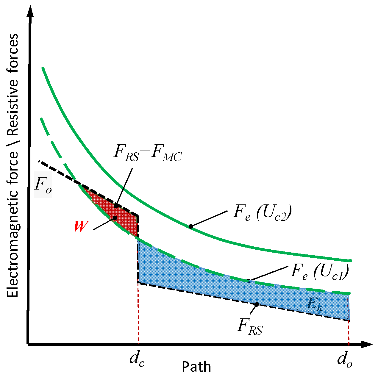
During normal operation, reliable switching-on process realization for devices equipped with electromagnetic driving mechanisms can be secured by means of ensuring an appropriate balance between driving forces (Fe) and resistive forces (Fo), according to (1). The resultant volume of driving force must overcome inertial forces, which are a function of armature mass (m) and resistance forces, which are dependent on movement resistance (b) and spring action (k). High movable armature mass may increase movement delay time (To) after supply voltage delivery. In turn, high movement resistance may be a source of movement time (Tm) elongation.
Moreover, the volume of magnetic flux responsible for driving force generation that is the result of current flowing through the coil depends on circuit parameters (magnetic material parameters, coil number of turns, and its resistance and inductance) and applied voltage (
Us), according to (2). Simultaneously, the provision of a suitable volume of magnetic flux generated by the shading ring and responsible for steady-state operation depends on ring parameters (
Rs) and ring coil currents (
is,
ic) (3). Finally, the volume of kinetic energy generated during the start-up depends on the achieved velocity of the moving armature (
v), coil inrush current, and the mechanical parameters of the relay structure (4).
wherein:
m—movable armature (movable core and contact system) mass;
b—friction coefficient between relay movable and stationary core components;
k—return and contact pressure spring resilience;
x—armature movement path;
ic—driving coil current;
is—shading ring current;
Rc—EM drive coil winding resistance;
Rs—shading ring resistance;
Fo(
x)—resistive force as a function of the armature displacement;
Uc(
t)—coil supply voltage;
Ψc(
is,
is,
x)—coil magnetic flux penetrating the core and shading ring;
Ψs(
is,
is,
x)—shading ring magnetic flux penetrating the ring and main core;
Fe(
ic,
is,
x)—electromagnetic driving force;
M(
x)—self and mutual inductance of the shading ring and driving coil;
v—reached velocity of moving armature.
The mutual positioning of the driving forces and resistive forces for relays equipped with a single set of contacts is displayed in
Figure 1.
To ensure proper operation of the drive, the electromagnet-generated EM force (
Fe) value must be higher than the existing sum of resistive forces (
Fo). In this connection, the coil responsible for this force generation must be powered by a suitable RMS value of supply voltage—
Uc2 in
Figure 1. Applying a lower voltage value—
Uc1—at the coil terminals may cause a loss of contact (
loc) phenomenon during starting-up or make it completely impossible to close the relay’s contacts. Possible voltage harmonic component presence (thus, possible distortion of the voltage waveform) may affect the resultant voltage RMS value.
2. Measurement Stand
2.1. Objects under Research
As mentioned in the introduction section, EM-actuated current interrupters are popular switching apparatuses commonly used for electric energy delivery and distribution, as well as for controlling other electrical devices. The subjects of the research were single-break LV EM relays supplied directly from the AC power network. Relays from different manufacturers, but with similar electrical and mechanical parameters, were used for the tests. The examined objects were adapted to operate at different rated current values (IN) flowing through the load circuit and thus through the relays’ contacts. Each relay was equipped with a set of normally opened and normally closed contacts combined with the same drive unit. All of the relays’ drive coils were designed to be powered by the same rated voltage (Uc). Apart from the above, all tested objects had similar movable part sizes, and, consequently, the masses of the moving armatures were characterized by similar values. Recorded differences in mass of the moving armature did not exceed c.a. 5%.
This method of selecting relays for research allowed the elimination of some experimental variables (e.g., inertial force impact) and allowed the focus to be placed solely on the influence of the electricity quality on device operation. Seven relay models and six parts of each model were examined in the frame of the experiment. The adopted procedure allowed for the elimination of the influence of the dispersion of parameters of individual relay elements that can come about during manufacturing processes. The basic parameters of the relays are collected in
Table 1.
2.2. Measurement Stand Description
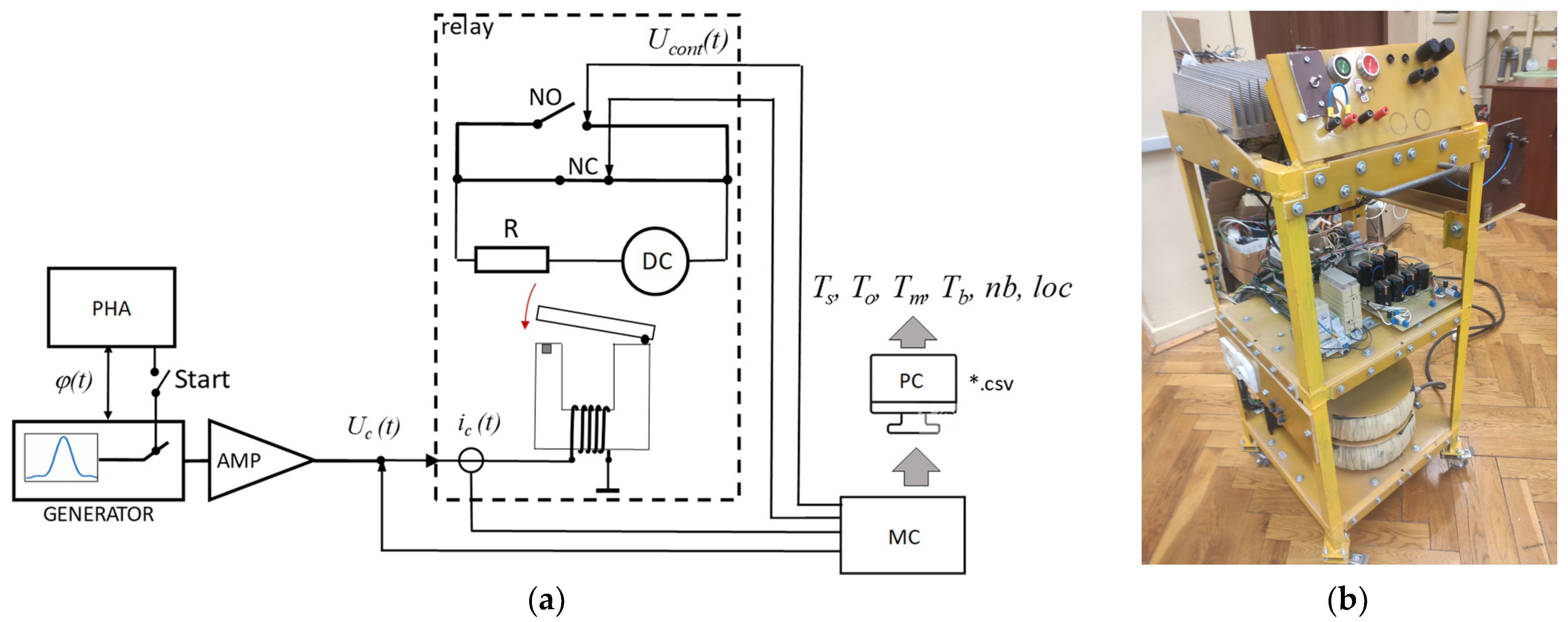
As part of the experimental work, a dedicated test stand was built, the diagram of which is presented in
Figure 2. The stand was comprised of the following elements:
Arbitrary generator (GENERATOR);
Phase adjuster (PHA);
High-power, single-channel, wide-band amplifier (AMP);
Tested relay(s) (RELAY);
Contact inspection circuit comprised of a DC voltage source and a resistor R;
Measuring card (MC);
PC with analytic software.
In order to obtain input data for the generator, internally developed software in the form of a Matlab script was used. Input data defining particular waveforms had the form of *.csv text files. According to the theory of Fourier analysis, the resulting signal waveform is a combination of individual sinusoidal harmonic components. The developed script for producing the final voltage waveform was based on introduced data describing the parameters of individual harmonic components (level, phase). At the same time, according to definition (5), the value of the resultant voltage waveform
THDu parameter value was calculated, describing the harmonic content level.
wherein:
U1—voltage fundamental oscillation;
Un—n-number of harmonic voltage RMS value.
In accordance with the initial assumption, the electromagnet coil is energized directly from the power network. To reflect the stochastic nature of the coil energizing procedure, supplying voltages were delivered to drive electromagnet coils at a variety of phases with a step of 20°, starting from 0°. For switching-on phase selection, a phase adjuster (PHA) developed for experiment needs was used.
Initially, the power of the voltage signals obtained at the output of the generator was too low to energize the drive coils. It was therefore necessary to amplify the signals to a level that ensured proper operation of the relay drive. This was realized by means of a specially developed single-channel amplifier (AMP). The amplifier was built in accordance with class A operation and was characterized by a 1.5 kVA maximum output power and a wide frequency (20 Hz–20 kHz) bandwidth. In addition, the maximum RMS voltage value for the sinusoidal signal obtained at the output was 100 V. Moreover, the measured maximum nonlinear distortion level for the developed amplifier design was lower than 1%. This allowed for the generation of an output voltage signal with the minimum distortion level in comparison to the signal obtained at the generator’s terminals.
For contact behavior inspection, a simple circuit was utilized consisting of a DC voltage source and a resistor connected in series to each set of contacts. By registering a voltage drop at the measurement resistance, thereby the voltage drop across the relay’s contacts, the determination of breaking of NC contacts and NO contacts creation moments was feasible. All recorded voltages and current signals were delivered to the measuring card through appropriate probes.
Measurement results obtained in the form of timing diagrams were, at the next stage, analyzed in terms of basic switching-on dynamic parameters. These included:
Armature movement delay time (To);
Armature movement time (Tm);
Total switching time (Ts);
Contacts bouncing time duration (Tb) determined for various supply voltage conditions (URMS, THDu, φ);
Number of contact bounces (nb);
Loss of contact phenomenon occurrence (loc).
The mentioned quantities were selected for analysis because they are the fundamental parameters determining the operation of the switching device. They define all stages of the switching process realized by every switching apparatus. To time duration determines the response time of the device to the applied control impulse. To combined with the armature movement time Tm, determines the speed at which the switching process is realized. Typically, the switching time Ts is specified in the manufacturer datasheet. However, the values provided by the manufacturer indicate the average time and do not take into account the randomness of the switching operation in the selected voltage phase. They assume a sinusoidal voltage wave and do not allow us to precisely determine which of the parameters (To or Tm) influences the change in the total switching time.
Finally, contact bounce time duration and the number of contact bounces define the reliability of the switching operation. In the long term, this phenomenon affects the durability of the contacts and the entire device and is defined as the “remaining lifetime” index. However, the loss of contacts phenomenon describes the correctness of the entire switching-on process. For research purposes, internally developed analytical software was used.
Parameters describing the switching-on process were ascertained based on the signals obtained from the measuring card and the numbers of individual samples, as well as the moments at which the supply voltage was applied, the NC contacts were opened, the NO contacts were closed, and the contact bounce phenomenon disappeared.
3. Testing Method
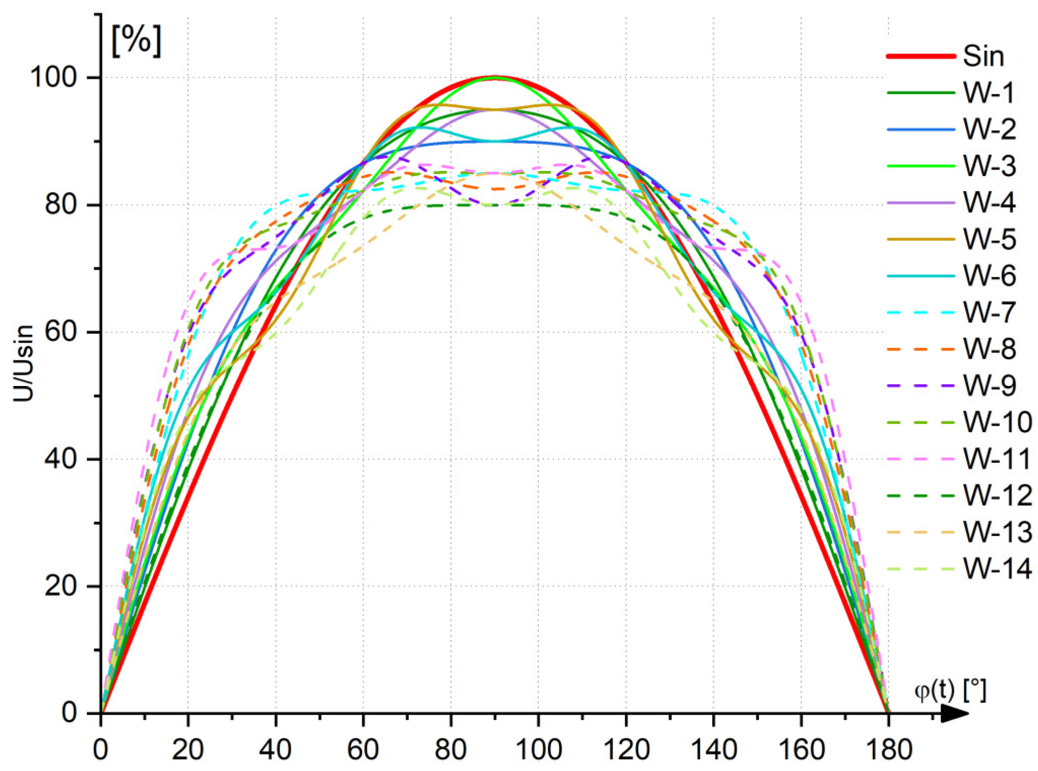
Figure 3 presents fourteen (W-1–W-14) voltage waveforms utilized for drive electromagnet energization. As a reference, a sine wave of voltage (Sin) was used, in which the RMS value at the amplifier terminals was set at 12 V. According to the utilized datasheets, this was the rated voltage of all the examined relays (assuming sinusoidal supply voltage delivery). For resultant distorted waveform generation, different levels of particular harmonic components were assumed at a “0” [rad] phase. During preliminary tests, we found that the adoption of a phase other than “0” [rad] resulted in the generation of voltage waveforms that did not occur in the low-voltage power grid or that occurred incidentally.
Bearing in mind that it is not possible to examine all potential combinations of harmonic components during a single experiment, the aim of the experiment was to indicate the impact of the common types of voltage distortions occurring in low-voltage networks on the operation of electromagnetic relays. For the experiments, waveforms comprised of the four most significant harmonic components were selected. The criterion for selecting the shape of the voltage signal was the overall frequency and level of individual voltage harmonics in the low-voltage power network.
Table 2 includes the parameters of the harmonic components forming the resulting voltage waveform. Accordingly, each waveform consisted of a composition of different levels of 1-st, 3-th, 5-th, and 7-th harmonic content. The remaining harmonics that may occur in an LV power network usually have values too low to be considered crucial for the dynamics of the relay’s operation at the switching-on stage. For verification purposes, some of the selected waveforms were defined by the same voltage
THDu factor value but characterized by different shapes.
According to the initial assumption, during standard operation and under normal operating conditions, the moment of switching-on the supply voltage is not controlled and may be realized at different voltage phases. Due to the specificity of the tested object, this is not a problem for an LV power grid because the power of the connected devices is negligible. In this connection, the problem of generating high energy disturbances, e.g., in the form of high values of in-rush currents, does not exist, nor does it cause additional distortions of the voltage wave.
To reflect the stochastic nature of the supply voltage delivery in the course of the experiment, a switching-on phase adjuster (PHA) was used. The developed controller, based on an introduced switch-on delay time (180° = 10 ms) in relation to the beginning of the generated wave, allowed the voltage to be applied in a specific phase. The resolution of the switching moment selection was c.a. 0.2 ms.
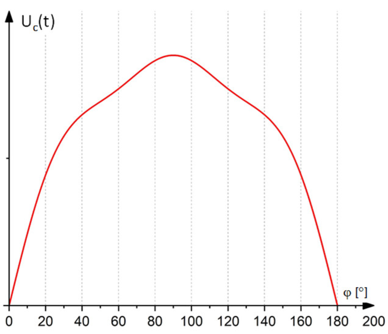
Figure 4 presents the half-period of the exemplary voltage waveform, along with the selected switching-on phases.
The tests assumed a 20° resolution of the voltage switching-on phase (S1–S9), beginning from 0° of the voltage half-wave (
Figure 4). Voltage and current diagrams of the electromagnet coil were recorded for each of the applied voltage phases. At the same time, the voltage across the relay’s contacts was registered. In order to eliminate accidental measurement discrepancies, each measurement was repeated 10 times. For each measurement, time-related dynamic parameters (
To,
Tm,
Ts, and
Tb) were then calculated, and the number of contacts bounced (
nb) was determined. Finally, the average values of the obtained results were calculated.
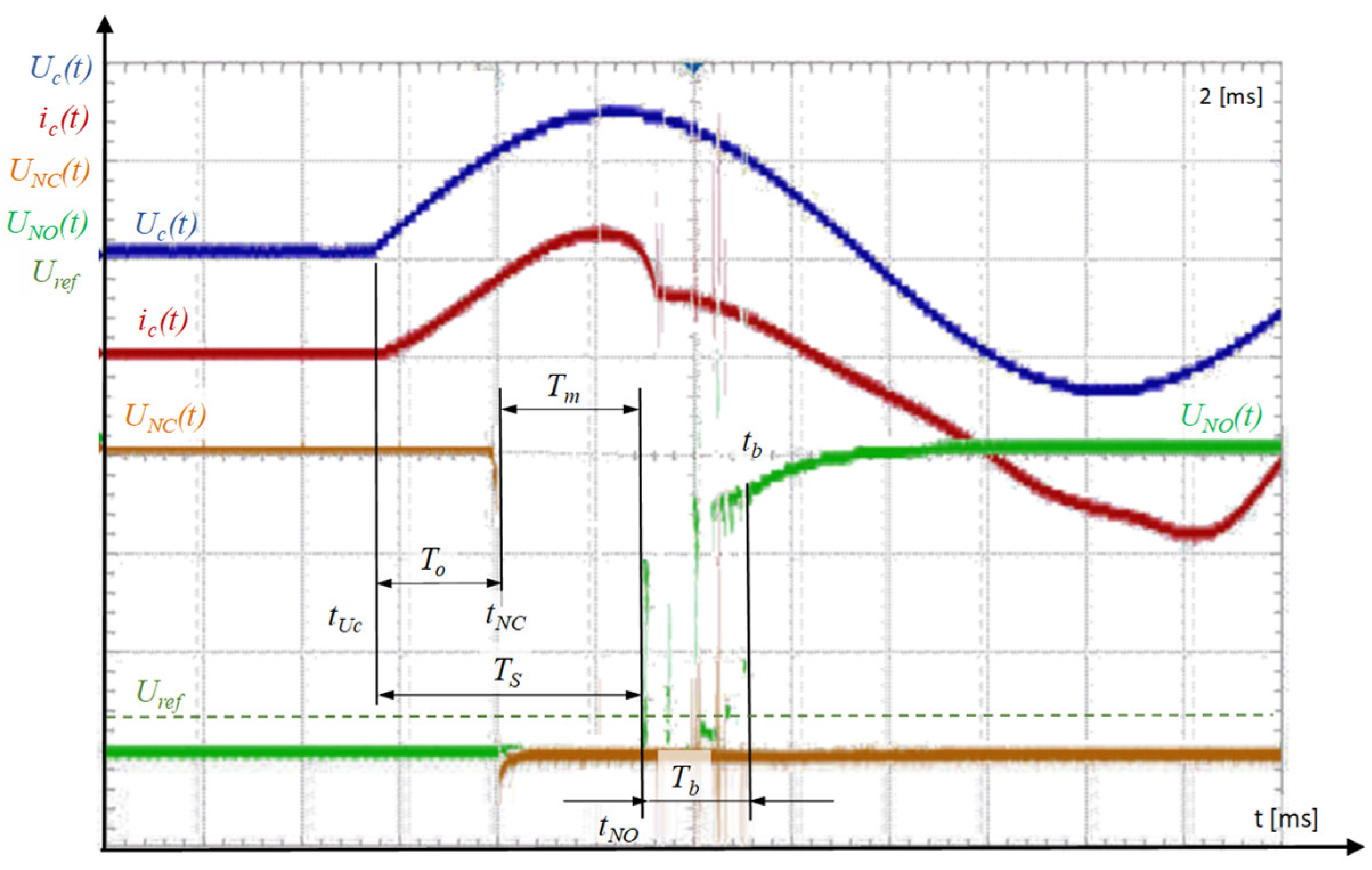
Exemplary diagrams of the recorded quantities for the 0° voltage phase with marked characteristic parameters of the switching-on procedure are presented in
Figure 5.
The time duration between the moment of the supply voltage delivery moment (
tUc) and the moment of opening the NC contacts (
tNC) is the armature movement delay time (
To) acc. to (6). In addition, the time between the NC contacts opening moment and the NO contacts making moment (
tNO) is the armature movement time duration (
Tm) and completion of the switching-on process acc. to (7). Furthermore, the sum of the movement delay time duration and the armature movement time duration is the total switching time (
Ts) acc. to (8).
During the switching-on of all electromechanical switching devices containing a set of mechanical contacts (usually three pairs of contacts), the contact bounce phenomenon is observed. According to theory, the number of contact bounces depends on, e.g.:
Velocity achieved by the moving unit,
Mass of the moving armature coupled with contacts;
The material the contacts are made of;
Contact spring pressure force;
Currents are currently flowing through the contacts, etc.
The contact-bouncing effect may cause overvoltages and contact-intensive wear due to electric arc burning. Contact bouncing time was marked in
Figure 5 as
Tb time.
Tb time was recognized as the time between the NO contacts making moment (
tNO), and
tb moment was recognized as the moment with no bouncing effect observed during an assumed time duration. The observation time can be adjusted, and during these experiments, this time interval was assumed to be 0.5 ms.
The number of contacts bounced (
nb) was determined as the detected number of voltage levels (
n) higher than the assumed reference voltage (
Uref), according to (9). The reference voltage level was ascertained experimentally and was set at 10% of the assumed test voltage. Too high a level of the adopted reference voltage resulted in too many inaccuracies in measurements and an underestimation of the number of bounces. In turn, assuming too low a reference voltage level resulted in an overestimation of the number of recorded bounces in relation to the number of bounces observed for the rated contact current.
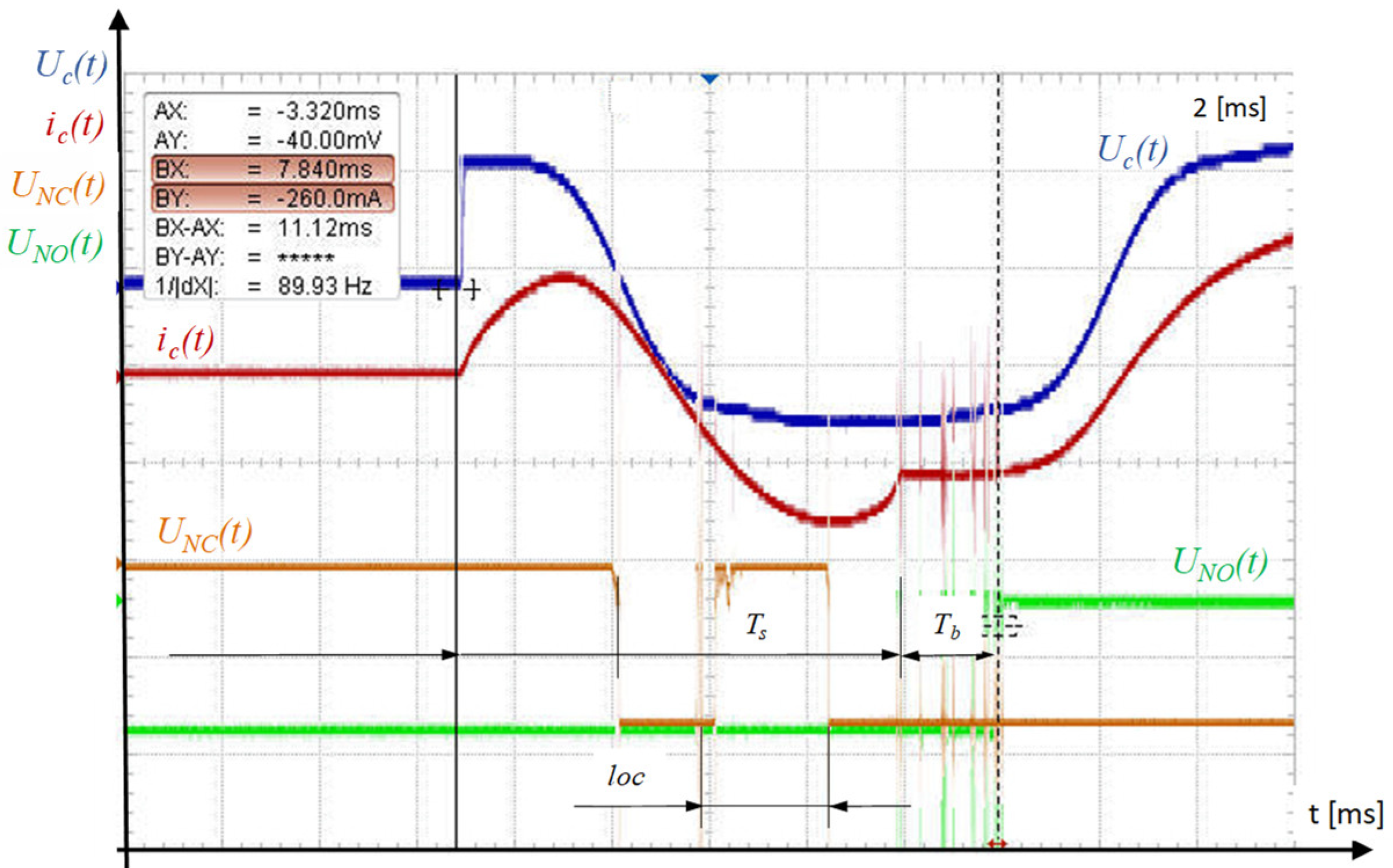
If the level of supplying voltage of the electromagnet coil is too low to generate, in the initial stage of the movable armature movement, an EM force at a level sufficient to overcome the resistance forces of the structure, loss of contacts may occur during the switching-on process. The same phenomenon may also occur in the case of a strongly distorted voltage sine wave that does not guarantee the generation of sufficient EM force in the initial stage of movement.
Figure 6 shows an example of the effects of powering the drive coil with a voltage with a strongly deformed voltage signal.
In this case, the loss of contact occurred for the 80° degree phase when the total RMS value of the voltage was too low to meet condition (10):
wherein:
x—armature displacement;
Fe(
ic,
is,
x)—electromagnetic driving force;
ic—driving coil current;
is—shading ring current;
Fo(
x)—total resistive force.
4. Measurement Results
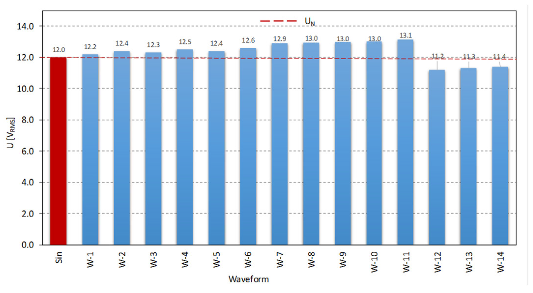
As a result of the tests, parameters responsible for the dynamics of relay armature movement were determined. The dependence of these parameters on the shape of the applied voltage waveform was also assessed. Each applied waveform was inspected in view of the RMS voltage value. Thus, the influence of the parameters of individual harmonics on the RMS value of the applied voltage was examined.
Figure 7 shows the RMS values of the examined voltage waveforms in comparison to their sine waves (Sin). The presence of harmonic content in the applied waveforms induced a change in the RMS values by up to about 10%. This fact affected the particular relay’s time-related parameters, which, in turn, were the result of the value and nature of changes in the generated electromagnetic forces (
Fe).
This is related to the amount of energy supplied to the drive coil during the switching process. The amount of energy supplied during the initial phase of armature movement is responsible for the time of standstill of the moving armature after the voltage pulse is applied. In turn, the total amount of energy supplied to the drive coil is responsible for the speed that the moving element achieves during its movement.
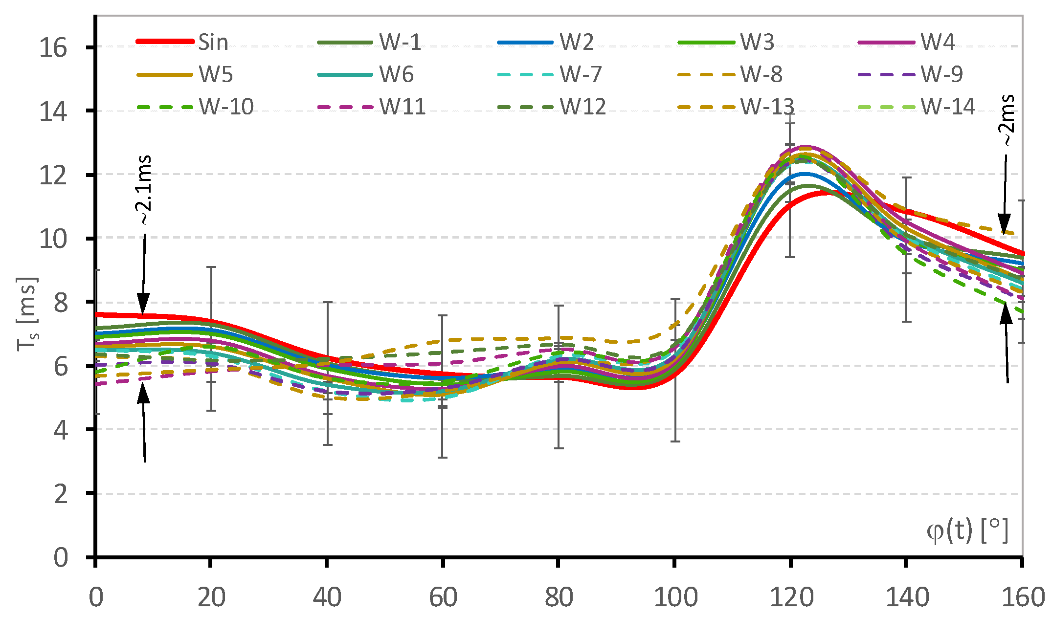
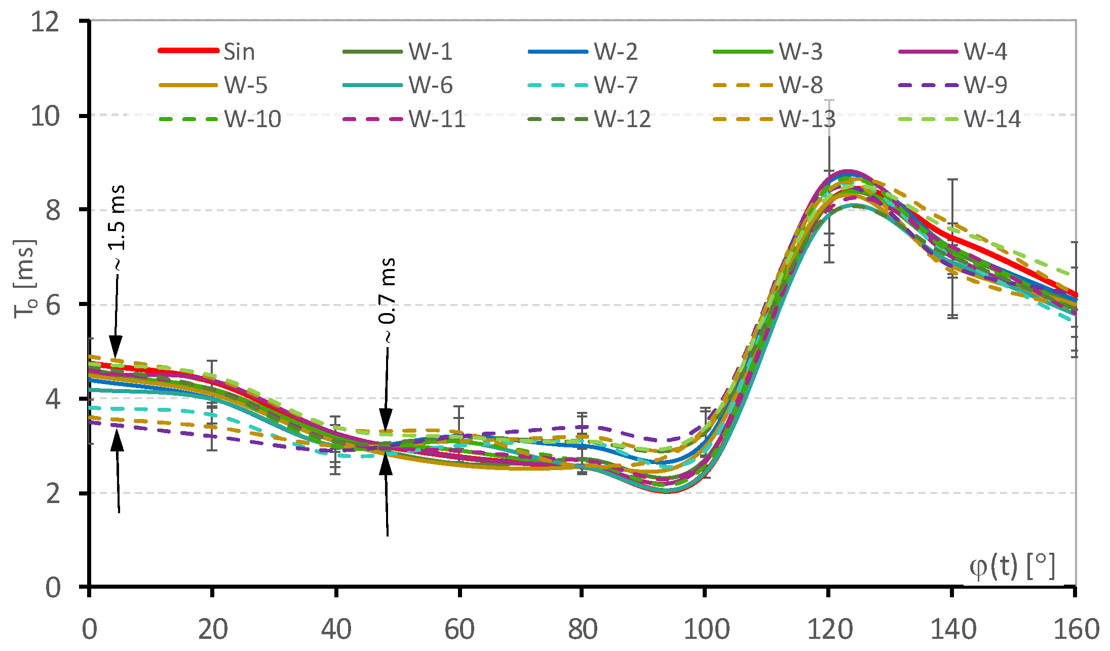
Figure 8,
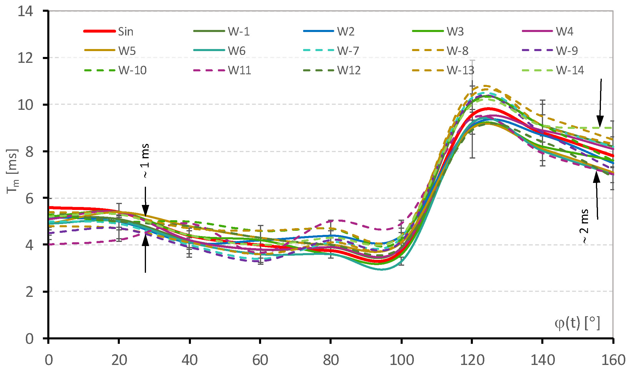
Figure 9 and
Figure 10 present the determined characteristics of the time-related dynamic parameters of EM relays operating under distorted supply voltage conditions. Movement delay time (
To), armature movement time duration (
Tm), and total switching time (
Ts) were examined as functions of the voltage switching-on phase (
φ). Each obtained diagram contains dispersions of measurement outcomes resulting from various relay model examinations and the testing of several copies of each of the tested models.
The switching time, defining the speed at which the circuit will be closed after applying the control voltage, fluctuated depending on the applied voltage. For the examined voltage waveforms, this change reached more than 10%.
A sudden increase in the relay switching time Ts for a switching phase higher than 90° is associated with a rapid decrease in the amount of electric energy supplied to the moving armature during the first half-wave of the voltage. If the average relay switching time approximately coincides with the voltage half-wave duration, this causes a rapid reduction in the velocity achieved by the moving part. This phenomenon is intensified by the fact that the voltage wave for the phase above 90° is decaying due to its falling edge presence.
The second crucial parameter with regard to EM relays is armature movement delay time. This parameter duration determines switching device response time after control voltage application. As in the case of the previous parameter, its value changed. For the examined voltage waveforms, this change was in the range of c.a. 15–25%, depending on the applied switching-on phase.
Reducing the amount of energy supplied to the drive coil in the first phase of armature movement reduces the electromagnetic force capable of counteracting the resistance forces and forces resulting from the inertia of the relay moving part. The slow reduction in the time of standstill for phases higher than c.a. 120° is, in turn, associated with the appearance of the second voltage half-wave with a rising edge. In turn, armature movement time duration changed in the range of 10–20% depending on the applied switching-on voltage phase.
Similarly, in the case of the armature movement time Tm, switching-on the supply voltage with a phase higher than 90° causes a rapid decrease in the value of the generated electromagnetic driving force. Additionally, when the voltage falling edge is reached for phases higher than 90°, it results in an additional reduction in the force generated over the movement time until the next voltage rising edge occurs.
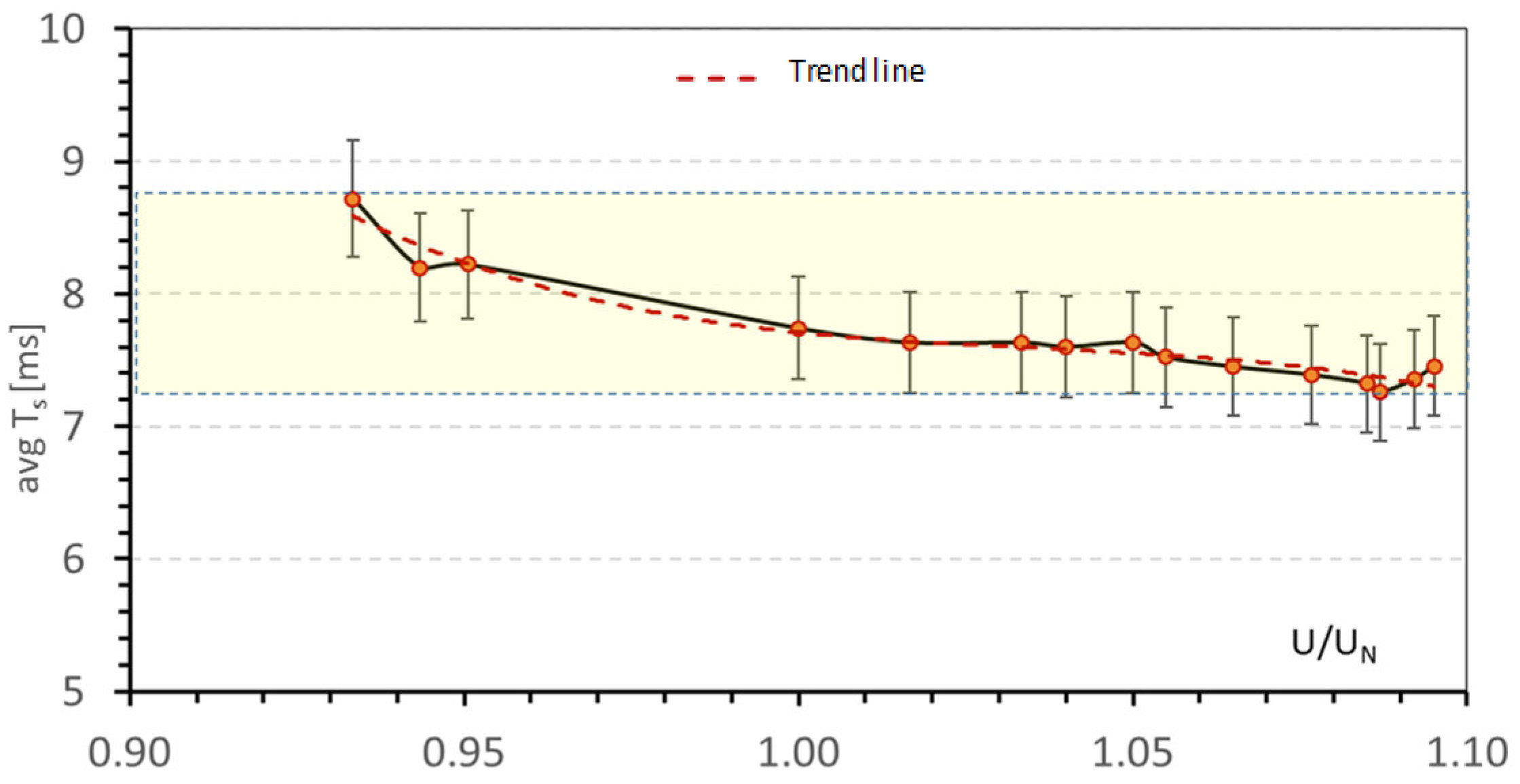
Because the occurrence of individual harmonics had a significant impact on the shape of the supply voltage and on the RMS value, the average relay switching times were determined depending on the ratio of the RMS value of the applied voltage in relation to the undistorted sinusoidal voltage (
U/
UN). The observed change in the average switching time, according to
Figure 11, was c.a. 19%.
According to the assumptions and previous analysis, applying a higher voltage to the drive coil results in a decrease in the switching time. Observed elongation of the total switching time of the relay for voltages with RMS values higher than c.a. 1.1 of the rated voltage is an effect of the occurrence of an increased number of contact bounces. Increasing the voltage RMS value results in an increase in the amount of energy supplied to the drive unit. This, in turn, results in an increased value of the generated electromagnetic driving force, which subsequently results in the moving unit achieving higher velocity and, in consequence, higher kinetic energy.
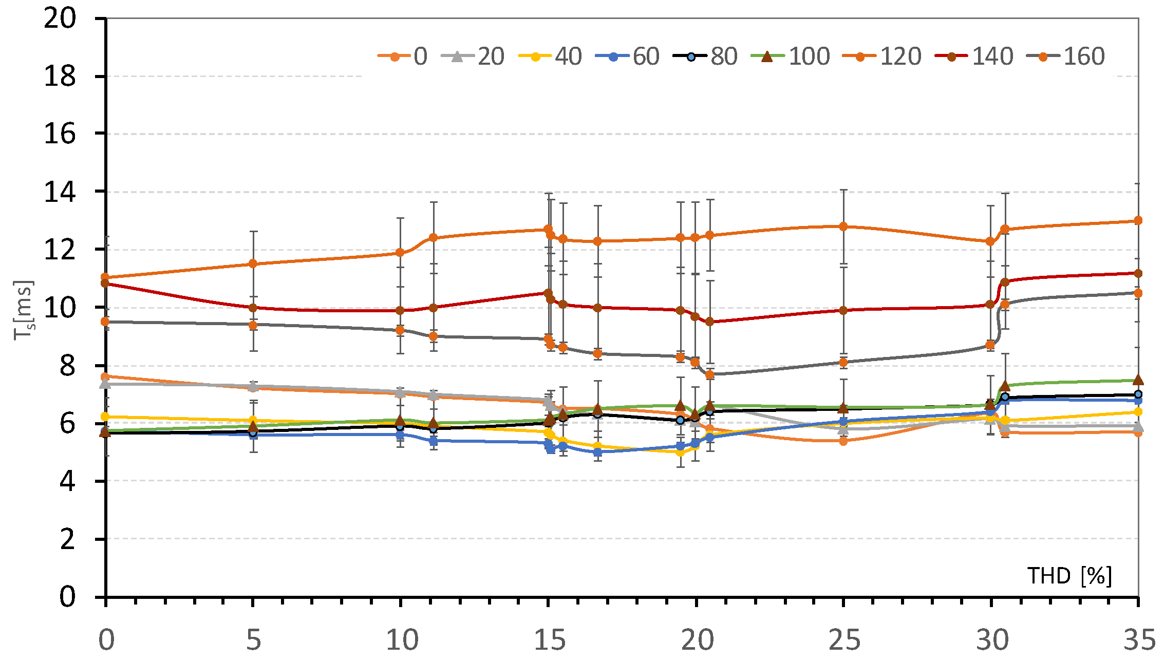
Figure 12 presents the determined impact of the
THDu parameter value on the total switching time duration
Ts. It should be noted that some of the waveforms used have the same (or similar) THD parameter values despite having different shapes.
Based on preliminary analysis, it can be stated that an increased value of the THD factor generally results in an elongation of switching time due to the higher distortion of the voltage wave. However, in this case, a detailed analysis should take into account the nature of the resulting wave deformation and not only the value of the THD factor.
Lastly, the influence of different shapes of the supply voltage wave on the average number of recorded relay contact bounces and duration of the occurred contact bounces (
Tb) was examined.
Figure 13 diagrams the average number of contacts bounced (
nb) recorded for each applied waveform and switching-on phase. As can be seen, depending on the individual harmonic content of the voltage, the number of registered contacts may change. This is related to the various volumes of kinetic energy (
Ek) the movable armature accumulates during the switching-on process.
In turn, the duration of the
Tb time for various conditions is presented in
Figure 14. Increasing the RMS voltage level resulted in an increase in the velocity of the moving armature and, consequently, an increase in the number and intensity of contact bounces. However, the reduction in the kinetic energy of the moving unit resulted in an extension of the time necessary to complete closing the relay contacts, resulting from a temporary unbalance of the driving and resistance forces.
The observed loss of contacts (loc) during switching was not frequent. The maximum number of phenomenon occurrences was recognized for W-8–W-12 waveforms at the level of 1–2 cases at 60–80° phases.
5. Summary and Conclusions
During the performed research, various distortion levels of the supply voltage controlling the EM drives coils were analyzed. According to the achieved results, harmonic pollution within the LV power network can significantly affect the operation of the EM relays. Moreover, as the dynamics parameters of the switching-on process depend on the applied voltage waveform, this may change in the range of a dozen to several dozen percent based upon the harmonic pollution level. In this connection, the real average switching time Ts may differ from values declared by the manufacturer.
What is more, the harmonic content phase had a significant impact on the resulting voltage shape. The analysis indicated a higher impact on the relay dynamics of the applied voltage form in contrast to the voltage harmonic component level specified by the THDu factor. According to the performed tests, the THDu parameter value does not clearly define the nature of changes in the signal wave and, in consequence, does not allow for a clear recognition of the impact on the dynamic parameters of the EM relays.
The key parameter determining the probability of appropriate implementation of the switching-on process is the RMS value of the applied voltage. In addition, the effectiveness of reliable contact making is determined by the shape of the voltage in the initial phase of armature movement when the kinetic energy is accumulated, which is, in turn, necessary to overcome the resistance forces in the later phase of movement.
The potential solution to the problem raised in this article is ambiguous. First of all, it is necessary to ensure the high quality of electric energy by preventing its disruption in the LV power network harmonic components. This, subsequently, involves the use of higher quality components and electronic circuits in the supplied consumer devices. Given the fact that manufacturers strive to consistently reduce device manufacturing costs, this may be very difficult. Therefore, the idea of harmonic components and additional filter usage in LV networks remains to be considered.
However, if we look at the problem from the point of view of ensuring the proper operation of the relay itself, there remains a dilemma as to whether the cost of the additional control devices or filters used will exceed the relay’s manufacturing cost. This is a problem that must be solved by the device manufacturers, who must ask themselves if it is necessary to ensure proper operation of the relay so as to ensure proper operation of the entire device, or if potential relay malfunctions will not significantly affect the operation of the device in which this relay is used.
Referring to the further research, the next step will embrace extending the scope of the measurements to include an analysis of the velocity and acceleration achieved by the relay’s movable armature (for example, using a method similar to that shown in [
11] or, alternatively, in [
23]). The measurement stand employed in the current work, which was dedicated for EM contactor analysis, was based on an internally designed electrodynamic sensor. The system was characterized by limited accuracy due to the measuring card’s relatively low resolutions. Today’s measurement equipment is characterized by having high resolution and accuracy, and nowadays, measurement methods allow for much higher accuracy of the obtained measurement results. Thus, for subsequent investigations, the previously used electrodynamic sensor will be replaced by a laser sensor that will measure armature displacements. This will allow the assessment of different EM switching device designs characterized by higher structure complexity and significantly smaller size.
