1. Introduction
Soft robotics is a young but fast-developing field. According to a systematic review [
1] for the period 2008–2022, the number of articles that were published in the field of soft robotics over the period of 2018–2022 was over 6.5 times greater than in the more than twice as long period of 2008–2017. The basic areas of application of soft robotics include the construction of bionic robots and objects, applications in rehabilitation, exploration of unknown environments, elimination of damage caused by robot collisions in production processes, and human–robot collaboration [
2]. There are at least seven types of soft materials controlled by various types of excitations, e.g., air pressure, external magnetic fields, or high voltage [
3]. This article focuses on EAPs (electroactive polymers), which are characterized by a fast response, lighter material mass, and high driven efficiency.
Dielectric elastomer actuators (DEAs) are of great interest in the field of robotic systems due to their unique properties and potential applications. These actuators are made from a class of materials known as dielectric elastomers, which exhibit large deformations in response to an applied electric field. This ability to withstand high stresses combined with their lightness and flexibility make DEAs an attractive choice for a startup in robotics systems [
4,
5,
6,
7].
DEAs offer several advantages over traditional actuators such as electric motors or pneumatic systems. First, they can achieve large actuation stresses, which enables them to produce large displacements and forces. This makes them suitable for applications requiring soft and motion-consistent movements, such as soft robotics or human–robot interaction [
8]. Secondly, DEAs have a short response time, which allows for quick operations and precise control. This is particularly beneficial in applications requiring fast and accurate movements, such as robotics or haptic devices [
9,
10]. Moreover, DEAs are lightweight and have a high power-to-weight ratio, making them suitable for use in mobile and wearable robotics. Their flexibility and extensibility also enable them to adapt to complex shapes and surfaces, enabling versatile integration with various robotic systems [
8,
11].
The main challenges in this field include the need for electronic control, an on-board energy supply, and energy autonomy, i.e., the possibility of being set in motion as a result of structural changes [
12]. Setting a soft actuator in motion is a basic engineering task. From a system perspective, a soft robot converts stored energy into useful work [
13]. The amount of energy required depends largely on the materials used. DEAP (dielectric electroactive polymer) elastomers, which are controlled using high voltages, are a special case. The energy source in DEAP-based applications is high voltages of several to a dozen or so kV [
14,
15,
16]. The use of such high voltages, even in laboratory conditions, requires special caution and may be a source of dangerous damage when testing prototypes. The issue is particularly complicated in the case of integrated actuators, which are controlled by at least two different energy sources. Examples of such structures are integrated auxetic elastomers (IAEs), which are composed of high-modulus cross-linked poly(urethane-urea) and low-modulus non-cross-linked poly(urethane-urea) [
17], and integrated soft actuators, which are composed of DEAP and MRE (magnetorheological elastomer) materials [
18].
This work presents a DEA actuator for which the membrane is integrated with the MRE disk. MREs consist of a soft elastomer embedded with magnetically responsive particles such as iron. When a magnetic field is applied, these particles align, resulting in a change in the mechanical properties of the material. By adjusting the MRE material composition, electrode design, and applied voltage, the performance characteristics of such actuators can be modeled over a wide range. One of the key advantages of DEAP integrated with MRE actuators is the ability to undergo rapid and reversible changes in stiffness and damping properties. By adjusting the strength and direction of the magnetic field, the stiffness and damping characteristics of the MRE can be precisely controlled. This enables fine-tuning of the actuator’s response, allowing for precise and adaptable movements in robotic systems [
19,
20]. Such actuators are suitable for applications that require high force output: for example, in robotic grippers. The soft structure of the actuators makes them a promising technology for soft robotics [
21,
22,
23,
24].
However, like any other mechanical system, soft actuators like DEAP integrated with MRE are susceptible to damage and wear over time. The ability to predict and detect the damage of these actuators is crucial for ensuring their reliable and safe operation. Failure of soft actuators can occur due to various factors, including mechanical stress, environmental conditions, and material fatigue. Detecting and predicting damage in real time can help prevent damage, reduce maintenance costs, and extend the efficient operation of the devices.
In recent years, researchers have focused on developing advanced techniques and methodologies for damage prediction in DEAP and MRE soft actuators [
25,
26,
27,
28]. These techniques involve different data analysis algorithms or the integration of sensors to monitor and analyze the behavior of the actuators [
29]. Our research proves that by continuously monitoring the performance and response of the actuators, it becomes possible to identify early signs of damage, such as changes in actuation displacement. The problem of damage prediction is also important because of the safety of the testing process that occurs when applying high voltages to DEAP materials. Microdamage in the soft material leads to short circuits, which may cause a fire. In this work, we examined how a few simple, interpretable features characterizing the measured motion of the actuator membrane can help predict potential upcoming damage. We prepared a small dataset with data instances consisting of individual experimental runs. We then demonstrated how machine learning methods could be used to infer a decision model that can alert to impending damage in real time as the actuator testing process progresses.
This paper is organized as follows. The second section presents the soft materials used in the analyses, the material testing methods, and the damage prediction methods.
Section 3 presents the results of the analyses carried out using examples of actuators that were correctly manufactured and actuators that were manufactured with errors that could not be detected by simple methods of measuring their physical parameters. The fourth section includes a discussion of the effectiveness and areas of potential applications of the proposed approach. The paper concludes with a summary.
2. Materials and Methods
2.1. DEAP Membrane—Carbon Suspension Preparation
A total of 2 of a mixture containing 15% carbon black BP 2000 (Cabot, Barry, UK) and 85% silicone Ecoflex 00-30 was prepared. Ecoflex 00-30 (Smooth-On, Macungie, PA, USA) is a two-component product consisting of part A and part B, which were mixed in a weight ratio of 1:1. Then 4 of octane solvent was added, and the mixture was stirred for 24 h until a homogeneous mixture was obtained. After mixing, 1.5% of catalyst based on the carbon and silicone mass (2 ) was introduced just before preparing the electrode.
2.2. DEAP Preparation
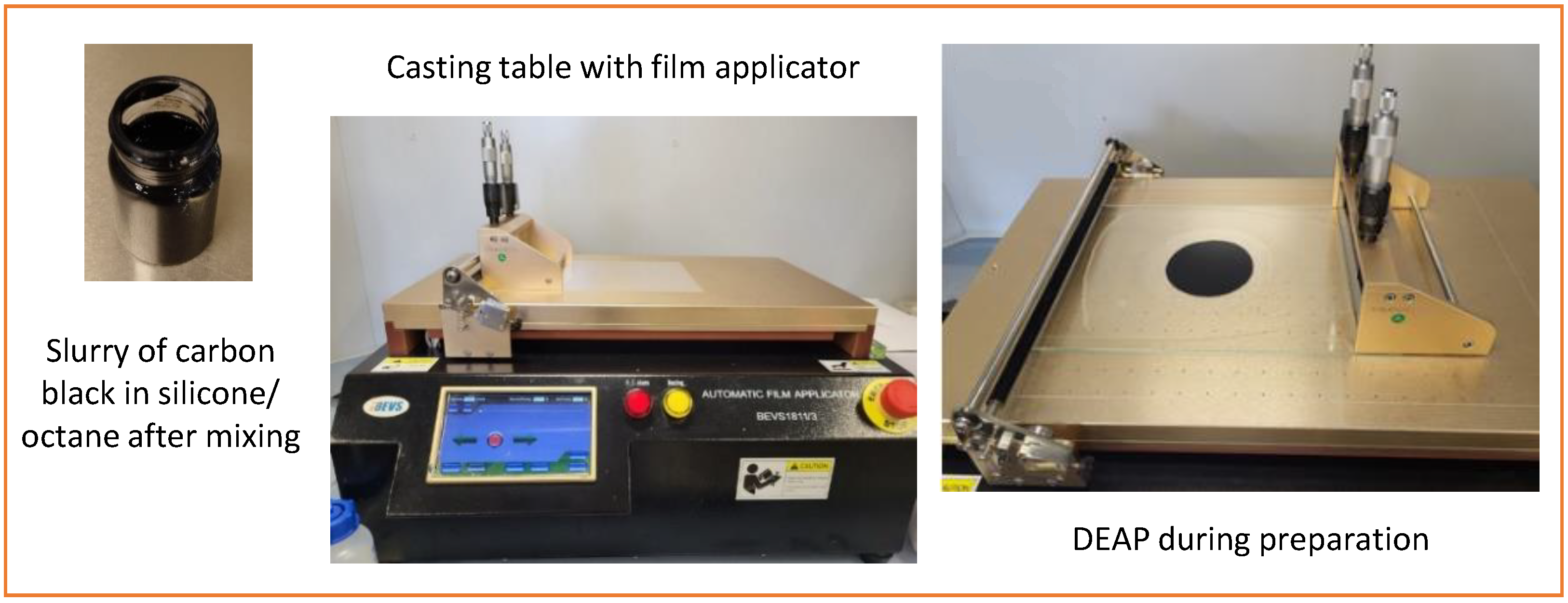
The prepared solution was poured using a casting film applicator through a mask with the shape shown in
Figure 1, and the solvent (octane) was evaporated at 50
. Then, another layer was applied, i.e., pure Ecoflex 00-30 silicone (component A:B, weight ratio 1:1) and left to cure for approximately 2–3 h. A layer of the previously prepared carbon–silicone solution was applied again to obtain another electrode layer. The thicknesses of individual layers were measured before applying the next layer. The finished DEAP was stretched by 20.8% and then mounted in a polycarbonate (PC) holder.
2.3. MRE Disc
In a vial, Ecoflex 00-30 (part A:B, mixed at a weight ratio of 1:1) was mixed with magnetic powder at a weight ratio of 7:3. As a magnetic powder, FeSiAl flakes, SP-3B (Mate Co., Ltd., Wake-cho, Japan) with a particle size of 35 –55 , was used. Then the mixture was degassed under a vacuum to remove air bubbles and cast in a mold with dimensions: diameter 30 and thickness 4 . The mixture was left to polymerize.
Then, the prepared MRE disc was attached to the previously prepared DEAP using Ecoflex 00-30 as the adhesive layer.
2.4. DEAP-MRE Actuator
Finally, the actuators were mounted in the configuration described in work [
18]. Shortly, the DEAP membrane with the MRE disc was biased with a permanent magnet (PM). The interactions between the MRE disc, the DEAP membrane, and the permanent magnet give a high distance range of motion, as described in [
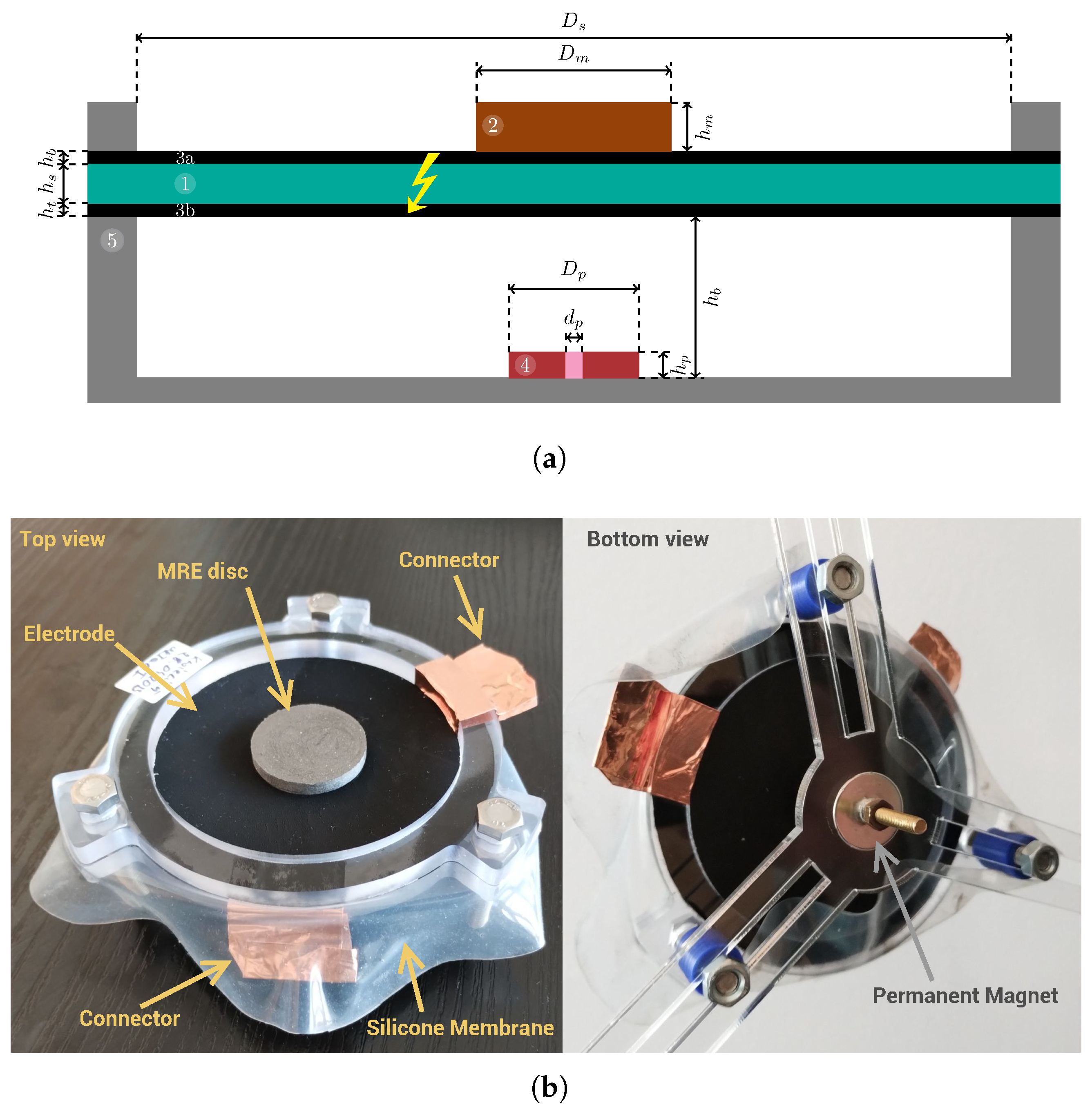
18]. The actuator was made by adding electric connectors and mounting a permanent magnet to a non-magnetic frame. The actuator scheme is presented in
Figure 2a, where all components are marked. The detailed dimensions are given in
Table 1 and
Table 2. To make the data more universal, various variants of the actuator were prepared. One set has two configurations, i.e., a short and a long distance between the permanent magnet and membrane. The second set uses two types of membranes that differ in thickness, i.e., type A—thinner and type B—thicker.
2.5. Verification Experiment
In this part, the methodology of the actuator test is briefly presented. The laboratory setup was made with a high-voltage amplifier (Trek Model 10/10B-HS), laser sensor (Micro-Epsilon optoNCDT ILD1320-25), and data acquisition board (Inteco RT-DAC/USB). The setup allowed us to measure the response of the fabricated actuator for various voltage inputs. Similar setups were also used in works [
18,
30].
Firstly, the MRE actuator is axisymmetric, so due to symmetry, the center of the disc is its maximum distance (in normal operation mode). We assume that the device is prepared to work in normal operation mode; hence, the laser sensor points to the center. Secondly, a Trek 10/10B-HS high-voltage amplifier is used for material poling, electrostatic deflection, AC or DC biasing, and various other applications. The amplifier was calibrated at global Advanced Energy service sites with proprietary technology designed to exceed industry standards. The equipment is CE compliant, and in terms of safety, it has a local safety button that allows us to immediately turn off the device and the transmitted signal. The high voltage (HV) was supplied using the original dedicated Trek high-voltage output cable with silicone rubber protection. The amplifier used in the experiments also has built-in equipment with short-circuit protection. The Trek 10/10B-HS has a built-in fault/trip status indicator that Illuminates when the HV is disabled or when the amplifier is out of regulation for more than 500 (in this instance, the HV output is not disabled). During the experiment, a safe distance of for operators from the laboratory kit was maintained. The commanded signals were additionally visualized using oscilloscopes to confirm the correctness of their ranges.
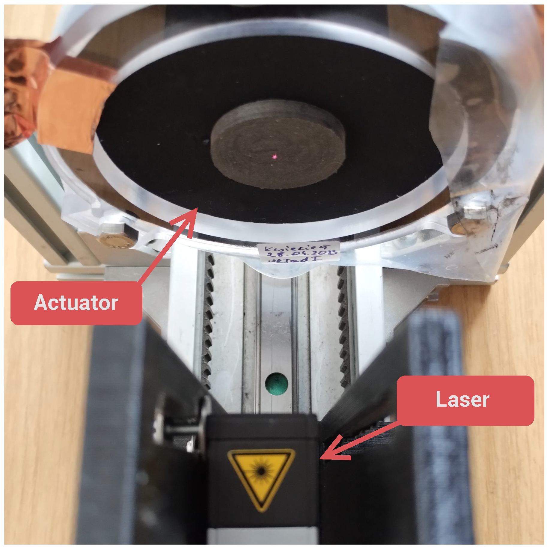
All fabricated actuators were tested on the laboratory setup presented in
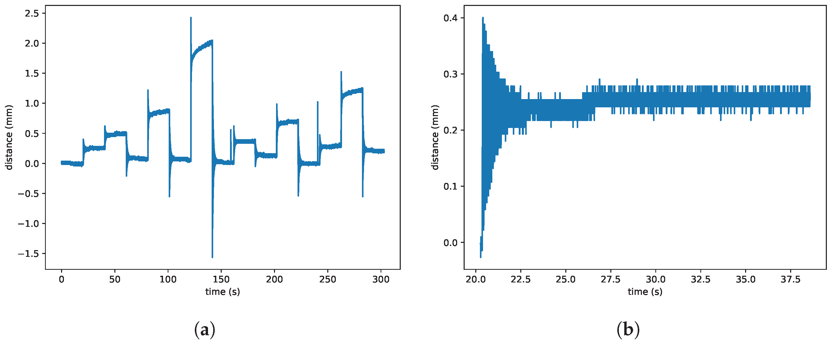
Figure 3. The following procedure was applied in the test of the actuators. A square waveform voltage was applied to the actuator with amplitude varying from 0
to 5
and period 20
, as shown in
Figure 4. Next, the motion of the actuator was measured by a laser that was pointed at the center of the MRE disc. All measured signals were acquired by the data acquisition card. During the experiment, the actuator was observed by the supervisor. If the actuator was damaged, the voltage was immediately turned off.
The dataset contains a very small number of examples from damaged actuators due to a long fabrication process and a low chance of producing a failing actuator. Another reason is that an actuator that becomes damaged cannot be used anymore, so every damaged actuator yields only one instance of data, whereas non-failing actuators can be used multiple times.
2.6. Prediction Algorithm
To develop an algorithm to predict membrane damage before it occurs, a dataset consisting of 54 series of distance measurements (49 with non-damaged actuators and 5 with damaged ones) was created. For non-damaged actuators, each series consisted of 300 s of distance values measured 1000 times per second, thus constituting 300,000 samples. For damaged actuators, the series was truncated according to expert knowledge (in all cases, this was the point at which the signal was out of range and remained constant).
Out of 49 series of non-damaged actuators, 46 had thicker membranes, and 3 had thinner membranes. This means that the class of non-damaged actuators consisted of two diverse groups, where the distances measured for the larger group (46 instances) were significantly lower than for the smaller group (3 instances).
Before further analysis, each series was subject to a median filter with a window size of three (three samples, i.e., 3 milliseconds) to remove occasional peaks in the signal (the source of the peaks was a laser sensor failing to measure the distance).
The goal of the damage prediction algorithm was to discriminate the class of damaged actuators from the class of non-damaged actuators based on simple, robust, and interpretable features. The features needed to be simple to avoid overfitting [
31] because the class of damaged actuators was extremely small—only five instances, where each instance represented only one event of failure. The rarity of the damaged actuator instances is characteristic of the problem of supervised anomaly detection, where it is typically hard to obtain labeled anomalous examples. Generating additional synthetic instances would not be trustworthy because the number of examples representing damaged actuators was so small that assuming their common properties to generate artificial instances would in itself rely on human bias and some presumed concept of similarity of the characteristics of damaged actuators. For such a small minority class, each new synthetic instance would constitute a large fraction of that class and would decrease the influence of the ground truth (real instances) on prediction in favor of artificially generated data.
Let us denote by the moment of time when the damage occurred and by the moment of time that is before the damage. is the lead time. We are interested in features of the recorded time series that would allow us to distinguish any non-damaged actuator sequence from any damaged actuator sequence for the highest —i.e, to find some feature of the signal that occurs as early as possible before the damage, is present in all instances of damaged actuators, and is not present anywhere in non-damaged actuator instances. Note that with a long enough lead time before the damage event, the series that represents damaged actuators becomes indistinguishable from that of non-damaged ones.
For this reason, when considering discriminating features of the analyzed signal, for each feature, we calculate:
Then, we calculate the maximum of these values for all non-damaged actuator instances (MaxNondamaged) and the minimum of these values for all damaged actuator instances (MinDamaged). If MaxNondamaged < MinDamaged, this means that such a feature can perfectly discriminate the damaged and non-damaged actuator instances for a given lead time because its most extremely low value for any damaged actuator series ahead of failure is still higher than the highest value at any time for any non-damaged actuator series.
3. Results
According to the procedure described in the previous section, the tests on DEA were performed with the step voltage as the input and the distance as the output. In
Figure 4, the transient of the voltage is shown. An example response without damage is visible in
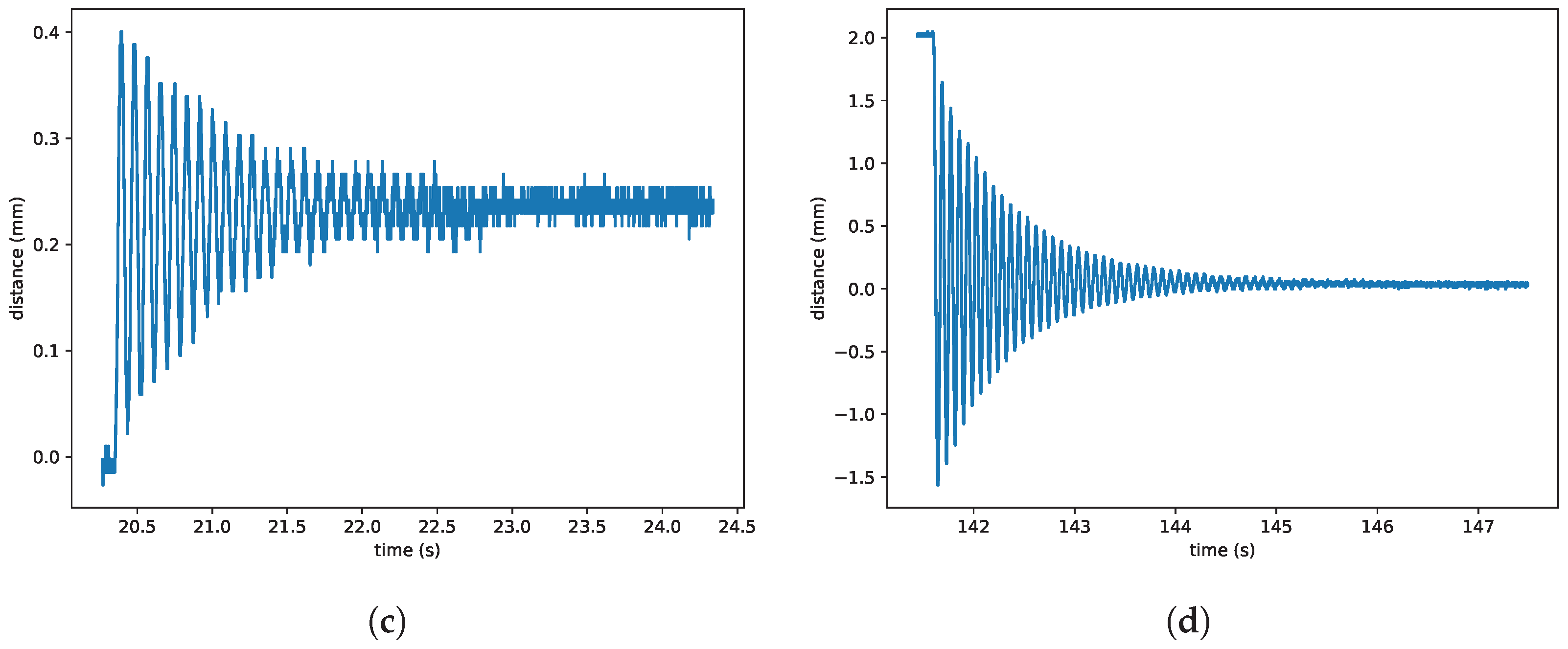
Figure 5a–d. It can be seen that the response consists of the slow relaxation part (
Figure 5c) and the fast oscillations (
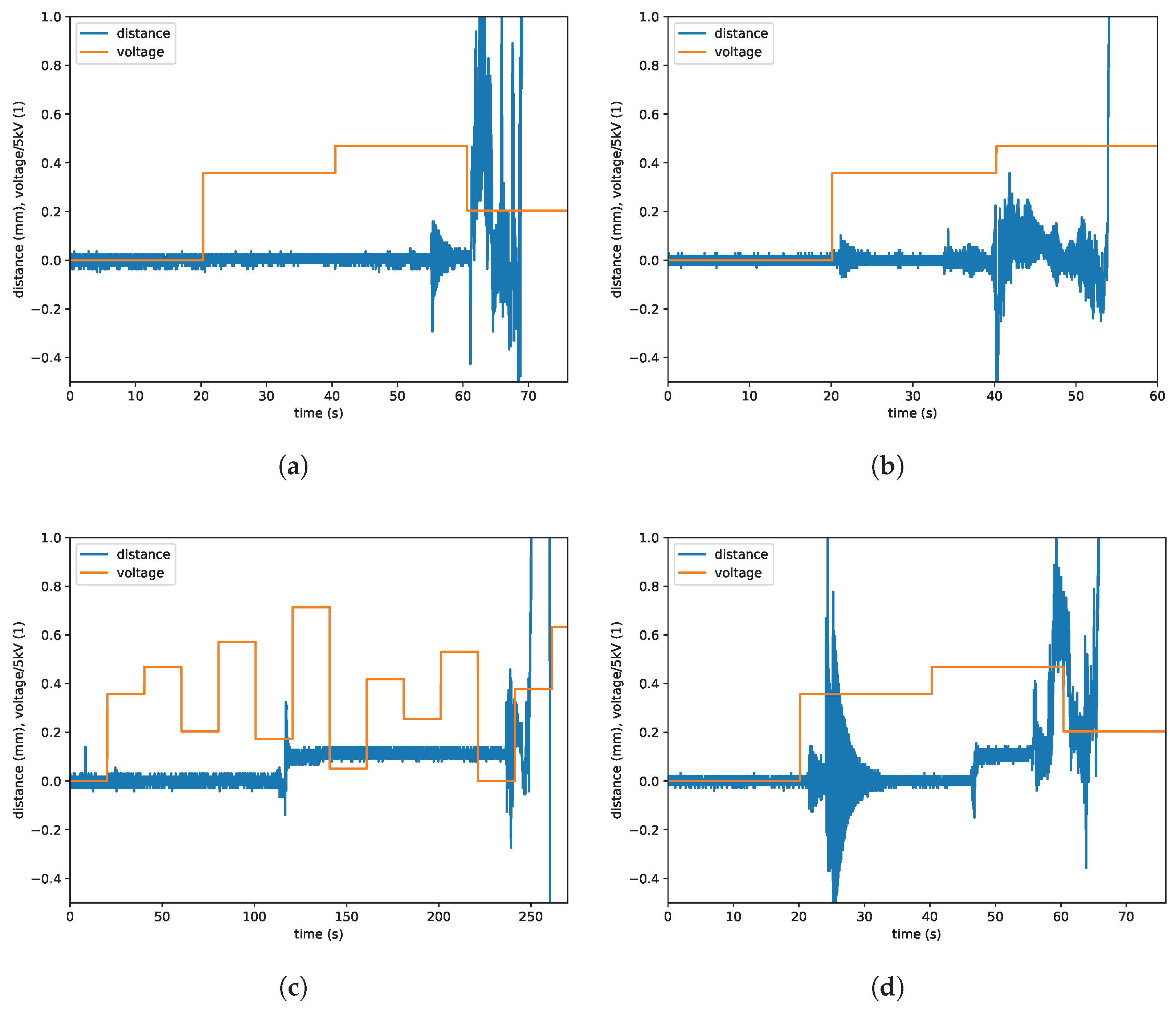
Figure 5d). The actuator was supervised by the investigator, who turned off the voltage immediately in the event of a failure. An example of four runs with failures is presented in
Figure 6.
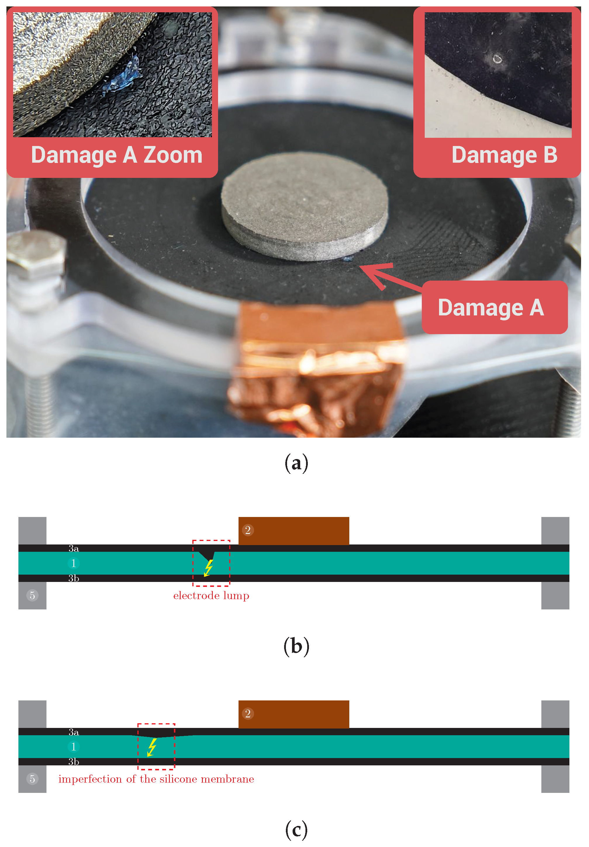
Figure 7a shows an example of damaged actuators (for two different membranes). The possible causes of the damage, such as electrode lumps and imperfections in the silicone membrane, are shown in
Figure 7b,c respectively.
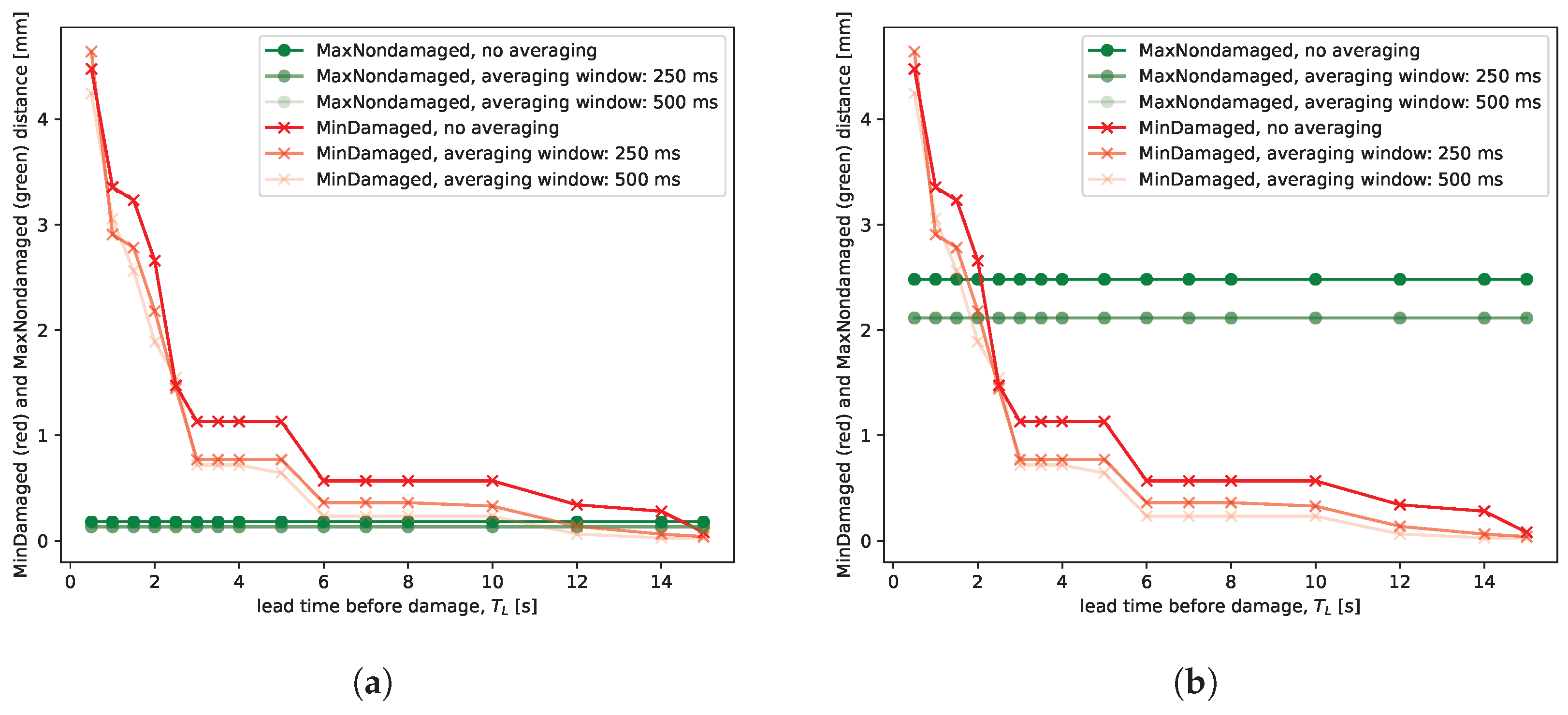
Regarding the damage prediction algorithm, for which the goal was to discriminate the class of non-damaged actuators from the class of damaged actuators as early as possible before the damage event, a number of simple, robust, and interpretable features were investigated. The features included the absolute distance, the absolute discrete difference of the distances, the absolute ratio of the discrete difference to the raw distance, combinations of the distance response and voltage excitation, and smoothing signal operators with various averaging windows (50 to 500 ms). Smoothing the signal with various averaging windows deteriorated class separation gradually as the size of the averaging window increased (
Figure 8). Overall, from this set of features, the best class separation and the highest interpretability were demonstrated by the raw distance feature. The absolute discrete difference of the distances could be helpful for class separation as well depending on the inclusion of the “A” actuator in the non-damaged actuator class and the lead time before failure—see the distribution of classes along the vertical axis in
Figure 9a.
Figure 8 demonstrates the extreme values of distance for the damaged and non-damaged actuator classes. Intuitively, distances for all non-damaged actuators fall below the green line throughout the entire experiment, and distances for all damaged actuators up to
before failure are above the red line.
As previously noted, the non-damaged actuator class included results from the “A” actuator, which was thinner than the others. Due to higher oscillations, this series makes it more difficult to distinguish it from the damaged actuator instances. The plots demonstrate that when “A” is excluded from the non-damaged actuator class (46 instances), it is possible to predict the event of failure at least 14 s before it occurs. When “A” is included in the non-damaged actuator class (46 + 3 instances), the prediction time drops to 2 s. Note that these values are pessimistic and represent the worst-case scenario, i.e., this is the time before the failure that is guaranteed for any series in the dataset (the red line is the lower envelope of the damaged actuator class), and the lead time is at least as long for all instances.
From the analysis of
Figure 8, it is possible to determine the distance threshold value that would stop the experiment before actuator damage. For example, when the absolute distance exceeds 3 mm, the experiment would be stopped at least 1 s before the damage, even if A-like actuators are being tested (
Figure 8b). The 1 s lead time is a pessimistic (i.e., conservative) estimate based on the damaged actuator that was most difficult to distinguish from the non-damaged actuators. If we knew that A-like actuators are not being tested in the experiment, the absolute distance threshold of approximately 0.5 mm would allow us to stop the experiment at least 6 s before the damage (
Figure 8a).
The damaged actuator class is too small (only five instances) to expect generalization or to obtain meaningful values from the estimation of predictive accuracy metrics [
31]. However, the dataset allows us to demonstrate the application of machine learning methods to the problem of predicting actuator damage. Assuming that two features (attributes) are used: maximum absolute distance and maximum discrete difference of distances, the values of these features for all recorded instances and for
s are shown in
Figure 9a.
For such a dataset, the automated procedure of tree induction, CART (classification and regression trees) [
32], using the entire dataset for training produces the decision tree shown in
Figure 9b. In this decision tree, the root node contains all 54 instances and is not pure—both classes are included: 49 non-damaged actuator instances and 5 damaged ones, thus yielding a positive Gini impurity value. The majority class is non-damaged actuators (49 instances). The condition to split the dataset into two parts of zero impurity (so that no more splits are required) uses the distance feature. The result of this tree induction is interpreted as follows: if one wants to predict actuator damage at least 1 s before it occurs, based on the examples from the dataset, one should stop the experiment as soon as the absolute distance exceeds the threshold of 2.917 mm.
For the current dataset, we do not want to develop complex classifiers because of the extremely small size of the damaged actuator class, but this example demonstrates the scalability of the machine learning approach. Given a higher number of instances and a more representative minority class, it would be reasonable to apply machine learning algorithms to discover (and statistically test and validate using train–test splits) various models for the prediction of actuator damage, just as demonstrated above.
Even though the very small size of the minority class (five instances) and the small size of the entire dataset do not justify the expectation of the model’s generalizability beyond that dataset, calculating the geometric mean metric (G-mean—the root of the product of class-wise sensitivity [
33,
34]) for
s using five-fold stratified cross-validation yields the following G-mean values for the folds: (1.0, 1.0, 1.0, 0.0, 0.816), thus giving an average of 0.763. For
s, the model uses two features instead of one and is therefore more complex. Then, the G-mean values in testing folds are (1.0, 1.0, 1.0, 1.0, 0.816), which yields an average of 0.963, suggesting more robust prediction, but this is only because of a specific, favorable distribution of sparse instances in the feature space. Due to the small number of instances, the cross-validation score may vary considerably depending on the assignment of particular instances to particular folds.
4. Conclusions
In this work, we presented a comprehensive study on the predictive modeling of damage in integrated dielectric elastomer actuator (DEAP) and magnetorheological elastomer (MRE) soft actuators. Our research aimed to address the critical need for reliable damage prediction methods in these complex and versatile soft actuators. Thanks to experiments conducted on many actuators, we have gained valuable information about the failure mechanisms and performance degradation factors affecting the operation of actuators. Our findings highlight the significance of considering the maximum absolute distance and the maximum discrete difference of distances in damage prediction models for soft actuators. We demonstrated the effectiveness of the automated tree induction CART procedure for predicting the onset of actuator damage, thus enabling future implementation of protection strategies that increase overall actuator reliability. The developed damage prediction approach can be used to optimize the design and performance of integrated DEAP and MRE actuators for various applications. Furthermore, the validation of experimental results in diverse operating conditions and environments is essential for ensuring the reliability and applicability of predictive models. Collaborative efforts between researchers from various disciplines, including materials science, mechanical engineering, and robotics, can facilitate comprehensive testing and validation of soft actuator systems under different scenarios and use cases. By continuing to refine predictive models, explore new materials, and validate experimental findings, researchers can unlock the full potential of integrated DEAP and MRE soft actuators and pave the way for transformative advancements in robotics and beyond. In terms of future directions, there are several avenues for further exploration and development. One area of focus could be the refinement and optimization of predictive models using advanced machine learning algorithms. By leveraging large datasets generated from experimental testing, researchers can train more accurate and robust models for predicting actuator damage and performance degradation.
