Article

Combined Analytic Hierarchy Process and Weighted Interval Method Models for the Geological Evaluation of CO2 Storage in Coal Goaf

1
College of Geology and Environment, Xi’an University of Science and Technology, Xi’an 710054, China
2
College of Energy Engineering, Xi’an University of Science and Technology, Xi’an 710054, China
*
Author to whom correspondence should be addressed.
Energies 2024, 17(11), 2672; https://doi.org/10.3390/en17112672
Submission received: 7 May 2024 / Revised: 25 May 2024 / Accepted: 29 May 2024 / Published: 31 May 2024
(This article belongs to the Special Issue Advances in Carbon Capture and Storage and Renewable Energy Systems)

Abstract

:
The increasing concentration of CO2 in the atmosphere is a major factor contributing to climate change. CO2 storage in coal goaf is a convenient, effective, and economical solution. Methods to quickly and effectively evaluate geological conditions are urgently required. The main influencing factors are geological safety, storage potential, economics, and environmental protection; these include 4 aspects, 38 indexes, and 4 index levels that can be quantified using classification levels. We established a geological evaluation model, using analytic hierarchy process (AHP) and weighted interval methods. AHP was used to determine its elements, indicators, and inter-layer relationships, as well as to clarify its structural relationships. The weight interval method is used to evaluate unstable elements, reducing their difficulty, and constant values are used to assign weights of stable elements to increase accuracy. This model was applied to assess the suitability of the goaf in Yaojie mine for geological CO2 storage. The results revealed that this goaf is an above average CO2 storage space, which was consistent with previous research. This geological CO2 storage evaluation model may also be used to assess the CO2 storage suitability of other coal goafs.

1. Introduction

Carbon dioxide (CO2) is one of the most abundant greenhouse gases [1,2]. Significant emissions of CO2 trap heat in the Earth’s atmosphere, causing global temperatures to increase in a phenomenon known as the greenhouse effect. Indirect effects include polar ice-cap melting and climate alterations, which can lead to a rise in sea levels and the inundation of low-altitude land [3,4]. Several techniques have been developed to mitigate the release of CO2 and mitigated the impact of climate change. Carbon capture and storage (CCS) is a significant solution that uses large-scale technology to mitigate climate change by removing CO2 emissions from fossil-fueled power plants [5,6,7]. As it is currently impossible to completely abandon fossil energy sources, CCS is the primary technical method and supporting guarantee to achieve the temperature control goal of the Paris Agreement [8].
CO2 storage, which presents one of the most difficult challenges for CCS technology, can be divided into three categories: mineral storage, oceanic storage, and geological storage. The mineral storage of CO2 is a chemical reaction between CO2 and metal oxides to form solid carbonates and other by-products [9,10,11]. This storage method has the advantages of a lengthy storage time and low regulatory costs, but the high cost of the energy and reactants required for the storage process presents issues. The ocean storage of CO2 consists of injecting CO2 to form hydrates that are disposed into the ocean at great depths, or injecting CO2 at great depths into the ocean to liquefy or form hydrates under suitable conditions [12]. Submarine earthquakes or water pressure releases can cause CO2 leakages. This results in ocean acidification [13], which affects marine life and causes disturbances to ecosystems. The geological storage of CO2 uses a mechanism that mimics the storage of fossil fuels in nature. CO2 is injected through pipelines into strata with specific geological conditions and at specific depths. Geological environments such as old oil and gas fields, difficult-to-exploit coal seams, and deep groundwater layers are often used for CO2 storage [14]. Geological storage is considered to be a more effective method for the long-term storage of CO2 because of site feasibility and economic aspects, among other issues. As of November 2020, 28 CO2 storage reservoirs were active in the global within geological structures, and 37 others were in development.
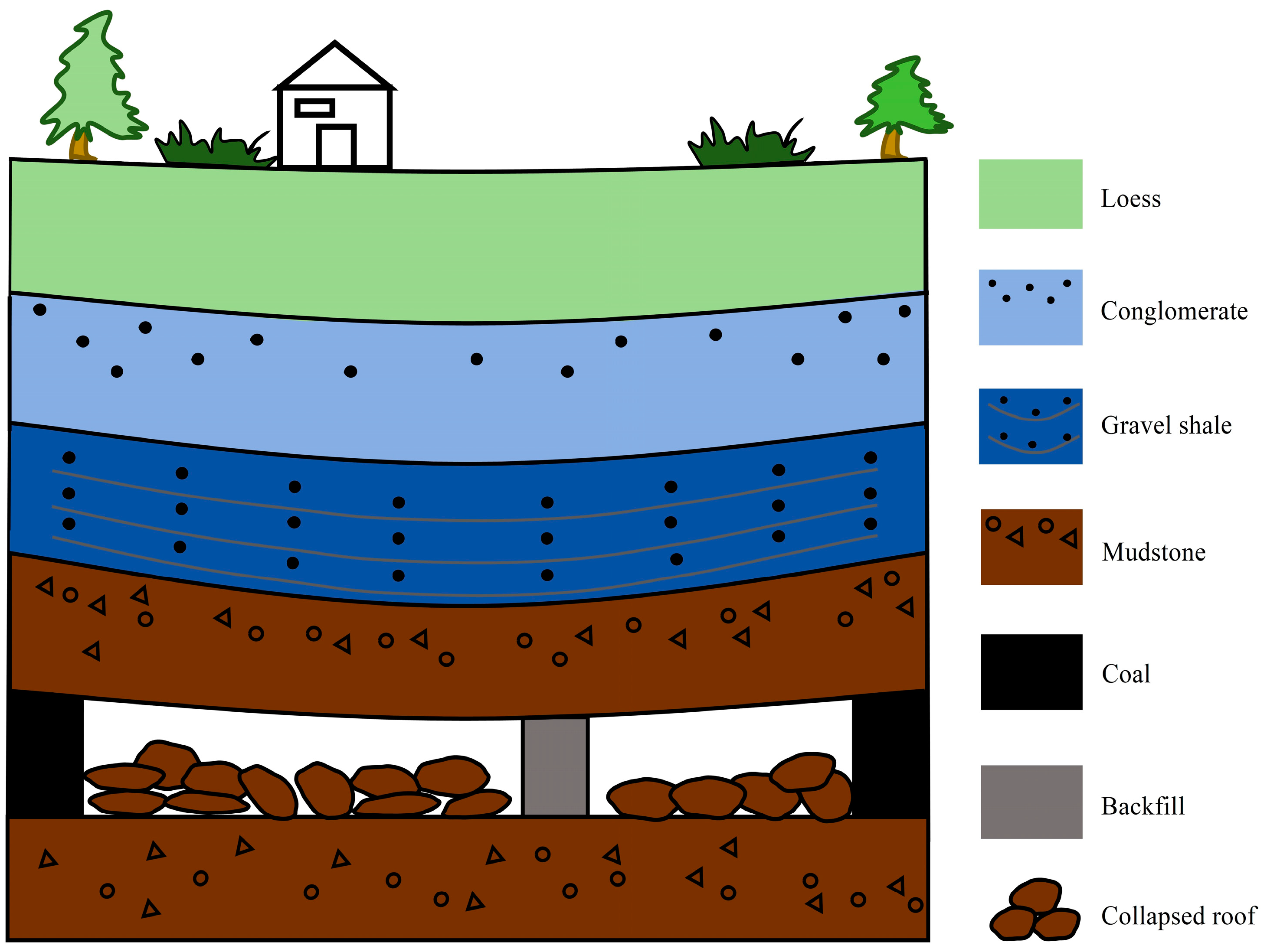
CO2 is a predominant greenhouse gas in the Earth’s atmosphere. A major source of anthropogenic CO2 is the combustion of fossil fuels. Coal is an important fossil energy source and industrial raw material. It is the largest and most abundant fossil energy material in China [15]. The total amount of CO2 emitted by coal combustion has more than doubled in the past 20 years because of the continuous increase in total energy consumption (Figure 1). The characteristics of China’s energy structure have been defined as “lacking oil, little gas, rich coal”. This identifies coal resources as the main energy source and this structure does not change [16]. Under the goal of carbon neutrality, coal enterprises must seek breakthroughs and participate in the carbon emission market. Finding CO2 geological reservoirs and developing simple and inexpensive storage technologies are particularly important for the in situ storage of CO2. Large areas of underground goaf containing fractured zones are formed, providing significant potential space for CO2 underground storage (Figure 2). The geological storage of CO2 in coal goaf with good cap rocks is an interesting option.
Fossil-fuel power plants in China are the main consumers of coal and, consequently, the largest industrial fixed-point source of CO2 emissions. This extensive use of coal provides convenient CO2 storage potential in goaf areas to achieve the sustainable development concept of “where does coal originate and where do the solid waste and CO2 generated from coal use return to?”. Comparatively, the cap rock of goaf is intact and closer to the CO2 production area.
The storage of CO2 in goaf has significant advantages compared with other geological storage methods. Goaf (Figure 2) can represent a vast area; the collapse area formed by the collapse of the overlying strata in goaf has a much larger porosity and geometric size of voids than other geological reservoirs. This results in a much lower CO2 injection pressure than other storage methods. The tunnels and chambers not only provide a significant area for CO2 storage but can also be used as overpressure storage tanks in combination with appropriate sealing measures [18,19]. Mines also accumulate detailed geological data during long-term mining processes that other geological storage methods cannot provide.
Currently, only feasibility studies on the storage of CO2 in coal goaf exist [20,21,22,23]. The geological conditions of CO2 storage in goaf are rarely evaluated. It is necessary to study the geological conditions of CO2 storage because CO2 leakage can harm groundwater, organisms, and the environment. Effective methods to evaluate the geology are urgently required. In this study, we establish a mechanism for CO2 storage in coal goaf and evaluate the geological characteristics to provide a reference for CO2 storage in goaf.

2. Methods and Materials

2.1. Methods of CO2 Geological Storage

CO2 geological storage is the most direct and effective method of reducing carbon emissions. Common underground storage methods include using deep saline aquifers in sedimentary basins [24,25], oil and gas fields [26,27], unminable deep coal seams [28,29], and post-mining salt karst cavities [30]. Researchers have proposed the use of CO2 to replace CH4 or oil for the extraction and storage of CO2 [31]. The exploration of CO2 geological storage methods has primarily focused on deep storage (over 1000 m), with disadvantages such as slow injection rates, high displacement pressure, high comprehensive investment costs, obvious geological constraints, long distances from CO2 production concentration areas, and the inability to store CO2 on a large scale. It is necessary to identify widely distributed, convenient, and low-cost storage areas for CO2 potentially at the expense of a certain storage capacity under the premise of safety according to the Chinese situation.
The critical pressure of CO2 is 7.38 MPa, and its critical temperature is 31.1 °C (Figure 3a). CO2 remains in a liquid state despite temperature changes when the pressure exceeds 7.38 MPa. The density of CO2 in the process of CO2 geological storage gradually increases with an increase in the injection depth, but the change is minor. The density of CO2 reaches a supercritical state when the depth reaches or exceeds 800 m (Figure 3b).
The burial depth of coal in China is generally 500–1000 m. The feasibility of CO2 storage in the goaf of medium and shallow coal mining is a topic of concern for Chinese geologists [14,20,21,22,23,33]. A pilot experiment for CO2 storage was conducted in the Southern Shanxi Formation of the Qinshui Basin in Shanxi Province (buried at depths of 472.34~478.70 m), with an injection of 192.8 tons of liquid CO2. The storage effect was satisfactory [14,33]. Wang et al. [21] studied the occurrence conditions of natural CO2 in the Yaojie mining area of Gansu Province (<400 m) and concluded that it is feasible to store CO2 in coal goaf. The geological evaluation of CO2 storage in coal goaf provides a reference for the future geological storage of CO2 in coal goaf.

2.2. Mechanism of CO2 Storage in Coal Goaf

The mechanism of CO2 storage in goaf is divided into physical trapping and chemical trapping.

2.2.1. CO2 Physical Trapping

The physical storage mechanisms include geological trapping and bound residual CO2 trapping.
(1)
Geological trapping
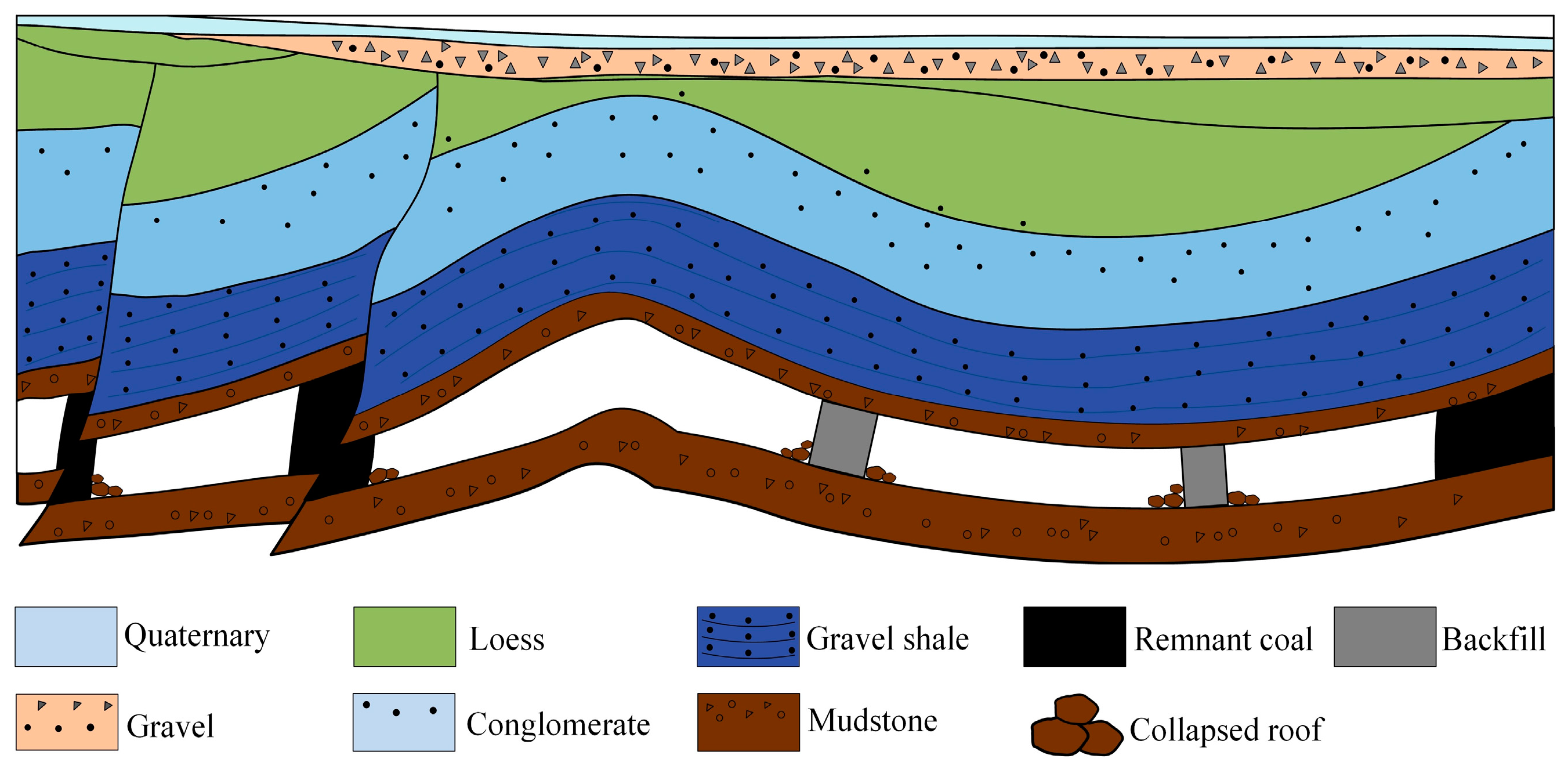
Geological trapping uses the upper structure of a reservoir space (the associated after-effects of tectonic or orogenic processes) to prevent the upward migration of CO2 under buoyancy, thereby of storing CO2. A stratigraphic trap, a structural trap, or a combination of both can support CO2 storage. Such structures are suitable for normal-pressure storage. Traps include anticlines and closed faults, illustrated in Figure 4. Liu et al. [19] proposed the rebuilding of storage facilities in goaf for supercritical CO2 storage. The mining depth (500–1000 m) of coal mines in China represents middle and shallow layers, permitting storage under normal pressure. Stable roadway spaces can be stored in artificially reconstructed storage tanks with a supercritical storage capacity.
(2)
Residual CO2 trapping
An amount of CO2 exists in the pores of a medium because of the effects of capillary force, surface tension, and organic carbon adsorption. The carbon content and porosity in the cover layer, the internal surface area (20–300 m2/g), and the coal pillar of coal seams are higher; thus, CO2 is more easily absorbed [34]. The properties of the cover layer are similar to those of the coal seam, potentially permitting storage of up to 60 m3 (standard temperature and pressure, or STP) CO2 per ton of coal at relatively low gas pressures of approximately 5 to 6 MPa [35]. Coal seams and cover layers can store at least five times (even ten times, for the most captive and porous layers) the quantity of gas that is traditionally contained within a classical reservoir rock.

2.2.2. CO2 Chemical Trapping

The chemical storage mechanisms include solubility trapping and mineral trapping.
(1)
Solubility trapping
Solubility trapping is the dissolution of CO2 in underground fluids. The solubility of CO2 in water is influenced by the temperature, pressure, and salinity of the water. These factors affect the storage time.
(2)
Mineral trapping
Mineral trapping is the fixation of CO2 by carbonate minerals through a reaction with certain components of the surrounding rock (phyllosilicate minerals) and water (sulfate). It is affected by the storage depth, salinity, and pH value of the fluid and the mineral composition of the surrounding rock. Mineral carbonation is a low-temperature/low-pressure process, making it feasible for use in relatively shallow geological settings.

2.3. Geological Evaluation Methods

2.3.1. Introduction to AHP and WIM Models

Studying the geological conditions of CO2 storage in goaf can not only prevent CO2 leakage to the surface or near-surface environment but also ensure that health, safety, and environmental issues are addressed. Thus, a comprehensive analysis of the geological conditions of CO2 in the goaf of coal is necessary. Geological CO2 storage involves still-immature technology, especially in the goaf of coal. There is also a lack of an evaluation system to assess the suitability of coal goaf for geological CO2 storage. In this study, we used the results of previous studies from CO2 storage sites such as deep salt water, oil and gas reservoirs, unminable coal seams, and karst cavities. They were all geologically evaluated using AHP [34].
AHP is a decision-making method that decomposes elements always related to decision making into different levels such as goals, criteria, and schemes. Qualitative and quantitative analyses can then be conducted [36]. AHP divides the various factors within these complex problems into interconnected or orderly layers, thereby rationalizing complex problems and assigning quantitative relative importance values (i.e., weighting) to each layer using fuzzy logic approaches. The geological storage of CO2 in the goaf of coal is influenced by numerous complex factors such as geology, geography, and technology, as well as environmental, political, and economic variables.
AHP, which has a fixed factor weight, cannot process certain situations where the order is chaotic because of the importance of elements in complex systems as well as possible uncertainties between the criteria and index. An AHP based on the weighted interval method (WIM) can effectively process the fixed weight of a traditional AHP. A weight determined by the experts is amalgamated with the cognition of factors. This ensures that the interval weight is closer to the real result. The core of interval weight theory is to enable experts to assign factor weights, enhance the sensitivity to risk, and reduce the risk of the whole process to maintain each expert’s perception of risk factors.

2.3.2. Methods of AHP and WIM Models

The methods of AHP and the WIM models prevent the influence of potential risk factors and reveal the impact of potential risks on the evaluation system. The calculation procedure of the AHP and WIM models is as follows.
First, the geological evaluation grade of the research area is determined. The evaluation of the potential and suitability for CO2 geological storage in China is classified from low to high accuracy into national grade, basin grade, target area grade, site grade, and injection grade [37]. Guo et al. [38] classified CO2 storage sites into regional grade, basin grade, target area/target area grade, and site grade by adjusting the in scale and evaluation methods. Previous classification standards [37,38] divide the CO2 storage sites in coal goaf into regional grade, mine field grade, mine grade, and perfusion grade based on the distribution characteristics and discontinuity of the goaf in coal. The object, or the scale size of data collection, and field investigation of CO2 storage sites are determined according to the degree of work in the research area (Table 1).
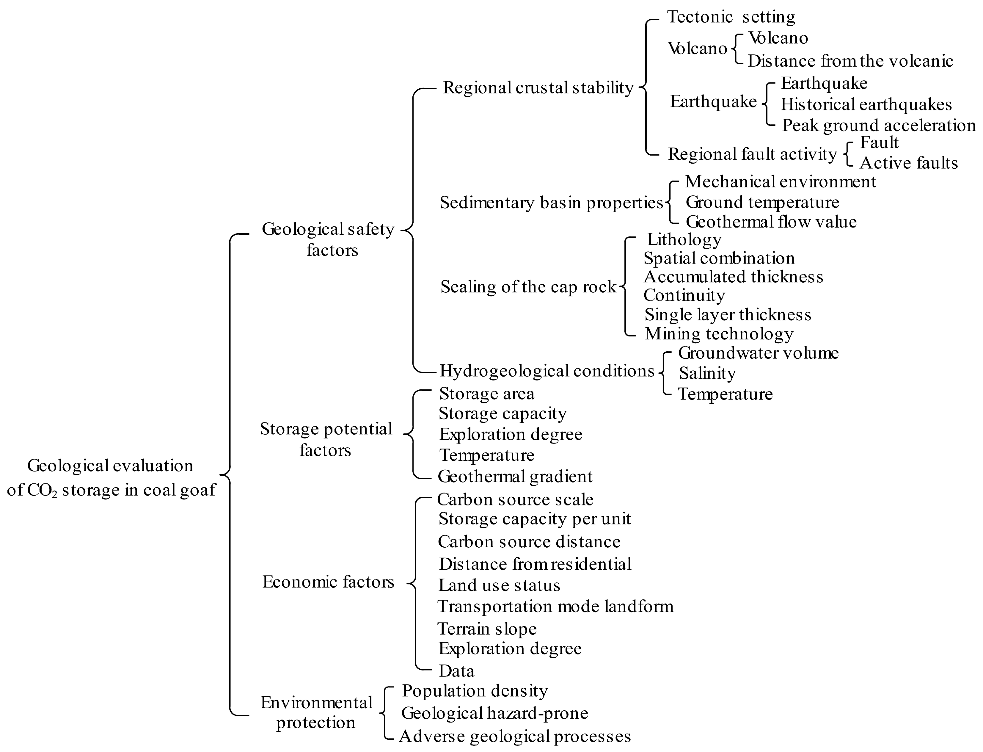
Second, a hierarchy consisting of three different elements (goal, criteria, and scheme) is built. AHP is used to determine the elements, indicators, and inter-layer relationships to clarify the structural relationships. The evaluation index system of the hierarchical analysis structure is established by selecting the geological safety, storage scale, social environmental risk, and economic suitability based on the principles of economic, moderate scale, and environmentally friendly CO2 geological storage locations (Figure 5). The comprehensive evaluation includes 4 aspects, 38 indicators, and 4 index levels. There may be significant differences in the actual evaluation process of micro-indicators in certain regions, such as permeability and land cover ratio. These are added to the indicator layer.
Third, the evaluation units are divided and refined using a GIS grid. The evaluation units for CO2 storage are divided based on structures (faults, folds) and tunnels, etc., as boundaries. Their corresponding reserves can then be measured.
Fourth, the raw data are non-dimensionalized. The raw data are first standardized because of the significant dimensional differences between different indicators. The non-dimensional data all between 0 and 1, compared with the standard, can be combined with the geological conditions of CO2 storage facilities at home and abroad [37,38,39]. The main influencing factors for the storage conditions of oil, natural gas, and coalbed methane are the geological safety factors, storage potential factors, socio-economic factors, and environmental protection factors. CO2 storage is then appropriately classified. Each indicator is then allocated into one of the following four levels (see Section 3.2 for the classification): suitable ([0.75, 1.00]), relatively suitable ([0.50, 0.75]), generally suitable ([0.25, 0.50]), and unsuitable ([0, 0.25]). Each block in a study area can then be assigned and recorded as matrix R.
R = [ r 11 r 22 r ii r nn ]
Fifth, a judgment matrix is established. The weights of various factors and indicators can be compared with each other by experts. The importance level is calculated based on the collected data and field research results, e.g., gij is a comparison result of the importance of element i and element j. The judgment matrix is formed by comparing the results of pairwise factors. The quantitative scale used to compare the importance of elements is presented in Table 2.
G = [ g 11 g 12 g 1 n g 21 g 22 g 2 n g i 1 g i 2 g i n g n 1 g n 2 g n n ]
where is gik + gki = 1, 0 ≤ g ≤ 1.
Certain risks decrease or disappear with an increase in the degree of the understanding of unknown things in the process of field investigations and data analyses. The influencing factors can then be divided into unstable and stable factors. Stable factors do not significantly with time or there is a clear understanding of them. Unstable factors are those that undergo significant changes over time or have controversial perceptions of them. Unstable elements can be evaluated using the WIM when assigning weights to reduce their difficulty. Stable elements use values to assign weights to increase the accuracy.
Judgment matrices with different values may be produced because of differences in the cognition of experts on various elements and indicators. The interval method is used to integrate the weight matrix. [gik, gik+] is expressed in the matrix; gik is the minimum value of the expert evaluation weight, and gik+ is the maximum value.
G = [ [ g 11 , g 11 + ] [ g 12 , g 12 + ] [ g 1 n , g 1 n + ] [ g 21 , g 21 + ] [ g 22 , g 22 + ] [ g 2 n , g 2 n + ] [ g i 1 , g i 1 + ] [ g i 2 , g i 2 + ] [ g i n , g i n + ] [ g n 1 , g n 1 + ] [ g n 2 , g n 2 + ] [ g n n , g n n + ] ]
Finally, the comprehensive evaluation values of each block are calculated to evaluate the geological storage level of the block.
P = R * G = [ r 11 r 22 r i i r n n ] * [ [ g 11 , g 11 + ] [ g 12 , g 12 + ] [ g 1 n , g 1 n + ] [ g 21 , g 21 + ] [ g 22 , g 22 + ] [ g 2 n , g 2 n + ] [ g i 1 , g i 1 + ] [ g i 2 , g i 2 + ] [ g i n , g i n + ] [ g n 1 , g n 1 + ] [ g n 2 , g n 2 + ] [ g n n , g n n + ] ]
The minimum P value is calculated by multiplying the interval weight of the element or index with the grade. Suitable areas [0.75, 1.0], above average [0.50, 0.75], average areas [0.25, 0.5], and unsuitable areas [0, 0.25] are divided in the map by comparing the standard values.

3. Results and Discussion

3.1. An Example of CO2 Geological Storage in Goaf

3.1.1. Geological Setting of the Study Area

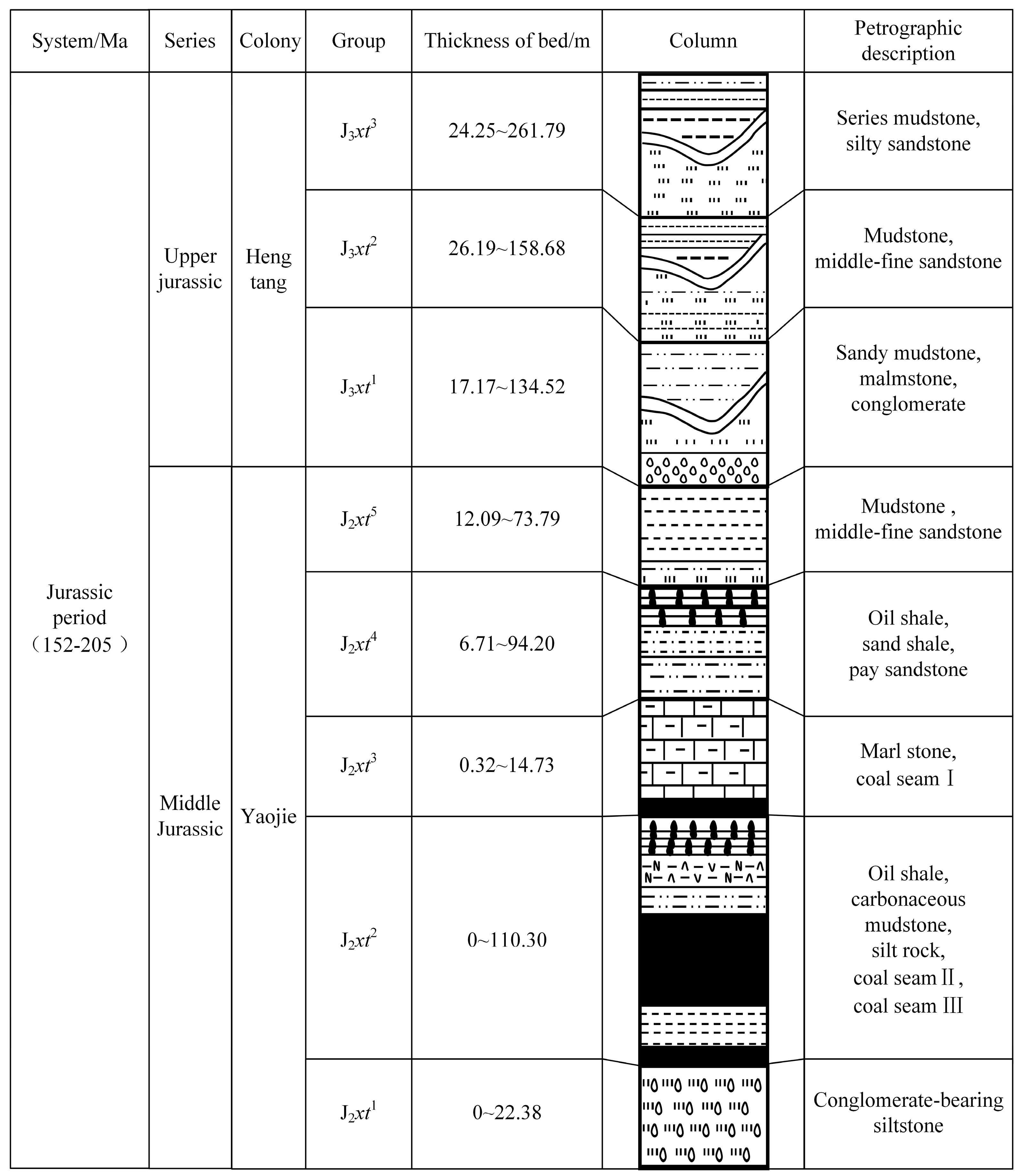
We selected the Yaojie mining area in Gansu Province as the research area. The Yaojie mining area is located northwest of the Minhe Basin. The faults in the mining area, both compressive and torsional, are extremely developed, and there is an NNW basement fault structure at the eastern end of the area. The overlying strata comprise the Yaojie and Hengtang groups, which consist of multiple sets of mudstone, sandstone, and shale (Figure 6). The overlying strata are the Yaojie and Hengtang groups, consisting of multiple sets of mudstone, sandstone, and shale. The burial depth of the coal seam is 320–380 m, and the coal thickness is 30 m. The mining area was divided into six units based on the structural distribution. The old goaf of the mining area was selected as an example for evaluation.

3.1.2. Classification of Influencing Factors

The main influencing factors were geological safety, storage potential, socio-economic, and environmental protection. These were based on the storage conditions of oil, natural gas, and coalbed methane combined with the geological conditions of CO2 storage facilities at home and abroad [37,38,39].

Geological Safety Factors

Geological safety factors can be subdivided into regional crustal stability, sedimentary basin properties, cap rock sealing, and hydrogeological conditions.
(1)
Regional crustal stability
The risk of CO2 escape remains because of the changes in temperature and pressure in the earth, as well as sudden geological events such as volcanoes and earthquakes caused by tectonic movements. Regional crustal stability includes the tectonic setting as well as volcanic, earthquake, and regional fault activity.
1) Tectonic setting
The tectonic background of the research area was a concrete manifestation of the long-term stability of the crust within the area, potentially affecting the stability of the long-term storage of CO2 in the goaf. We divide the tectonic setting into cratonic basins, inland rift basins, passive continental margin basins, and strike slip fault basins based on the stability of the coal-forming basins. The corresponding levels are presented in Table 2.
2) Volcano
Volcanic activity can penetrate the upper and lower strata, simultaneously producing faults and fractures can destroy the sealing of the CO2 cap rock. The volcanic development zone and distance from the volcanic zone were used to evaluate volcanoes. The specific classification is listed in Table 2.
3) Earthquake
The geological storage of CO2 in goaf is classified as grade I of the ‘Seismic Safety Evaluation of Engineering Sites (GB 17741-2005)’ [40], which refers to the storage standards of nuclear waste. The peak acceleration of ground motion, historical earthquake, the distance from the earthquake zone, and other indicators were used to evaluate earthquake (Table 3). The peak ground acceleration was ascertained using the ‘China Seismic Parameter Zoning Map (GB18306-2001)’ [41] from the ‘China Seismic Peak Ground Acceleration Zoning Map’.
4) Regional fault activity
We referred to the relevant nuclear power plant specifications in China for the regional fault activity requirements for CO2 geological storage in goaf (Table 3). There were no active faults within a 10 km radius of the site. An active fault was defined as a fault movement that occurred between 10,000 and 35,000 years ago, with small-scale seismic activity and multiple historical seismic events recorded by instruments. The possibility of surface displacement might remain.
(2)
Sedimentary basin properties
The study of sedimentary basin properties during CO2 geological storage mainly considers the stress environment, geothermal flow value, and geothermal temperature. In this study, we divided the sedimentary basins were divided into compression, compression-torsion, torsion, tension–torsion, and tension based on the dynamic environment of current sedimentary basin deformation data combined with the escape channels of a CO2 geological storage structure.
From the data in Table 4, we concluded that the lower the values of geothermal heat flow and surface temperature, the more conducive the site to CO2 storage.
(3)
Sealing of the cap rock
The sealing of the cap rock is a prerequisite for CO2 storage in the goaf of coal; it is also the factor most studied by scholars. Downey [42] and Ingram et al. [43] proposed a process for comprehensive evaluation from both micro and macro perspectives. Li et al. [44] established an analytical model to ascertain the stability of cap rocks under injection production disturbance as well as a numerical model to evaluate the sealing performance of the combined cap rock. Geological macro-factors, including the lithology, thickness, continuity, spatial combination, and mining technology, were used to evaluate the sealing performance of the cap rock (Table 5).
1) Lithology
The lithology of common cap rocks in coal includes marl, mudstone, shale, argillaceous siltstone, and sandstone. There are significant differences in the mineral composition, pore throat structure, and physical properties of the rock types. The higher the clay content in the cap rock, the lower the porosity and permeability of the rock layer, the higher the displacement pressure, and the stronger the sealing ability of the cap rock. Indicators such as the mud ratio or mud–sand ratio are used to evaluate the sealing ability of cap rocks [45,46]. The toughness of rocks also affects the sealing of the cap rock. In general, brittle rock strata are more likely to produce fractures and cracks than ductile rock strata. The higher the clay mineral content, the stronger the rock toughness. Overall, the sealing capacities of marl, mudstone, shale, argillaceous siltstone, and sandstone decreases in sequence.
2) Cap rock thickness
The cap rock thickness is the main evaluation index of sealing. Hubbert [47] observed that mudstone a few inches thick could seal an oil column hundreds of meters high. When the cap rock is thin, it is often unstable; this is unfavorable for large-scale CO2 geological storage. A thick layer is not easily damaged by small faults, making it difficult to form connected micro-cracks. Wang et al. [48] obtained empirical data through experiments and believed that a 20 or 30 m thick coal seam roof could be used as an effective sealing thickness. In this study, we determined the thickness of the cap rock for CO2 storage by referring to the thickness data of the cap rock for oil and gas storage (Table 5).
3) Continuity of cap rock
The continuity of cap rock is an important factor in the large-scale enrichment of CO2. The thicker the cover layer, the larger the area, the better the continuity of lateral distribution and the safer the storage of CO2. CO2 storage in the goaf of coal must prevent unsealed boreholes in the process of coal exploration as well as prevent the development of faults and fractures in the cap rock. A fracture can result in the cap rock completely losing its sealing ability, especially when the fault throw is greater than the thickness of the cap rock and the fracture zone is open.
4) Cap rock space combination
CO2 storage in goaf must possess a good regional cap layer to prevent the direct leakage of CO2. In general, a single geological cap rock that meets the sealing capacity requirements can effectively store CO2. CO2 leakage may occur if the geological cap rock breaks because of factors such as earthquakes. The continuity of faults is destroyed during the long-term storage period. An overlying multi-level cap rock structure can achieve secondary interception or sealing after the direct cap rock fails if there is a multi-layer sealing combination on the direct cap rock to form a multi-level cap structure. This prevents the further upward leakage of CO2 after breaking through the direct cover layer. Thus, the cap rock space combination is measured by the sealing ability of the cap rock. The better the quality and the greater the number of secondary cap rocks, the stronger the secondary interception and sealing ability, the higher the long-term safety, and the lower the risk of CO2 geological storage.
5) Coal mining technology
Coal mining technology affects the continuity of CO2 storage roofs. The filling and fallen method are used to process the roofs in goaf. The filling method results in little damage to the roof. The cap rock remains relatively complete, which is conducive to effective CO2 storage. The fallen method causes significant damage to the roof, which then requires the consideration of factors such as the burial depth, coal mining thickness, and cover layer thickness.
(4)
Hydrogeological conditions
The influence of hydrogeological conditions on the occurrence and migration of coalbed methane and natural gas includes hydraulic migration and dissipation as well as hydraulic sealing [49,50]. The storage of CO2 in goaf uses space in the coal goaf. The storage space is affected if filled with water. If the amount of groundwater is not significant and contains chemicals; it reacts with CO2 and plays a role in mineral solidification. The hydrogeological conditions for CO2 storage in goaf are evaluated before CO2 filling. The indexes considered include the groundwater volume, the groundwater temperature, and salinity (Table 6).

Storage Potential Factors

The storage potential is an important factor when evaluating CO2 storage in goaf. Only goaf areas that can store a large amount of CO2 have the necessary conditions for development and use. The evaluation indicators include the storage area, storage capacity, exploration degree, surface temperature, and geothermal gradient. The specific classification parameters are presented in Table 7.

Economic Factors

Economic factors are important factors for the implementation of CO2 storage in goaf. The main indicators include the carbon source scale, storage capacity per unit area, carbon source distance, land use status, transportation mode, landform, distance from residential areas, and exploration level (Table 8). These indicators were ascertained based on the China Agenda 21 Management Center and previous research [38,51]. A larger carbon source scale means a more concentrated carbon source, a closer carbon source distance, a lower CO2 transportation cost, worse land use, a higher exploration degree, more data support, and a greater distance from residential area, with more suitability for CO2 storage.

Environmental Protection

Environmental protection is an indispensable element in engineering construction. The evaluation indexes of CO2 storage in goaf include population density, geological-hazard-prone areas, and adverse geological processes. The lower the population density, the fewer the geological-disaster-prone areas. The fewer the adverse geological effects, the greater the suitability for CO2 storage (Table 9).

3.1.3. Index Weight Determination

The judgment matrix G required by AHP was obtained from an evaluation of the experts’ comparisons of the modal particles in each element. The matrix of the first-level index was obtained as follows.
G = [ 0.50 0.80 0.75 0.70 0.20 0.50 0.45 0.30 0.25 0.55 0.50 0.40 0.30 0.70 0.60 0.50 ]
Stable factors were assigned a fixed value, and unstable factors were assigned an interval value based on the comparison matrix of the geological status and factor importance of the study area. The individual weightings for all evaluation indexes related to the suitability of an assigned coal goaf for geological CO2 storage were calculated using AHP. Table 10 lists the resulting values.

3.1.4. Classification of Geological Conditions for CO2 Storage

The matrix values of the influencing factors in the study area were determined using the factors listed in Table 2, Table 3, Table 4, Table 5 and Table 6 and the values of the comparison criteria. For example, the fourth level parameters (D) were subject to membership matrix.
R 4 = [ 0.80 0.90 0.80 0.80 0.90 1.00 0.60 0.75 0 0 0.50 0 ]
The data in Table 2, Table 3, Table 4, Table 5 and Table 6 characterized the similarity degree matrix outlined for the other grading indexes. The following example illustrates a matrix for class C reservoir characteristics, class B internal conditions, and class A comprehensive index evaluation matrix values.
R 3 = [ 1.00 1.00 0.80 0.70 0.825 0.80 [ 0.768 , 0785 ] 0.60 0.935 0.75 0.75 0.80 0.635 0 0.80 0 0 0 0.60 0 ]
R 2 = [ 0.657 0.40 1.00 0.91 0.60 0.70 0.90 [ 0.684 , 0.866 ] 0.90 0.90 0.90 0.72 1.00 0.80 1.00 0 0.85 0.70 0 0 0 1.00 0 0 0 1.00 0 0 0 0.90 0 0 0 0.90 0 ]
R 1 = [ [ 0.684 , 0.873 ] [ 0.595 , 0.695 ] [ 0.755 , 0.833 ] [ 0.685 , 0.945 ] ]

3.2. Comprehensive Evaluation

The weight vectors and index degree matrix were combined with the weighted average algorithm to determine a comprehensive evaluation vector for the suitability of the Yaojie coal mine to geologically store CO2.
P = R 1 * G = [ [ 0.684 , 0.873 ] [ 0.595 , 0.695 ] [ 0.755 , 0.833 ] [ 0.685 , 0.945 ] ] * [ [ 0.45 , 0.55 ] 0.10 [ 0.15 , 0.25 ] 0.20 ] = [ 0.62 , 0.95 ]
The principle of the minimum suitable value indicated that the goaf of the Yaojie coal mine represented an above average location for the geological storage of CO2. These results were similar to the results [38] of a geological CO2 storage assessment of goaf performed by the Shaanxi Provincial Key Laboratory of Geological Support for Coal Green Exploitation, indicating that the approach outlined in our research produced effective and reasonable results. Our evaluation results for CO2 geo logical storage had a certain reference significance.
The geological evaluation of CO2 storage in the goaf of coal mainly comprised 4 categories, 4 levels, and 38 indexes. The selected indicators, which were macro-factors, covered geological safety, storage potential, and economic and environmental protection factors. We used the storage conditions of oil, natural gas, and coalbed methane combined with the geological conditions of CO2 storage facilities at home and abroad for the evaluation indicator selection process. Thus, the selected indexes involved a wide range of factors and were complete.
The WIM effectively reduces the engineering risk and evaluation difficulty. It is difficult to quantify uncertain factors such as the population density and geological hazards of environmental protection indicators. Currently, experts have greater certainty and spend less time on evaluation when using the WIM because it uses minimum values to evaluate the grade, thereby reducing the evaluation risk.
Compared with traditional CO2 storage suitability evaluation, this method inherits the hierarchical classification and logical relationship construction in traditional evaluation methods. The weight of the traditional evaluation method is determined according to the importance between the indicators. However, it is difficult to use fixed values to measure the importance of each indicator in the actual evaluation process. The weight interval method used to reduce the difficulty of comparing the importance of indicators and better handle the differences between indicators. At the same time, the principle of using the minimum appropriate value can reduce the risk and make the environment more friendly in the comprehensive evaluation.
Certain issues remain regarding the selection of indicators for this evaluation method, including the non-consideration micro-indicators. The shale content in sandstone is relatively low in certain areas and the permeability is low; thus, this may represent good cap rock.

4. Conclusions

(1) In this study, we outlined a method to evaluate the suitability of geological CO2 storage in the goaf of coal. We divided the influencing factors into multiple macro-indicators and quantified them using classification levels. Our method combined the principles of safety, economy, and environmental protection to reduce evaluation difficulties and improve safety whilst ensuring economic feasibility and environmental friendliness.
(2) We combined our approach with the characteristics of coal goaf to develop a hierarchical index system model that could be applied to the comprehensive evaluation of any assigned coal goaf. The WIM was used to weight each indicator. This reduced the issues of weight allocation and risk, thereby providing reference values for the future assessment of the geological CO2 storage potential of coal goaf. Furthermore, it provides theoretical support for CO2 storage strategies and climate change mitigation.
(3) Our geological CO2 storage assessment model was adopted to assess the geological storage potential of the goaf of Yaojie mine. This evaluation indicated that the basin is an above average area for coalbed geological CO2 storage.

Author Contributions

D.H.: conceptualization, methodology and writing—original draft; Y.X.: visualization, writing—review and editing; L.L.: supervision, writing—review and editing; C.H.: data curation and investigation. All authors have read and agreed to the published version of the manuscript.

Funding

This research was funded by the Excellent Young Scientists Fund (no. 52222404), the Shaanxi Province key research and development plan ”two chains” integration key project (nos. 2023-LL-QY-07), the Key Research and Development Program of Shaanxi Province (no. 2023-YBGY-283), and the Scientific Research Program funded by Xi’an Science and Technology Bureau (grant no. 22GXFW0064).

Data Availability Statement

The raw data supporting the conclusions of this article will be made available by the authors on request.

Conflicts of Interest

The authors declare that they have no known competing financial interests or personal relationships that could have appeared to influence the work reported in this paper.

References

  1. Osman, A.I.; Hefny, M.; Abdel Maksoud, M.I.A.; Elgarahy, A.M.; Rooney, D.W. Recent advances in carbon capture storage and utilization technologies: A review. Environ. Chem. Lett. 2020, 192, 797–849. [Google Scholar] [CrossRef]
  2. Malik, S.; Makauskas, P.; Karaliute, V.E.; Pal, M.; Sharma, R. Assessing the geological storage potential of CO2 in Baltic Basin: A case study of Lithuanian hydrocarbon and deep saline reservoirs. Int. J. Greenh. Gas Con. 2024, 133, 104097. [Google Scholar] [CrossRef]
  3. Leung, D.Y.; Caramanna, G.; Maroto-Valer, M.M. An overview of current status of carbon dioxide capture and storage technologies. Renew. Sustain. Energy Rev. 2014, 39, 426–443. [Google Scholar] [CrossRef]
  4. Hurlbert, M.; Osazuwa-Peters, M. Carbon capture and storage in Saskatchewan: An analysis of communicative practices in a contested technology. Renew. Sustain. Energy Rev. 2023, 173, 113104. [Google Scholar] [CrossRef]
  5. Li, Q.; Wang, Y.L.; Wang, F.L.; Wu, J.P.; Tahir, M.U.; Li, Q.C.; Yuan, L.; Liu, Z.H. Effect of thickener and reservoir parameters on the filtration property of CO2 fracturing fluid. Energ. Source. Part A Recovery Util. Environ. Eff. 2019, 42, 1705–1715. [Google Scholar] [CrossRef]
  6. Ramadhan, R.; Abdurrahman, M.; Bissen, R.; Maneeintr, K. Numerical simulation of potential site for CO2 sequestration in a depleted oil reservoir in northern Thailand. Energy Rep. 2023, 9, 524–528. [Google Scholar] [CrossRef]
  7. Li, Q.C.; Liu, J.; Wang, S.M.; Guo, Y.; Han, X.Y.; Li, Q.; Cheng, Y.F.; Dong, Z.; Li, X.Z.; Zhang, X.D. Numerical insights into factors affecting collapse behavior of horizontal wellbore in clayey silt hydrate-bearing sediments and the accompanying control strategy. Ocean Eng. 2024, 297, 117029. [Google Scholar] [CrossRef]
  8. Sattar, U.; Latief, R.; Wang, Y.D.; Sattar, A.S. Green financial reporting framework for Paris Agreement parties. Front. Environ. Sci. 2024, 12, 1335547. [Google Scholar] [CrossRef]
  9. Weiler, J.; Tassinari, C.C.G.; De Aquino, T.F.; Bonetti, B.; Viola, V.O. Using mining waste for CO2 sequestration: Exploring opportunities through mineral carbonation, nature-based solutions, and CCUS. Int. J. Minin. Reclam. Environ. 2024, 2318132. [Google Scholar] [CrossRef]
  10. Fang, Z.Y.; Gao, Y.H.; He, W.; Zhu, M.B.; Xia, L.; Yang, P.Y.; Liu, D.S.; He, J. Carbonation curing of magnesium-coal slag solid waste backfill material: Study on properties of flow, mechanics and carbon sequestration. Case Stud. Constr. Mater. 2024, 20, e03204. [Google Scholar] [CrossRef]
  11. Fang, Z.Y.; Liu, L.; Zhang, X.Y.; Han, K.M.; Wang, J.Y.; Zhu, M.B.; Sun, W.J.; He, W.; Gao, Y.H. Carbonation Curing of Modified Magnesium-Coal Based Solid Waste Backfill Material for CO2 Sequestration. Process Saf. Environ. Prot. 2023, 180, 778–788. [Google Scholar] [CrossRef]
  12. Hassanpouryouzband, A.; Joonaki, E.; Vasheghani Farahani, M.; Takeya, S.; Ruppel, C.; Yang, J.; English, N.J.; Schicks, J.M.; Edlmann, K.; Mehrabian, H.; et al. Gas hydrates in sustainable chemistry. Chem. Soc. Rev. 2020, 49, 5225–5309. [Google Scholar] [CrossRef] [PubMed]
  13. Ali, M.; Jha, N.K.; Pal, N.; Keshavarz, A.; Hoteit, H.; Sarmadivaleh, M. Recent advances in carbon dioxide geological storage, experimental procedures, influencing parameters, and future outlook. Earth Sci. Rev. 2022, 225, 103895. [Google Scholar] [CrossRef]
  14. Shen, W.J.; Ma, T.R.; Zuo, L.; Yang, X.; Cai, J.C. Advances and Prospects of Supercritical CO2 for Shale Gas Extraction and Geological Sequestration in Gas Shale Reservoirs. Energy Fuels 2024, 38, 789–805. [Google Scholar] [CrossRef]
  15. Sang, S.X. The demand and mode of low-carbon development in carbon neutral coal industry. In Blue Book of Low Carbon Development, State Power Investment Group Co., Ltd., China International Economic Exchange Center; Social Science Literature Publishing House: Beijing, China, 2021; pp. 146–151. [Google Scholar]
  16. Wang, G.F.; Ren, S.H.; Pang, Y.H.; Qu, S.J.; Zheng, D.Z. Development achievements of China’ s coal industry during the 13th Five-Year Plan period and implementation path of “dual carbon” target. Coal Sci. Technol. 2021, 49, 1–8. [Google Scholar] [CrossRef]
  17. Annual Report Working Group on the Collaborative Path between Carbon Neutrality and Clean Air in China. Annu. Rep. China’s Carbon Neutrality Clean Air Synerg. Pathw. 2023, 2023, 3–10.
  18. Xie, G.; Liu, L.; Suo, Y.L.; Zhu, M.B.; Yang, P.; Sun, W.J. Study on the green disposal of industrial high salt water and its performance as activator to prepare magnesium-coal based solid waste backfill material for mine. J. Clean. Prod. 2024, 452, 141933. [Google Scholar] [CrossRef]
  19. Liu, L.; Wang, S.M.; Zhu, M.B.; Zhang, B.; Hou, D.Z.; Huan, C.; Zhao, Y.J. CO2 storage-cavern construction and storage method based on functional backfill. J. China Coal Soc. 2022, 47, 1072–1086. [Google Scholar] [CrossRef]
  20. Wang, S.M.; Shen, Y.J.; Sun, Q.; Liu, L.; Shi, Q.M.; Zhu, M.B.; Zhang, B.; Cui, S.D. Underground CO2 storage and technical problems in coal mining area under the “dual carbon” target. J. China Coal Soc. 2022, 47, 45–60. [Google Scholar] [CrossRef]
  21. Wang, S.M.; Kou, H.B.; Shen, Y.J.; Liu, L.; Gu, L.J.; Chen, X.; Li, Z.Y. Implications of CO2 outburst from coal⁃bearing rock series for the CO2 geological sequestration under shallow layers. J. Green Mine 2023, 1, 33–47. [Google Scholar]
  22. Li, S.G.; Zhang, J.F.; Bao, R.Y.; Ding, Y.; Bai, Y.; Zhou, Y.X.; Zhu, B. Research on the characteristics of CO2-water interface and the law of dissolution and mass transfer under the condition of carbon sequestration in goaf. J. China Coal Soc. 2024, 49, 513–527. [Google Scholar] [CrossRef]
  23. Ding, Y.; Tang, Y.Z.; Li, S.G.; Zhao, C.H.; Zhu, B.; Zhang, Y.Z.; Zhang, Y. Numerical simulation of well location deployment scheme for CO2 sequestration in old goaf. J. China Coal Soc. 2024, in press. Available online: https://link.cnki.net/urlid/11.2402.TD.20231204.1058.002 (accessed on 6 May 2024).
  24. Bachu, S.; Adaams, J.J.; Guo, S.J.; Dong, Y.Q. Carbon dioxide storage in geological media for climate change⁃capacity of deep saline aqui⁃fers to store dissolved carbon dioxide. Dyn. Hydrogeol. Eng. Geol. Technol. Method 2011, 13, 1–9. [Google Scholar] [CrossRef]
  25. Bielicki, J.M.; Leveni, M.; Johnson, J.X.; Ellis, B.R. The promise of coupling geologic CO2 storage with sedimentary basin geothermal power generation. Iscience 2023, 26, 105618. [Google Scholar] [CrossRef] [PubMed]
  26. Huang, D.G.; Yang, X.L.; Yu, Y.Q.; Liang, W.M. Technical progress of CO2 geological sequestration and CO2 sequestration by antiquated mine goaf. Clean Coal Technol. 2011, 17, 93–96. [Google Scholar] [CrossRef]
  27. Heidarabad, R.G.; Shin, K. Carbon Capture and Storage in Depleted Oil and Gas Reservoirs: The Viewpoint of Wellbore Injectivity. Energies 2024, 17, 1201. [Google Scholar] [CrossRef]
  28. Jiang, K.; Li, Z.P.; Dou, H.G.; Cao, Z.Y.; Hong, Y. Evaluation model of CO2 storage potential in Qinshui Basin. Spec. Oil Gas Reserv. 2016, 23, 112–114, 156. [Google Scholar]
  29. Singh, R.K.; Nayak, N.P.; Kumar, S. Effect of micro-fractures on gas flow behavior in coal for enhanced coal bed methane recovery and CO2 storage. Heliyon 2024, 10, 25914. [Google Scholar] [CrossRef] [PubMed]
  30. Hou, B.R.; Shangguan, S.T.; Niu, Y.H.; Su, Y.; Yu, C.F.; Liu, X.C.; Li, Z.Q.; Li, J.X.; Liu, X.; Zhao, K. Unique properties of rock salt and application of salt caverns on underground energy storage: A mini review. Energ. Source Part A Recovery Util. Environ. Eff. 2024, 46, 621–635. [Google Scholar] [CrossRef]
  31. Zhao, X.L.; Liao, X.W.; Wang, W.F.; Chen, C.Z.; Rui, Z.H.; Wang, H. The CO2 storage capacity evaluation: Methodology and determination of key factors. J. Energy Inst. 2024, 87, 297–305. [Google Scholar] [CrossRef]
  32. Kaldi, J.G.; Gibson-Poole, C.M. Storage Capacity Estimation, Site Selection and Characterization for CO2 Storage Projects—Report; CO2 CRC Report No. RPT08-1001; Cooperative Research Centre for Greenhouse Gas Technologies (CO2CRC): Canberra, Australia, 2008; pp. 12–25. [Google Scholar]
  33. Ye, J.P.; Feng, S.L.; Fan, Z.Q.; Wang, G.Q.; William, D.G. Micro⁃pilot test for enhanced coalbed methane recovery by injecting carbon dioxide in south part of Qinshui Basin. Acta Pet. Sin. 2007, 28, 77–80. [Google Scholar]
  34. Jia, J.Z.; Song, H.L.; Jia, P. Selective adsorption mechanism of CO2/CH4/N2 multi-component gas mixtures by N/S atoms and functional groups in coal. Process Saf. Environ. Prot. 2024, 182, 210–221. [Google Scholar] [CrossRef]
  35. Albertz, M.; Stewart, S.A.; Goteti, R. Perspectives on geologic carbon storage. Front. Energy Res. 2024, 10, 1071735. [Google Scholar] [CrossRef]
  36. Saaty, T.L. The Analytic Hierarchy Process; McGraw-Hill: New York, NY, USA, 1980; pp. 12–61. [Google Scholar]
  37. Butler, S.K.; Barajas-Olalde, C.; Yu, X.; Burton-Kelly, M.E.; Mibeck, B.A.F.; Kong, L.Y.; Kurz, B.A.; Crandall, D. Assessing pore network heterogeneity across multiple scales to inform CO2 injection models. Int. J. Greenh. Gas. Con. 2023, 130, 104017. [Google Scholar] [CrossRef]
  38. Guo, J.Q.; Wen, D.G.; Zhang, S.Q.; Xu, T.F.; Hu, Q.Y.; Li, X.F. Suitability Evaluation and Demonstration Project of CO2 Geological Storage in China; Geological Publishing House: Beijing, China, 2014; pp. 120–168. [Google Scholar]
  39. Zhang, S.Q.; Guo, J.G.; Li, X.F.; Fan, J.J.; Diao, Y.J. Geological Basis and Site Evaluation for Carbon Dioxide Geological Storage in China; Geological Publishing House: Beijing, China, 2011; pp. 60–98. [Google Scholar]
  40. GB 17741-2005; Seismic Safety Evaluation of Engineering Sites. China National Standardization Administration: Beijing, China, 2005.
  41. GB18306-2001; China Seismic Parameter Zoning Map. National Bureau of Quality and Technical Supervision: Beijing, China, 2001.
  42. Downey, M.W. Evaluating seals for hydrocarbon accumulations. AAPG Bull. 1984, 68, 1752–1763. [Google Scholar] [CrossRef]
  43. Ingram, G.M.; Urai, J.L. Top-seal leakage through faults and fractures: The role of mudrock properties. Geol. Soc. Lond. Spec. Publ. 1999, 158, 125–135. [Google Scholar] [CrossRef]
  44. Li, X.C.; Yuan, W.; Bai, B. A review of numerical simulation methods for geomechanical problems induced by CO2 geological storage. Rock Soil Mech. 2016, 37, 1762–1772. [Google Scholar] [CrossRef]
  45. Liang, M.G.; Fu, G.; Li, Q.Q.; Guo, H.Y.; Zhang, B.W. Fault Evolution and Its Effect on the Sealing Ability of Mudstone Cap Rocks. Energies 2022, 15, 7676. [Google Scholar] [CrossRef]
  46. Yang, B.; Fu, Q.; Liu, J.S.; Ma, W.R.; Zhao, S.J. Study on fault sealing of the Lishui West Sag in the East China Sea Basin. Front. Earth Sci. 2023, 10, 1012324. [Google Scholar] [CrossRef]
  47. Hubbert, M.K. Entrapment of Petroleum Under Hydrodynamic Conditions. AAPG Bull. 1953, 37, 1954–2026. [Google Scholar] [CrossRef]
  48. Wang, E.Y.; Yin, Q.C.; Shao, Q.; Zhang, A.S. Prediction indicators and critical values of regional outburst in unstable thick coal seam mining face with “three soft” characteristics. In Gas Geology Professional Committee of China Coal Society. Progress in Gas Geology Research 2013; China University of Mining and Technology Press: Beijing, China, 2013; p. 5. [Google Scholar]
  49. Celia, M.A.; Bachu, S.; Nordbotten, J.M.; Bandilla, K.W. Status of CO2 storage in deep saline aquifers with emphasis on modeling approaches and practical simulations. Water Resour. Res. 2015, 51, 6846–6892. [Google Scholar] [CrossRef]
  50. Shi, F.W.; Wang, K.; Lou, Y.; Su, C.; Lan, B.F.; Xia, P.; Shao, L.J.; Qin, C. Influence of Imbibition Fracturing Fluid on the Original Water and Methane Occurrence in Actual Coalbed Methane Reservoirs Using the Integrated Device of Displacement and Low-Field Nuclear Magnetic Resonance. Langmuir 2024, 40, 3063–3073. [Google Scholar] [CrossRef] [PubMed]
  51. Zhang, X.J. Study on CO2 Geological Utilization and Storage Potential in the Junggar Basin; China University of Geosciences: Beijing, China, 2020; pp. 52–89. [Google Scholar]
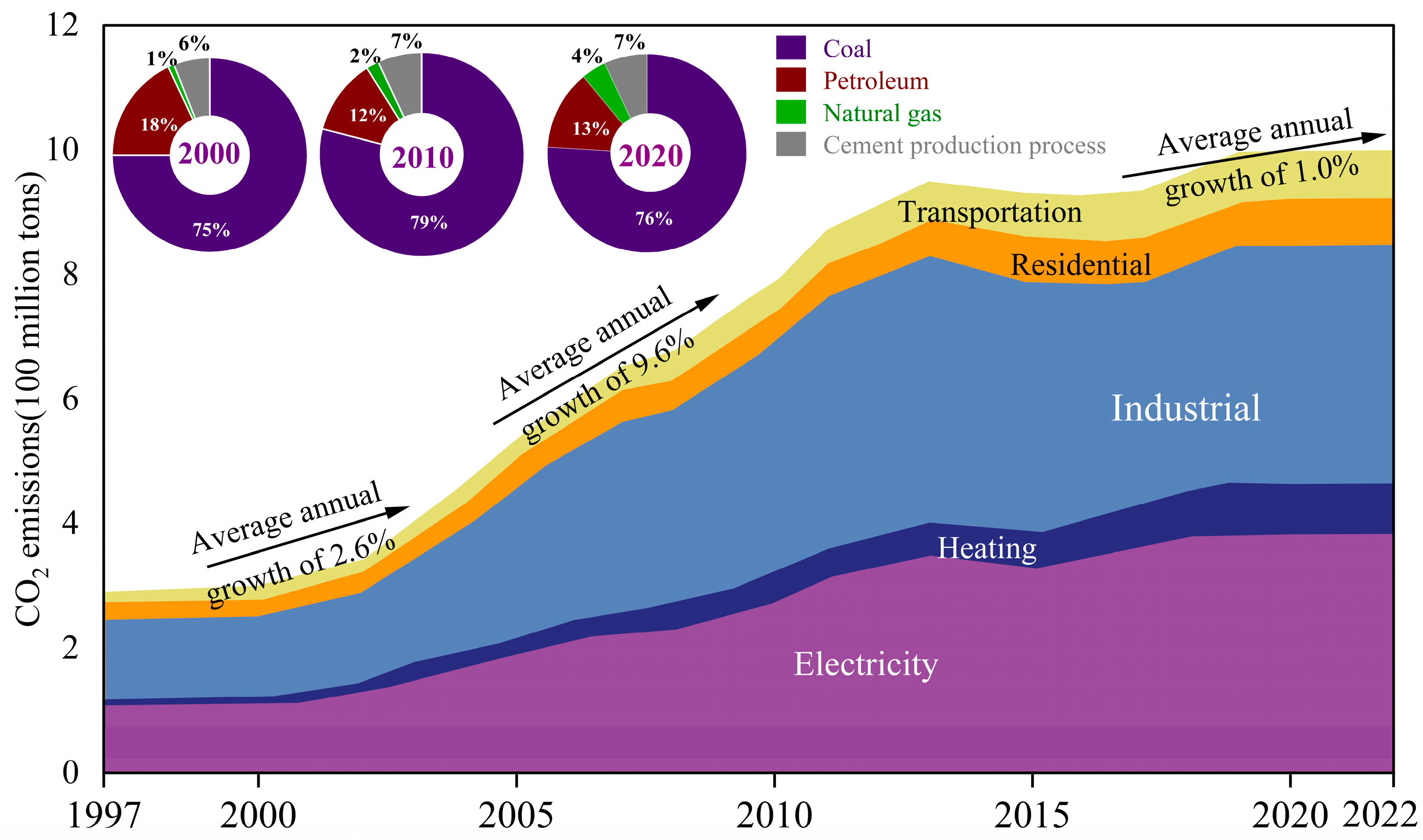
Figure 1. Carbon emission data over the years (data source from [17]).
Energies 17 02672 g001
Figure 2. Schematic diagram of goaf with sufficient underground space for storing CO2.
Energies 17 02672 g002
Figure 3. CO2 storage characteristics (modified after [32]): (a) conversion diagram of CO2 gas–liquid phase; (b) schematic diagram of CO2 density variations with depth.
Energies 17 02672 g003
Figure 4. Schematic diagram of CO2 trap storage in goaf.
Energies 17 02672 g004
Figure 5. The hierarchical structure diagram.
Energies 17 02672 g005
Figure 6. Column diagram of strata in Yaojie mining area.
Energies 17 02672 g006
Table 1. Classification of CO2 geological storage stages in goaf of coal.
StageObjectEvaluation
ObjectiveMethodScalePotential
Regional gradeSecondary structural units in sedimentary basinsCalculate the predicted storage potential and evaluate the geological storage prospect areaData collection, remote sensing interpretation, field research, and comprehensive research1:50,000–1:200,000Predicting
Mine field gradeThird structural units in sedimentary basinsSelect the target area for geological storage within the structural trapData collection, remote sensing interpretation, field research, and comprehensive research1:10,000–1:50,000Control
Mine gradeCoal goafProvide a basis for the engineering design of favorable storage goafRemote sensing interpretation, field research, comprehensive research, sample collection and testing, numerical simulation1:1000–1:10,000Basic
Perfusion gradeUnit in the goafConstruction design and environmental monitoringComprehensive research, sample collection and testing, numerical simulation1:200–1:1000Sealing
Table 2. Comparison of element importance and quantitative scaling relationship.
SameSlightlyObviousNotableVeryExtraordinary
Quota0.50.60.70.80.91
Table 3. Grading evaluation table of the regional geological stability index.
SuitableAbove AverageAverageBelow Average
Tectonic settingCraton BasinInland Rift ValleyPassive margin basinStrike slip fault basin
VolcanoNoLow incidence areaVolcano occurrence areaVolcanic prone areas
Distance from the volcanic zone (km)>250100–25025–100<25
EarthquakeNoLow incidence areaEarthquake occurrence areaEarthquake prone areas
Historical earthquakesEnclosed area<44–6>4
Peak ground acceleration (g)<0.050.05–0.10.1–0.2>0.2
FaultNoCracks, no faultsMudstone filling faultDeep faults, large cracks
Active faultsNo active faults within 25 kmNo active faults within 25 km, with unclear faults No active faults within 10 kmNo active faults within 10 km, with unclear faults
Table 4. Grading evaluation table of sedimentary basin properties.
SuitableAbove AverageAverageBelow Average
Mechanical environmentCompressiveCompression torsionTorsionTension–torsion, tension
Geothermal flow value (mW/m2)<3030–5050–90>90
Ground temperature (°C)<11–22–4>4
Table 5. Grading evaluation table of the sealing of cap rock.
SuitableAbove AverageAverageBelow Average
LithologyMudstone, marlShale, sandy mudstoneArgillaceous siltstoneSandstone
Single layer thickness>20 m10–20 m2.5–10 m<2.5 m
Accumulated thickness>300 m100–300 m20–100 m<20 m
ContinuityRegional distributionContinuity of coalfieldAlmost continuouslyUncontinual
Spatial combinationMany21No
Mining technologyBackfillMainly for backfillMainly for stope cavingStope caving
Table 6. Grading evaluation table of hydrogeological conditions.
SuitableAbove AverageAverageBelow Average
Groundwater volumeNoA little waterWater remains unchangedLarge
Salinity (g/L)30–5010–300–10>50
Temperature (°C)<22–33–4>4
Table 7. Grading evaluation table of storage potential factors.
SuitableAbove AverageAverageBelow Average
Storage area (km2)>5010–501–10<1
Storage capacity (104t)>500100–50010–100<10
Exploration degreeExplorationPart of explorationGeneral explorationGeneral investigation
Temperature (°C)<−2−2–1010–20>20
Geothermal gradient (°C/100 m)<22–33–4>4
Table 8. Grading evaluation table of the economic factors.
SuitableAbove AverageAverageBelow Average
Carbon source scale (104t/a)>5025–5010–25<10
Storage capacity per Unit area (104t/km2)>15050–15010–50<10
Carbon source distance (km)<1010–5050–100>100
Distance from residential areas (m)>12001000–1200800–1000<800
Land use statusDeserts or unused landGrassland and forest landCultivated landResidential areas
Transportation modePipelineShort-distance roadRoadRailway
LandformDuneHillFlat landMountain
Terrain slope (°)0–55–1010–25>25
Exploration degreeExplorationPart of explorationGeneral explorationGeneral investigation
DataSufficient and reliableSufficient data, generally reliableData and reliability are averageInsufficient
Table 9. Grading evaluation table of environmental protection.
SuitableAbove AverageAverageBelow Average
Population density (/km2)<2525–5050–100>100
Geological-hazard-prone areasNoFewHiddenExist
Adverse geological processesNoFewHiddenExist
Table 10. Weighting values related to the factors that control the suitability of coal goaf for geological CO2 storage.
First-Level Parameter (A)Second-Level Parameter (B)Third-Level Parameter (C)Fourth-Level Parameter (D)
Geological safety factors (A1) [0.45, 0.55]Regional crustal stability (B1) 0.10Tectonic setting (C1) 0.10
Volcano (C2) 0.10Volcano (D1) 0.75
Distance from the volcanic (D2) 0.25
Earthquake (C3) 0.10Earthquake (D3) 0.65
Historical earthquakes (D4) 0.35
Regional fault activity (C4) 0.60Peak ground acceleration (D5) 0.15
Fault (D6) 0.40
Active faults (D7) 0.55
Sedimentary basin properties (B2) 0.15Mechanical environment (C5) 0.60
Geothermal flow value (C6) 0.20
Ground temperature (C7) 0.20
Sealing of the cap rock (B3) [0.60, 0.65]Lithology (C8) 0.30
Cap rock thickness (C9) [0.20, 0.30]Single layer thickness (D8) [0.60, 0.70]
Accumulated thickness (D9) [0.30, 0.40]
Continuity (C10) 0.20
Spatial combination (C11) [0.10, 0.15]
Mining technology (C12) [0.1, 0.2]
Hydrogeological conditions (B4) [0.10, 0.15]Groundwater volume (C13) 0.60
Salinity (C14) 0.10
Temperature (C15) 0.30
Storage potential factors (A2) 0.10Storage area (B5) [0.10, 0.20]
Storage capacity (B6) [0.55, 0.65]
Exploration degree (B7) 0.10
Temperature (B8) 0.05
Geothermal gradient (B9) 0.10
Economic factors (A3) [0.15, 0.25]Carbon source scale (B10) 0.10
Storage capacity per unit (B11) 0.05
Carbon source distance (B12) 0.35
Distance from residential (B13) [0.05, 0.10]
Land use status (B14) [0.05, 0.10]
Transportation mode (B15) 0.10
Landform (B16) 0.05
Terrain slope (B17) 0.05
Exploration degree (B18) 0.10
Data (B19) 0.05
Environmental protection (A4) 0.20Population density (B20) [0.45, 0.60]
Geological hazard-prone (B21) [0.20, 0.45]
Adverse geological processes (B22) 0.10
Disclaimer/Publisher’s Note: The statements, opinions and data contained in all publications are solely those of the individual author(s) and contributor(s) and not of MDPI and/or the editor(s). MDPI and/or the editor(s) disclaim responsibility for any injury to people or property resulting from any ideas, methods, instructions or products referred to in the content.