Abstract
Carbon neutrality has become a global common goal. CCUS, as one of the technologies to achieve carbon neutrality, has received widespread attention from academia and industry. After CO2 enters the formation, under the conditions of formation temperature and pressure, supercritical CO2, formation water, and rock components interact, which directly affects the oil and gas recovery and carbon sequestration efficiency. In this paper, the recent progress on CO2 water–rock interaction was reviewed from three aspects, including (i) the investigation methods of CO2 water–rock interaction; (ii) the variable changes of key minerals, pore structure, and physical properties; and (iii) the nomination of suitable reservoirs for CO2 geological sequestration. The review obtains the following three understandings: (1) Physical simulation and cross-time scale numerical simulation based on formation temperature and pressure conditions are important research methods for CO2 water–rock interaction. High-precision mineral-pore in situ comparison and physical property evolution evaluation are important development directions. (2) Sensitive minerals in CO2 water–rock interaction mainly include dolomite, calcite, anhydrite, feldspar, kaolinite, and chlorite. Due to the differences in simulated formation conditions or geological backgrounds, these minerals generally show the pattern of dissolution or precipitation or dissolution before precipitation. This differential evolution leads to complex changes in pore structure and physical properties. (3) To select the suitable reservoir for sequestration, it is necessary to confirm the sequestration potential of the reservoir and the later sequestration capacity, and then select the appropriate layer and well location to start CO2 injection. At the same time, these processes can be optimized by CO2 water–rock interaction research. This review aims to provide scientific guidance and technical support for shale oil recovery and carbon sequestration by introducing the mechanism of CO2 water–rock interaction, expounding the changes of key minerals, pore structure, and physical properties, and summarizing the sequestration scheme.
1. Introduction
In recent years, carbon neutrality has attracted the attention of countries all over the world. Twenty-eight countries around the world have achieved or committed to carbon neutrality targets, including China, which will also strive for peak carbon dioxide emissions by 2030 and carbon neutrality by 2060 [1,2]. Carbon dioxide capture, utilization, and storage (CCUS) is a key area of concern in many carbon neutralization technologies. From 2000 to 2021, a total of 95 countries participated in CCUS research; the number of publications in the CCUS field ranged from 12 articles per year in 2000 to 1084 articles per year in 2021 [3]. From the perspective of the development of thematic research, the issue of sequestration has always been one of the research topics of CCUS.
The types of sequestration are mainly divided into geological sequestration, mineral carbonation, and marine sequestration. Scientific research shows that among the three types of sequestration, CO2 geological sequestration technology is one of the best choices for large-scale and low-cost carbon removal of CO2 in the world [4,5]. As a key mechanism restricting CO2 geological sequestration, the CO2 water–rock interaction has become the focus of widespread attention in academia and industry [6]. CO2 water–rock interaction mainly refers to a series of physical and chemical reactions between CO2 and formation water, oil, natural gas, and mineral components under formation temperature and pressure conditions during CO2 flow-through, sequestration, and later diffusion. After CO2 is injected into the formation, CO2 first dissolves with formation water to form a weak acid fluid. The acid fluid causes the dissolution of unstable minerals and cements, accompanied by the precipitation of secondary minerals, particles, and precipitation migration to plug the pores, affecting the mineralogical characteristics, pore structure characteristics, physical properties, and other properties of the reservoir, and there is a risk of CO2 leakage by inducing fractures or reactivating faults. Currently, most of the international research on CO2 water–rock interaction focuses on the mechanism of the mineral reaction, the change of porosity and physical properties, and the evaluation of reservoir sequestration potential based on CO2 water–rock interaction, but there is no unified evaluation standard established. This paper introduces the principle, research methods, and cognitions of the CO2 water–rock interaction, explores the types of reservoirs suitable for carbon sequestration, analyzes the existing problems, and puts forward the suggestion for the next step, to provide scientific guidance for the follow-up study of CO2 water–rock interaction.
2. Research Method of CO2 Water–Rock Interaction
Studying the influence of CO2 water–rock interaction is the basis and premise for the evaluation of the potential for CO2 sequestration in reservoirs. Observation and research on how CO2 reacts with minerals in the reservoir and affects the development of pores and physical properties after entering the reservoir has always been a major issue [7]. In terms of the number of studies, about 28,534 results were retrieved in Seeking Knowledge on the topic of CCUS-related technologies from 2003 to April 2024 (Figure 1a). The CO2 water–rock interaction has widely existed in various industrial activities of CCUS [8]. There are few articles on its comprehensive evaluation. From the keywords of articles related to the CO2 water–rock interaction, it is found that most articles link CO2 water–rock interaction with carbon sequestration (Figure 1b). This shows that CO2 water–rock interaction is an important factor affecting the sequestration effect.
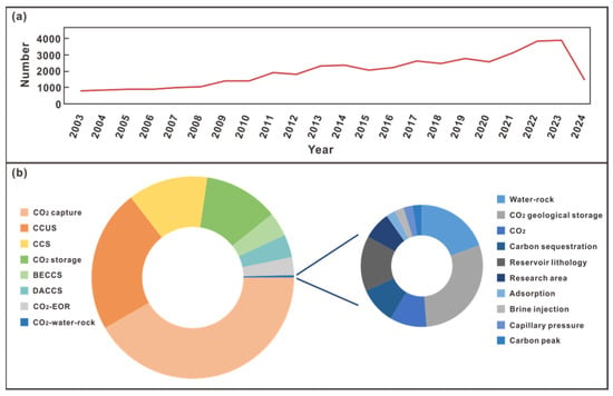
Figure 1.
(a) Trends in the number of articles on CCUS-related topics from 2003 to 2024; (b) b left: the proportion of each topic in the literature published in 2020–2024; b right: the proportion of each keyword in the theme of carbon dioxide water–rock interaction. All data are from Seeking Knowledge (https://www.xunzhi.info/paper/advsearch.py, accessed on 1 August 2024).
Currently, the main research methods are divided into physical simulation methods and numerical simulation methods. The physical simulation generally refers to the temperature and pressure environment of the formation conditions and designs physical simulation experiments to simulate a series of effects on the reservoir and caprock during the initial CO2 injection into the formation and the later CO2 sequestration process. The physical simulation is generally the following two experimental methods: (1) CO2 water–rock sequestration experiment under formation conditions; (2) CO2 water–rock flow-through experiment under formation conditions.
2.1. Advances in Physical Simulation Experiments Research Methods
Physical simulation experiment research methods currently have the following situations: (1) Most of the physical simulation experiments will choose to use a gripper in a high-temperature and high-pressure reactor for experiments. For example, Yuan Zhou et al. [9] conducted a flow-through simulation experiment on samples from Changqing Oilfield. The average diameter of the core is 25.24 mm, the average length is 75.44 mm, and the average mass is 72.04 g. Another CO2 flow-through simulation experiment was performed on samples from the southern Songliao Basin by Zhi Chao et al. [8]. The samples were processed into columnar samples with a diameter of 2.5 cm, and three columnar samples were combined into a ‘combined specimen’ with a total length of 16.1 cm. However, the use of a gripper will make the selected sample specifications limited to the size of the gripper. The specifications of the experimental samples are not diverse enough, and the resolution of the analysis results is not high-resolution and comprehensive. Although the change of rock samples under the closest formation conditions can be observed intuitively by using the gripper, the changes of sensitive minerals, pore structure, and physical properties in the samples cannot be observed. To improve this, one can choose to improve the gripper, use more diverse specifications of the sample, or use a variety of specifications of the sample, to observe the micro-level changes of the sample. (2) In fact, some scholars have carried out experiments on combined samples before this. Guijie Sang [10] prepared the samples into three forms: powder samples for XRD analysis (300 mesh), four flakes for SANS experiments (thickness: 1 mm), and two cores for ultrasonic testing (diameter: 1 inch); Bing Wei [11] used an average core diameter of 25 mm, a length of 8 mm, and granular samples with a grain size of 0.85 mm to 1.18 mm in the sequestration physical simulation experiment. These simulations can compare the analysis before and after the experiment, but these results lack the analysis of the experimental process. There are a few experiments that record the experimental changes at a fixed time point, but the results cannot be completely matched with the pre-experimental analysis results (Table 1). Therefore, the detection points of the simulation experiment need to be increased to record the changes in the experimental process, which can reflect the change more comprehensively. (3) At present, many simulation experiments record the changes in the experimental process. Although there are obvious changes at a fixed time point, few of them can do in situ comparative analysis. In Table 1, only the analysis experiments of Wu [12] and Zhao [13] can take into account both the recording of the experimental process and the in situ comparative analysis.

Table 1.
Advances in laboratory experiments [12,13,14,15,16,17,18,19,20].
For the above three cases, the experiments by Wu [12] and Zhao [13] exactly solved these cases. They designed a combination of more specifications of samples for experiments, so that samples of different specifications can be reacted under the same reaction conditions, which can obtain the maximum number of test results and achieve in-situ experiments. Taking Wu [12] as an example, the rock samples were divided into four specifications for experimental analysis. The two specifications of the plunger samples were subjected to nuclear magnetic resonance (NMR) and micro-CT experimental analysis; 1 cm × 1 cm × 1 cm cubes were for SEM, and QEMSCAN analysis and 200 mesh powder samples were for X-diffraction experimental analysis as well as nitrogen adsorption experiments. During the experiment, the formation water solution in the experiment was examined by an ion solution (Figure 2). This experimental method can completely record the changes of the fixed time points in the whole experimental process of the sample, and high-precision in situ comparison of the same mineral and pore before and after the experiment can be carried out, which was not achieved in previous studies (Figure 3). Unlike the previous physical simulation where the samples could be observed in real time at high temperatures and pressures, the samples were taken out at normal temperature and pressure. The current high-temperature and high-pressure flow-through, sequestration experiments, and seepage experiments have limitations. It is difficult to observe the complete process of dissolution, precipitation, and mineral migration in the CO2 water–rock interaction, and it is also impossible to effectively predict the change of pore structure and permeability in the reaction process, and some high-resolution techniques are needed to observe these pore-scale changes. In the future study of CO2 water–rock interaction, laboratory visualization experiments can be deeply combined to provide detailed data for simulation experiments of each process.
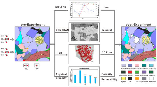
Figure 2.
Research process diagram. ICP-AES analysis was performed on the reaction liquid sample, and X-ray diffraction (XRD) experimental analysis, SEM, QEMSCAN, micro-CT, and nuclear magnetic resonance analysis (NMR) were performed on the rock sample. The changes of reservoir before and after the experiment were evaluated comprehensively from the aspects of liquid, mineral, pore structure, and physical properties.
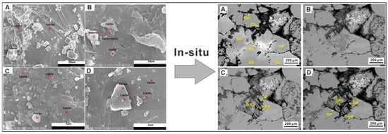
Figure 3.
Kaisar Ahmat (2022) recorded the changes of calcite before and after the experiment. (A) Case A before the experiment; (B) Case A after the experiment; (C) Case B before the experiment; (D) Case B after the experiment [21]; Zhao (2022) recorded the changes of minerals and pores at the same position during the experiment. (A1) The initial sample; (B1) the sample after 24 h, with no observable dissolution; (C1) holes formed due to dissolution after 72 h; (D1) after 192 h, the dissolution pores became larger [13].
2.2. Advance in Numerical Simulation Experimental Research Methods
For numerical simulation, there are two ways for different research objectives. The first one is to simulate the experimental results based on the existing physical simulation experiment results, to restore the changes of key minerals, pore structure, and physical properties in the physical simulation process, and to explore whether there are key phenomena in the physical simulation process. At the same time, it also simulates the interaction rate of minerals and the degree of the consequent changes in CO2 concentration, etc. Senyou An [22] developed a pore-scale volumetric lattice–Boltzmann model coupled with the geochemical simulator, PhreeqcRM. This model was successfully verified with two sets of pore-scale experiments. Such simulation can not only confirm the credibility of the physical simulation experiment, but also restore the details that have not been paid attention to in the physical simulation experiment, confirm the theoretical conjecture, and carry out simulations of other parameters based on the model. However, numerical simulation can only be applied when the accuracy of the model is high with small relative error [23]. Multi-type models can be established to adapt to the whole process in the future. For different interaction fluids, the simulation of interaction rate and secondary minerals of CO2 with different minerals under different temperature and pressure conditions can be carried out to improve the accuracy of relevant parameters.
The second one is to simulate medium and long-term data for the results of short-term physical simulation experiments to simulate the effect of medium and long-term sequestration, mainly focusing on the CO2 charging time and rate, charging mode, as well as the influence of the changes of various parameters on the sequestration efficiency. Gao [24] studied the effect of CO2 injection on caprocks and reservoirs during geological sequestration, first simulated the CO2–saline water–rock interaction under real formation conditions, and then modeled the geological sequestration with a process of 500 years by CMG-GEM software. By changing the CO2 injection time parameters, it is judged whether CO2 is migratory sequestration, dissolution sequestration, or mineralization sequestration. E. Ghoodjani [25] used the data simulator combined with the analysis model to analyze the sensitivity of the CO2 injection rate, and to determine the more suitable injection rate for different reservoirs. Accurate medium and long-term simulation can guide CO2 sequestration and CO2-EOR strategies to assess the sequestration potential, but it also requires a large amount of data as support.
3. Mineral Evolution
After CO2 is injected into the ground and in contact with the formation water, some carbon dioxide will dissolve in the water, forming HCO3− and CO32−, resulting in the formation water being weakly acidic. In an acidic environment, unstable minerals will dissolve and release some Ca2+, Mg2+, etc. Then, it interacts with HCO3− and CO32− to form stable carbonate minerals. Therefore, there are both dissolution and precipitation phenomena in the progress of the CO2 water–rock interaction (Figure 4).
CO2(g) + H2O⇌H2CO3(aq),
H2CO3⇌HCO3− + H+,
HCO3−⇌H+ + CO32−,
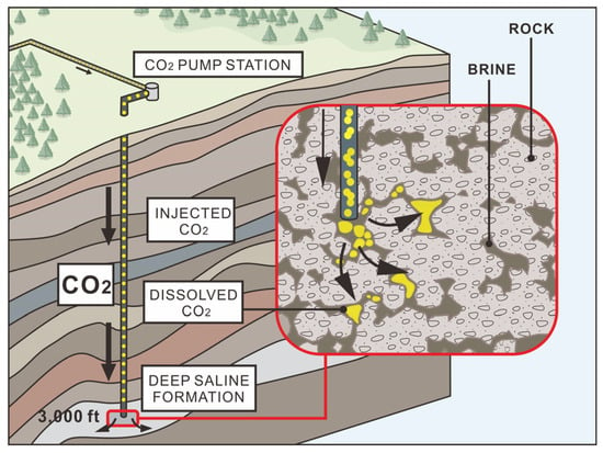
Figure 4.
CO2 water–rock interaction diagram (revising from [26]). The black arrow represents the direction of CO2 flow.
The CO2 water–rock interaction characteristics of different minerals are different; some minerals will be dissolved in the acidic solution, while some minerals will be precipitated in the long sequestration process. There are also unstable mineral structures that are eroded and destroyed, resulting in mineral migration. These factors will affect the porosity and permeability of the reservoir, and these unclear factors are not favorable to the choice of CO2 sequestration reservoir. However, due to the different experimental schemes, reservoir types, and other conditions, many scholars cannot reach a more unified conclusion.
Minerals can be divided into clay minerals and non-clay minerals. There are three main trends: dissolution, precipitation, and dissolution before precipitation. Among them, non-clay minerals are mainly dolomite, calcite, anhydrite, and feldspar, and clay minerals are mainly kaolinite and chlorite. As carbonate minerals, the changes of dolomite and calcite are particularly obvious in the CO2 water–rock interaction. Kaisar Ahmat et al. [21] found that when the content of dolomite was more than 85%, it was dissolved under acidic conditions when studying mixed rock samples in the Tarim Basin. When Sebastian Fischer et al. [27] studied the sandstone samples of the Ketzin formation, he found that when the content of potassium feldspar was 5–25%, the samples would precipitate dolomite crystals at the cost of plagioclase dissolution. At this time, the change trend of dolomite was mainly precipitation (Figure 5a). Calcite reaction is more sensitive to temperature and will dominate precipitation at higher temperatures [18] and dissolution at lower temperatures [28]. In addition, there will be samples with high dolomite content. Calcite will be dissolved first, and then a high content of dolomite will be converted into calcite precipitation (Figure 5b). The temperature peak of the maximum solubility of calcite may occur between 135 °C and 185 °C; when the experimental temperature exceeds this temperature, the solubility of calcite will decrease, thus affecting the water–rock interaction of CO2 and minerals [29]. Gunter et al. [30] also pointed out that aluminosilicates containing calcium and magnesium (or other divalent cations) are the greatest potential minerals to improve the sequestration capacity of CO2 because they can combine with H+ to form carbonate minerals, kaolinite, and quartz while dissolving.
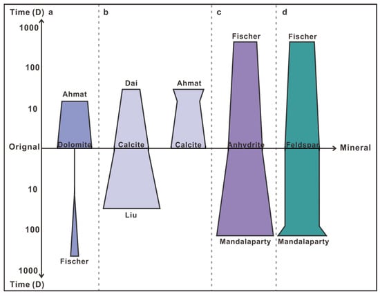
Figure 5.
Schematic diagram of trends in four minerals: dolomite, calcite, hard gypsum, and feldspar [18,21,27,28,31]. (a) dolomite trends in interaction; (b) calcite trends in interaction; (c) anhydrite trends in interaction; (d) feldspar trends in interaction.
Sebastian Fischer, in his study of sandstone formations in Stuttgart, found that when the initial concentration of calcium and sulfate in synthetic brine was lower than that of formation fluid, anhydrite dissolved to increase the ion concentration in brine [27]. Mandalaparty conducted a study on the reaction of self-made diamictite rock samples with CO2 + SO2 and found that anhydrite crystals rapidly nucleate and grow [31] (Figure 5c). In the Stuttgart sandstone formation, to balance the salt water concentration and the formation concentration, some feldspar will be converted into calcite, and the samples with high feldspar content will be preferentially dissolved, and the surface is accompanied by corrosion texture [27]; in the samples with high content of diamictite rock quartz, quartz will first dissolve to provide ions, while the precipitation speed of feldspar is faster than that of quartz in the later stage of precipitation, and, finally, feldspar is precipitated [31,32] (Figure 5d). Zhang et al.’s experiment using CO2 hydrolysis solution in the sandstone of the Rio Bonito formation in southern Brazil showed that feldspar and calcite would dissolve, and silicate minerals might also precipitate. Due to the different types of reservoirs, the degree of dissolution was also different [33,34]. It can be seen that the changes in key minerals are different, and the experimental conditions are important influencing factors, but the specific rules still need to be explored.
4. Pore Structure and Physical Property Changes
4.1. Pore Structure
The previous evaluation of pore structure is mainly aimed at the average pore size and fracture, which together affect the change of reservoir physical properties. After CO2 is injected into the formation, the early dissolution will lead to the increase of dissolution pores, which will expose more mineral surfaces. With the extension of reaction time, the average pore size will gradually increase [28,35,36,37,38]; in some samples with high content of carbonate minerals, the average pore size decreases due to the expansion effect and precipitation [39] (Figure 6). Park et al. investigated the effect of CO2 sequestration on the porosity of caprock in Janggi Basin, South Korea, through physical simulation experiments. After the experiment, they observed that the dissolution of primary minerals led to an increase in caprock porosity. The porosity of the samples before and after the experiment was tested by pressure mercury porosity measurement and CT scanning. Respectively, the porosity increased from 14.9% to 18.7% and from 15.1% to 20.7%, and the dissolution of primary calcite was the cause of the porosity change [40].
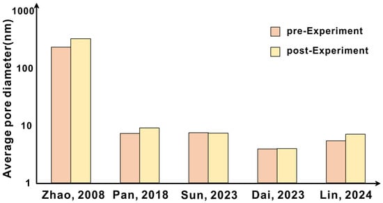
Figure 6.
Trend of average pore diameter before and after the experiment [28,35,37,38,39].
For fractures, after the reaction of SC-CO2, saline, and samples, the mechanical properties of the samples are reduced, and SC-CO2 penetrates the pore dissolution minerals, leading to an increase in the number of hydraulic fractures, which expands the instability of fracture and increases the complexity of the fracture shapes [41]; it also reduces the mechanical strength of the sample, promotes the occurrence of fracture, and activates pre-existing random directional microfractures, which increases the volume of main/microfractures [42], but diagenesis can also hinder fracture growth [43]. These characteristics have an impact on long-term sequestration security.
4.2. Physical Property
The predecessors’ cognition of the evolution of physical properties also has varied views with different experimental settings. In the flow-through experiments, the CO2 injection rate is an important factor. The CO2 injection rate not only affects the CO2 water–rock reaction rate, but also promotes mineral migration [12,44] (Figure 7). During the experiment, the migration of fine detached particles caused by upstream dissolution will block the downstream microfractures, and the physical properties decrease [45,46,47]. If the released particles are washed away, the alteration layer is detached, and the physical properties increase [48,49]; if the released particles are redeposited in the fracture, the pore size of the microfracture is significantly reduced and the physical properties are reduced [50,51]. For example, I. M. Mohamed conducted a flow-through experiment with homogeneous carbonate rocks and found that the permeability of the core is the same along the length of the core. The core is cut into three pieces, regardless of the temperature and injection rate; the first core is increased compared with the original permeability due to calcite dissolution, and the latter two cores begin to show a decreased permeability because of mineral migration. At different injection rates, the overall permeability of the core also changes differently. When the injection rate is 5 cm3/min, the permeability increases; when the injection rate is 2 cm3/min, the permeability decreases [14]. However, there are also different opinions. Loquot [52] found that regardless of the injection rate and the type of saline, the permeability increased in the experiment of Heletz. In the sequestration experiment, the change of physical properties is closely related to the temperature and pressure conditions and the type of reservoir. The corrosion of minerals can weaken and expand the edge of dissolved pores and increase the physical properties [42,53] (Figure 7). When the mineral expansion effect is stronger than the dissolution effect, the physical properties decrease [39]. With the increase of experimental pressure, the porosity of the sample increases first and then decreases [54]. Different reaction temperatures lead to different degrees of dissolution and precipitation of different minerals, which in turn affects the physical properties [8,55].
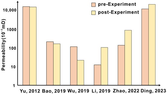
Figure 7.
Trend of permeability before and after the experiment [8,12,13,42,44,53].
5. Selection of Geo-Storage Reservoir
Global CCUS technology is in the research and development stage, and due to various cost, environmental, policy, and other issues, most of the CCUS projects in operation are aimed at the single technical aspect of CCUS, and gradually carry out large-scale CCUS demonstration projects. According to incomplete statistics, China has more than 20 CCUS experimental and demonstration projects under construction and operation, 13 international cooperative research projects, and 17 projects supported by the Chinese government [24,56]. Among them, China’s separate geological utilization and sequestration projects account for about 10%, which is a significant gap compared with developed countries with experience in multiple full-process CCUS technology demonstration projects [57,58] (Table 2); there is still much potential for China’s current carbon sequestration technology and industrial processes.

Table 2.
Summary of global CO2 geo-storage projects [59].
The development of carbon sequestration technology is conducive to CCUS project decision-making. The first is the selection of reservoirs. Generally, the selection of reservoirs mainly focuses on (1) the sedimentary phase type (clastic rock, carbonate rock) and sedimentary environment of the reservoir (Figure 8); (2) sequestration depth, thickness, and three-dimensional geometry and integrity of the reservoir; (3) physical properties and heterogeneity of reservoir [60]. In this regard, Bachu et al. [61], Shen Pingping et al. [62], and Diao Yujie et al. [63] have successively proposed grading standards for CO2 geological reservoir suitability evaluation (Table 3). Generally, the sequestration potential of the reservoir can be judged according to the existing physical simulation and numerical simulation experiments, to further optimize the reservoir suitable for sequestration. For example, CO2 geological sequestration in deep saline aquifers is generally carried out in sandstone and carbonate reservoirs. CO2 will be stored in small spaces between the rock particles of these porous rocks. These spaces are not only conducive to the injection and penetration of CO2, but also greatly improve the ability to store CO2 [64,65].
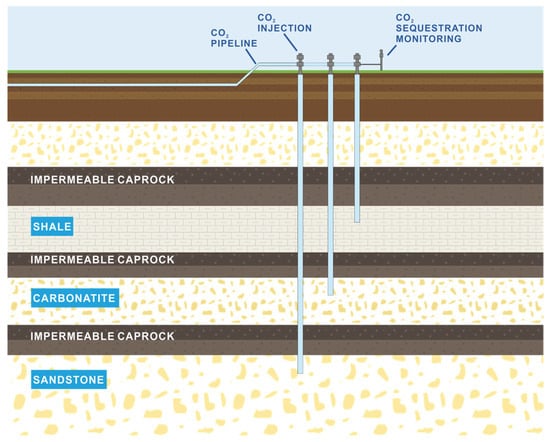
Figure 8.
Reservoir lithofacies diagram (revising from [66]). In Table 2, the reservoir lithofacies of more than half of projects are sandstone.

Table 3.
Reservoir stability assessment indexes and grading standards in target scale stages [63].
When selecting a reservoir suitable for sequestration in the CCUS project, the program should not only pay attention to whether the reservoir storing CO2 is suitable, but also pay attention to the selection of caprock, to avoid CO2 leakage in the later sequestration process. Generally speaking, the thicker the caprock is, the more favorable it is for sequestration [67]. The common caprock lithology is divided into three categories: argillaceous rock accounts for about 70%, gypsum-salt rock accounts for about 20%, and carbonate rock and igneous rock account for about 10%; especially gypsum-salt rock and shale are excellent caprock lithology [68,69]. The caprock lithology, caprock distribution characteristics, caprock thickness, rock mechanical properties, and sealing pressure are the main factors affecting caprock sealing. The sealing ability of caprocks with different lithology shows gypsum-salt rock > mudstone > carbonate rock > argillaceous siltstone [70]. Many projects will choose to carry out laboratory experiments to evaluate and use laboratory data directly. However, due to the large difference between laboratory conditions and actual conditions, such as medium properties, interfacial tension, and permeability, if they are directly used for evaluation without correction, there will be a large error between the experimental value and the true value of the evaluation parameters of caprock sealing. This is also a point that needs to be paid attention to before the actual use of laboratory data in the project.
The success of the CCUS project depends not only on the reservoir and caprock, including the location of the injection well, the selection of the injection rate, and the selection of the injection method, which will also affect the effect of the sequestration. In numerical simulations, especially for medium and long-term numerical simulation, compared with short-term simulation, the injection rate of CO2 is less affected by the characteristics of CO2 itself, reservoir rock, resident fluid, and injection process [71]. To enhance the sequestration effect of some projects, the injection point will be selected in the middle and lower part, which can increase the migration distance of CO2 in the reservoir, and to a certain extent, it can also enhance the capture effect of residual gas [72]. The injection method will also adopt the method of alternating water and gas to improve the solubility of CO2 and increase the total sequestration capacity. After the physical simulation experiment of CO2–underground fluid–rock, Zhang Minglong et al. [73] studied the dynamic changes of formation fluid properties, fluid components, seepage characteristics, rock pore structure, and other parameters after CO2 gas was injected into the formation. On this basis, the injection parameters and injection methods of the actual injection wells were adjusted. The initial gas continuous injection of the two wells was changed to water–gas alternating injection with a water–gas ratio of 1.5:1 and CO2 foam injection with a water–gas ratio of 1:1. The daily oil production increased from 5.6 t to 15 t, and the CO2 sequestration effect was greatly improved. Similarly, Rashid Mohamed Mkemai and Gong Bin conducted a numerical simulation of the Shenhua CCS project, using LandSim6 3D commercial modeling to analyze the parameters of injection rates, bottom hole flow pressure, and cumulative amount of stored CO2 and established the optimal CO2 injection scheme that will enhance CO2 storage without endangering the safety of the caprock and the formation above it [74]. After the sequestration of CO2, it should be monitored. Long-term stability is related to the behavior of CO2 and the reservoir over longer time scales (from years to centuries or even millennia). This is related to the gradual migration of CO2 in the reservoir, the continuous interaction between CO2, reservoir fluids, and minerals, and the long-term risks associated with CO2 corrosion of the wellbore leading to leakage or any other potential ways. [75,76]. Monitoring CCUS projects is not only for on-site safety issues, but also to avoid irreversible impacts on reservoirs and the environment. For example, CO2 leakage will affect the ecological environment of soil and interfere with plant growth, pollute groundwater, and affect human health and may cause earthquakes [77]. At the same time, according to the successful implementation of CCUS projects in the past, it is also important to evaluate the economic benefits (transportation cost, pipeline cost, and commercial value) and deal with the policy issues; otherwise, it will also affect the rapid development of CCUS projects.
The processes of confirming the sequestration potential, selecting the sequestration reservoirs, and the well location, injection rate, methods, and temperature of the injection well during sequestration are all related to the CO2 water–rock interaction. A deep understanding of the CO2 water–rock interaction mechanism can provide scientific and technical guidance for carbon sequestration, which is conducive to improve carbon sequestration technology.
6. Conclusions
This paper reviews the research methods, cognition, and reservoir selection of CO2 water–rock interaction. (1) For the two research methods of physical simulation and cross-time scale numerical simulation based on formation temperature and pressure conditions, high-precision mineral-pore in situ comparison and physical property evolution evaluation are important development directions, which can improve the accuracy of physical simulation experiment data and lay a good foundation for numerical simulation. At the same time, the development of numerical simulation requires not only a large amount of experimental data, but also field data for feedback, corresponding to the improved model, so that it can predict more accurately, so as to avoid possible problems and improve CO2 sequestration efficiency. (2) There is no uniform standard for the main factors affecting the changes of minerals, pore structure, and physical properties in CO2 water–rock interaction. Formation conditions and geological background are important factors affecting mineral changes, and generally carbonate minerals react most obviously. The precipitation or dissolution of minerals affects the different changes of pore structure and physical properties. Mineral dissolution may lead to the increase of average pore diameter or the development of fractures, and mineral precipitation or expansion may also lead to the decrease of average pore diameter or the blockage of original fractures, and it also involves the expansion effect of some clay minerals. The reaction rate and migration of minerals are also the factors affecting the change of physical properties. (3) The study of CO2 water–rock interaction is helpful to improve the effect of carbon sequestration. It is not only beneficial to evaluate the potential of carbon sequestration, but also can improve the efficiency of carbon sequestration and optimize the CCUS scheme from the aspects of CO2 injection method, rate, and duration.
Author Contributions
Conceptualization, S.W. and C.W.; writing—review and editing, S.W. and C.W.; visualization, Y.S. and X.L. All authors have read and agreed to the published version of the manuscript.
Funding
This research was funded by the National Natural Science Foundation project (grant nos. 42072187), and the Major Science and Technology Project of China National Petroleum Corporation (grant no. 2021DQ-0405).
Data Availability Statement
All relevant data are within the paper.
Conflicts of Interest
C.W., S.W. and X.L. were employed by China National Petroleum Corporation. The remaining authors declare that the research was conducted in the absence of any commercial or financial relationships that could be construed as a potential conflict of interest. The authors declare that this study received funding from China National Petroleum Corporation. The funder was not involved in the study design, collection, analysis, interpretation of data, the writing of this article or the decision to submit it for publication.
References
- Li, Y. Academician of the Chinese Academy of Sciences Ding Zhongli: To achieve carbon neutrality requires ‘three-end force’. Beijing Dly. 2021, T01. [Google Scholar] [CrossRef]
- Zou, C.; Xiong, B.; Xue, H.; Zheng, D.; Ge, Z.; Wang, Y.; Jiang, L.; Pan, S.; Wu, S. The role of new energy in carbon neutral. Pet. Explor. Dev. 2021, 48, 411–420. [Google Scholar] [CrossRef]
- Qian, Y.; Cao, X. Development trend analysis of CCUS research based on bibliometrics. Ind. Saf. Environ. Prot. 2023, 49, 97–101+106. [Google Scholar]
- Lu, P.; Bai, Y.; Liu, W.; Chen, X.; Zheng, H.; Liu, J.; Chen, Y.; Gao, J. Optimization of favorable areas for carbon dioxide geological storage in Majiagou Formation in Ordos Basin. Geol. Rev. 2021, 67, 816–827. [Google Scholar] [CrossRef]
- Mac Dowell, N.; Fennell, P.S.; Shah, N.; Maitland, G.C. The role of CO2 capture and utilization in mitigating climate change. Nat. Clim. Chang. 2017, 7, 243–249. [Google Scholar] [CrossRef]
- Garcia, S.; Kaminska, S.; Maroto-Valer, M.M. Underground carbon dioxide storage in saline formations. Proc. Inst. Civ. Eng.-Waste Resour. Manag. 2010, 163, 77–88. [Google Scholar] [CrossRef]
- Kim, K.; Kim, D.; Na, Y.; Song, Y.; Wang, J. A review of carbon mineralization mechanism during geological CO2 storage. Heliyon 2023, 9, e23135. [Google Scholar] [CrossRef] [PubMed]
- Yu, Z.Y.; Li, S.Y. An experimental study on water-rock interaction during water flooding in formations saturated with CO2. Acta Petrolei Sinica. 2012, 33, 1032–1042. [Google Scholar]
- Yuan, Z.; Liao, X.; Zhang, K.; Zhao, X.; Chen, Z. The effect of inorganic salt precipitation on oil recovery during v flooding: A case study of Chang 8 block in Changqing oilfield, NW China. Pet. Explor. Dev. 2021, 48, 379–385. [Google Scholar] [CrossRef]
- Sang, G.; Liu, S. Carbonate Caprock-Brine-CO2 Interaction: Alteration of Hydromechanical Properties. In Proceedings of the SPE Annual Technical Conference and Exhibition, Virtual, 27 October 2020; p. D022S061R041. [Google Scholar]
- Wei, B.; Zhang, X.; Liu, J.; Xu, X.; Pu, W.; Bai, M. Adsorptive behaviors of supercritical CO2 in tight porous media and triggered chemical reactions with rock minerals during CO2-EOR and -sequestration. Chem. Eng. J. 2020, 381, 122577. [Google Scholar] [CrossRef]
- Wu, S.; Zou, C.; Ma, D.; Zhai, X.; Yu, H.; Yu, Z. Reservoir property changes during CO2-brine flow-through experiments in tight sandstone: Implications for CO2 enhanced oil recovery in the Triassic Chang 7 Member tight sandstone, Ordos Basin, China. J. Asian Earth Sci. 2019, 179, 200–210. [Google Scholar] [CrossRef]
- Zhao, Y.; Wu, S.; Chen, Y.; Yu, C.; Yu, Z.; Hua, G.; Guan, M.; Lin, M.; Yu, X. CO2-Water-Rock Interaction and Pore Structure Evolution of the Tight Sandstones of the Quantou Formation, Songliao Basin. Energies 2022, 15, 9268. [Google Scholar] [CrossRef]
- Mohamed, I.M.; He, J.; Nasr-El-Din, H.A. Permeability Change during CO2 Injection in Carbonate Aquifers: Experimental Study. In Proceedings of the SPE Americas E&P Health, Safety, Security, and Environmental Conference, Houston, TX, USA, 21 March 2011; p. SPE-140979-MS. [Google Scholar]
- Choi, C.-S.; Song, J.-J. Swelling and Mechanical Property Change of Shale and Sandstone in Supercritical CO2. J. Korean Soc. Rock Mech. 2012, 22, 266–275. [Google Scholar] [CrossRef]
- Li, Z.; Guo, J.; Zhang, Y.; Chen, J. High-temperature supercritical CO2 water-rock simulation experiment of sandstone and its geological significance. Nat. Gas Ind. 2015, 35, 31–38. [Google Scholar]
- Olabode, A.O.; Radonjic, M.; Du, H. Diagenetic Fluid Transport in Fractured Shale Using Laboratory Rock/Fluid Interactions Data to Analyze Sealing Potential. In Proceedings of the U.S. Rock Mechanics/Geomechanics Symposium, San Francisco, CA, USA, 25–28 June 2017. [Google Scholar]
- Liu, X. Effect of CO2-Water Reaction on Mineralization and Sequestration Mechanism of Sandstone Reservoir. Master’s Thesis, China University of Geosciences, Beijing, China, 2018. [Google Scholar]
- Li, N.; Jin, Z.; Zhang, S.; Wang, H.; Yang, P.; Zou, Y.; Zhou, T. Micro-mechanical properties of shale due to water/supercritical carbon dioxide-rock interaction. Pet. Explor. Dev. 2023, 50, 872–882. [Google Scholar] [CrossRef]
- Li, Y.; Ma, H.; Li, H.; Leonhard, G.; Tang, Z.; Li, K.; Luo, H. Dissolution of supercritical CO2 on carbonate reservoirs. Pet. Reserv. Eval. Dev. 2023, 13, 288–295+357. [Google Scholar]
- Ahmat, K.; Cheng, J.; Yu, Y.; Zhao, R.; Li, J. CO2-Water-Rock Interactions in Carbonate Formations at the Tazhong Uplift, Tarim Basin, China. Minerals 2022, 12, 635. [Google Scholar] [CrossRef]
- An, S.; Erfani, H.; Hellevang, H.; Niasar, V. Lattice-Boltzmann simulation of dissolution of carbonate rock during CO2-saturated brine injection. Chem. Eng. J. 2020, 408, 127235. [Google Scholar] [CrossRef]
- Ghasemi, M.; Astutik, W.; Alavian, S.A.; Whitson, C.H.; Sigalas, L.; Olsen, D.; Suicmez, V.S. Lab Tests and Modeling of CO2 Injection in Chalk with Fracture-Matrix Transport Mechanisms. In Proceedings of the SPE Europec featured at 78th EAGE Conference and Exhibition, Vienna, Austria, 30 May–2 June 2016. [Google Scholar] [CrossRef]
- Gao, Y. Investigation of CO2-Formation Brine-Rock Reaction of Shenhua Ordos CCS Project. Master’s Thesis, China University of Petroleum, Beijing, China, 2020. [Google Scholar]
- Ghoodjani, E.; Bolouri, S.H. Numerical and Analytical Optimization of Injection Rate During CO2-EOR and -Sequestration Processes. In Proceedings of the Carbon Management Technology Conference, Orlando, FL, USA, 7–9 February 2012. [Google Scholar]
- DOE (US Department of Energy). Fossil Energy Research Benefits. Enhanced Oil Recovery; U.S. Department of Energy, Office of Fossil Energy: Washington, DC, USA, 2012.
- Fischer, S.; Liebscher, A.; Wandrey, M. CO2–brine–rock interaction—First results of long-term exposure experiments at in situ P–T conditions of the Ketzin CO2 reservoir. Geochemistry 2010, 70, 155–164. [Google Scholar] [CrossRef]
- Dai, X.; Wang, M.; Feng, G.; Zheng, S.; Ren, B.; Xu, S. Mineralogical erosion and precipitation characteristics and their effects on adsorption property of shale during scCO2-H2O-shale interaction. J. China Coal Soc. 2023, 48, 2813–2826. [Google Scholar] [CrossRef]
- Meng, F.; Li, C.; Liu, L.; Zhou, B.; Zhao, S.; Wang, L.J.; Yu, Z.C. Experiment of CO2-Saline Water-Calcite Interactions. Geol. Sci. Technol. Inf. 2013, 32, 171–176. [Google Scholar]
- Gunter, W.D.; Perkins, E.H.; McCann, T.J. Aquifer disposal of CO2- rich gases: Reaction design for added capacityl. Energy Convers. Manag. 1993, 34, 941–948. [Google Scholar] [CrossRef]
- Mandalaparty, P.; Deo, M.; Moore, J. CO2 Sequestration: Temperature and Gas Compositional Effects on the Kinetics of Min-eralogical Reactions. In Proceedings of the SPE Annual Technical Conference and Exhibition, New Orleans, LA, USA, 4 October 2009; p. SPE-124909-MS. [Google Scholar]
- Druckenmiller, M.L.; Maroto-Valer, M.M.; Hill, M. Investigation of Carbon Sequestration via Induced Calcite Formation in Natural Gas Well Brine. Energy Fuels 2005, 20, 172–179. [Google Scholar] [CrossRef]
- Zhang, R.; Winterfeld, P.H.; Yin, X.; Xiong, Y.; Wu, Y.S. Sequentially Coupled THMC Model for CO2 Geo-logical Sequestration into a 2D Heterogeneous Saline Aquifer. J. Nat. Gas Sci. Eng. 2015, 27, 579–615. [Google Scholar] [CrossRef]
- Wigand, M.; Carey, J.; Schütt, H.; Spangenberg, E.; Erzinger, J. Geochemical effects of CO2 sequestration in sandstones under simulated in situ conditions of deep saline aquifers. Appl. Geochem. 2008, 23, 2735–2745. [Google Scholar] [CrossRef]
- Pan, Y.; Hui, D.; Luo, P.; Zhang, Y.; Zhang, L.; Sun, L. Influences of subcritical and supercritical CO2 treatment on the pore structure characteristics of marine and terrestrial shales. J. CO2 Util. 2018, 28, 152–167. [Google Scholar] [CrossRef]
- Zhou, L.; Kang, Z. Fractal characterization of pores in shales using NMR: A case study from the lower Cambrian Niutitang formation in the Middle Yangtze Platform, Southwest China. J. Nat. Gas Sci. Eng. 2016, 35, 860–872. [Google Scholar] [CrossRef]
- Lin, H.; Mei, J.; Jia, S.; Huang, J.; Ding, M. Variation characteristics of micro-pore structure of shale after CO2-water interaction. Pet. Geol. Oilfield Dev. Daqing 2024, 43, 86–94. [Google Scholar] [CrossRef]
- Zhao, M. Laboratory and Numerical Simulation Study on CO2 Flooding in Ultra Low Permeability Reservoir. Ph.D. Thesis, Daqing Petroleum Institute, Daqing, China, 2008. [Google Scholar]
- Sun, L.; Wang, H.; Wang, B.; Dang, K.; Shi, M.; Zhang, Y.; Liu, M.; Wu, Y. The Effect of SCCO2 Treatments on the Petrophysical Properties of Continental Shale with Different Mineral Compositions. In Proceedings of the 57th U.S. Rock Mechanics/Geomechanics Symposium, Atlanta, GA, USA, 25 June 2023; p. ARMA-2023-0467. [Google Scholar]
- Park, J.; Choi, B.-Y.; Lee, M.; Yang, M. Porosity changes due to analcime in a basaltic tuff from the Janggi Basin, Korea: Experimental and geochemical modeling study of CO2–water–rock interactions. Environ. Earth Sci. 2021, 80, 81. [Google Scholar] [CrossRef]
- Tian, G.; Wang, H.; Li, G.; Yang, B.; Zhao, C.; Zheng, Y. Experiment Investigation on the Fracture Initiation Characteristics of Shale Saturated with CO2 and Brine. In Proceedings of the 56th U.S. Rock Mechanics/Geomechanics Symposium, Santa Fe, NM, USA, 26 June 2022; p. ARMA-2022-0229. [Google Scholar]
- Li, S.H.; Reginald, S.C.Z. Experimental Study on the Impact of CO2-Brine-Rock Interaction on Rock Properties and Fracture Propagation during Supercritical CO2 Fracturing in Chang-7 Tight Sandstone Formation; American Rock Mechanics Association: Atlanta, GA, USA, 2019. [Google Scholar]
- Major, J.R.; Eichhubl, P.; Dewers, T.A.; Olson, J.E. Effect of CO2–brine–rock interaction on fracture mechanical properties of CO2 reservoirs and seals. Earth Planet. Sci. Lett. 2018, 499, 37–47. [Google Scholar] [CrossRef]
- Bao, H. Research on the Variation of Pore Throat during CO2 Injection in Tight Sandstone Oil Reservoir. Master’s Thesis, Xi’an Shiyou University, Xi’an, China, 2019. [Google Scholar]
- Luhmann, A.J.; Kong, X.Z.; Tutolo, B.M.; Garapati, N.; Bagley, B.C.; Saar, M.O.; Seyfried, W.E. Seyfried, Experimental dissolution of dolomite by CO2-charged brine at 100 °C and 150 bar: Evolution of porosity, permeability, and reactive surface area. Chem. Geol. 2014, 380, 145–160. [Google Scholar] [CrossRef]
- Luquot, L.; Rodriguez, O.; Gouze, P. Experimental Characterization of Porosity Structure and Transport Property Changes in Limestone Undergoing Different Dissolution Regimes. Transp. Porous Media 2014, 101, 507–532. [Google Scholar] [CrossRef]
- Erol, S.; Fowler, S.J.; Nehler, M.; De Boever, E.; Harcouët-Menou, V.; Laenen, B. An Analytical Algorithm of Porosity–Permeability for Porous and Fractured Media: Extension to Reactive Transport Conditions and Fitting via Flow-Through Experiments Within Limestone and Dolomite. Transp. Porous Media 2019, 129, 343–383. [Google Scholar] [CrossRef]
- Deng, H.; Voltolini, M.; Molins, S.; Steefel, C.; DePaolo, D.; Ajo-Franklin, J.; Yang, L. Alteration and Erosion of Rock Matrix Bordering a Carbonate-Rich Shale Fracture. Environ. Sci. Technol. 2017, 51, 8861–8868. [Google Scholar] [CrossRef]
- Deng, H.; Spycher, N. Modeling Reactive Transport Processes in Fractures. Rev. Miner. Geochem. 2019, 85, 49–74. [Google Scholar] [CrossRef]
- Noiriel, C.; Madé, B.; Gouze, P. Impact of coating development on the hydraulic and transport properties in argillaceous limestone fracture. Water Resour. Res. 2007, 43, W09406. [Google Scholar] [CrossRef]
- Ellis, J.; Bazylak, A. Investigation of contact angle heterogeneity on CO2 saturation in brine-filled porous media using 3D pore network models. Energy Convers. Manag. 2013, 68, 253–259. [Google Scholar] [CrossRef]
- Luquot, L.; Gouze, P.; Niemi, A.; Bensabat, J.; Carrera, J. CO2 -rich brine percolation experiments through Heletz reservoir rock samples (Israel): Role of the flow rate and brine composition. Int. J. Greenh. Gas Control. 2016, 48, 44–58. [Google Scholar] [CrossRef]
- Ding, Q.; Wang, J.; Yang, L.; Zhu, D.; Jiang, W.; He, Z. Exploring the role of the structural heterogeneity of fractured carbonate reservoirs in contact with dissolved CO2 based on fracture-water-rock simulation experiments. Appl. Geochem. 2023, 150, 105589. [Google Scholar] [CrossRef]
- Xiao, N.; Li, S.; Lin, M. The Influence of CO2-water-calcite Interactions on Surface Texture and Permeability of the Calcite. Sci. Technol. Eng. 2017, 17, 38–44. [Google Scholar]
- Wu, S.; Yu, C.; Hu, X.; Yu, Z.; Jiang, X. Characterization of mineral and pore evolution under CO2-brine-rock interaction at in-situ conditions. Adv. Geo-Energy Res. 2022, 6, 177–178. [Google Scholar] [CrossRef]
- Cai, B.; Li, Q.; Zhang, X.; Cao, C.; Cao, L.; Chen, W.; Chen, W.; Dong, J.; Fan, J.; Jiang, Y.; et al. Annual Report of China Carbon Dioxide Capture, Utilization and Storage (CCUS) (2021)—Study on CCUS Path in China; Environmental Planning Institute, Ministry of Ecology and Environment, Wuhan Institute of Geomechanics, Chinese Academy of Sciences, China Agenda 21 Management Center: Wuhan, China, 2021. [Google Scholar]
- Zhang, X.; Li, Y.; Ma, Q.; Liu, L. Development of Carbon Capture, Utilization and Storage Technology in China. Strateg. Study CAE 2021, 23, 70–80. [Google Scholar] [CrossRef]
- Deng, Y.; Wang, Y.; Zhao, Y.; Gu, P.; Xiao, J.; Zhou, J.; Li, Z.; Yu, Z.; Peng, P. Carbon dioxide storage in China: Current status, main challenges, and future outlooks. Earth Sci. Front. 2023, 30, 429–439. [Google Scholar]
- Bashir, A.; Ali, M.; Patil, S.; Aljawad, M.S.; Mahmoud, M.; Al-Shehri, D.; Hoteit, H.; Kamal, M.S. Comprehensive review of CO2 geological storage: Exploring principles, mechanisms, and prospects. Earth-Sci. Rev. 2024, 249, 104672. [Google Scholar] [CrossRef]
- Shu, S. Geological Problems of CO2 Underground Storage and Its Significance on Mitigating Climate Change. China Basic Sci. 2006, 3, 17–22. [Google Scholar]
- Bachu, S.; Adams, J. Sequestration of CO2 in geological media in response to climate change: Capacity of deep saline aquifers to sequester CO2 in solution. Energy Convers. Manag. 2003, 44, 3151–3175. [Google Scholar] [CrossRef]
- Shen, P.; Liao, X. Carbon Dioxide Geological Storage and Enhanced Oil Recovery Technology; Petroleum Industry Press: Beijing, China, 2009. [Google Scholar]
- Diao, Y.; Zhang, S.; Guo, J.; Li, X.; Fan, J.; Jia, X. Reservoir and caprock evaluation of CO2 geological storage site selection in deep saline aquifers. Rock Soil Mech. 2012, 33, 2422–2428. [Google Scholar] [CrossRef]
- Busch, A.; Alles, S.; Gensterblum, Y.; Prinz, D.; Dewhurst, D.N.; Raven, M.D.; Stanjek, H.; Krooss, B.M. Carbon dioxide storage potential of shales. Int. J. Greenh. Gas Control. 2008, 2, 297–308. [Google Scholar] [CrossRef]
- Goldberg, D.S.; Takahashi, T.; Slagle, A.L. Carbon dioxide sequestration in deep-sea basalt. Proc. Natl. Acad. Sci. USA 2008, 105, 9920–9925. [Google Scholar] [CrossRef]
- Liquid Energy Pipeline Association. Available online: https://liquidenergypipelines.org/page/co2-pipelines (accessed on 4 May 2024).
- Zhou, Y.; Wang, R.; He, Y.; Zhao, S.; Zhou, Y.; Zhang, Y. Analysis and comparison of typical cases of CO2 geological storage in saline aquifer. Pet. Geol. Recovery Effic. 2023, 30, 162–167. [Google Scholar]
- Fu, X.; Wu, T.; Lyu, Y.; Liu, S.; Tian, H.; Lu, M. Research status and development trend of the reservoir caprock sealing properties. Oil Gas Geol. 2018, 39, 454–471. [Google Scholar]
- Liu, J.; Yang, C.; Liu, W.; Huo, L.; Mao, H. Apparent Perconsolidation Stress and Sealing Characteristics of Argillaceous Cap Rock. Chin. J. Rock Mech. Eng. 2015, 11, 2377–2387. [Google Scholar]
- Chen, B.; Wang, R.; Li, Q.; Zhou, Y.; Tan, Y.; Dai, Q.; Zhang, Y. Status and Advances of Research on Caprock Sealing Properties of CO2 Geological Storage. Geol. J. China Univ. 2023, 29, 85–99. [Google Scholar]
- Khudaida, K.J.; Das, D.B. A numerical study of capillary pressure–saturation relationship for supercritical carbon dioxide (CO2) injection in deep saline aquifer. Chem. Eng. Res. Des. 2014, 92, 3017–3030. [Google Scholar] [CrossRef][Green Version]
- Liu, Y. A Study on Effect of CO2 Geological Storage in Reservoir and Cap Rock; Northeast Petroleum University: Daqing, China, 2018. [Google Scholar]
- Zhang, M.; Wang, L.; Cui, Q.; Hu, Y.; He, S. Experimental study on reservoir physical property change of carbon dioxide flooding. World Pet. Ind. 2023, 30, 90–96. [Google Scholar]
- Mkemai, R.M.; Bin, G. A modeling and numerical simulation study of enhanced CO2 sequestration into deep saline formation: A strategy towards climate change mitigation. Mitig. Adapt. Strat. Glob. Chang. 2020, 25, 901–927. [Google Scholar] [CrossRef]
- Benson, S.M.; Cole, D.R. CO2 sequestration in deep sedimentary formations. Elements 2008, 4, 325–331. [Google Scholar] [CrossRef]
- Zheng, D.; Turhan, C.; Wang, N.; Ashok, P.; van Oort, E. Prioritizing Wells for Repurposing or Permanent Abandonment Based on Generalized Well Integrity Risk Analysis. In Proceedings of the IADC/SPE International Drilling Conference and Exhibition, Galveston, TX, USA, 6 March 2024; p. D021S018R001. [Google Scholar]
- Li, Y. Analysis on improving oil recovery by carbon dioxide storage in China’s petroleum engineering. China Pet. Chem. Stand. Qual. 2020, 40, 17–19. [Google Scholar]
Disclaimer/Publisher’s Note: The statements, opinions and data contained in all publications are solely those of the individual author(s) and contributor(s) and not of MDPI and/or the editor(s). MDPI and/or the editor(s) disclaim responsibility for any injury to people or property resulting from any ideas, methods, instructions or products referred to in the content. |
© 2024 by the authors. Licensee MDPI, Basel, Switzerland. This article is an open access article distributed under the terms and conditions of the Creative Commons Attribution (CC BY) license (https://creativecommons.org/licenses/by/4.0/).