Article

Experimental Investigation on Heat Transfer Enhancement of Phase Change Materials by Fractal Fins

1
Institute of Electrical Engineering, Chinese Academy of Sciences, Haidian District, Beijing 100190, China
2
University of Chinese Academy of Sciences, Beijing 100049, China
3
Key Laboratory of Long-Duration and Large-Scale Energy Storage, Chinese Academy of Sciences, Beijing 100190, China
*
Author to whom correspondence should be addressed.
Energies 2024, 17(11), 2657; https://doi.org/10.3390/en17112657
Submission received: 25 April 2024 / Revised: 27 May 2024 / Accepted: 28 May 2024 / Published: 30 May 2024
(This article belongs to the Special Issue Advanced Applications of Solar and Thermal Storage Energy)

Abstract

:
The low thermal conductivity of phase change materials restricts their application fields such as thermal storage and electronic equipment cooling. In order to enhance the heat charging capacity of the phase change unit, fractal fins inspired by plant leaves were designed and manufactured. The changes in the solid–liquid interface, temperature distribution and liquid fraction in the phase change units with fractal fins during melting were investigated experimentally and compared units with the conventional rectangular fin. The results show that fractal fins have better heat transfer enhancement effects than rectangular fins because the enhancement of heat conduction exceeds the suppression of natural convection. Increasing the number of fins can also shorten the melting time and make the temperature distribution more uniform. Compared with the one rectangular fin unit, the full melting time of the unit with three fractal fins is reduced by 17.07%, and the bottom surface temperature is reduced by 27.47%. However, increasing the number of fins while using tree-like fractal fins may cause the fins to inhibit natural convection more than enhance heat conduction. The research in this paper will provide a better understanding of the melting process of phase change units with fins and provide data for future numerical simulations.

1. Introduction

The latent heat thermal energy storage (LHTES) can absorb and release a large amount of heat almost isothermally without requiring additional energy by using the melting and solidification of phase change materials (PCM). It is a promising energy storage technology with a simple structure that has been applied in photothermal power generation [1], waste heat recovery [2], building energy saving [3] and other fields. However, the relatively low thermal conductivity of organic phase change materials results in slow heat transfer of LHTES, which seriously restricts the development of phase change energy storage.
Over the past few decades, extensive research has been conducted on PCM to enhance the performance of LHS systems with the aim of enhancing their thermal efficiency. The researchers have made diverse endeavors to enhance PCM thermal conductivity and extend the heat transfer surface [4]. The high thermal conductivity porous media and nanoparticles are commonly used, which can enhance PCM thermal conductivity by decreasing PCM side thermal resistance. When incorporating porous media [5,6,7,8], the introduction of PCM into the porous structure results in the formation of composite PCM (CPCM). The proposal of structured porous media [9] has been put forward to address the issue of unstable properties in porous media. The nanomaterial [10,11] will be dispersed into PCM when nanomaterial additives are used to enhance PCM thermal conductivity. Extending heat transfer surface is commonly achieved by added fins and encapsulated PCM [12,13,14].
Among the heat transfer enhancement methods, the addition of fins has been widely studied due to its simplicity and efficiency. In the past decade, traditional longitudinal [15], needle-shaped [16] and annular [17] fins have been extensively studied. However, they often have limited heat transfer rates and result in uneven temperature distribution in the phase change unit due to their simple design and small heat transfer area under the same volume. In order to increase the heat transfer area and speed up the heat transfer rate, researchers have designed a variety of new fractal fins based on structures existing in nature. Oskouei et al. [18] designed a fin based on the Fibonacci sequence. Experimental and numerical results prove that compared with traditional longitudinal fins, the total melting time of LHTES with this fin is shortened by 20%, while the solidification speed is increased by 45%, and the secondary flow generated by the Fibonacci fins makes the temperature distribution more uniform. Zhang et al. [19] designed a fin inspired by snowflakes and experimentally compared units with no fins, longitudinal fins and snowflake fins at the same volume fraction. Compared with longitudinal fins, the melting and solidification times of units with snowflake fins can be reduced by 32.23% and 51.81%, and snowflake fins are obviously more conducive to the heat discharge process. Triki et al. [20] proposed a fractal H-shaped fin and studied the influence of H-shaped fin’s number and arrangement on the melting process through numerical simulation. Among them, the melting time of the LHTES with optimal H-shaped fin is shortened by 69.14%, compared with the longitudinal fin. Du et al. [21] proposed a new fractal Cantor fin for regulating the temperature of photovoltaic panels and experimentally compared Cantor fractal fins with equal-volume rectangular fins. The results show that Cantor fractal fins improve the uniformity of temperature distribution and heat transfer rate during the melting process of phase change materials, and the maximum wall temperature drop can reach 9.1 °C. Wu et al. [22] designed a mesh fin inspired by spider webs. Compared with longitudinal fins of the same volume, the mesh fins improved the solidification performance and shorten the complete solidification time by 47.9%.
The tree-like structure based on Murray’s law is a typical fractal structure. It has attracted attention due to its efficient heat and mass transfer capabilities from point to surface. Since its introduction into the field of fluid flow and heat transfer by Adrian Bejan [23], tree-like structures have been applied in radiators [24], microfluidic systems [25], and combustion chambers [26], etc. In order to enhance heat transfer in LHTES, many researchers have combined tree-like fins with phase change. Calamas et al. [27] studied the effects of tree-like fractal fin bifurcation angle, length, material, ratio of width and thickness and heat flow density through numerical simulation. Li et al. [28] studied the effect of the Y-shaped fin’s length and thickness on the melting process, and found that the phase change materials melt the fastest when fins are laid on the inner tube and outer tube of the heat exchanger at the same time. Çağatay et al. [29] analyzed the effects of aspect ratio and length of tree-like fins in rectangular phase change units used for cooling photovoltaic panels on the melting process and natural convection through numerical simulation. Vogel et al. [30] studied the influence of natural convection on the melting process when the fin type and fin volume fraction are different through numerical simulation, and a linear fitting function considering the average convection enhancement factor of natural convection is proposed to introduce natural convection in the fin optimization design. Li et al. [31] analyzed the influence mechanism of fractal fin length ratio, unit inclination angle and fin bifurcation angle on the thermal management performance of photovoltaic panel phase change heat sink. Compared to phase change thermal management systems without fins, fractal fins can reduce the average temperature of photovoltaic panels and improve their temperature uniformity. Luo et al. [32] considered the influence of the combination of different fractal fins on the melting process. The effects of the combination of fractal fins, the heat transfer area of fractal fins and the distance between fractal fins on the thermal properties of the fins were compared by numerical simulation. The results show that the complete melting time of the PCM in the composite fractal fin heat exchanger is up to 68% shorter than that in the conventional fractal fin heat exchanger. Peng et al. [33] studied the melting process of LHTES with tree-like fins in microgravity and without natural convection through experiments and numerical simulations. Compared with the LHTES without a fin, 30°, 60° and 90° fins shorten the melting time by 47.7%, 57.2% and 64.3%, respectively. Shi et al. [34] studied the effect of the length ratio, width ratio and bifurcation angle of the fractal fins on heat transfer enhancement in the double-channel finned tube through experiments and numerical simulations, and analyzed the melting processes when the two tubes have different heat charging and discharging operating states. Jiang et al. [35] studied the effects of different position ratios, length ratios and fin numbers of tree-like fins on the melting process in the rectangular phase change unit through numerical simulation. Wei Li et al. [36] designed an uneven three-branch fractal fin and discussed the fin number, bifurcation angle, and length from the perspective of temperature uniformity. The influence of LHTES units such as ratio and phase change material parameters.
Compared with traditional rectangular fins, tree-like fins usually greatly improve the heat transfer performance of LHTES. Yu et al. [37] studied the effects of fin length ratio, width ratio and bifurcation angle on the performance of phase change units with Y-shaped fins during the solidification process through numerical simulation, and optimized the fin with the response surface method (RSM). Sciacovelli et al. [38] combined numerical simulation and RSM to optimize the one-bifurcated and two-bifurcated Y-shaped fins. The unit with an optimized fin can increase system efficiency by 24%. Deng et al. [39] designed a fractal fin inspired by fern leaves and analyzed the melting process of LHTES with a fern fractal fin through numerical simulation. The fern fractal fin was optimized based on RSM, and the total melting time was shortened by 40.3% after optimization. Luo et al. [40] studied the solid–liquid interface, liquid fraction and temperature changes in the tree-like fin heat exchanger during the melting process through two-dimensional numerical simulation. Comparisons with radial fins were made and the results showed that the total melting time of the tree-like fin heat exchanger was reduced and the temperature distribution was more uniform. Huang et al. [41] analyze the charging and discharging characteristics of tubes with tree-like fins and rectangular fins through three-dimensional numerical simulation. It was found that the tree-like fins improved the temperature uniformity, and the complete melting/solidification time was shortened by 34.5% and 49.2%, respectively.
On the basis of a tree-like fractal fin, a series of new fins have been designed to improve the performance of LHTES. Liu et al. [42] designed a series of tree-like fins unevenly distributed in the tube. The effects of fin layout, filling angle and center angle gradient on the melting performance of the heat exchanger are studied by numerical simulation. The results show that the non-uniform tree-shaped fins enhance the heat conduction more than the inhibition of free convection, the temperature distribution of the tube is more uniform, and the melting rate is always faster. Compared with uniform tree fins, the full melting times of the tubes with optimal non-uniform tree-like fins and gradient tree-like fins were reduced by 49% and 46%, respectively. Huang et al. [43] analyzed the melting and solidification process of finned tubes with rectangular fins, uniform tree-like fins and gradient tree-like fins through experiments and numerical simulation. Compared with the uniform tree-like fins, the gradient tree-like fins improve the thermal characteristics of the lower part of the tube and reduce the natural convection inhibition of the upper part, thus effectively improving the overall temperature uniformity during the melting process, accelerating the melting speed, reducing the full melting time by 9% but weakening the solidification efficiency and extending the full solidification time by 57.4%. Liu Lijun et al. [44] studied the influence of the bifurcation angle and strengthened position of fractal fins in eccentric tubes on the melting process. Compared with rectangular fin, the full solidification time of eccentric tube with fractal fins can be shortened by 41.2%.
Although there have been many studies on fractal fin LHTES, most of them remain in the numerical simulation stage and lack experimental verification. Moreover, most of the research on tree-like fractal fins has been conducted on finned tubes, and there is a lack of research on the other scenarios. This study therefore fabricated a rectangular phase change unit and investigated the impact of the shape and number of tree-like fins on its thermal absorption performance. The design method of the tree-shaped fin is initially presented. Subsequently, experiments were conducted to examine the effects of the shape and number of tree fins on the solid–liquid interface, liquid fraction, and average temperature during the melting process. The obtained results were then compared with those achieved using rectangular fins with equivalent volume.

2. Experimental Apparatus and Procedure

The phase change unit considered in this paper is shown in Figure 1. The internal dimensions of the rectangular PCM container are 60 mm long, 60 mm wide and 40 mm high. The fins used in the experiment were prepared by 3D printing technology and made of aluminum alloy. The thermophysical properties are shown in Table 1. By adjusting the length and thickness of the fins, the volume ratio of the rectangular PCM container is constant at 10%. Therefore, the amount of PCM in each unit in the experiment is constant, and the maximum energy that can be stored is equal.
The schematic diagram of the fin structure is illustrated in Figure 2. The fin geometric parameters are shown in Table 2. The relationship of each level for fin length and width is defined by
L k + 1 L k = w k + 1 w k = N 1 Δ     k = 0,1 , 2,3
where Lk is the length of the kth level bifurcation of the fractal fin; wk is the width of the kth level bifurcation of the fractal fin; N is the bifurcation number at each level, which is taken as 2 here; Δ is the fractal dimension of the bifurcation length for tree-like fins, which is taken as 2 here. The angle formed by the fin branches is 90°. Previous studies [32,42,43] have shown that the enhancement of heat conduction and the weakening of natural convection by fins are a pair of antagonistic factors in the melting process of phase change materials. In order to investigate the effect of the tree-like fin’s shape on heat conduction and convection, tree-like fin 2 was designed by raising L0′. Tree-like fin 2 is the same height as tree-like fin 1 at 35 mm, but the maximum width of the fin structure is reduced by 25.72%. Tree-like fin 3 is designed to investigate the effect of the number of fins on the melting process when the volume proportion and height are equal.
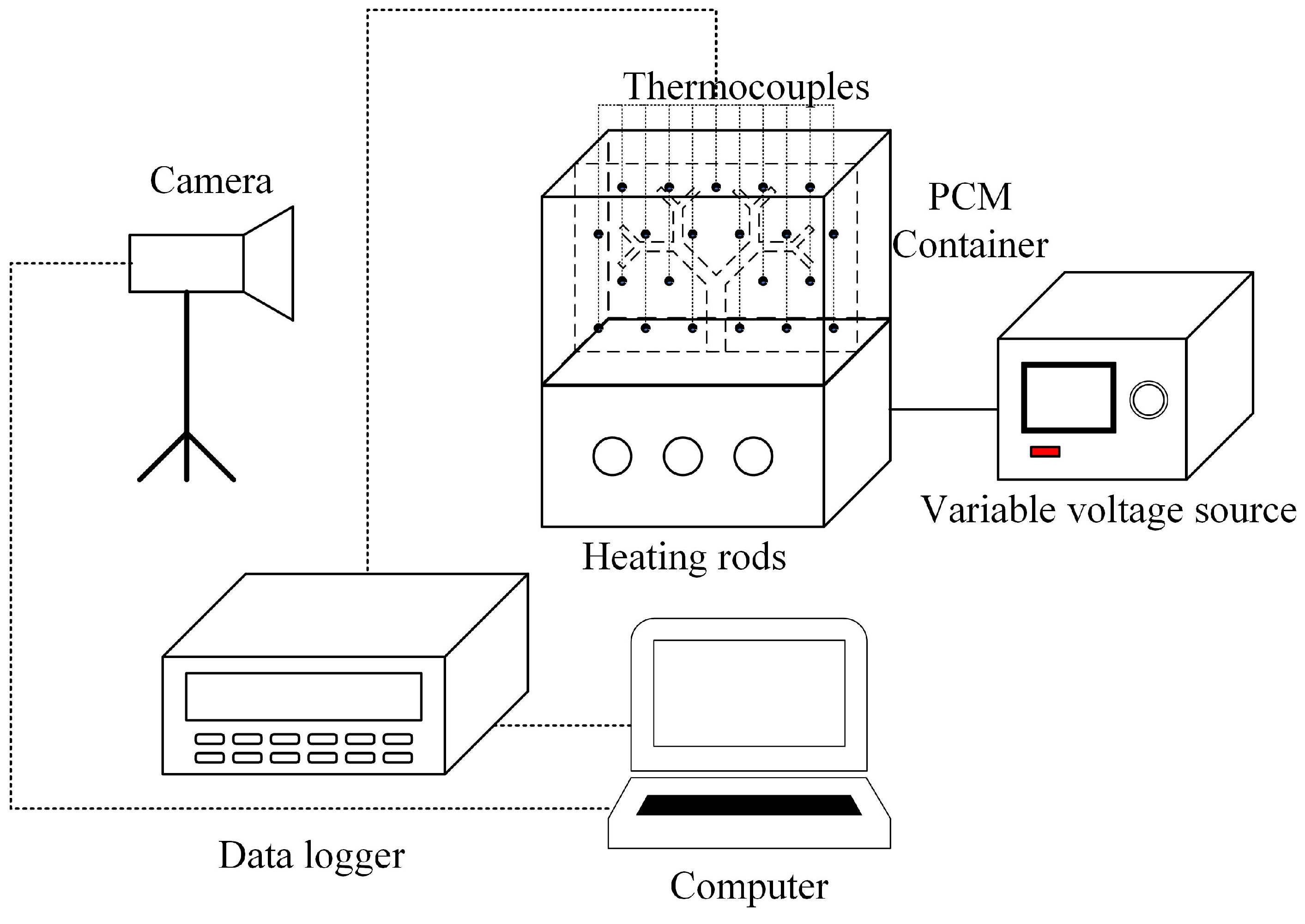
The instruments used in this experiment are shown in Figure 3. The experimental apparatus consists of a PCM container, electric heating rods, an AC voltage-regulated power supply, thermocouples, a temperature data logger, a personal computer and a high-speed camera.
The underside of the PCM container is made of 10 mm thick aluminum alloy. In order to monitor the temperature of the underside during the experiment, four T-type thermocouples were placed in four horizontal holes drilled about 2 mm above the hot surface. The remaining surfaces are made of 8 mm thick transparent plexiglass, which allows for the visual study of the melting process. The outside of the plexiglass shell is covered with a 30 mm thick EPDM insulation layer to reduce heat loss to the environment. The thermophysical properties of plexiglass and EPDM are shown in Table 1. AC voltage-regulated power supply and electric heating rods are used to achieve constant power heating during the melting process. In total, 22 T-type thermocouples are arranged in the middle section of the container to measure the transient temperature distribution in the container during the melting process of lauric acid. Figure 2 shows the arrangement of thermocouples in the PCM container. The thermocouples are connected to the computer through the temperature data logger.
In order to reduce air bubbles in the phase change unit, after heating the solid lauric acid to 100 °C in an incubator, the melted lauric acid is poured into the unit in a layer-by-layer manner, with the height of each layer within 10 mm. After the previous layer of lauric acid has been completely set, add the next layer until the entire unit is filled. The room temperature was controlled to 20 °C to establish constant initial conditions for all experiments.
During the experiment, the heating rod was kept at a constant power output of 27 watts. The thermal insulation material on the front of the phase change unit was removed at 1 min intervals and photographs were taken to visualize the change in the solid–liquid interface. The temperature data of the thermocouple was recorded every 10 s until all the lauric acid in the phase change unit melted. During the melting process, additional liquid lauric acid due to changes in the solid–liquid volume is exported to the radiator through the overflow port. In order to ensure the repeatability of the experiment, the experiment was repeated three times for each phase change units. The deviation was found to be negligible by comparing the change in liquid fraction in the three experiments.
The phase change material used in this experiment is lauric acid(C12H24O2), which is a fatty acid with a purity of 99%. It has the advantages of non-toxicity, good chemical stability, and medium-temperature phase change. The thermophysical properties of lauric acid [46] are shown in Table 1.

3. Results and Discussion

3.1. Solid–Liquid Interface

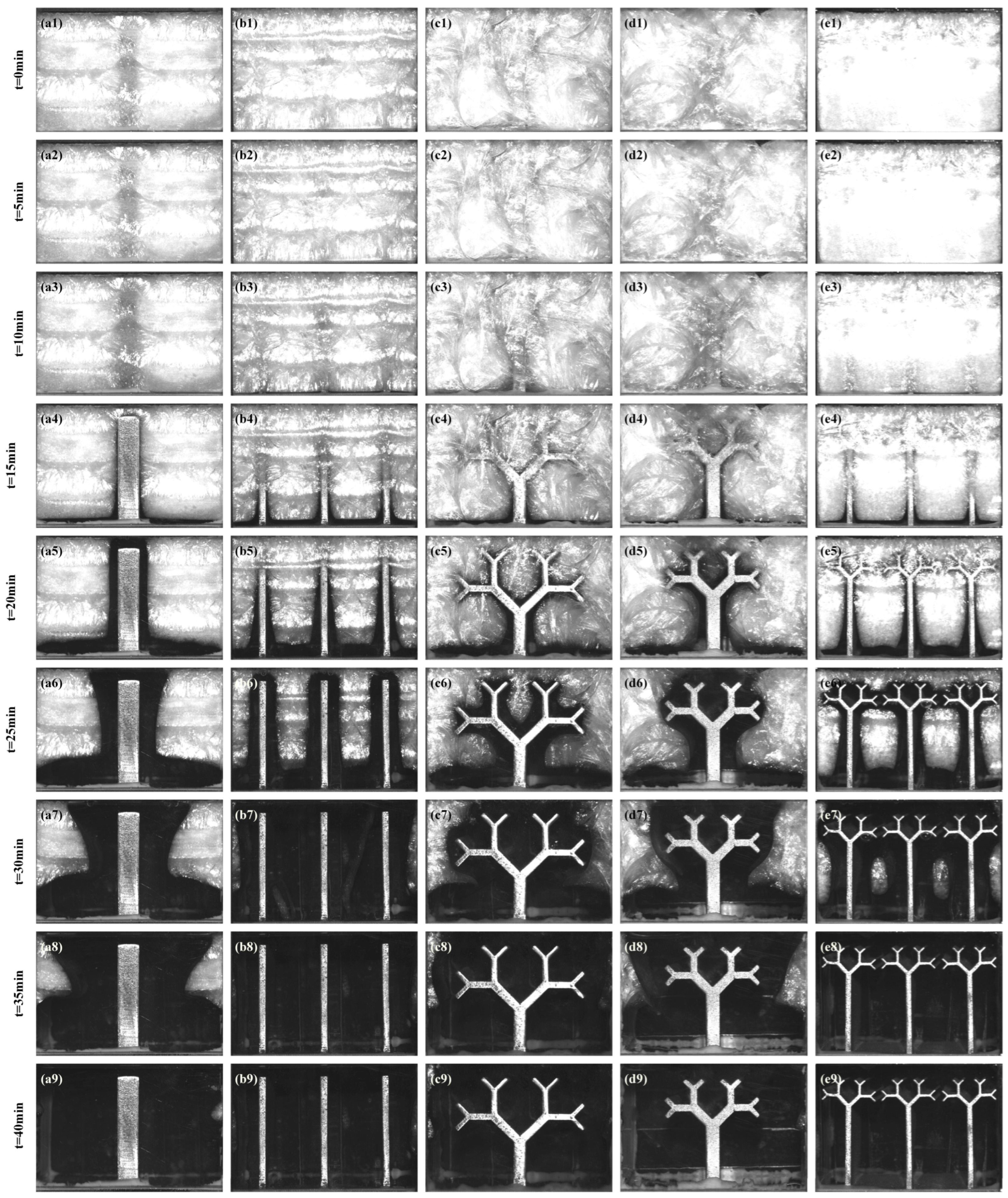
In order to better observe the melting behavior of lauric acid in different fin units, a visualization experiment was conducted at a heating power of 27 W and a room temperature of 20 °C. The evolution of the solid–liquid interface of each phase change unit during the heating process is depicted in Figure 4 at 5 min intervals. The white and black regions in the diagram correspond to the solid phase and liquid phase of lauric acid, respectively. Figure 5 is the solid–liquid interface position of each unit at 5 min intervals during the melting process obtained through image recognition.
Within the first 20 min of the melting process, as shown in Figure 5, it can be observed that the solid–liquid interface is almost parallel to the edge and bottom heating surface of the fin, which indicates that conduction is the main heat transfer mechanism. Meanwhile, due to bottom heating causing temperature gradients in the fins, it affects the melting rate of surrounding lauric acid, resulting in a gradual decrease in the width of the liquid phase region from the bottom to the top edge. For the phase change units with three fins such as the unit with rectangular fin 2 and the unit with tree-like fin 3, due to the fact that more fins divide the solid lauric acid into several small areas, the distance between the solid lauric acid and the heat source is shortened, and the EUR interface always maintains a mode of being basically parallel to the fins and the bottom surface, indicating that convection plays a smaller role in these two units, only manifesting itself in the end of the melting process. As can be seen from Figure 4b6,b7,e6,e7, due to the branched structure blocking the formation of circulation, the solid lauric acid between two fins melts slightly slower in the unit with tree-like fin 3 than in the unit with rectangular fin 2, indicating that the fractal fin inhibits natural convection at this time, which leads to the weakening of heat transfer more than the enhancement of thermal conductivity.
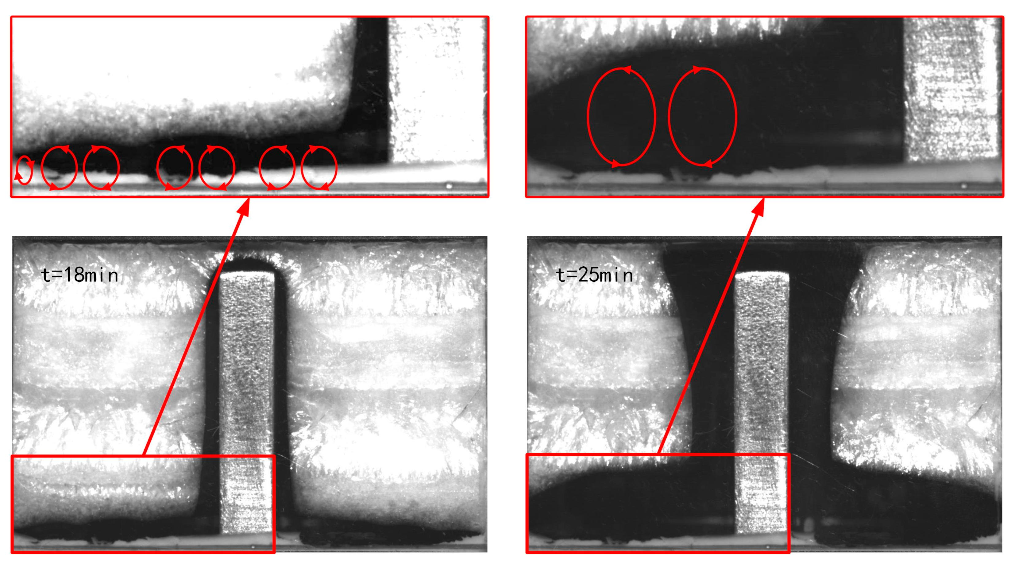
For the units with rectangular fin 1, tree-like fin 1 and tree-like fin 2, the promotion effect of convection on the melting process becomes prominent with the passage of time, especially in the unit with rectangular fin 1: the liquid lauric acid near the fin is further heated and rises along the fin. After reaching the top, the liquid lauric acid flow is blocked and then drops, which is cooled by the solid lauric acid in the process of descent, thus forming a solid–liquid interface inclined to the top, as shown in Figure 6a. With the development of the melt, the inclination of the liquid–solid interface increases gradually, as shown in Figure 6b, which indicates that the liquid lauric acid vortices formed on both sides of the fin are gradually larger. The curved solid–liquid interface at the bottom of the unit with rectangular fin 1 is caused by the circulation formed by the liquid lauric acid heated at the bottom. Figure 7 shows the reduction in the wave-like structure at the bottom of the solid–liquid interface over time, indicating that smaller vortices were merging into larger vortices over time. Figure 5 shows that during the melting process within 20–30 min, when the unit with rectangular fin 1 exhibits obvious convective effects, the solid–liquid interface of the units with tree-like fin 1 and tree-like fin 2 is still basically parallel to the fin edge, indicating that heat conduction still dominates. Meanwhile, the melting rate of the lauric acid in the peripheral area of the fin in these units is significantly faster than that of the unit with rectangular fin 1, which is related to the tree-like fin with a larger surface area and a more reasonable heat transfer path. The effect of convection started to appear when the solid–liquid interface completely separated from the tree-like fin. Thirty minutes after the heating began, the unit with tree-like fin 2 that has a smaller total width formed a solid–liquid interface similar to that of the unit with rectangular fin 1, which was obvious in Figure 4d8. However, due to the greater resistance to the convection of the fin structure, the unit with tree-like fin 1 only had a bending of the solid–liquid interface caused by the circulation on the bottom surface, and did not form a solid–liquid interface inclined to the top.

3.2. Liquid Fraction

The liquid fraction of each unit in the experiment was calculated by taking grayscale photos once per minute. The image resolution was 960 × 1440, corresponding to the 40 × 60 mm2 front part of the phase change unit. The quality of the taken photos was improved by filtering and converted into a binary image, in which the value of 0 corresponded to the liquid lauric acid part of the phase change unit and the value of 1 corresponded to the solid part.
The liquid fraction is defined as the ratio of the liquid area to the total area in the image [46]:
φ = N P 0 N P a l l
where NPall is the total number of pixels in the image, NP0 is the number of pixels with a value of 0. Taking into account the volume expansion during the melting process of lauric acid, Equation (1) is corrected to:
φ = N P 0 1 + β N P a l l + β N P 0  
where β is the volume change caused by solid–liquid phase change.
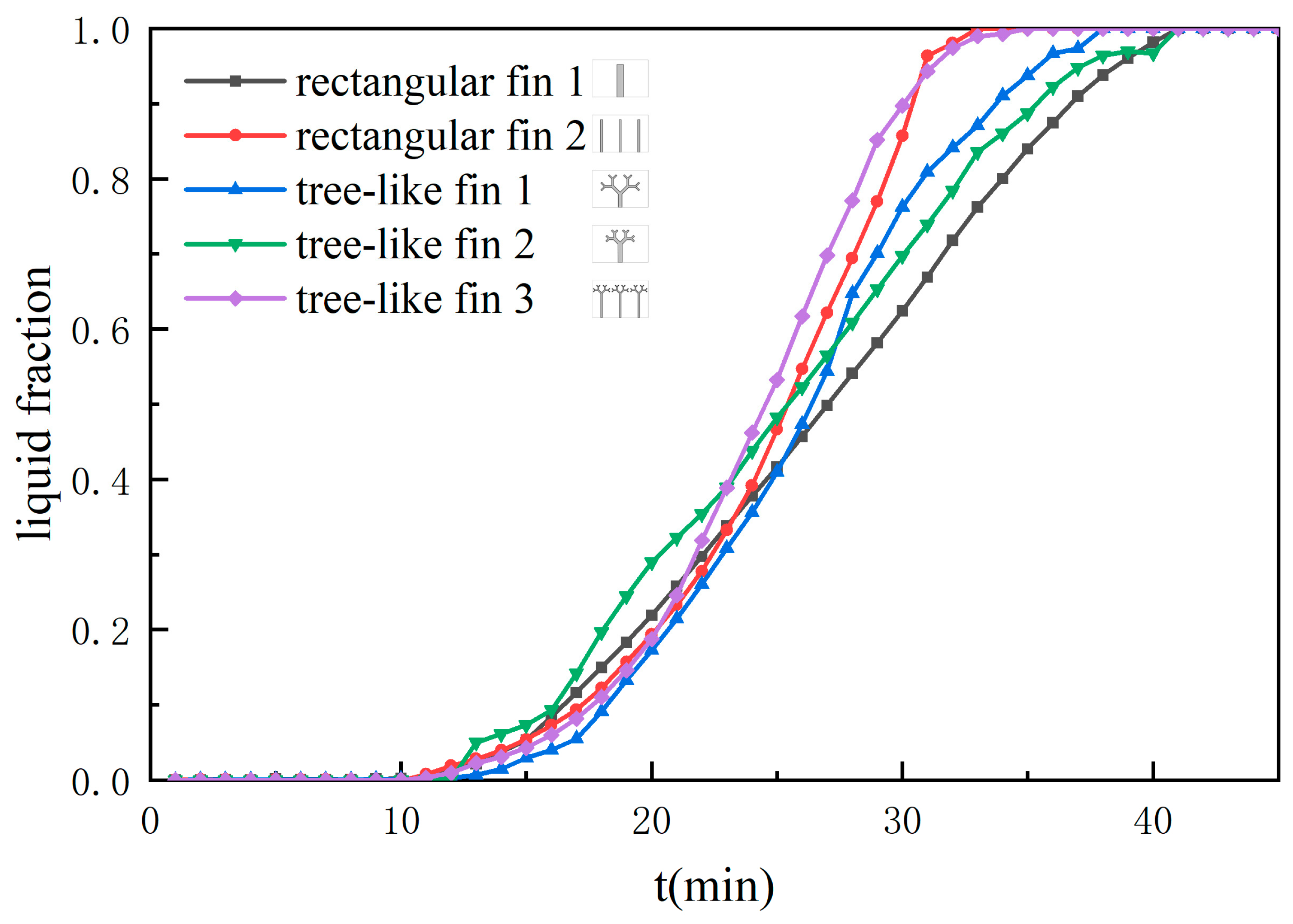
Figure 8 shows the variation of liquid fraction during the melting process of different phase change units. In the five phase change units with different fins, the slope of the liquid fraction increases first and then decreases, among which the two three-fin units have the fastest melting rate, which is related to the rapid melting of lauric acid around the fins within 15–30 min. Compared with the three one-fin units, the average distance between lauric acid and fins is shorter in the unit with rectangular fin 2 and the unit with tree-like fin 3, which greatly enhances the thermal conductivity. After 30 min of heating, the unit with tree-like fin 3 melted slower than the unit with rectangular fin 2. This is because the branched structure of the tree-like fin impedes the development of convection within the unit, thus hindering the melting of the lauric acid at the corner of the unit and between the fins, which is consistent with the analysis of the interface changes above.
Among the three one-fin units, the full melting time of the unit with tree-like fin 1 is the shortest. But in the early stage, the melting rates of the unit with tree-like fin 2 are faster than that of the unit with tree-like fin 1, which may be related to the higher thermal resistance of the structure of tree-like fin 1. Since the tree-like fins are generated by Equation (1), the length–width ratio of each level is equal. The length–width ratio lk/wk of tree-like fin 1 is 3.55, while lk/wk of tree-like fin 2 is 2.06, which means that the thermal resistance of tree-like fin 1 is greater than that of tree-like fin 2.
After the lauric acid adjacent to the fin melts, the branched structure of tree-like fin 1 is more conducive to heat transfer from point to surface, so the melting rate surpasses the other two units.
Table 3 shows the full melting time tall and melting time ratio rt for each unit. In order to quantitatively compare the enhancement effects of different fins on melting, the melting time ratio rt is defined as the ratio of the full melting time of other units to the full melting time of a unit with rectangular fin 1. Among the five phase change units, the unit with the shortest full melting time is the unit with rectangular fin 2, which takes 32 min, 21.95% less than the unit with rectangular fin 1 serving as the reference. Among the three one-fin units, the unit with the shortest full melting time is the unit with tree-like fin 1, which takes 9.76% less time than the rectangular fin 1 unit. The results show that increasing the number of fins and optimizing the fin shape can shorten the melting time, and increasing the number of fins has the most significant effect on shortening the melting time. When the number of fins remains unchanged, the unit with the most reasonable heat transfer structure, the unit with tree-like fin 1, has the shortest full melting time.

3.3. Temperature Distribution

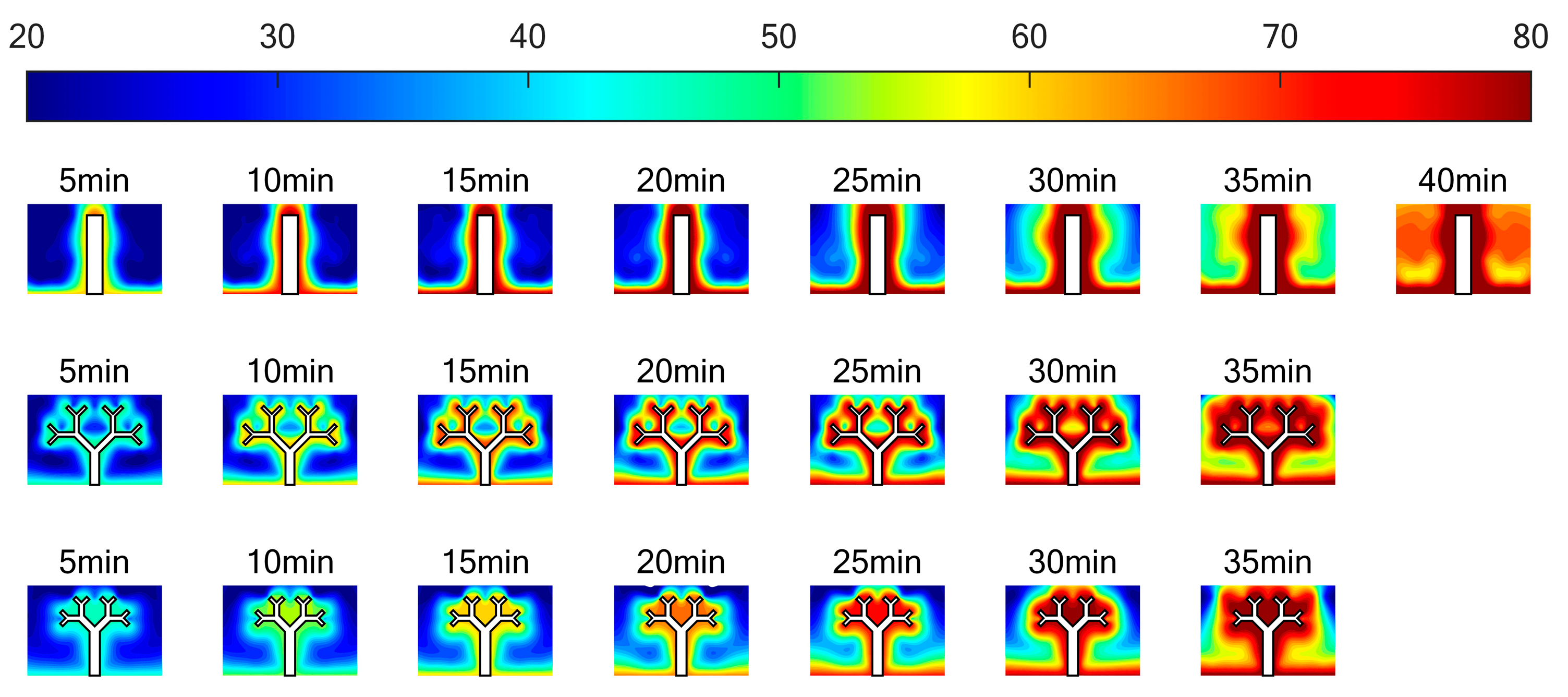
Figure 9 and Figure 10 depict the temperature distribution of the vertical section in the middle of the phase change unit after interpolating temperature data recorded by thermocouples at a time interval of 5 min. The temperature distribution reflects a similar trend to that of the phase change interface. For the unit with rectangular fin 1, as shown in Figure 9, isotherms are almost parallel to the fin and its bottom surface within 20 min, indicating that heat transfer mainly occurs through conduction while some regions deviating from the fin edge are affected by staggered thermocouple distribution points. As time passes, liquid lauric acid near the fin rises in temperature and decreases in density, causing it to rise along with the fin until it reaches the top of the unit where it heats the surrounding solid lauric acid, forming sloping isotherms along with branched structure fins. The branched structure of tree-like fin 1 facilitates heat conduction throughout the phase change unit. During the melting process, no local high-heat area similar to the unit with rectangular fin 1 forms around tree-like fin 1, indicating less contribution from convection towards the melting process. The unit with tree-like fin 2 shows a similar trend as the unit with tree-like fin 1 during the early stages of melting. However, 30 min after the start of heating, due to the small total width of fins, after the lauric acid around the fins was completely melted, the solid–liquid interface separated from the fins, and a high-heat liquid lauric acid area around the fins was formed. The enhancement of heat conduction of the branched structure has been greatly weakened; at the same time, the tree-like fin hindered the development of convection, thus having an adverse effect on the melting rate and temperature uniformity.
Figure 10 shows the temperature distribution of the unit with rectangular fin 2 and the unit with tree-like fin 3. Compared with the three one-fin units, the temperature distribution of the tree-fin units is obviously more uniform, and there is almost no local high-heat area, indicating that heat conduction plays a dominant role in the whole melting process. The influence of fin shape on the melting process became apparent 30 min after the melting begins: the top branched structure tree-like fin 3 accelerates the melting of lauric acid on the upper part of the unit, but it also affects the formation of circulation between fins, resulting in a rectangular area with a lower temperature between the fins.
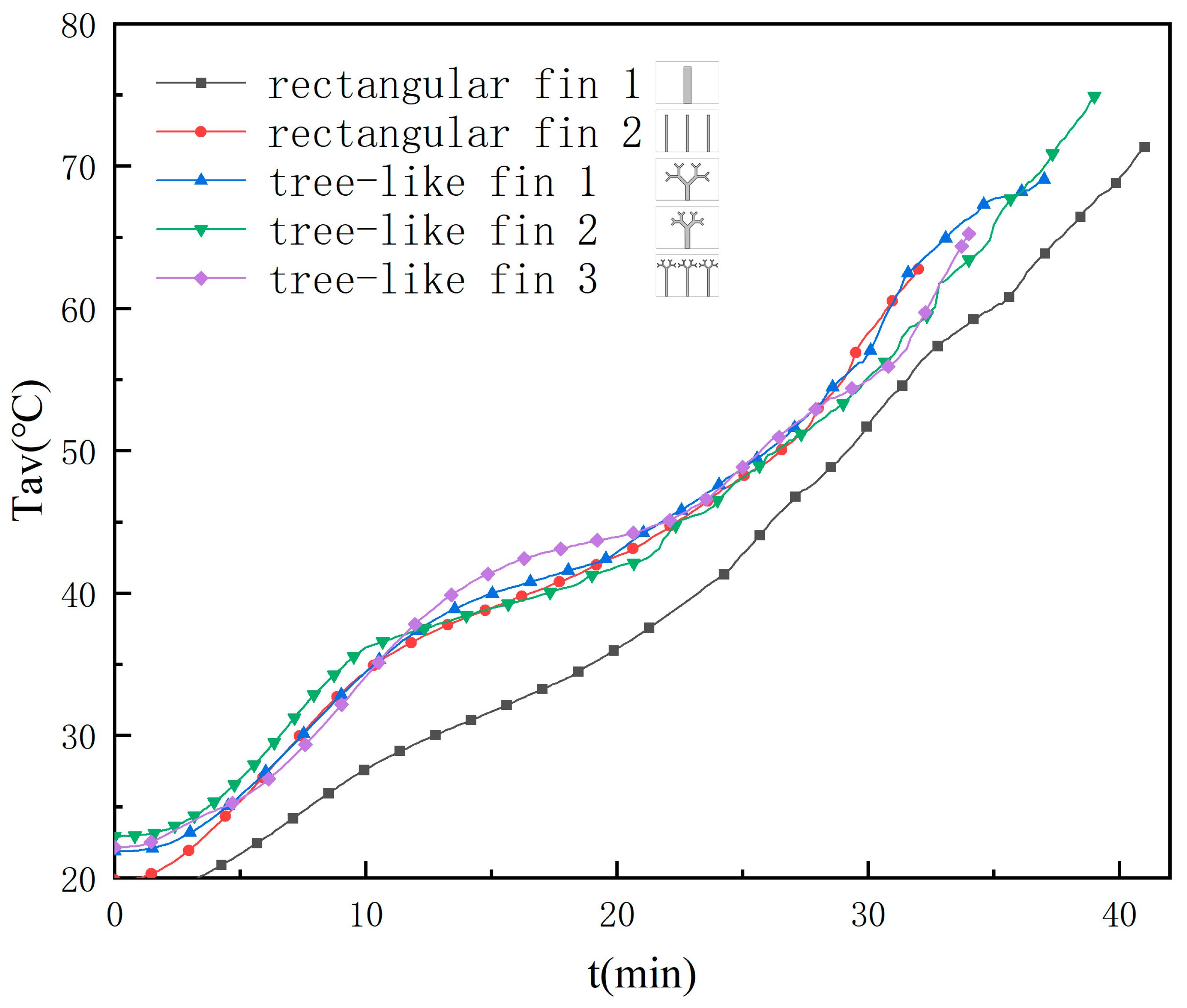
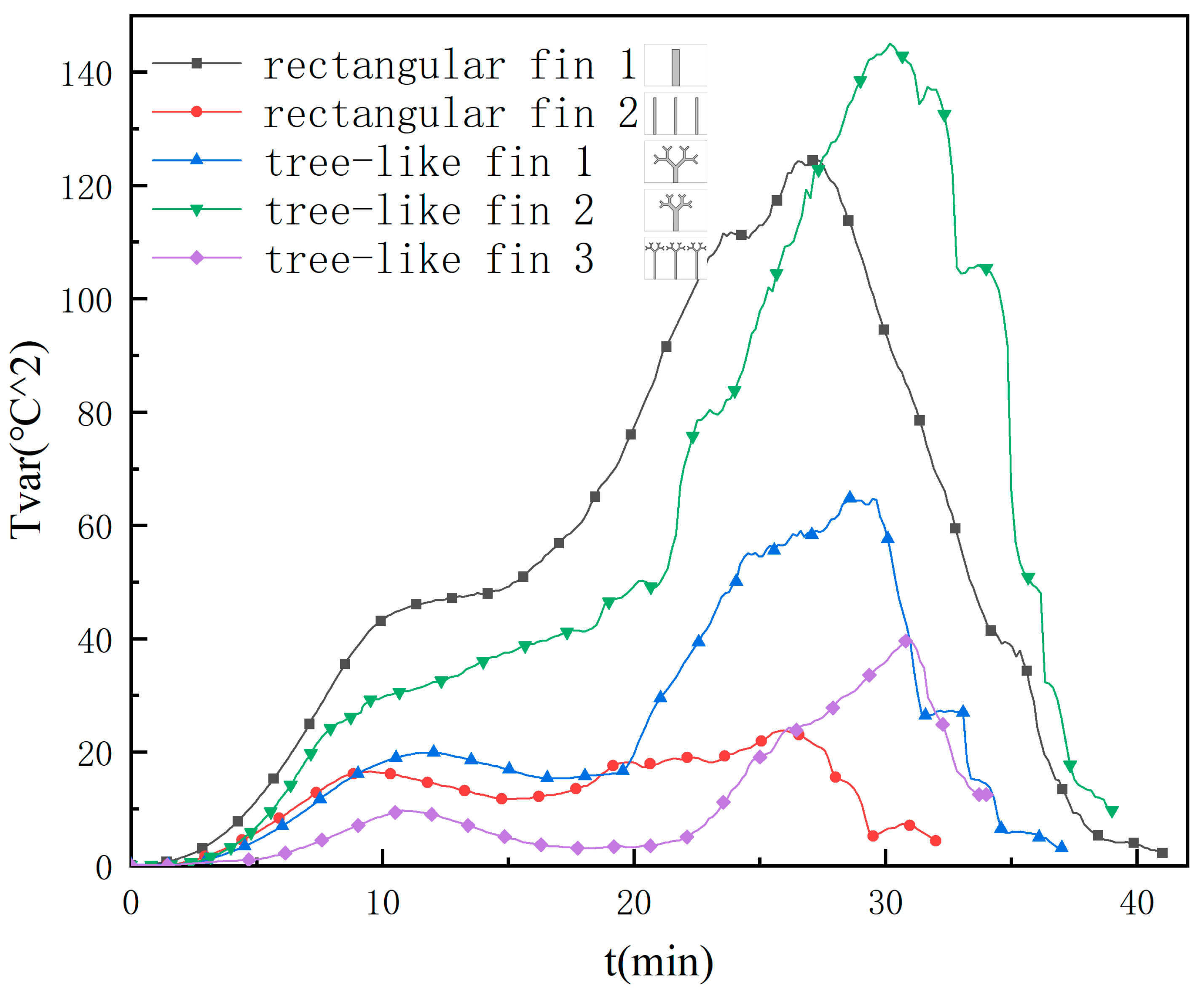
Figure 11 and Figure 12 show the average temperature and variance within the phase change units during the melting process, with temperature data obtained from thermocouples. The average temperature of each unit undergoes three stages: a rapid increase, a steady rise, and another rapid increase, while the variance change has the same trend of rapid increase, steady rise, another rapid increase, and a sharp decline. In the first 10 min of melting, most of the lauric acid in the unit is solid, and heat transfer is mainly conducted in the form of heat conduction. Therefore, there is a large temperature difference between the thermocouple measuring points close to the fins and far away from the fins. In this period, the two three-fin units have the lowest temperature variance due to more fins making each measuring point relatively close to the fins. During the 10–25 min of melting, as the lauric acid melts, the latent heat of phase change slows down the average temperature rise, while the temperature variance remains almost unchanged. It can be seen from the changes in variance that the unit with rectangular fin 1 enters this stage earliest and also enters the next stage earliest, which is related to the smaller surface area of rectangular fin 1 and the shortest rapid melting stage of lauric acid around the fin. Twenty-five minutes after the start of heating, most of the lauric acid has melted, and the latent heat of phase change has a smaller effect on suppressing temperature changes, so the average temperature and temperature variance rise rapidly again. The final stage of rapid decline in variance corresponds to the last 10 min of the melting process of each unit. At this time, most of the units have been filled with liquid lauric acid with a small temperature difference, but solid lauric acid that melts slowly is still present in the corners.
When the melting process was completed, the average temperature of the three-fin units was lower than that of the one-fin units, and the variance was also smaller during the melting process, which was consistent with the above temperature field, indicating that the increase in fin number is beneficial for the uniform temperature in the phase change unit. Among the three units with one fin, the unit with tree-like fin 1, which has the most favorable structure for heat transfer and the largest surface area, had the lowest average temperature and the smallest variance at the end of melting, showing the good promotion of heat transfer by the tree-like fin.
Figure 13 shows the variation of the bottom surface temperature Tb during the melting process, which is the average temperature measured by the four thermocouples placed on the bottom surface of the phase change unit. Tb rose rapidly in the first 15 min of melting. and then the rise became gradual as lauric acid melted. As the lauric acid melted, the rise became gentle and remained at a relatively gradual rising trend until all the lauric acid in the unit melted, corresponding to the stages dominated by sensible heat and latent heat of the melting process, respectively. The gentle change in Tb during the stage dominated by latent heat absorption shows the advantages of LHTES in temperature control. Among the five phase change units, Tb of the two three-fin units were always lower, indicating that increasing the number of fins is beneficial to controlling the bottom surface temperature. At the end of the phase change process, the bottom surface temperatures of the unit with rectangular fin 2 and the unit with tree-like fin 3 were reduced by 27.41% and 27.47%, respectively, compared with the unit with rectangular fin 1. In units with the same number of fins, the bottom surface temperature of the unit with tree-like fin is lower than that of the unit with rectangular fin, indicating that the branched structure has a greater enhancement effect on heat conduction than on convection in the unit described in this paper, which is beneficial for controlling the bottom surface temperature.

3.4. Heat Transfer Characteristics

During heating, lauric acid absorbs heat in both sensible and latent forms. The amount of sensible energies is related to the state and temperature of the phase change material, which can be calculated by the following equation [46]:
Q s e n s i b l e t = V s t ρ s c p , s T m e a n , s t T 0 d V s + V l t ρ s c p , s T s T 0 d V l + V l t ρ l c p , l T m e a n , l t T l d V l
where Vs and Vl are the volumes of solid and liquid lauric acid in the melting process, respectively; ρs and ρl are the densities of solid and liquid lauric acid; cp,s and cp,l are the specific heat capacity of solid and liquid lauric acid; Ts and Tl are the starting and ending temperatures of lauric acid phase change; T0 is the initial temperature of the unit; Tmean,s and Tmean,l are the average temperature readings of thermocouples placed in the solid phase and liquid lauric acid.
T m e a n , s t = 1 n s t j = 1 n s t T j
T m e a n , l t = 1 n l t j = 1 n l t T j
ns(t) and nl(t) are the number of thermocouples in the solid or liquid part of lauric acid.
In Equation (4), the first integral represents the sensible heating of the solid PCM in the unit at the current time. The second and the third integral represent the sensible heating of the liquid PCM in the unit, where the second integral is the sensible heat gain by T0 to its melting start point, and the third term accounts for superheating of the melted PCM. Latent heat is calculated as:
Q l a t e n t t = ρ l φ t V 1 + β φ t L
The total heat is the sum of latent heat and sensible heat:
Q t o t a l t = Q s e n s i b l e t + Q l a t e n t t  
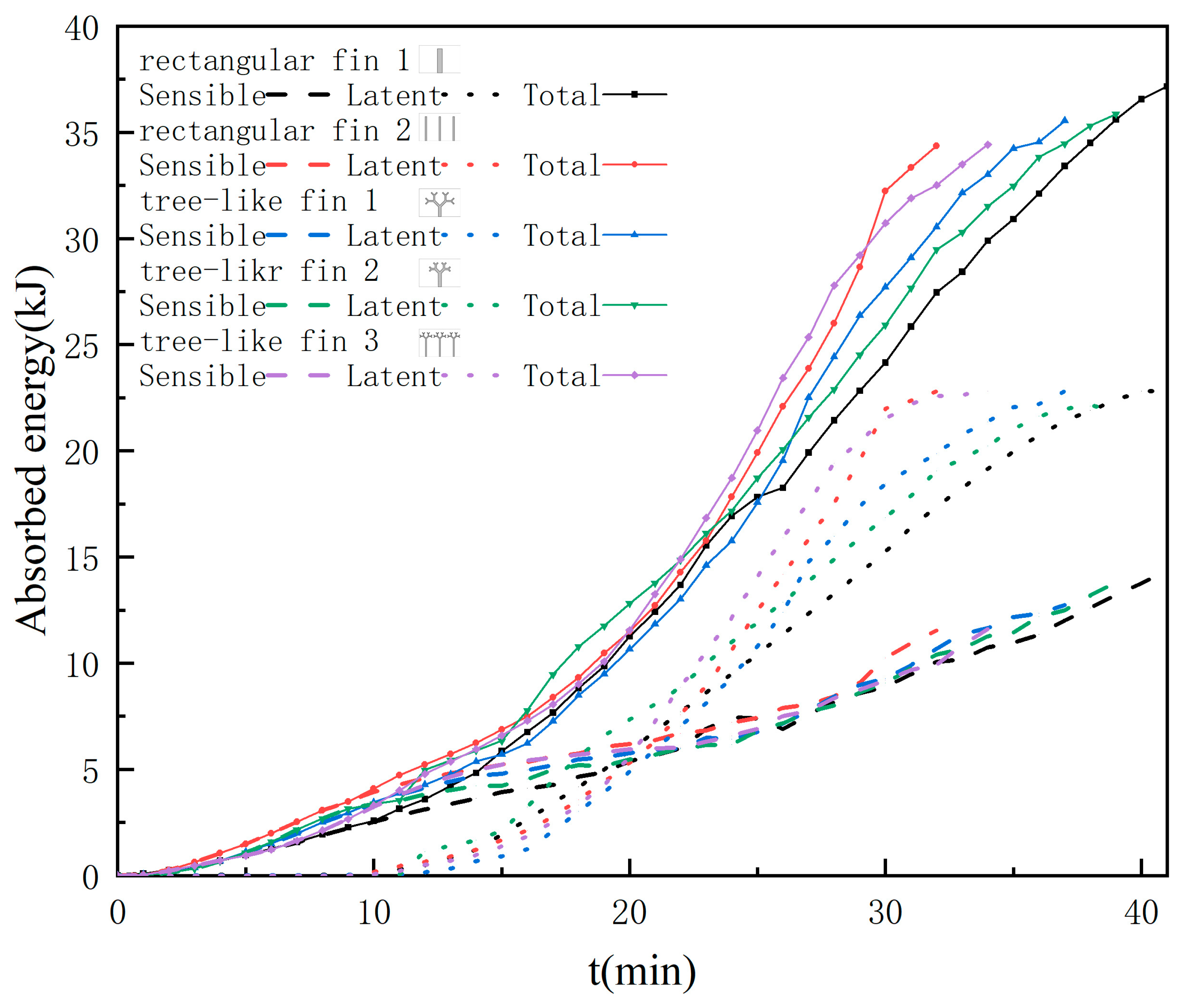
Figure 14 shows the changes in sensible heat, latent heat, and total heat during the melting process for five phase change units. The latent heat is proportional to the mass of the phase change material, and since the volume and the proportion of the fin of each unit are equal, the mass of lauric acid in each unit is also equal. Therefore, the latent heat of each unit is the same when the melting process ends. The difference in total heat is only related to the average temperature of each unit at the end of the melting process. During the melting process, the trend of latent heat of each unit is the same as the trend of liquid fraction: latent heat of the unit with rectangular fin 2 and the unit with tree-like fin 3 rose fastest; among the three units with one fin, the unit with tree-like fin 2 and the unit with tree-like fin 1 have the leading latent heat in turn. There is a rapid increase in latent heat from 15 to 30 min during the melting process, while the sensible heat remains almost unchanged, which is related to the fact that the latent heat suppresses the increase in the temperature in the unit.
The heat transfer rate from the heating surface to the phase change material in Δt can be expressed as:
Q ˙ t = Q t + Δ t Q t Δ t
Figure 15 shows the changes in heat transfer rate of each unit during the heating process. In the first 10 min of melting, due to the low temperature of the heating surface, the heat transfer rate of each unit is low. With the increase in the temperature of the bottom surface, the heat transfer rate gradually increases and reaches a peak in the rapid melting stage of lauric acid around the fin, about 25–30 min after the beginning of heating. Subsequently, the heat transfer rate decreased rapidly with the thickening of the liquid layer. In the whole melting process, the heat transfer rates of the unit with rectangular fin 2 and the unit with tree-like fin 3 were higher than that of the three one-fin units. The heat transfer rate of the unit with tree-like fin 3 reaches its peak earlier than that of the unit with rectangular fin 2, reflecting the promoting effect of the tree-like fin on the lauric acid melting around the fin. The heat transfer rate peak of the unit with tree-like fin 2 was earlier than that of the unit with tree-like fin 1, but later, the heat transfer rate was lower than the latter, which is consistent with the trend of the change in the interface in Figure 4. The unit with tree-like fin 2 is favorable for early heat transfer due to the smaller thermal resistance, but its promoting effect on heat conduction is weakened after the liquid layer around the fin thickens.
The average heat transfer coefficient between the fin surface and liquid lauric acid [46] can be obtained from:
h ¯ t = Q t o t a l t A w T w T m Δ t
where Qtotal(t) is the total heat absorbed by the phase change material from the heat source in Δt; Aw is the heating surface area, whose value is shown in Table 1.
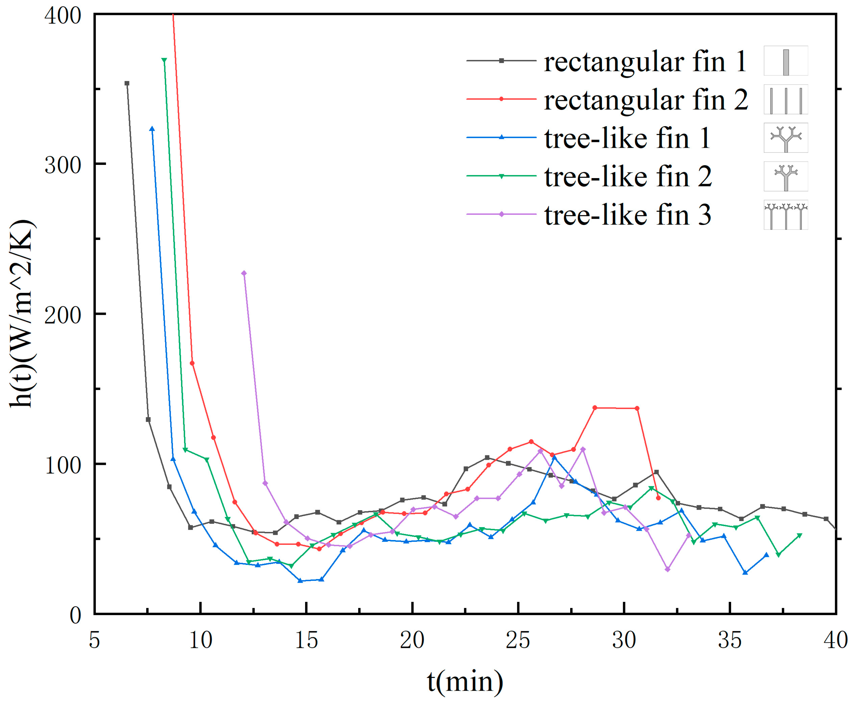
Figure 16 shows the instantaneous changes in the average heat transfer coefficient after the liquid fraction is greater than 0, reflecting the existence of different heat transfer mechanisms in each unit during the melting process. At the beginning of the melting process, when the liquid fraction is extremely low, h ¯ t has a larger value, which can be attributed to the smaller thermal resistance of the thinner liquid layer. In the first 10–15 min when heat conduction dominates, h ¯ t decreases rapidly and reaches a minimum value. Subsequently, with the development of convection in the unit, there was a small recovery of h ¯ t at 15–25 min of melting. But it finally dropped again due to the decrease in the temperature difference within the unit. In this stage, h ¯ t of the unit with rectangular fin 1 is usually higher than other units, indicating that this fin has the least obstruction to convection. After about 30 min of the melting process, h ¯ t of the unit with rectangular fin 2 reaches a small peak, while the unit with tree-like fin 3, which also has three fins, does not show a noticeable peak, indicating that the branched structure has a significant hindrance on convection during this stage.

4. Summary

This paper focuses on the design of tree-like fractal fins to enhance the heat transfer performance of the phase change units during the melting process. Experimental investigations are conducted to analyze the changes in the solid–liquid interface, temperature response characteristics, and heat transfer characteristics of three different phase change units with tree-like fins, which are then compared with corresponding units with rectangular fins. The key findings can be summarized as follows:
  • The tree-like fins significantly improve the heating performance of LHTES. Among the one-fin units, compared with the rectangular fin, the full melting time of the unit with tree-like fin 1 is reduced by 9.76% because the improvement of the heat conduction of the tree-like fins is greater than the inhibition of natural convection.
  • The tree-like fins are beneficial to controlling the heating surface temperature. At the end of the melting process, the bottom surface temperatures of the two units with tree-like fins were 14.42% and 13.19% lower than that of the unit with rectangular fin 1. The branched structure facilitates the conduction of heat from point to surface, making the temperature distribution more uniform during the melting process.
  • The structure and number of fins are two key factors that affect the heat transfer performance of the LHTES unit. Increasing the number of fins can enhance heat transfer within the phase change unit. Compared with the unit with one rectangular fin, the full melting time of the unit with three rectangular fins and the unit with three tree-like fins are reduced by 21.95% and 17.07%, respectively, and the temperature distribution within the unit is more uniform. However, as the number of fins increases, the suppression of natural convection by the tree-like fin may exceed the enhancement of heat conduction, which results in a lower heat transfer performance of the unit with tree-like fin 3 compared to the unit with rectangular fin 2.

Author Contributions

Conceptualization, Z.G. and L.X.; methodology, Z.G.; writing—original draft preparation, Z.G.; writing—review and editing, Z.G., L.X., F.S. and S.S. All authors have read and agreed to the published version of the manuscript.

Funding

This study was supported by National Key R&D Program of China (No. 2023YFE0119800).

Data Availability Statement

The original contributions presented in the study are included in the article, further inquiries can be directed to the corresponding author.

Conflicts of Interest

The authors declare no conflicts of interest.

References

  1. Cabeza, L.F.; Sole, C.; Castell, A.; Oro, E.; Gil, A. Review of Solar Thermal Storage Techniques and Associated Heat Transfer Technologies. Proc. IEEE 2012, 100, 525–538. [Google Scholar] [CrossRef]
  2. Li, D.; Wang, J.; Ding, Y.; Yao, H.; Huang, Y. Dynamic thermal management for industrial waste heat recovery based on phase change material thermal storage. Appl. Energy 2019, 236, 1168–1182. [Google Scholar] [CrossRef]
  3. Zhang, Y.P.; Lin, K.P.; Yang, R.; Di, H.F.; Jiang, Y. Preparation, thermal performance and application of shape-stabilized PCM in energy efficient buildings. Energy Build. 2006, 38, 1262–1269. [Google Scholar] [CrossRef]
  4. Tao, Y.B.; He, Y.-L. A review of phase change material and performance enhancement method for latent heat storage system. Renew. Sustain. Energy Rev. 2018, 93, 245–259. [Google Scholar] [CrossRef]
  5. Wang, C.; Lin, T.; Li, N.; Zheng, H. Heat transfer enhancement of phase change composite material: Copper foam/paraffin. Renew. Energy 2016, 96, 960–965. [Google Scholar] [CrossRef]
  6. Xiao, X.; Zhang, P.; Li, M. Effective thermal conductivity of open-cell metal foams impregnated with pure paraffin for latent heat storage. Int. J. Therm. Sci. 2014, 81, 94–105. [Google Scholar] [CrossRef]
  7. Liu, Z.; Yao, Y.; Wu, H. Numerical modeling for solid–liquid phase change phenomena in porous media: Shell-and-tube type latent heat thermal energy storage. Appl. Energy 2013, 112, 1222–1232. [Google Scholar] [CrossRef]
  8. Deng, Z.; Liu, X.; Zhang, C.; Huang, Y.; Chen, Y. Melting behaviors of PCM in porous metal foam characterized by fractal geometry. Int. J. Heat Mass Transf. 2017, 113, 1031–1042. [Google Scholar] [CrossRef]
  9. Nemati, H.; Souriaee, V.; Habibi, M.; Vafai, K. Design and Taguchi-based optimization of the latent heat thermal storage in the form of structured porous-coated pipe. Energy 2023, 263, 125947. [Google Scholar] [CrossRef]
  10. Wang, J.; Xie, H.; Xin, Z.; Li, Y.; Chen, L. Enhancing thermal conductivity of palmitic acid based phase change materials with carbon nanotubes as fillers. Sol. Energy 2010, 84, 339–344. [Google Scholar] [CrossRef]
  11. Lohrasbi, S.; Sheikholeslami, M.; Ganji, D.D. Discharging process expedition of NEPCM in fin-assisted Latent Heat Thermal Energy Storage System. J. Mol. Liq. 2016, 221, 833–841. [Google Scholar] [CrossRef]
  12. Zheng, Y.; Zhao, W.; Sabol, J.C.; Tuzla, K.; Neti, S.; Oztekin, A.; Chen, J.C. Encapsulated phase change materials for energy storage—Characterization by calorimetry. Sol. Energy 2013, 87, 117–126. [Google Scholar] [CrossRef]
  13. Felix Regin, A.; Solanki, S.C.; Saini, J.S. An analysis of a packed bed latent heat thermal energy storage system using PCM capsules: Numerical investigation. Renew. Energy 2009, 34, 1765–1773. [Google Scholar] [CrossRef]
  14. Sarı, A.; Alkan, C.; Bilgin, C. Micro/nano encapsulation of some paraffin eutectic mixtures with poly(methyl methacrylate) shell: Preparation, characterization and latent heat thermal energy storage properties. Appl. Energy 2014, 136, 217–227. [Google Scholar] [CrossRef]
  15. Yuan, Y.; Cao, X.; Xiang, B.; Du, Y. Effect of installation angle of fins on melting characteristics of annular unit for latent heat thermal energy storage. Sol. Energy 2016, 136, 365–378. [Google Scholar] [CrossRef]
  16. Baby, R.; Balaji, C. Thermal optimization of PCM based pin fin heat sinks: An experimental study. Appl. Therm. Eng. 2013, 54, 65–77. [Google Scholar] [CrossRef]
  17. Shahsavar, A.; Goodarzi, A.; Mohammed, H.I.; Shirneshan, A.; Talebizadehsardari, P. Thermal performance evaluation of non-uniform fin array in a finned double-pipe latent heat storage system. Energy 2020, 193, 116800. [Google Scholar] [CrossRef]
  18. Baghaei Oskouei, S.; Bayer, Ö. Experimental and numerical investigation of melting and solidification enhancement using Fibonacci-inspired fins in a latent thermal energy storage unit. Int. J. Heat Mass Transf. 2023, 210, 124180. [Google Scholar] [CrossRef]
  19. Zhang, Y.; Lu, B.; Wang, Z.; Zhu, J.; Zhang, J.; Wang, C. Experimental investigation on the charging and discharging performance enhancement of a vertical latent heat thermal energy storage unit via snowflake fin design. Int. J. Heat Mass Transf. 2022, 199, 123455. [Google Scholar] [CrossRef]
  20. Triki, R.; Chtourou, S.; Baccar, M. Heat transfer enhancement of phase change materials PCMs using innovative fractal H-shaped fin configurations. J. Energy Storage 2023, 73, 109020. [Google Scholar] [CrossRef]
  21. Du, J.; Bai, D.; Meng, X.; Jiao, F.; Hong, Y. Effect of Cantor fractal fin arrangements on the thermal performance of a photovoltaic-phase change material system: An experimental study. Int. J. Heat Mass Transf. 2024, 219, 124853. [Google Scholar] [CrossRef]
  22. Wu, L.; Zhang, X.; Liu, X. Numerical analysis and improvement of the thermal performance in a latent heat thermal energy storage device with spiderweb-like fins. J. Energy Storage 2020, 32, 101768. [Google Scholar] [CrossRef]
  23. Bejan, A. Constructal tree-shaped paths for conduction and convection. Int. J. Energy Res. 2003, 27, 283–299. [Google Scholar] [CrossRef]
  24. Huang, G.; Zhu, Y.; Liao, Z.; Xu, R.; Jiang, P.-X. Biomimetic self-pumping transpiration cooling for additive manufactured porous module with tree-like micro-channel. Int. J. Heat Mass Transf. 2019, 131, 403–410. [Google Scholar] [CrossRef]
  25. Xu, S.; Guo, Z.; Qin, J.; Cai, Q.; Hu, G.; Wang, W. Three Dimensional Numerical Simulation of Fluid Flow and Heat Transfer in Tree-shaped Microchannels. China Mech. Eng. 2014, 25, 1185–1188. [Google Scholar]
  26. Xue, Z.; Yan, Y.; He, Z.; Shen, K.; Zhang, C. Exergy analysis and energy output improvement of the micro-thermophotovoltaic system via investigating the fractal angles of secondary Y-shaped fins in the micro combustor. Fuel 2023, 334, 126504. [Google Scholar] [CrossRef]
  27. Calamas, D.; Baker, J. Tree-like branching fins: Performance and natural convective heat transfer behavior. Int. J. Heat Mass Transf. 2013, 62, 350–361. [Google Scholar] [CrossRef]
  28. Li, F.; Sheikholeslami, M.; Dara, R.N.; Jafaryar, M.; Shafee, A.; Nguyen-Thoi, T.; Li, Z. Numerical study for nanofluid behavior inside a storage finned enclosure involving melting process. J. Mol. Liq. 2020, 297, 111939. [Google Scholar] [CrossRef]
  29. Yıldız, Ç.; Arıcı, M.; Nižetić, S.; Shahsavar, A. Numerical investigation of natural convection behavior of molten PCM in an enclosure having rectangular and tree-like branching fins. Energy 2020, 207, 118223. [Google Scholar] [CrossRef]
  30. Vogel, J.; Johnson, M. Natural convection during melting in vertical finned tube latent thermal energy storage systems. Appl. Energy 2019, 246, 38–52. [Google Scholar] [CrossRef]
  31. Li, Q.; Jiang, J.; Hong, Y.; Du, J. Numerical investigation of thermal management performances in a solar photovoltaic system by using the phase change material coupled with bifurcated fractal fins. J. Energy Storage 2022, 56, 106156. [Google Scholar] [CrossRef]
  32. Luo, X.M.; Gu, J.A.; Ma, H.Q.; Xie, Y.; Li, A.Y.; Wang, J.Y.; Ding, R.X. Numerical study on enhanced melting heat transfer of PCM by the combined fractal fins. J. Energy Storage 2022, 45, 103780. [Google Scholar] [CrossRef]
  33. Peng, H.; Yan, W.; Wang, Y.; Feng, S. Discharging process and thermal evaluation in the thermal energy storage system with fractal tree-like fins. Int. J. Heat Mass Transf. 2022, 183, 122073. [Google Scholar] [CrossRef]
  34. Shi, S.; Niu, J.; Wu, Z.; Luo, S.; Gao, X.; Fang, Y.; Zhang, Z. Experimental and numerical investigation on heat transfer enhancement of vertical triplex tube heat exchanger with fractal fins for latent thermal energy storage. Int. J. Heat Mass Transf. 2022, 198, 123386. [Google Scholar] [CrossRef]
  35. Jiang, J.; Hong, Y.; Li, Q.; Du, J. Numerical analysis on heat transfer and melting characteristics of a solid-liquid phase change process in a rectangular cavity inserted with bifurcated fractal fins. Int. Commun. Heat Mass Transf. 2023, 142, 106616. [Google Scholar] [CrossRef]
  36. Li, W.; Wang, J.; Zhang, Y.; Zhang, X.; Wei, F.; Zhao, J. Numerical study and parametric analysis on performance enhancement of a latent heat storage unit with fractal fins. J. Energy Storage 2022, 55, 105814. [Google Scholar] [CrossRef]
  37. Yu, D.; Qiu, Y.; Zhang, X.; Liu, F. Research on the energy discharging performance of Y-shaped fin. J. Energy Storage 2022, 50, 104704. [Google Scholar] [CrossRef]
  38. Sciacovelli, A.; Gagliardi, F.; Verda, V. Maximization of performance of a PCM latent heat storage system with innovative fins. Appl. Energy 2015, 137, 707–715. [Google Scholar] [CrossRef]
  39. Deng, Z.L.; Wu, S.C.; Xu, H.; Chen, Y.P. Melting heat transfer enhancement of a horizontal latent heat storage unit by fern-fractal fins. Chin. J. Chem. Eng. 2020, 28, 2857–2871. [Google Scholar] [CrossRef]
  40. Luo, X.M.; Liao, S.M. Numerical Study on Melting Heat Transfer in Dendritic Heat Exchangers. Energies 2018, 11, 2504. [Google Scholar] [CrossRef]
  41. Huang, Y.; Liu, X. Charging and discharging enhancement of a vertical latent heat storage unit by fractal tree-shaped fins. Renew. Energy 2021, 174, 199–217. [Google Scholar] [CrossRef]
  42. Liu, X.; Huang, Y.; Zhang, X.; Zhang, C.; Zhou, B. Investigation on charging enhancement of a latent thermal energy storage device with uneven tree-like fins. Appl. Therm. Eng. 2020, 179, 115749. [Google Scholar] [CrossRef]
  43. Huang, Y.; Cao, D.; Sun, D.; Liu, X. Experimental and numerical studies on the heat transfer improvement of a latent heat storage unit using gradient tree-shaped fins. Int. J. Heat Mass Transf. 2022, 182, 121920. [Google Scholar] [CrossRef]
  44. Lijun, L.; Yaqian, N.; Xiaoqing, L.; Xiaoyan, L. Numerical simulation of the improvement of latent heat storage unit performance in solidification process by eccentric fractal finned tube. J. Energy Storage 2023, 57, 106044. [Google Scholar] [CrossRef]
  45. Yang, B. Study on Microstructural Evolution and Heat & Mass Transport Mechanisms in Mushy Zone during Solid-Liquid Phase Transitions. Ph.D. Thesis, University of Chinese Academy of Sciences (Institute of Electrical Engineering Chinese Academy of Sciences), Beijing, China, 2020. [Google Scholar]
  46. Shokouhmand, H.; Kamkari, B. Experimental investigation on melting heat transfer characteristics of lauric acid in a rectangular thermal storage unit. Exp. Therm. Fluid Sci. 2013, 50, 201–212. [Google Scholar] [CrossRef]
Figure 1. Phase change unit diagram.
Energies 17 02657 g001
Figure 2. Fin structure and temperature measurement point distribution diagram. (a) Rectangular fin 1; (b) rectangular fin 2; (c) tree-like fin 1; (d) tree-like fin 2; (e) tree-like fin 3.
Energies 17 02657 g002
Figure 3. Experimental system diagram.
Energies 17 02657 g003
Figure 4. Melting process photograph of different fin units. (a1a9) Rectangular fin 1; (b1b9) rectangular fin 2; (c1c9) tree-like fin 1; (d1d9) tree-like fin 2; (e1e9) tree-like fin 3.
Energies 17 02657 g004
Figure 5. Phase transition interface of different fin units during melting. (a) Rectangular fin 1; (b) rectangular fin 2; (c) tree-like fin 1; (d) tree-like fin 2; (e) tree-like fin 3.
Energies 17 02657 g005
Figure 6. Changes in vortices during melting. (a) Diagram of vortex; (b) diagram of the inclination change in the solid–liquid interface.
Energies 17 02657 g006
Figure 7. Changes in bottom circulation during melting.
Energies 17 02657 g007
Figure 8. The change in liquid fraction of fin units during melting.
Energies 17 02657 g008
Figure 9. Temperature distribution of units with one fin.
Energies 17 02657 g009
Figure 10. Temperature distribution of units with three fins.
Energies 17 02657 g010
Figure 11. The change in average temperature of fin units during melting.
Energies 17 02657 g011
Figure 12. The change in temperature variance of fin units during melting.
Energies 17 02657 g012
Figure 13. The change in Tb of fin units during melting.
Energies 17 02657 g013
Figure 14. Sensible heat, latent heat and total heat of fin units during melting.
Energies 17 02657 g014
Figure 15. Heat flux of fin units during melting.
Energies 17 02657 g015
Figure 16. The convective heat transfer coefficient of fin units during melting.
Energies 17 02657 g016
Table 1. Thermophysical properties [45].
UnitLauric AcidPlexiglassAluminum AlloyEPDM
Density ρkg/m3Solid: 94011802700210.7
Liquid: 885
Thermal conductivity kW/m/KSolid: 0.160.191300.027
Liquid: 0.14
Specific heat capacity cpJ/kg/KSolid: 218014649002300
Liquid: 2390
Melting range
TsTl
°C43.5–48.2---
Latent heat of fusion LJ/kg187,210---
Table 2. Fin geometry parameters.
Rectangular Fin 1Rectangular Fin 2Tree-like Fin 1Tree-like Fin 2Tree-like Fin 3
L035 mm35 mm14.22 mm9.56 mm6.08 mm
L0---10 mm20 mm
L1--10.05 mm6.76 mm4.30 mm
L2--7.11 mm4.78 mm3.04 mm
L3--5.03 mm3.38 mm2.15 mm
w07 mm2.28 mm4 mm4.64 mm1.75 mm
w1--2.84 mm3.28 mm1.24 mm
w2--2 mm2.32 mm0.88 mm
w3--1.42 mm1.64 mm0.62 mm
Maximum height of a fin
Lmax
35 mm35 mm35 mm35 mm35 mm
Maximum width of a fin
wmax
7 mm2.28 mm41.56 mm30.87 mm17.84 mm
Fin surface area
Afin
4620 mm213,010.4 mm213,041.6 mm210,776 mm223,947.2 mm2
Total area
Aw
7800 mm216,200 mm216,401.6 mm214,097.6 mm227,237.6 mm2
Table 3. Full melting time of fin units.
Rectangular Fin 1Rectangular Fin 2Tree-like Fin 1Tree-like Fin 2Tree-like Fin 3
full melting time
tall (min)
4132373934
melting time ratio
rt
10.780.900.950.83
full melting time reduction percentage-21.95%9.76%4.88%17.07%
Disclaimer/Publisher’s Note: The statements, opinions and data contained in all publications are solely those of the individual author(s) and contributor(s) and not of MDPI and/or the editor(s). MDPI and/or the editor(s) disclaim responsibility for any injury to people or property resulting from any ideas, methods, instructions or products referred to in the content.