1. Introduction
Usually, good performance of a heat exchanger is achieved by increasing its size to reach a sufficient heat transfer area [
1]. However, it is often challenging to find a compromise between desired efficiency and heat exchanger dimensions, particularly when installation space is limited [
2]. This can only be achieved if successful techniques are developed providing both high thermal efficiency and a compact design. The passive techniques commonly used to enhance heat transfer in heat exchangers are based on extended heat transfer surface area or induced turbulent flow [
3]. For instance, finned or corrugated tubes can be used to extend the heat transfer surfaces, whereas twisted tapes, coil inserts and other turbulators can be employed to generate turbulence [
4]. In several studies, these techniques were applied to improve heat transfer under laminar flow conditions. A numerical investigation was carried out by Feng et al. [
5] to evaluate the influence of wire coil inserts on laminar flow in a rectangular microchannel at Reynolds numbers ranging from 200 to 1400. They showed that these inserts effectively enhanced heat transfer, particularly at lower Reynolds numbers. The wire coil or twisted tape inserts are commonly demonstrated in a number of publications (e.g., Refs. [
6,
7,
8,
9,
10]) as an effective method of improving thermal performance within laminar flow.
Combining multiple enhancement techniques is another approach. Experiments were carried out by Pal and Saha [
11] using a circular duct with viscous oil under laminar flow conditions by incorporating both spiral rib and twisted tape with oblique teeth. The results revealed a significant enhancement in performance compared to the variant with only a single enhancement technique.
A further effective method to improve heat transfer in exchangers is to modify the duct shape. For instance, corrugated surfaces with transversal and cross-helical patterns in circular tubes were found to provide improvements in thermal efficiency [
12]. The thermal–hydraulic performance of circular tubes with corrugated surfaces was numerically investigated in [
13,
14] by exploring the influence of several geometrical parameters under laminar flow conditions. These investigations revealed that heat exchangers with corrugated surfaces are capable of transferring heat at substantially higher rates than traditional heat exchangers. The corrugated surface generates secondary flows that enhance fluid mixing, thereby augmenting the overall thermal performance. Furthermore, corrugated walls can provide a greater surface area available for heat transfer [
15]. Kareem et al. [
16] numerically investigated the thermal performance of spiral corrugated straight tubes under laminar flow conditions (Reynolds numbers between 100 and 700) using water as the process medium. In comparison with smooth tubes, their results showed a significant improvement in thermal efficiency. Moreover, twisted square and circular ducts exhibited effective thermal performance under laminar flow conditions [
17]. The twisted design generates swirl and secondary flow at the corners thus enhancing fluid mixing [
18]. Additionally, the twisted ducts promote an increased heat transfer surface between the working fluids, resulting in improved heat transfer [
17]. Secondary flow can also arise due to centrifugal force in modified flow ducts, such as helical tubes. Abu-Hamdeh et al. [
19] examined the thermal–hydraulic performance of a helical coil micro heat exchanger. They explored different pitch lengths of the helix, spanning from 0.5 to 3, across Reynolds numbers ranging from 50 to 200. The maximum enhancement in thermal performance was found at a pitch length of 2 and Reynolds number of 200.
The enhancement techniques described above often have certain limitations. For instance, susceptibility to intense fouling and the consequent need for replacement are common drawbacks of wire coils and twisted inserts [
20]. Further on, methods extending the heat transfer area are usually applied to single-channel flow, while any modifications to the interface between cold and hot fluids are typically minimal or remain nearly unchanged. In contrast, the internally channeled tube heat exchanger (ICT) presents a promising design concept that permits the heat transfer area between the fluids in contact to be significantly increased. This can significantly improve thermal performance, making ICT competitive for traditional heat exchangers.
Basically, the ICT comprises two distinct flow regions—the core region and the channels—arranged along a circular tube insulated from the environment. The concept of the ICT heat exchanger was introduced and thoroughly examined in our earlier works [
21,
22,
23]. A comprehensive CFD study was presented in [
21] to evaluate the thermal–hydraulic performance under turbulent and laminar flow conditions. The validity of the turbulent model was proven and documented in a subsequent publication [
22], while correlations for turbulent flow, based on the validated numerical results, were derived in [
23]. However, the model under laminar flow conditions has not yet been validated. Such a validation is necessary for optimization studies, particularly since the ICT represents an innovative design. For this reason, we conducted experiments in a set-up originally built for turbulent flow investigations and modified for the laminar flow conditions. In the experiments, pressures and temperatures were measured and these quantities were used for the model validation. Furthermore, the ICT thermal–hydraulic performance evaluation under laminar flow conditions was performed based on the performance evaluation criteria (PEC).
4. Experiments
The ICT heat exchanger was manufactured through the extrusion method, a technique enabling the creation of uniform and precise complex cross-sections. In addition, the extrusion process ensures a smooth surface finish on the product, which helps to reduce pressure drop and minimize any fouling or heat transfer resistance caused by surface roughness. The ICT was constructed using aluminum, specifically the 6063 alloy. This alloy is known for its excellent thermal and mechanical properties. Furthermore, it enables the formation of complex shapes with smooth surfaces [
30,
31].
For experimental testing, the fabricated ICT represents a 1m long tube with six channels and headers located at both ends. The headers were produced by CNC machines. Both the ICT and header were manufactured by Shandong Jiepurui Model Technology Co., Ltd. The headers are divided into two parts (cf.
Figure 4a,b). Three couplings for each header were used to connect pipelines to supply fluid to the ICT ducts (cf.
Figure 4c). Further, at each inlet of the header (on the cold side), a pair of guide blades was provided to optimize flow distribution in the channel. Epoxy resin of high quality was used to assemble the parts, allowing for disassembly for maintenance purposes during experiments.
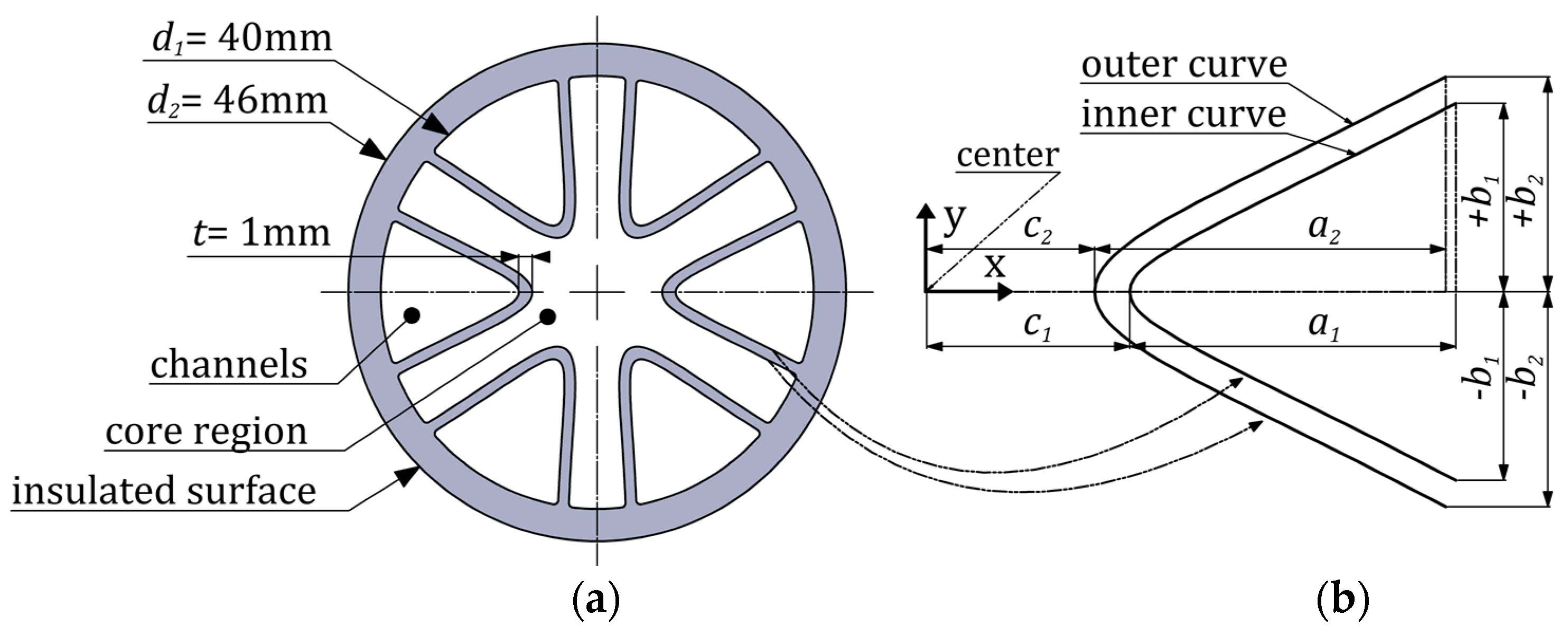
The channel cross-sectional area is determined by integrating the area under the inner curve illustrated in
Figure 1b and defined by Equation (1). To determine the cross-sectional area of the core region, the integrated area under the outer curve should be subtracted from the inner tube area, as discussed in
Section 4.2. The dimensions of the investigated ICT heat exchanger are given in
Table 2.
4.1. Set-Up
The experimental unit used for studying the thermal and fluid-dynamic performance of the ICT heat exchanger was located at the Chair of Fluid Process Engineering of Paderborn University. In the experiments carried out under turbulent flow conditions and presented in [
22], a new experimental set-up for the ICT heat exchanger was built. This set-up consisted of various components, such as flowmeters, thermocouples, thermostats, pumps, tanks, and a pair of heat exchangers to regulate inlet temperatures. An additional heat exchanger was employed to generate hot water for the ICT by using steam from a steam generator. The flow rates, temperatures, and pressure drop were all monitored and recorded using the LabVIEW interface. In this work, the experimental set-up established in the previous study [
22] was used to investigate laminar flow conditions. An adjustment was made by replacing the flowmeters with those featuring a lower flow range. Additionally, the design of the thermocouples for the bulk temperature measurements within the core region flow was reconsidered to better fit laminar flow conditions.
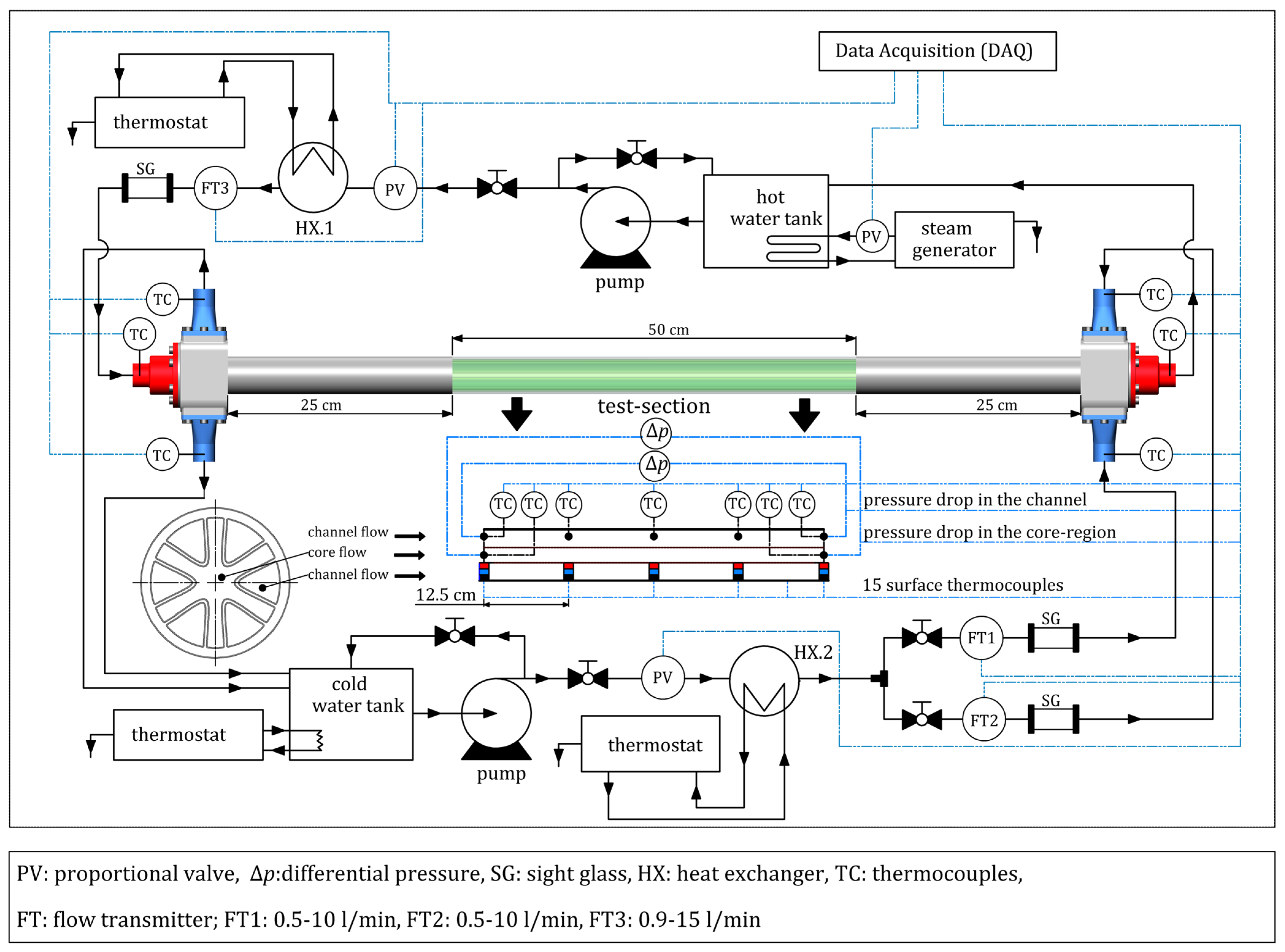
The experimental setup comprised four loops, two for cold/hot fluids and two for regulating the inlet temperatures by utilizing two heat exchangers, as shown in
Figure 5. The flow of the cold fluid is pumped to the channels, while that of the hot fluid is supplied to the core region of the ICT. This arrangement enables the establishment of a counter-current flow pattern since the hot and cold fluids move in different directions.
The vortex flowmeters, with a flow range of 0.5 to 10 L/min, regulate the cold fluid pumped to the ICT through the two inlets (cf.
Figure 5). Three channels of the ICT are supplied with cold fluid from each inlet port, ensuring that all six channels are covered. At the entrance of the left side header, a flowmeter calibrated for a flow range between 0.9 and 15 L/min regulates the flow of the hot fluid (see
Figure 5). Each flowmeter has a precision within the range of ±0.5% relative to its full scale. The facility unit is provided with two Rosemount 3051 differential pressure sensors employed for measuring pressure drop in the middle section of the ICT ducts (
Figure 5, “test section”). One transmitter is installed at the core region, whereas the other is placed in one of the ICT channels, assuming that flow is identical in all channels. Each differential pressure sensor has a range of 0–10 mbar, and an accuracy of ±0.2% of the set span.
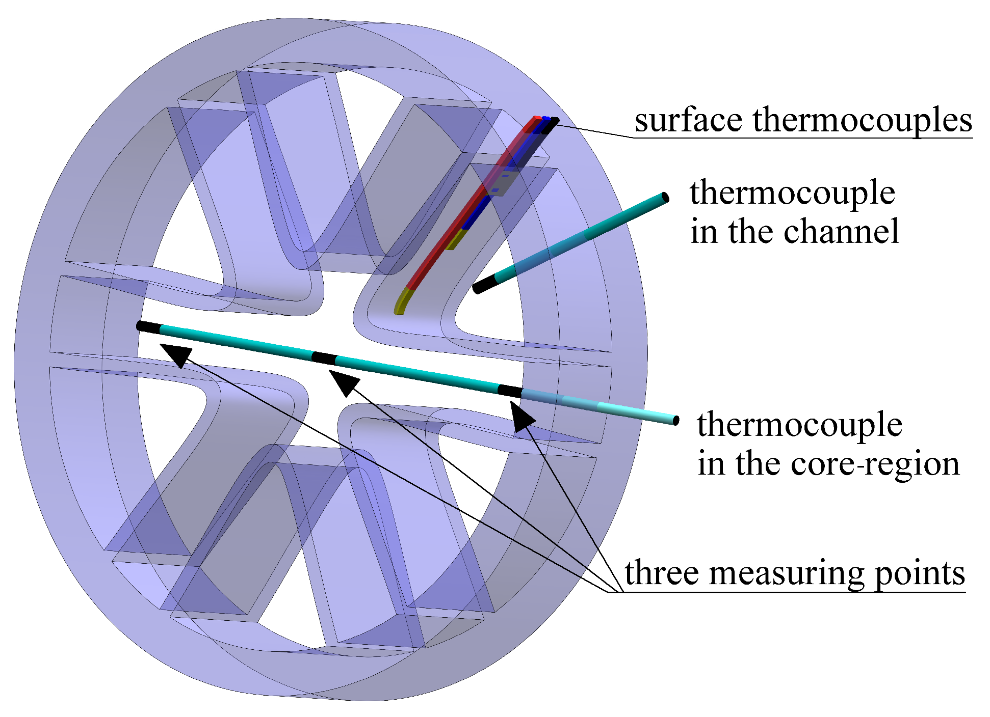
Thermocouples are used for direct measurement of the bulk temperatures of hot/cold fluids at the inlet/outlet header ports and along the test section length (see
Figure 5). As explained in [
22], surface thermocouples were mounted on the interior channel wall with great care, specifically within a milled groove that was sealed with thermal adhesive to avoid any fluid flow obstruction that could influence wall temperature measurements. Fifteen surface thermocouples were used to measure the wall temperature. They were fixed at five positions on the channel surface along the test section, with a longitudinal distance of 12.5 cm (cf.
Figure 5). Additionally, three surface thermocouples were placed at each longitudinal position to measure the temperature distribution along the internal curved surface of the ICT channel (cf. [
22]). Each thermocouple used was of type K and calibrated in the laboratory using standard thermometers with an accuracy of ±0.5 °C. To minimize heat loss into the surrounding area, the full exterior surface of the ICT was covered with 3 layers of insulation, consisting of rubber and fibrous materials. The estimated critical thickness of insulation was approximately 3 mm, based on the hot fluid flowing in the core region. Furthermore, the experimental unit contains variable electric and mechanical valves to regulate the fluid that flows through the flow meters as well as to control preheating and cooling processes.
The uncertainty in the measured pressure drop and temperatures was estimated by combining bias error and standard random deviation, with the latter calculated based on the approach outlined in [
32]. The specific bias errors of the used equipment are mentioned above. Furthermore, calibrations were employed to minimize the systematic uncertainties in temperature, pressure, and flow measurements. In thermocouples, errors, such as wire resistance, are minimized through calibration. Additionally, the use of appropriate attachment methods and special adhesives such as thermal epoxy resin helped to reduce errors that may have arisen from the displacement of the hot junction from its position. Overall uncertainties, at a 95% confidence level, were found to be approximately ±4% for pressure drop and ±1.5 °C for temperatures.
4.2. Operating Conditions and Process Parameters
The experiments under laminar flow conditions were performed with inlet temperatures set at 20 °C for the cold fluid and 50 °C for the hot fluid. The Reynolds number was varying from 1000 to 2000 in the core region and channels. The Reynolds number for the flow within the ICT ducts is defined based on hydraulic diameter:
Here,
is the mass flow rate,
μ is the dynamic viscosity of the fluid,
Acs represents the cross-sectional area of the ICT duct, and
Dh is the hydraulic diameter. The latter is defined as four times the cross-sectional area of the duct divided by its wetted perimeter:
Here,
Ph is the hydraulic or wetted perimeter of ICT ducts.
Acs is either the cross-sectional area of the core region (
Acr), or of the channel (
Ach). The channel cross-sectional area is calculated by numerical integration according to the following equation:
with
defined by Equation (1) and the integration domain specified in
Table 1 (−
b ≤
y ≤ +
b) [
21,
23].
For the core region,
Acr is determined by subtracting the total area enclosed by the outer curves from the area of the inner tube as follows:
while the area under the outer curve is calculated as follows:
The hydraulic or wetted perimeter (
Ph) of each channel duct is determined by
and for the core region as follows:
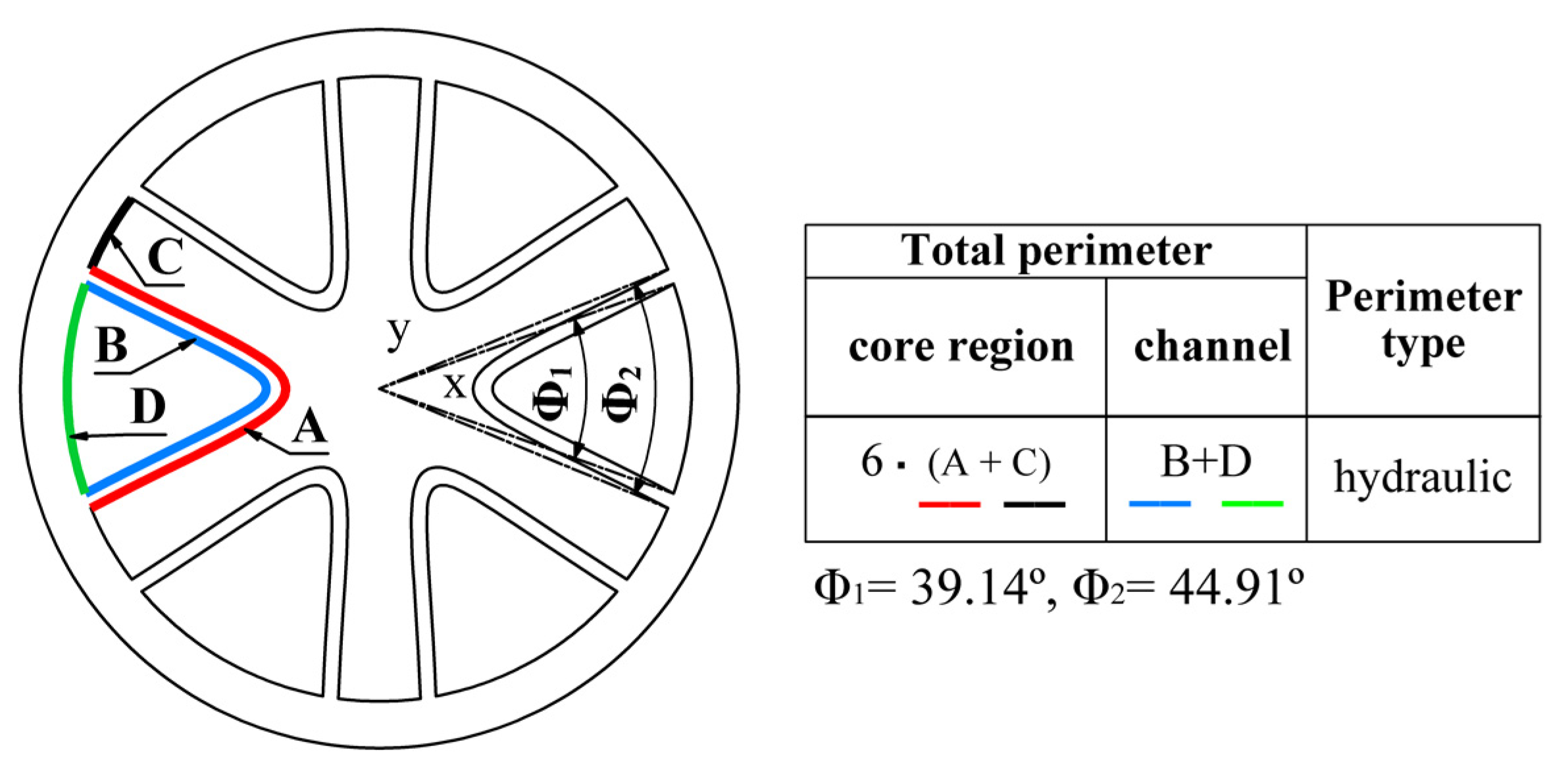
The quantities Φ
1 and Φ
2 are illustrated in
Figure 6. The table in this figure gives explanations for the lengths of the hydraulic perimeters.
Water was selected as the process medium for the channel ducts of the ICT. In the core region, the sensible frictional pressure drop is relatively low at small Reynolds numbers. In order to increase the recorded pressure values, it became essential to increase the flow rate, ensuring accurate measurements and minimizing uncertainties. Therefore, a mixture of water and glycerin was used as the working fluid in the core region to augment the viscosity of the hot fluid. This adjustment facilitated the attainment of laminar flow conditions with higher flow rates at the same given Reynolds numbers in the core region. The volume fraction of glycerin was 26%. The properties of the fluids are given in
Table 3. The viscosity of the water–glycerin mixture at the specified volume fraction and temperature was determined in the laboratory through the utilization of a rotational viscometer. Other mixture properties were obtained from [
33,
34].
A steady state is assumed to be achieved once the pressure drop, temperature, and flow rate of both fluids remain constant for a minimum of 60 min. The targeted temperature and flow rate are maintained, and a data acquisition system based on LabVIEW consistently captures wall temperatures, fluid inlet/outlet temperatures, and pressure drop in the test section. After reaching a steady-state condition, 500 measuring points (temperature, pressure drop, and flow rate) were captured.
5. Maldistribution in the Channels
The experimental studies of ICT heat exchangers began with an evaluation of maldistribution in channel flow. Maldistribution occurs when fluid flow is unevenly distributed in either one or both branches of a heat exchanger. This irregular distribution may adversely impact the overall performance of the heat exchanger, leading to a significant reduction in its efficiency [
35]. The maldistribution in the ICT was specifically evaluated for the fluid flow in the channels. This is because each inlet in the header, illustrated in
Figure 5 and
Figure 7, distributes water between three ICT channels (cf.
Section 4.1). The header, shown in
Figure 7, is supplied with a pair of guide blades at each port. These blades enable the flow to be distributed equally between the three channels. Preliminary CFD simulations were utilized to optimize the guide blades. The optimization included a modification of both the leading edge and blade profile as well as an adjustment of the gap size between the blades (cf.
Figure 7).
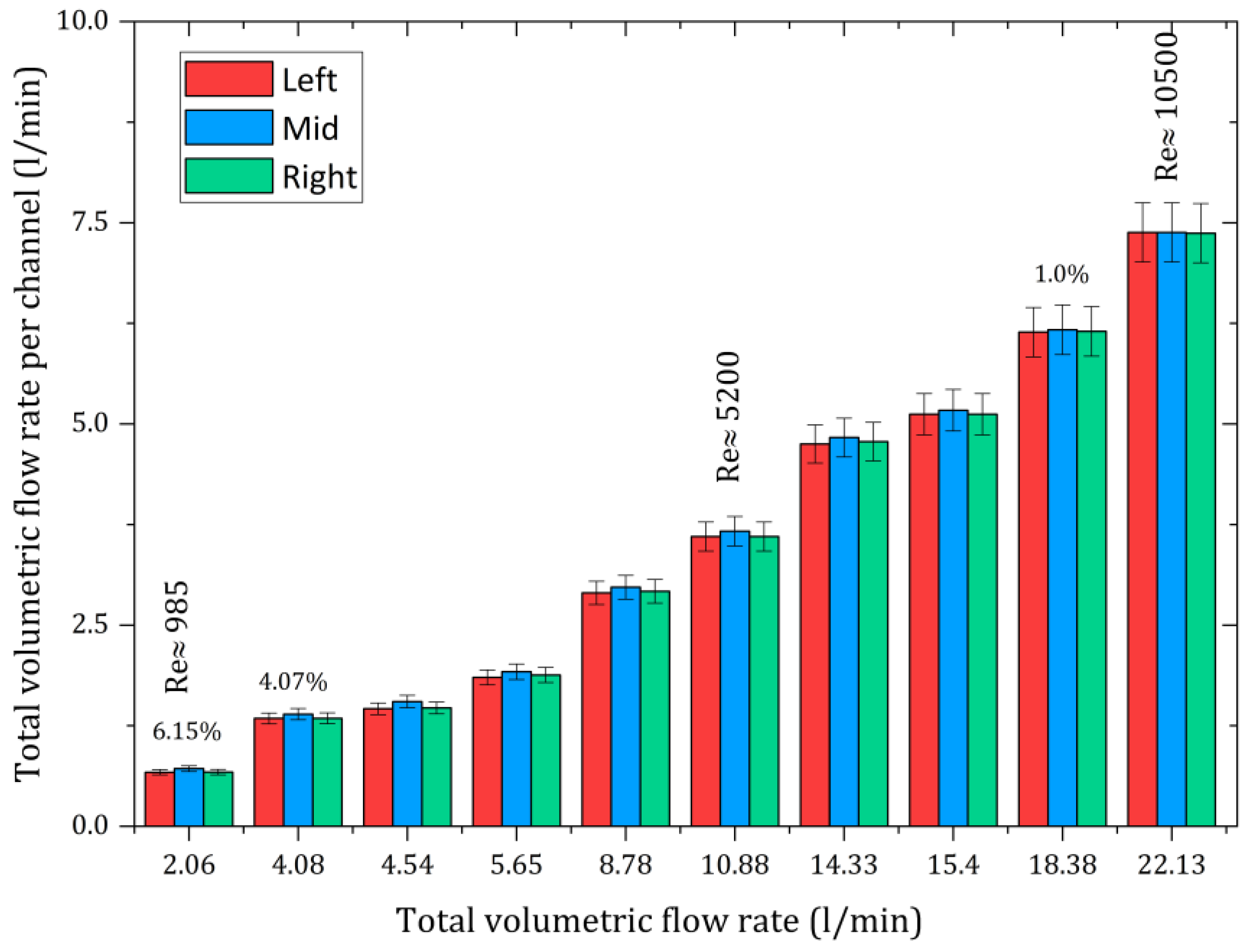
Figure 8 shows the experimentally measured volumetric flow rates in the ICT channels. Full details of the experimental set-up and the maldistribution evaluation procedure for the ICT channels can be found in [
22]. The difference in the flow rates is mostly insignificant (1% to 2% higher in the mid-channel). However, at a total flow rate of 4 L/min, the difference increases to up to 4%. Below a Reynolds number of 1000, the difference exceeds 6%, as shown in
Figure 8. In such cases, the highly uneven fluid distribution may cause imbalances that reduce the precision of temperature measurements. This is why very low flow rates are avoided in experiments and a minimum Reynolds number of 1000 is set for the laminar flow in the channels to ensure accurate data.
6. Flow Type Characterization in ICT Ducts
The flow type refers to the specific pattern of fluid motion, which can range from smooth and orderly (laminar) to chaotic and irregular (turbulent) and include several transitional phases in between [
36]. The identification of the dominant flow pattern in a fluid system via experimental means can be performed by various methodologies and techniques. Common ways include the use of flow visualization methods or pressure drop measurements [
37,
38]. Visualization methods provide a qualitative understanding of the flow patterns. They can be realized by introducing tracer particles into the fluid, employing dyes or colored liquids, and utilizing transparent outer walls or pipes to observe the flow [
37]. In the case of the ICT, the feasibility of visualizing the flow within the ducts is hindered by their enclosed structure and missing tube wall transparency.
The second approach is based on pressure measurements in the core region and channels of the ICT. These measurements can then provide valuable flow characteristics for various Reynolds numbers [
38].
Figure 9 illustrates the normalized friction factor (
) plotted against the Reynolds number. The Fanning friction factor is determined as follows:
where Δ
p is the difference between the measured pressure values at the inlet and outlet boundaries of the test section.
um is the mean velocity, and
l is the length of the test section. The calculated friction factor values are normalized using the corresponding maximum value
fmax. The latter is obtained based on the measured pressure drop in the core region and channel at Reynolds numbers of 2000 and 1500, respectively. According to
Figure 8, the transition flow turns to turbulent flow at Re ≈ 2000 in the core region, whereas the critical Reynolds number—marking the threshold at which laminar flow shifts to transitional flow—is approx. 1800. For the channels, the flow becomes turbulent at Re ≈ 2150; the critical Reynolds number is Re ≈ 2000.
For a Reynolds number below the critical value, laminar conditions dominate. As a result, the friction factor demonstrates an inverse relationship with the Reynolds number, decreasing approximately in a linear fashion as the Reynolds number rises. A transitional flow is characterized by a sudden increase in friction factor due to the emergence of disturbances in the flow. Once the flow is completely turbulent, the friction factor drops again (cf.
Figure 9).
8. Thermal–Hydraulic Performance of the ICT
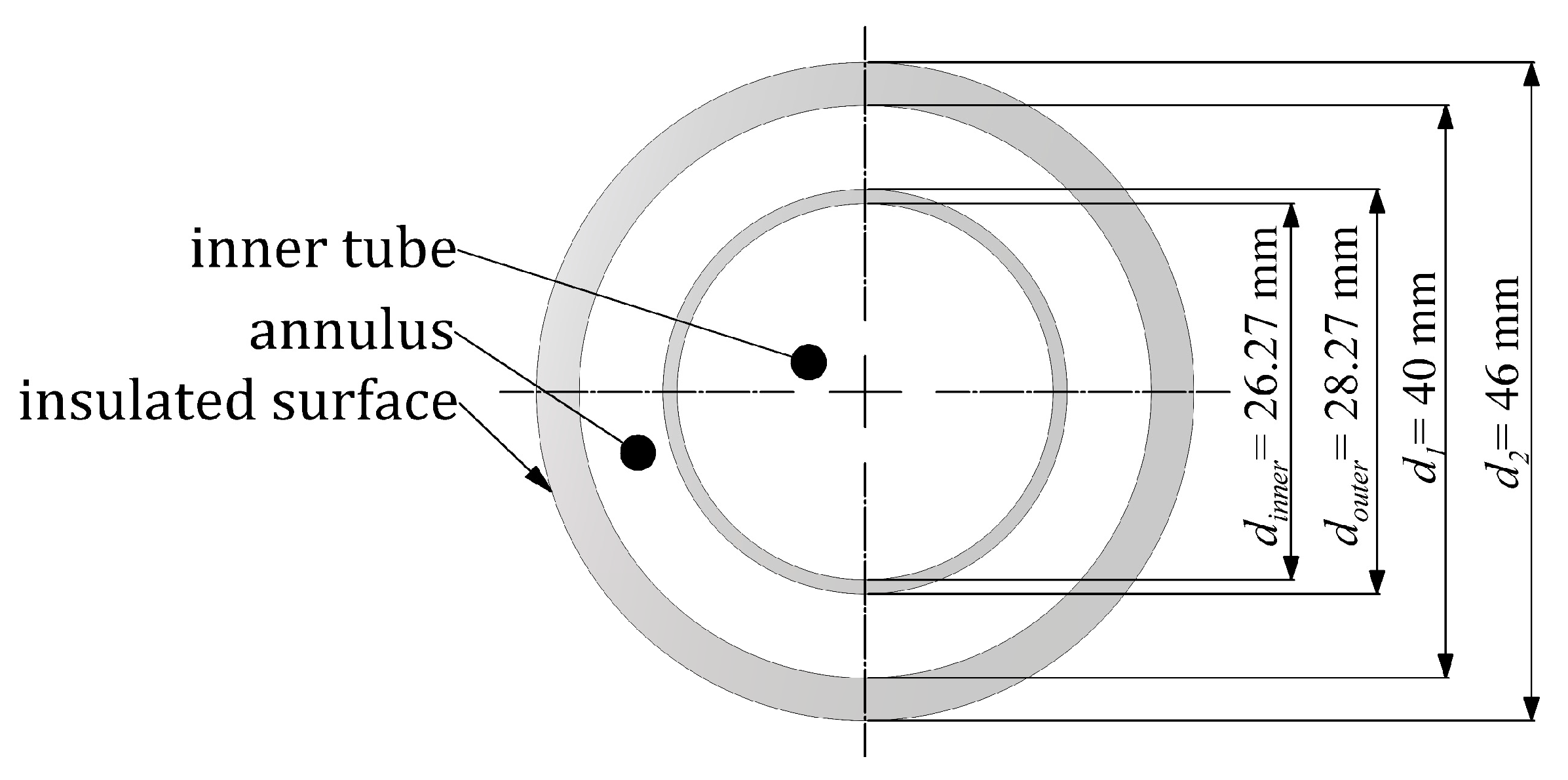
In this study, an evaluation of the thermal–hydraulic performance of the ICT heat exchanger under laminar flow conditions was carried out. This characteristic allows the exchanger’s economic viability to be estimated. The ICT thermal–hydraulic performance was evaluated in comparison with a double-pipe heat exchanger (DPHE). The latter represents a simple and widely used heat exchanger comprising two concentric pipes. The performances of the ICT and DPHE heat exchangers were compared under the following constraints: the same applied mass flow rate (
), identical lengths (
l), diameters (
d1 and
d2), and wall thicknesses (
t) (cf.
Figure 1 and
Figure 14). The ratios of the cross-sectional areas of the cold and hot fluid ducts (
Achannel/
Acore region,
Aannulus/
Ainner pipe) were upheld at a constant value of 1.160 [
21]. Furthermore, the inlet temperatures and properties of both fluids were identical for both ICT and DPHE.
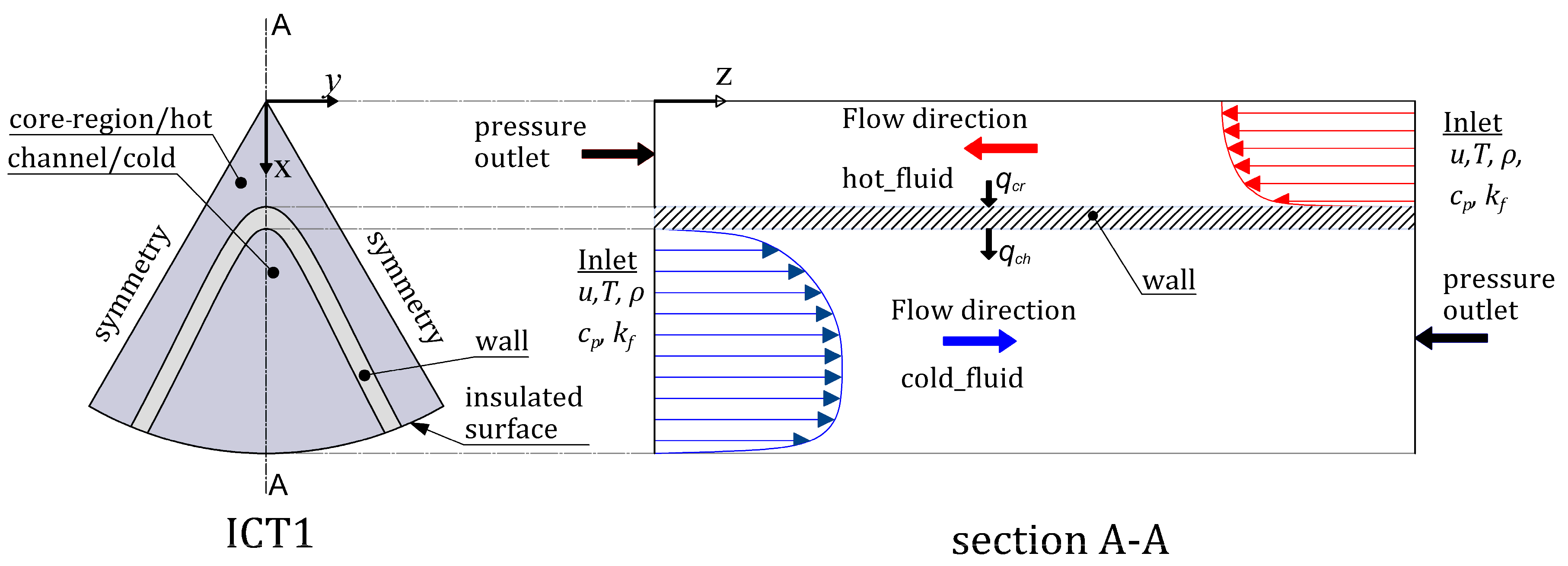
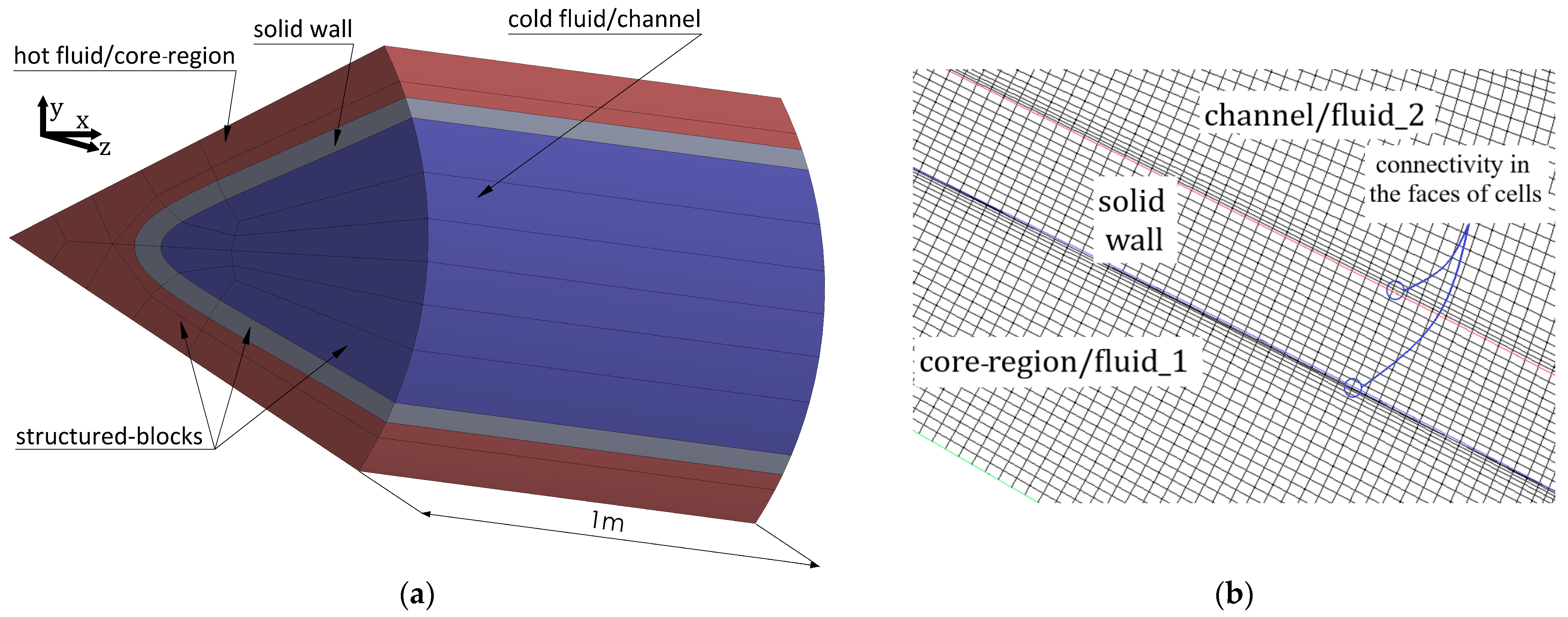
For the thermal–hydraulic evaluation of the ICT, additional simulations were performed, with four cases to cover more practical conditions. They were accomplished at an inlet temperature of 65 °C for the core region (hot side) and 10 °C for channels (cold side) of ICT. Similarly, these temperature values were applied to the inner pipe (hot side) and annulus region (cold side) of the DPHE. Water was chosen as the process medium on both cold and hot sides. The properties of the fluid at these specified temperatures are detailed in
Table 4. The mass flow rates were set in a special way to allow for a reasonable comparison between the two heat exchanger types. With different flow rate relationships, four cases (C1–C4) were specified. In the first case (C1), an identical mass flow rate was used within the core region and in six channels of the ICT. In cases C2, C3, and C4, the mass flow rates in the channels were increased to two, three and four times the rate applied in the core region, respectively. The objective here was to increase the Reynolds number within the channels to reach a value approximately equal to that in the core region. In
Table 5, a summary of the mass flow rates for the four cases under laminar flow conditions is given. Using mass flow rate instead of Reynolds number ensured the consistent application of pumping power values in both the ICT and DPHE ducts. The mass flow rates in the studied cases were applied to the inner pipe and annulus regions of the DPHE in a similar manner as they were applied to the core region and channels of the ICT. We assumed that the inner pipe (representing the hot side) is analogous to the core region of the ICT, while the annular region (representing the cold side) is comparable to the channels.
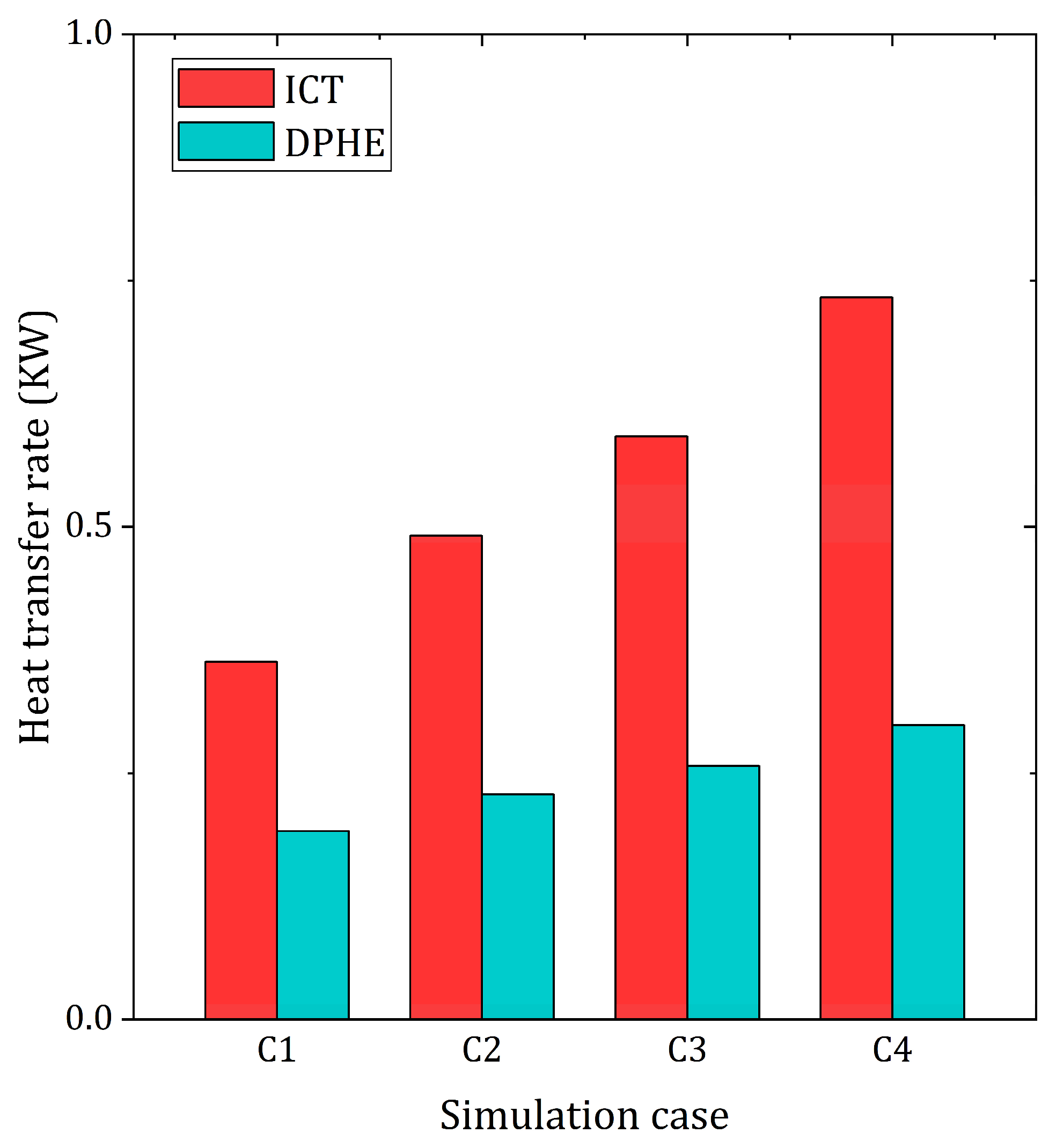
A comparison of the heat transfer rates of the ICT and DPHE heat exchangers is presented in
Figure 15. Heat transfer rate is determined by
Here, ∆T is the temperature difference between the outlet and inlet of the test section, and cp is the specific heat of water.
In
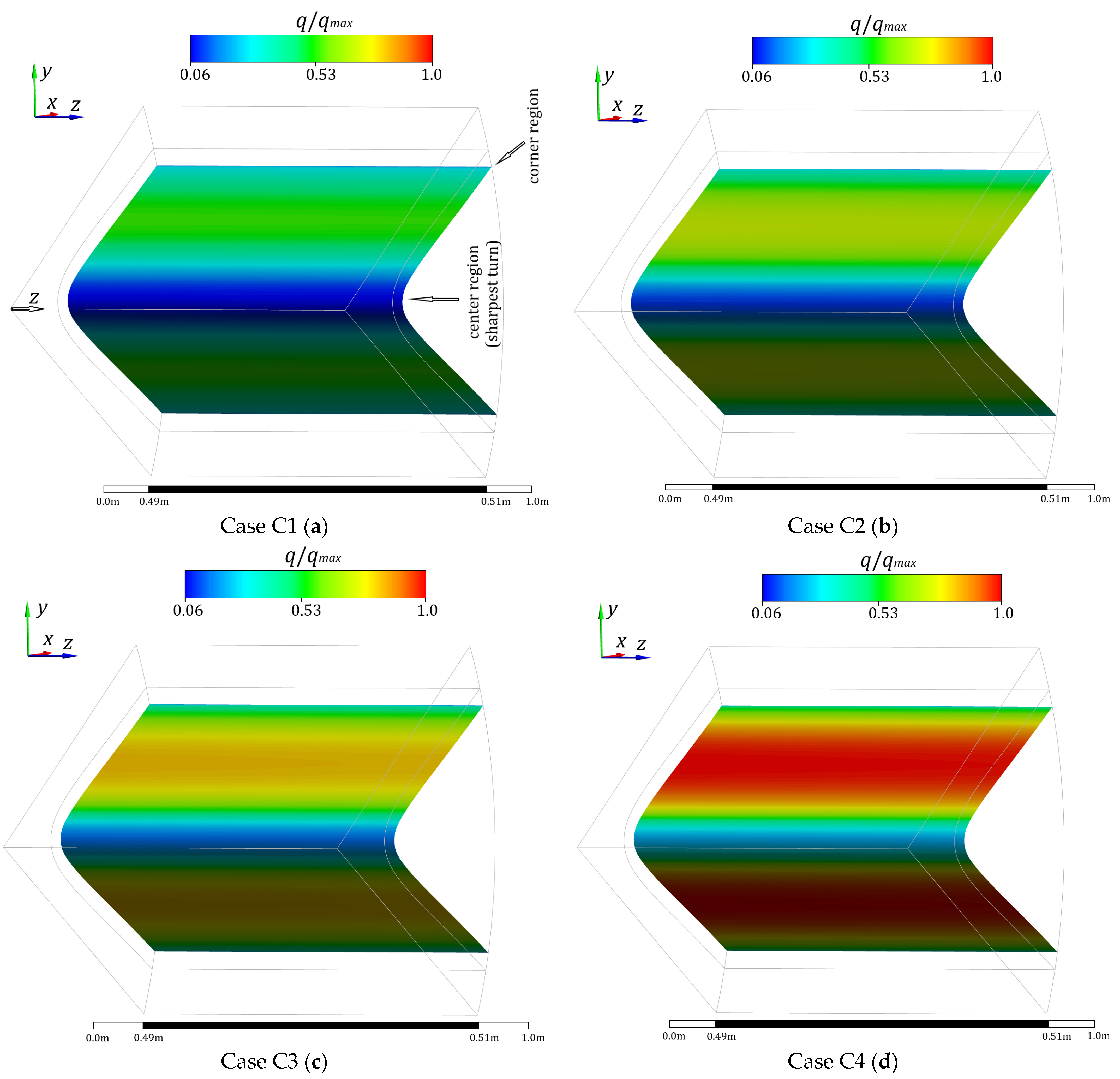
Figure 15, the comparison reveals significantly higher heat transfer rates for the ICT than for the DPHEs, with the enhancement of up to 60%. This enhancement in thermal performance can be attributed to the fact that the heat transfer area between the operating fluids is nearly doubled. The ICT was better in all cases C1 to C4, while the maximum was achieved in case C4. This is clearly visible in the contour plots shown in
Figure 16. This figure exhibits the distribution of local heat flux over the internal channel wall along a segment of 2 cm at the middle of the ICT. The heat flux values are normalized by its maximum obtained value.
According to
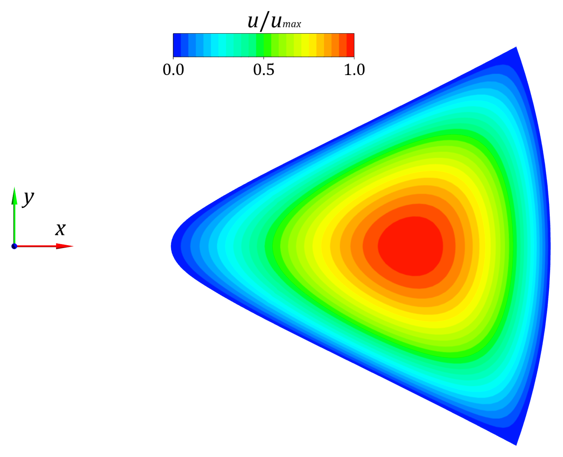
Figure 16, the region of poor heat transfer is clearly marked by a blue area near the center of the tube (sharpest turn of the channel surface) and the corner regions, where separation of the flow from the channel surface may occur. On the other hand, the maximum heat flux is seen in the vicinity of the narrow gaps between the channels. This location indicates where the flow reattaches to the wall, and this is illustrated by the thin hydrodynamic layers in the velocity contour presented in
Figure 17. Our previous study [
23] explored the optimization possibilities of the channel shape using parameters (
a1 and
b1) under turbulent flow conditions. It was found that heat transfer through the channel wall can be enhanced by increasing
b1 while keeping
a1 constant. This improvement takes place because the sharpest turn (i.e., vertex of a parabola) of the channel wall near the tube center becomes somewhat wider, leading to a reduction in the flow separation in this region. Conversely, increasing
a1 while maintaining
b1 constant, narrowing the sharpest turn, leads to worse heat transfer.
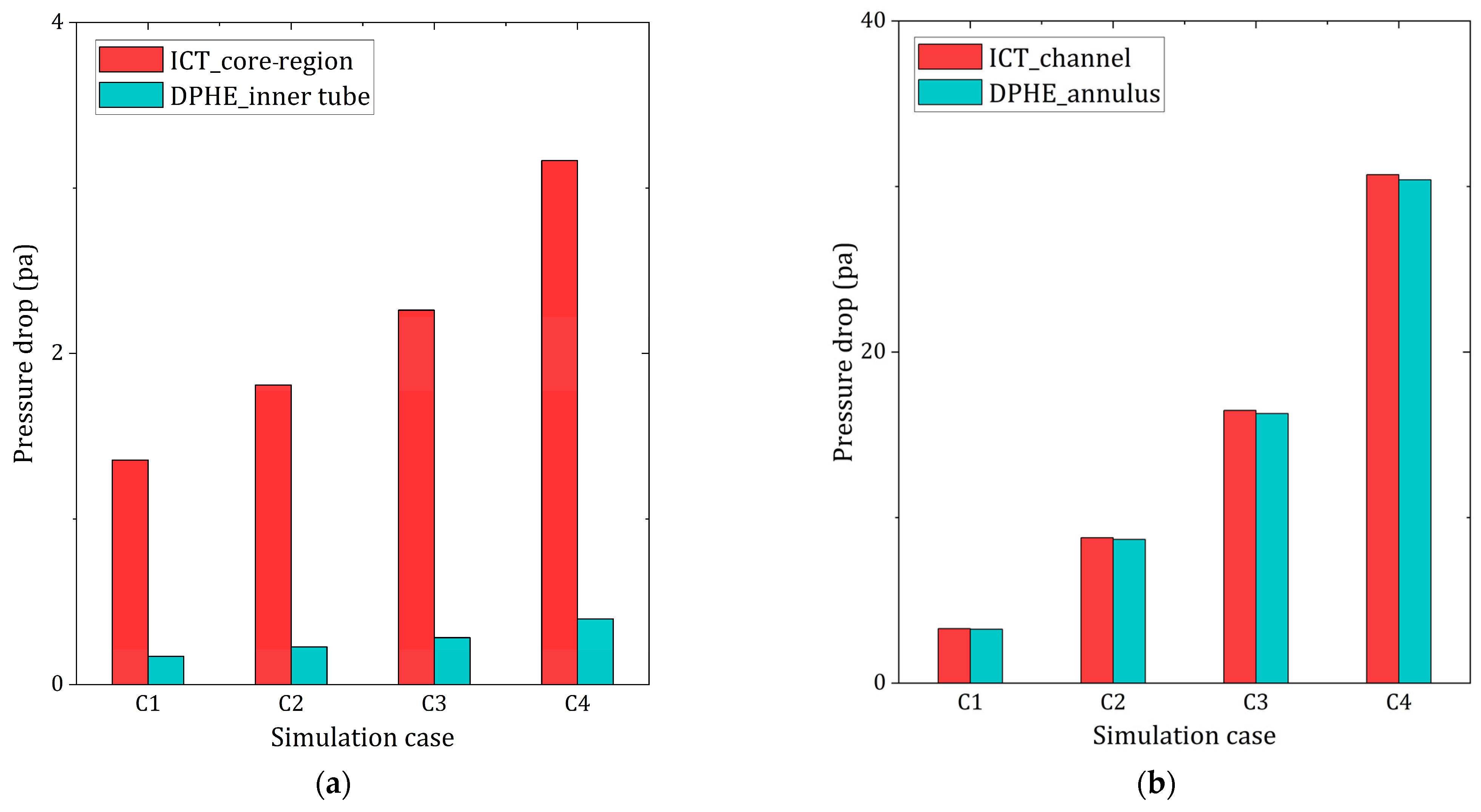
In the comparative study, it was further found that the pressure drop was higher in the ICT than in the DPHE. This was attributed to the larger surface of the ICT internal walls and is to be expected. It is quite common that intensified heat transfer is achieved with a higher pressure drop thus requiring higher pump power [
40]. The pressure drop in the core regions for the ICT is approximately up to 87% higher than that in the inner pipe of the DPHE (cf.
Figure 18a). In contrast, for the channel/annulus flow, this increase is much smaller, approximately 4%, (cf.
Figure 18b).
To evaluate the thermal–hydraulic efficiency of the ICT, we adopted a more practical approach based on the ratio of the total heat exchanged between the core region and channels and the overall pressure drop in these ducts (effectively capturing the total energy expended on pumping power). The efficiency can be expressed by
Here,
Q is heat transfer rate and
is volumetric flow rate. For a more convenient comparison with the DPHE, a performance evaluation criterion (PEC) can be employed, by relating the thermal–hydraulic efficiency (
) of the ICT to the DPHE efficiency. This provides a reasonable indicator allowing a comparison of different heat exchanger types. It is essential that the PEC includes both thermal and hydraulic aspects, i.e., the necessary quantities for real-world applications [
41,
42,
43]. The PEC can be expressed as
where
and
are the average heat transfer rates in the ICT and DPHE, respectively.
is the total pumping power in the core region and channels of the ICT,
is the total pumping power in the inner-pipe and annulus of the DPHE. In case C1, the volumetric flow rate
can be disregarded in Equations (18) and (19) because both ducts of the ICT receive the same mass flow rate (
). Therefore, the fluid density has a minimal impact on the calculated PEC, as demonstrated in Ref. [
21].
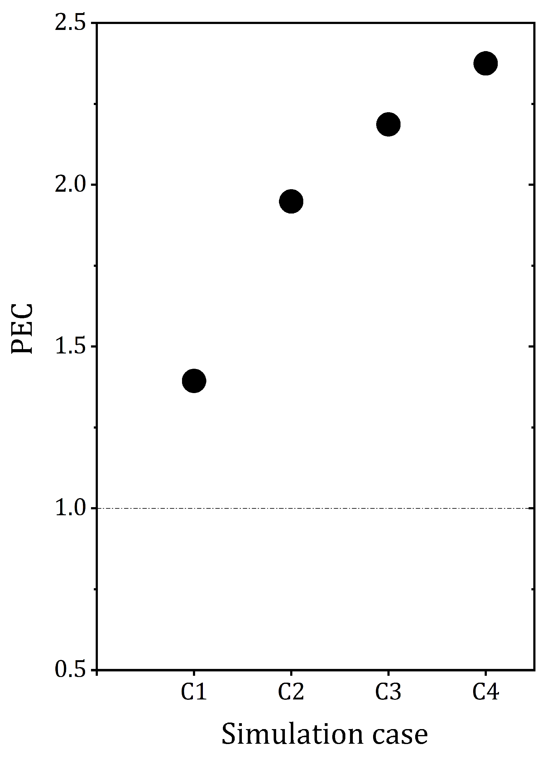
In
Figure 19, the PEC index of the ICT with the DPHE (as the reference exchanger) is shown for the four simulation cases under laminar flow conditions. The PEC values are higher than one, with the highest value reaching nearly 2.3 in case C4. This implies a superior advantage in heat transfer efficiency at an equivalent pumping cost. Based on the PEC values, the increase in heat transfer rate exceeds the rise in pressure drop in the ICT ducts as compared to the DPHE. This result can be explained by a significant increase in the total heat transfer rate of up to 60% exhibited by the ICT (see
Figure 15), accompanied by a minimal pressure drop in the channels (only 4%), as shown in
Figure 18b.
9. Conclusions
In the present paper, a novel heat exchanger design, an internally channeled tube (ICT), was investigated experimentally and numerically under laminar flow conditions. The manufacturing process of the ICT is given, accompanied by a detailed description of the experimental apparatus and measurement methods. The first phase of this experiment included evaluating the maldistribution in the channels and characterizing the flow type within the ICT ducts. At a Reynolds numbers below 1000, a higher flow rate was observed in the middle channel, with a difference exceeding 6%. To ensure accurate measurements, the minimum Reynolds number used in the channels was 1000.
The flow type in the ICT duct was determined through a subsequent experiment by tracking the pressure drop along the test section. Laminar flow behavior was observed in ICT ducts up to a Reynolds number of around 1800 in the core region and 2000 in the channels.
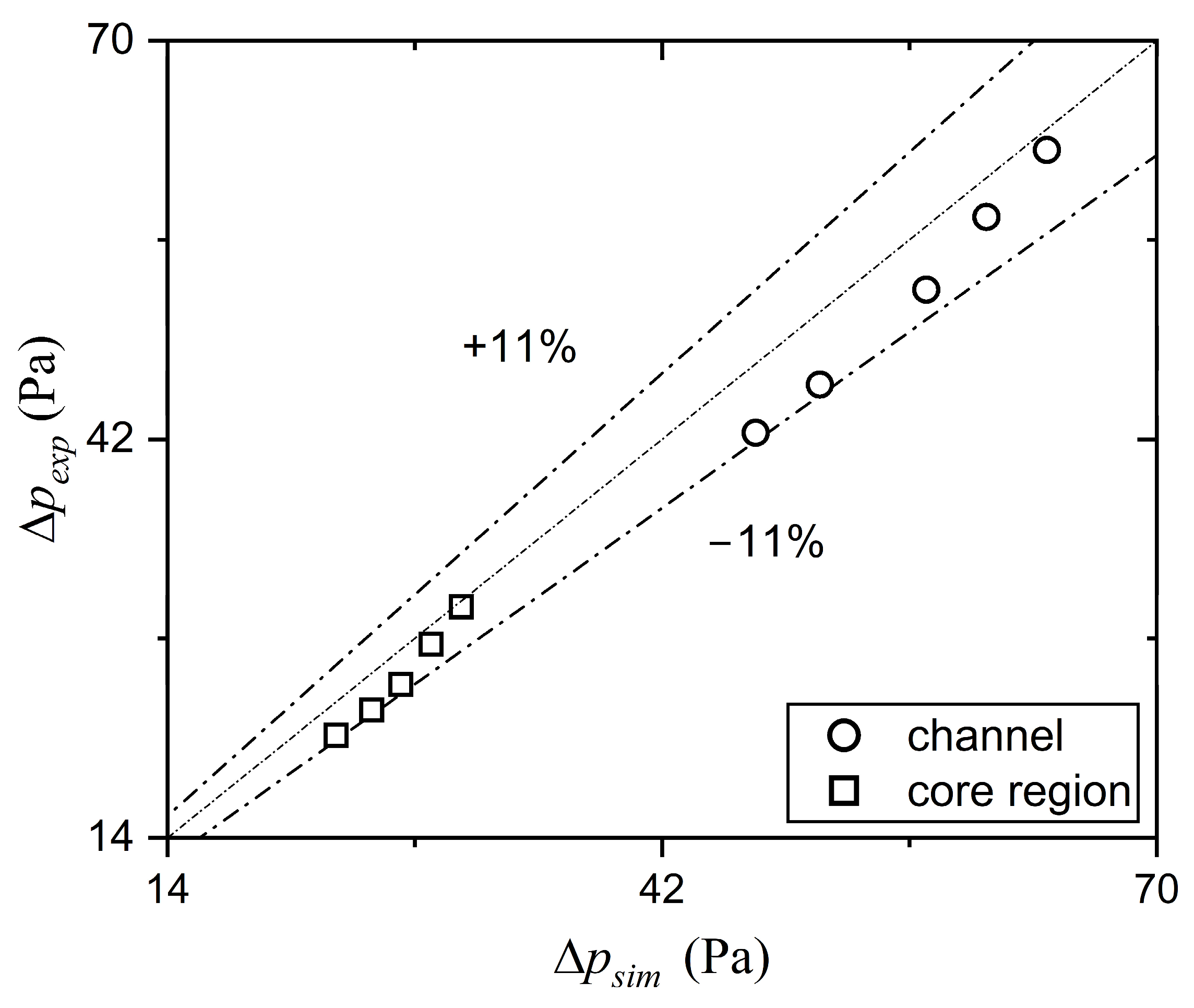
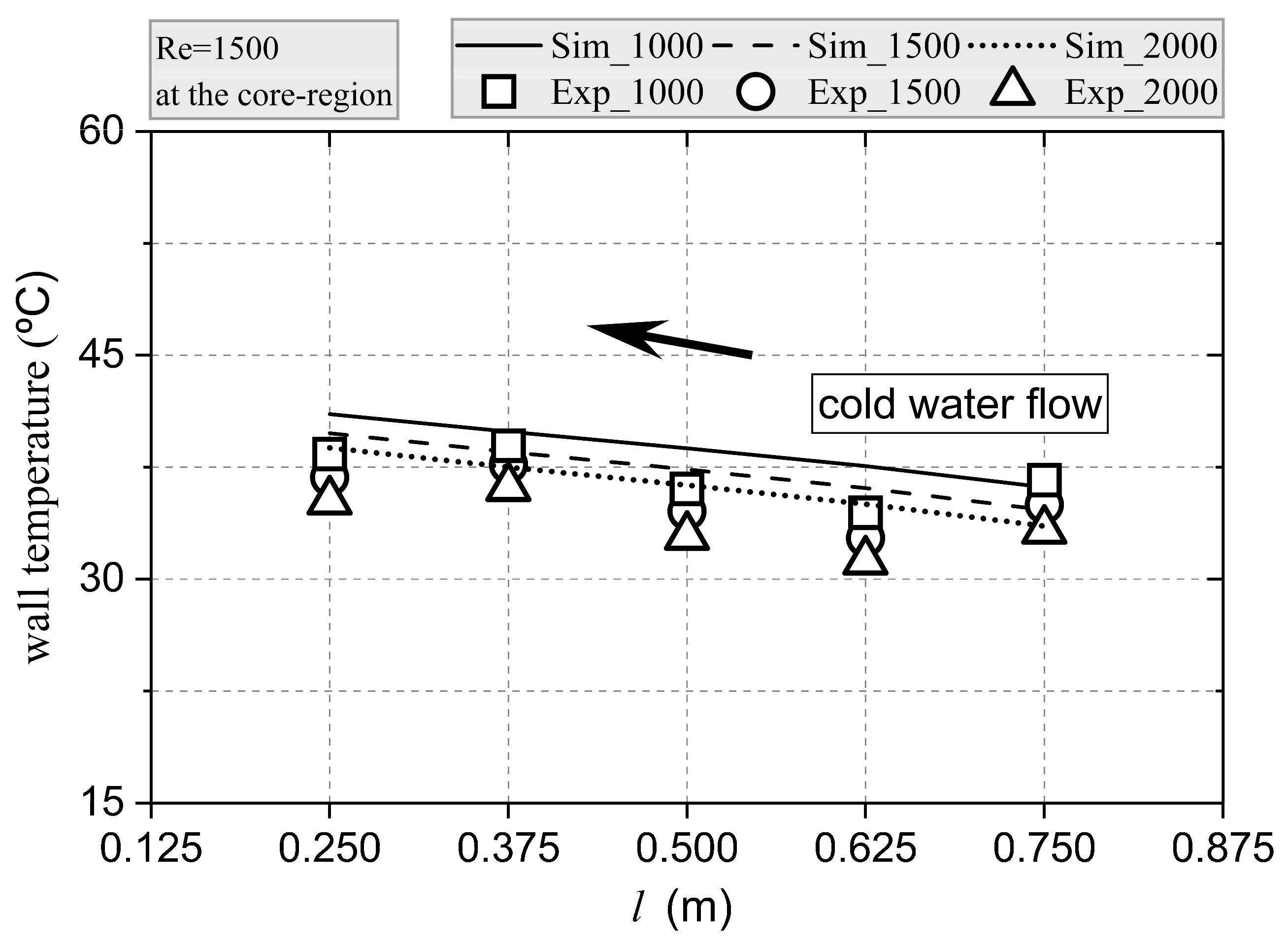
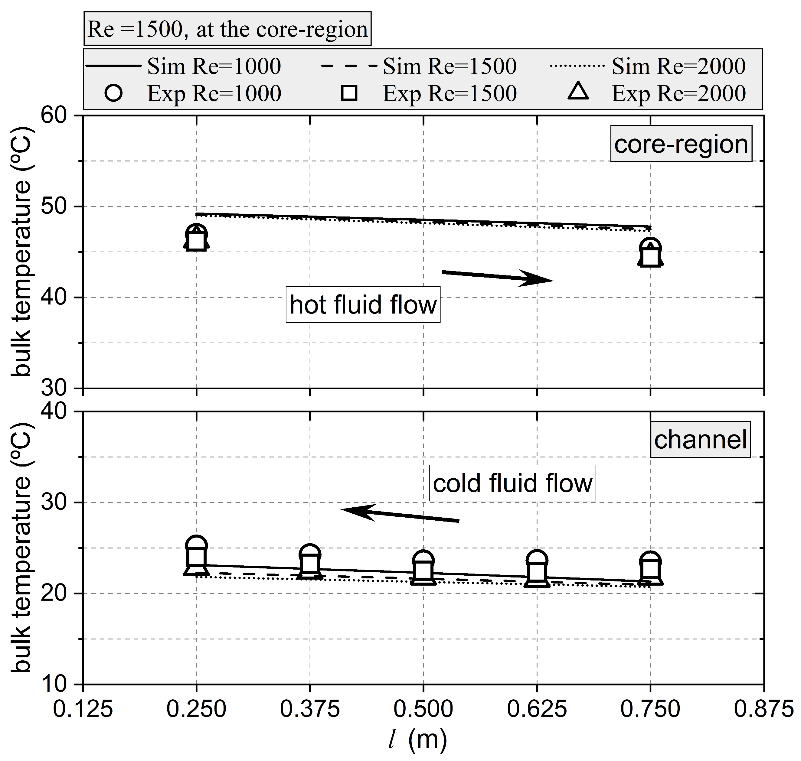
Simulations performed under laminar conditions were validated using the measured values of the pressure drop and temperatures. In both the core region and the channels of the ICT, the maximum deviation between the measured and simulated pressure drop values was 11%, while for the temperatures, the average deviation was below 8%.
Finally, a numerical study was conducted to evaluate the thermal–hydraulic performance of ICT heat exchangers under laminar flow conditions. A comparative study with double pipe heat exchangers (DPHE) under specific constraints revealed significant heat transfer rate enhancement in the ICT. Furthermore, a performance evaluation criterion (PEC) was used to compare the thermal–hydraulic efficiency of the ICT with that of the DPHE. The PEC value was found to be over one, indicating the superior heat transfer efficiency of the ICT at comparable pumping power expenses.
Overall, this study, combining experimental measurements and numerical simulations, provides important data on ICT performance that will permit their application under laminar flow conditions.
