Article

Research on Sliding Mode Variable Structure Model Reference Adaptive System Speed Identification of Bearingless Induction Motor

by
Wenshao Bu
*,
Wenqing Tao
and
Youpeng Chen
Information Engineering College, Henan University of Science and Technology, Luoyang 471023, China
*
Author to whom correspondence should be addressed.
Energies 2024, 17(11), 2615; https://doi.org/10.3390/en17112615
Submission received: 16 April 2024 / Revised: 19 May 2024 / Accepted: 25 May 2024 / Published: 29 May 2024

Abstract

:
To improve the speed observation accuracy of the bearingless induction motor (BL-IM) and achieve its high-performance speed sensorless control, an improved sliding mode variable structure model reference adaptive system speed identification method based on sigmoid function (sigmoid-VS-MRAS) is proposed. Firstly, to overcome the problem of initial values and cumulative errors in the pure integration link of the reference flux-linkage voltage model, the rotor flux-linkage reference voltage model has been improved by using an equivalent integrator instead of the pure integration link. Then, in order to improve the rapidity and robustness of speed identification, the sliding mode variable structure adaptive law is adopted instead of the PI adaptive law. In addition, in order to optimize the sliding mode variable structure adaptive law and overcome the sliding mode chattering problem, a sigmoid function with smooth continuity characteristics is used instead of the sign function. Finally, on the basis of the inverse system decoupling control of a BL-IM, simulation experiments were conducted to verify the sigmoid-VS-MRAS speed identification method. The research results indicate that when the proposed speed identification method is adopted, not only higher identification accuracy and rapidity can be achieved than traditional PI-MRAS methods, but it can also eliminate the problem of high-frequency vibration (with an amplitude of about 3.0 r/min) when using the sign-VS-MRAS method; meanwhile, the steady-state tracking speed with zero deviation can still be maintained after loading.

1. Introduction

Magnetic bearings have been widely used for high-speed motor rotor support [1]. However, motors supported by magnetic bearings still have a series of drawbacks, such as the high-power consumption of magnetic levitation and difficulty in overspeed [2,3,4]. The bearingless motor is a new type of motor proposed based on the stator structure similarity between magnetic bearings and ordinary AC motors, which is suitable for high-speed rotational drive [2,3]. Compared to motors supported by magnetic bearing, bearingless motors have a series of advantages, such as short shaft, high critical speed, and suitability for long-term high-speed operation. Bearingless control technology can be used for various AC motors [4,5,6,7,8]. Among many types of bearingless motors, bearingless induction motors have broad research and application prospects due to their advantages, such as their robust structure and ease of weak magnetic field acceleration [3,9,10,11].
In order to achieve good operational control performance for bearingless motors, it is necessary to monitor and control the speed in real time. Mechanical speed sensors have difficulties in installation and are prone to environmental interference, which is not conducive to the development of bearingless motors in high-speed and ultra-high-speed directions. Therefore, speed sensorless control technology has become one of the research hotspots in the field of bearingless motors [3,9,10,11,12,13]. Among the commonly used speed identification methods, the direct estimation method is simple and easy to implement, but it is greatly influenced by motor parameters. Based on a combination of neural network and fractional order sliding mode, reference [10] proposed a speed observation scheme for a bearingless induction motor, which successfully achieved speed observation. Due to hardware performance limitations and algorithm complexity, artificial intelligence methods still have a certain distance from practical applications. The extended Kalman filter method can work stably over a wide speed range, but its algorithm is complex and requires debugging with a large number of random parameters. Reference [14] uses standard interpolation formulas to reduce model errors and employs iterative loops to improve the accuracy of the filter. Based on this, a speed sensorless control strategy based on iterative center difference Kalman filter is proposed, which achieves good speed tracking performance. Reference [15] introduces control methods into extended Kalman filters and combines robust Kalman filters with model reference adaptive systems to obtain an improved robust Kalman filter; then, a speed sensorless control strategy based on the improved robust Kalman filter is proposed, which can effectively improve the accuracy of speed identification. The high-frequency signal injection method can improve the low-speed observation performance, but it requires the motor to have a certain degree of salient polarity, and the signal extraction algorithm is complex. In reference [16], a pseudo-random signal injection method was studied, which can obtain continuous spectra and significantly suppress electromagnetic and acoustic noise.
The model reference adaptive system (MRAS) method has the advantages of a simple algorithm and easy implementation. In reference [17], based on magnetic flux error, a fractional order MRAS adaptive law was designed to accelerate the response speed of the controlled object; fuzzy control rules were used to online adjust the PI parameters of adaptive law, then a fuzzy PI fractional order MRAS speed identification method is proposed, and the sensorless control of a bearingless asynchronous motors was achieved. While the MRAS speed identification method usually uses the voltage model of the rotor flux-linkage as the reference model, the existing pure integration link has the initial integration value and cumulative error problems, which reduces the accuracy of speed identification, especially in the low-speed stage. The speed observer based on sliding mode variable structure control theory has the advantages of fast response speed and strong robustness to system parameter changes [7,18]. However, the commonly used symbol function can cause chattering phenomena and bring higher harmonic effects to the identified speed. For bearingless induction motors, reference [19] proposed a speed sensorless control strategy that combines an improved sliding mode observer and a phase-locked loop. The dual boundary layer structure switch function is used to reduce high-frequency jitter, and the speed is extracted from the observed magnetic flux components.
In this paper, the bearingless induction motor (BL-IM) is taken as an object; in order to improve the accuracy and rapidity of speed identification, a sliding mode variable structure MRAS speed identification strategy is proposed. This paper first improves the rotor flux-linkage reference voltage model, combines the sliding mode variable structure idea with the MRAS method, and proposes a variable structure MRAS speed observation method based on the sigmoid function, namely the “sigmoid-VS-MRAS” method. Finally, on the basis of an inverse decoupling control system of a BL-IM, a detailed simulation experiment was conducted to verify the proposed method. The research results indicate that when using the proposed sigmoid-VS-MRAS speed identification method for a BL-IM system, not only can higher speed identification accuracy, rapidity, and resistance to load torque disturbances be achieved compared to traditional PI-MRAS methods, but also the high-frequency vibration problem when using the sign-VS-MRAS method can be eliminated; thus, it provides convenient conditions not only for the implementation of high-precision sensorless technology of BL-IM but also for the low-cost of the system. The flowchart of the research method in this article is shown in Figure 1.

2. VS-MRAS Speed Identification Method

2.1. Improvement of Rotor Flux-Linkage Model for MRAS Speed Identifier

According to the mathematical model of BL-IM [9], under the α-β stationary two-phase coordinate system, the voltage- and current-models of rotor flux-linkage can be written as follows:
ψ r 1 α = L r 1 L m 1 u s 1 α R s 1 + σ L s 1 p i s 1 α d t ψ r 1 β = L r 1 L m 1 u s 1 β R s 1 + σ L s 1 p i s 1 β d t
p ψ r 1 α = L m 1 T r 1 i s 1 α ω r ψ r 1 β 1 T r 1 ψ r 1 α p ψ r 1 β = L m 1 T r 1 i s 1 β + ω r ψ r 1 α 1 T r 1 ψ r 1 β
where ψr1α and ψr1β are the α-axis and β-axis components of rotor flux-linkage, respectively; us1α and us are the α-axis and β-axis components of stator voltage, respectively; is1α and is1β are the α-axis and β-axis components of stator current, respectively; Rs1 and Rr1 are the stator resistance and rotor resistance; Ls1 and Lr1, Lm1 are the stator self-inductance, rotor self-inductance and mutual inductance, respectively; ωr is rotational angular velocity; Tr1 is rotor time constant, Tr1 = Lr1/Rr1; σ is leakage inductance coefficient, σ = 1 L m 1 2 / L s 1 L r 1 ; p is differential operator.
As a mechanical variable, the speed can be approximated as a fixed value within a sampling period. Based on the idea of MRAS speed identification and from the rotor flux-linkage current model in Equation (2), an adjustable model of the rotor flux-linkage is constructed as follows:
p ψ ^ r 1 α = L m 1 T r 1 i s 1 α ω ^ r ψ ^ r 1 β 1 T r 1 ψ ^ r 1 α p ψ ^ r 1 β = L m 1 T r 1 i s 1 β + ω ^ r ψ ^ r 1 α 1 T r 1 ψ ^ r 1 β
where the variable with the symbol “^” represents the observed or identified value of the corresponding variable.
The voltage model of the rotor flux-linkage is used as the reference model, but due to the pure integration link in it, the initial value and cumulative error of the integrator will affect the observation accuracy of the rotor flux-linkage, thereby reducing the identification accuracy of the speed [12]. To solve this problem, so as to improve the pure integration link, a first-order inertial link is used to replace the pure integration link equivalently, and its output signal is compensated using a low-pass filter. In this way, the first-order inertial link and the compensation link of the output signal together form an equivalent integration link. The specific input–output relationship can be expressed as:
y = x s + ω c + ω c k s + ω c
where y is the output variable of the integrator after compensation, x is the input variable of the integrator, k is the compensation signal, ωc represents the cutoff frequency of the system, and s is the Laplace operator.
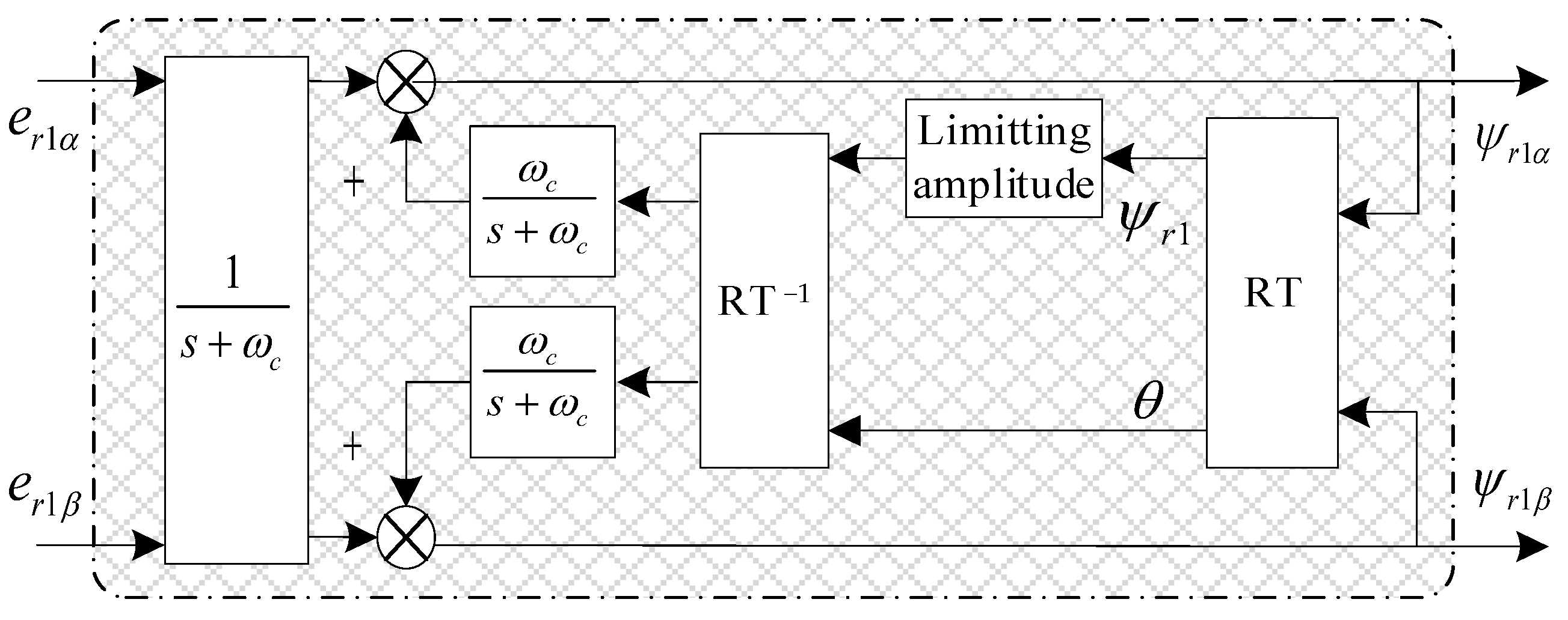
By adjusting the compensation signal k, the performance of the improved equivalent integration link can be between the pure integration link and the first-order inertia link. Here, the compensation signal k is selected as y, and Equation (4) is equivalent to a pure integration link. Taking the relationship between the induced electromotive force of the rotor winding and the rotor flux-linage as an example, Figure 2 shows the schematic diagram of the improved rotor flux-linkage voltage model.
In Figure 2, RT represents the coordinate transformation from rectangular coordinate system to polar coordinate system, and RT−1 is its inverse coordinate transformation; the limiting amplitude of the output rotor flux-linkage is determined based on the rotor flux-linkage at the rated state of a BL-IM, which can be calculated based on the rated voltage and rated frequency. The er1α and er1β are the α- and β-axis components of the induced electromotive force in the rotor windings; their expressions can be obtained from Equation (1) as follows:
e r 1 α = L r 1 L m 1 u s 1 α R s 1 + σ L s 1 p i s 1 α e r 1 β = L r 1 L m 1 u s 1 β R s 1 + σ L s 1 p i s 1 β
The selected error function is “ ε = ψ r 1 β ψ ^ r 1 α ψ r 1 α ψ ^ r 1 β ”. Then, when the speed is MRAS identified based on the rotor flux-linkage from the Popov super stability theory, the speed PI adaptive law can be constructed as follows:
ω ^ r = k p + k i p ψ r 1 β ψ ^ r 1 α ψ r 1 α ψ ^ r 1 β
where ψ ^ r 1 α and ψ ^ r 1 β are obtained from the current model of rotor flux-linkage in Equation (3), and ψ r 1 α and ψ r 1 β are obtained from the improved rotor flux-linkage voltage model. Regarding the selected error function, rationality has been proven and widely used in the MRAS speed identification system [20].

2.2. VS-MRAS Speed Identification

Since the PI adaptive law cannot meet the fast and robust requirements of speed identification, this paper adopts sliding mode variable structure adaptive control law on the basis of the MRAS method; thus, a new speed observation method based on the variable structure–model reference adaptive system (VS-MRAS) is proposed.

2.2.1. Sliding Mode Variable Structure Idea

The basic idea of sliding mode variable structure control is to switch the structure of the controller in real-time based on the “polarity of state deviation” to achieve certain control performance requirements [9]. The controller form can be expressed as follows:
u = u + x S x > 0 u x S x < 0
where u + ( x ) u ( x ) ; S ( x ) is the switching function of sliding mode surface; “ S ( x ) = 0 ” is switch hyperplanes.
The purpose of VS-MRAS speed identification here is to improve the real-time rapidity of speed identification through the sliding mode variable structure adaptive control law, then effectively overcome the influence of random and uncertain factors and improve the robustness of speed identification.
The state error of the system is defined as follows:
e ψ r 1 α = ψ ^ r 1 α ψ r 1 α e ψ r 1 β = ψ ^ r 1 β ψ r 1 β
Subtracting Equations (3) and (2) yields the following equation:
p e ψ r 1 α p e ψ r 1 β = 1 / T r 1 ω r ω r 1 / T r 1 e ψ r 1 α e ψ r 1 β ω ^ r ω r ψ ^ r 1 β ψ ^ r 1 α
According to Equation (9), it can be seen that when the observed value of the rotor flux-linkage converges to its actual value, the observation error of the rotor flux-linkage will equal zero, as shown in Equation (10). Then, the speed identification value ω ^ r is equal to its actual value ω r .
lim t   e ψ r 1 ( t ) = 0
where e ψ r 1 ( t ) = ψ ^ r 1 ( t ) ψ r 1 ( t ) , e ψ r 1 , ψ r 1 and ψ ^ r 1 are state error, actual value, and the observed value of rotor flux-linkage, respectively, and at time t0, satisfying “ e ψ r 1 ( t 0 ) = ψ ^ r 1 ( t 0 ) ψ r 1 ( t 0 ) = 0 ”.

2.2.2. Construction of Switching Functions

The selection principle for switching hyperplanes is to ensure the stability and dynamic quality of the final sliding mode. That is to say, when the system slides, the system state should satisfy the switching hyperplane equation “S(e) = 0”, and the sliding motion process should be asymptotically stable and should have good dynamic quality.
Here, the VS-MRAS speed observer selects the error function of rotor flux-linkage as the sliding mode surface switching function S, which is taken as:
S = ε = ψ ^ r 1 α ψ r 1 β ψ ^ r 1 β ψ r 1 α

2.2.3. Existence and Arrival Conditions of Sliding Modes

By combining Equations (2) and (3), the derivative can be obtained as follows:
S ˙ = [ L m 1 i s 1 α ( ψ r 1 β ψ ^ r 1 β ) + L m 1 i s 1 β ( ψ ^ r 1 α ψ r 1 α ) ] / T r 1 + ω r ( ψ ^ r 1 α ψ r 1 α + ψ ^ r 1 β ψ r 1 β ) ω ^ r ( ψ ^ r 1 α ψ r 1 α + ψ ^ r 1 β ψ r 1 β ) 2 ( ψ r 1 β ψ ^ r 1 α ψ r 1 α ψ ^ r 1 β ) / T r 1
After simplifying Equation (12), the derivative of the switching function over time can be obtained as follows:
S ˙ = f 1 ω ^ r f 2
here, in Equation (13),
f 1 = L m 1 i s 1 α ( ψ r 1 β ψ ^ r 1 β ) + L m 1 i s 1 β ( ψ ^ r 1 α ψ r 1 α ) / T r 1 + ω r ( ψ ^ r 1 α ψ r 1 α + ψ ^ r 1 β ψ r 1 β ) 2 ( ψ r 1 β ψ ^ r 1 α ψ r 1 α ψ ^ r 1 β ) / T r 1 f 2 = ψ ^ r 1 α ψ r 1 α + ψ ^ r 1 β ψ r 1 β
According to the Lyapunov stability theorem, the Lyapunov function is selected as follows:
V = S 2 / 2
Taking the derivative of Equation (15) and substituting Equation (13) into it then yields:
V ˙ = S S ˙ = S f 1 ω ^ r f 2
Initially, the sliding mode variable structure adaptive law of speed identifier is selected as follows:
ω ^ r , e q = N s i g n ( S )
where N > 0; sign(.) is the sign function; ω ^ r , e q is the equivalent identification speed, which contains high-order harmonic components; and the low-frequency components contained therein are the actual identification speed.
Since f1 is a bounded function and f2 > 0, according to the selected adaptive law, there must be a sufficiently large N to make the switching surface have the ability to attract all motion points in a certain region, i.e., Equation (16) satisfies the “ V ˙ < 0 ” condition. Then, the system is stable.

2.2.4. Relationship between Identification Speed and Actual Speed

When the system reaches the sliding mode switching surface and stabilizes on the sliding mode surface, the following equations apply: “ S = 0 ” and “ S ˙ = 0 ”. Then, by combining Equations (11) and (12), the following relationship can be obtained:
ω ^ r , e q = L m 1 i s 1 α ψ r 1 β ψ ^ r 1 β + L m 1 i s 1 β ψ ^ r 1 α ψ r 1 α T r 1 ψ ^ r 1 α ψ r 1 α + ψ ^ r 1 β ψ r 1 β + ω r
Equation (18) represents the relationship between the equivalent identification speed ω ^ r , e q given by Equation (17) and the actual speed ω r . In Equation (18), the first item on the right side is speed identification error. On the sliding mode switching surface, when the observed magnetic flux-linkage converges to the actual value, the first term on the right side of Equation (18) is zero, and the identified equivalent speed is equal to the actual speed.

2.2.5. Optimization of the Sliding Mode Variable Structure Adaptive Law

The equivalent identification speed in Equation (17) is a discrete function represented by a symbolic function, and its low-frequency component is the identification speed. The identification speed ω ^ r can be obtained through low-pass filter processing, which is as follows:
ω ^ r = 1 T S + 1 ω ^ r , e q
where ω ^ r is the identification speed, ω ^ r , e q is the equivalent identification speed, T is the time constant of the low-pass filter, and s is the Laplace operator.
Due to the discontinuous control characteristics of symbolic function, it leads to a serious chattering phenomenon. In order to reduce the impact of chattering on speed identification, a sigmoid function with continuous smooth characteristics is adopted to replace the sign function sign(S) in Equation (17), and then a sliding mode variable structure optimization adaptive law is obtained as follow:
ω ^ r , e q = A . M s = A . M ( ψ r 1 β ψ ^ r 1 α ψ r 1 α ψ ^ r 1 β )
In Equation (20), A > 0, and M is a continuous sigmoid function whose expression is as follows:
M ψ r 1 β ψ ^ r 1 α ψ r 1 α ψ ^ r 1 β = 2 1 + e a ( ψ r 1 β ψ ^ r 1 α ψ r 1 α ψ ^ r 1 β ) 1
where a is a constant greater than zero. Then, an “A” still exists that has a sufficiently large value to satisfy the condition of “ V ˙ < 0 ” in Equation (16).
By substituting the adaptive law of Equation (20) into Equation (19), selecting an appropriate filtering time constant T, and processing with a low-pass filter, the identified speed ω ^ r that converges to the actual speed can be obtained.
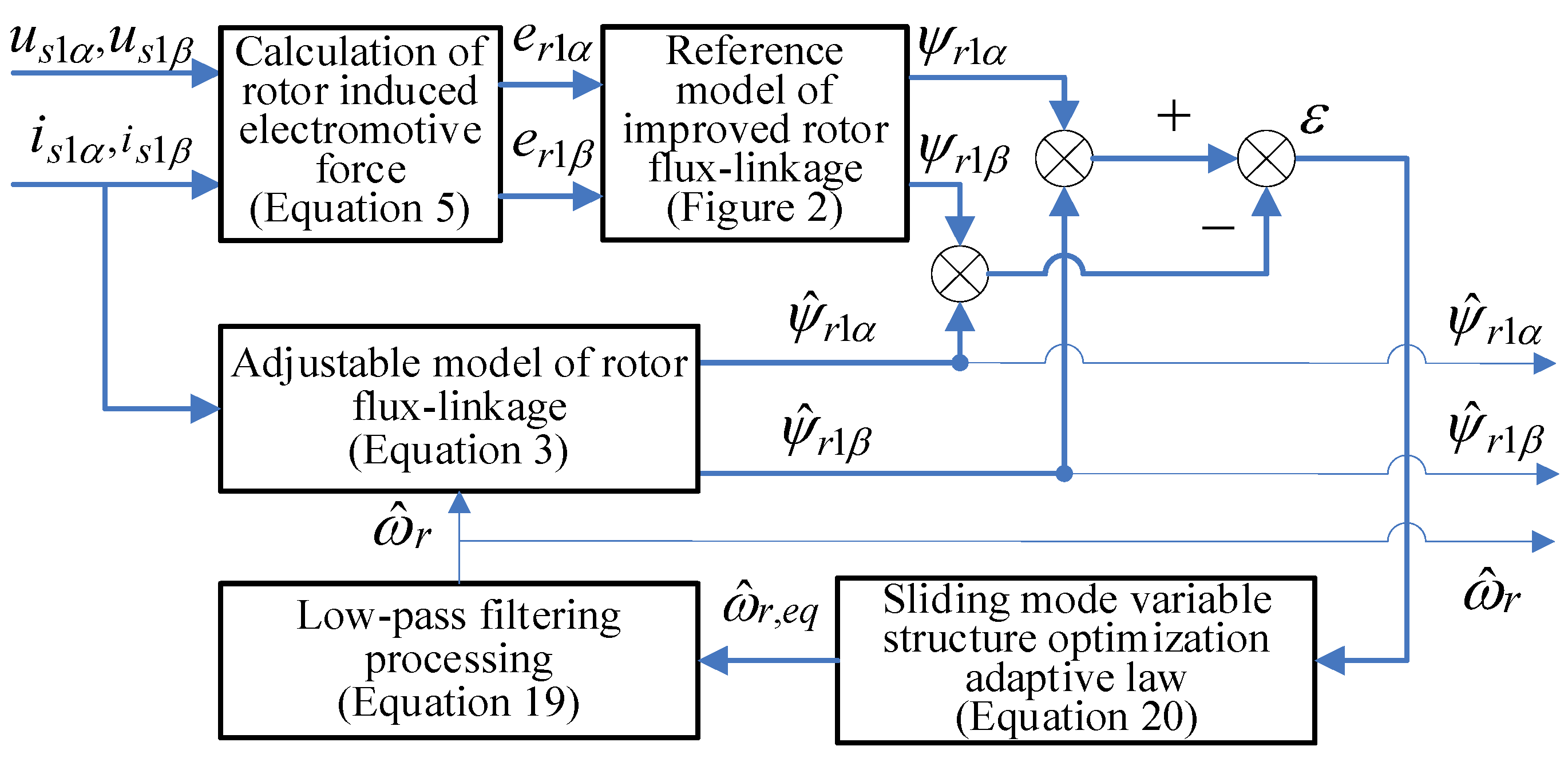
Figure 3 is the schematic structure of the VS-MRAS speed identifier. In Figure 3, according to Equation (5), the inputted voltage components, us1α and us1β, and current components, is1α and is1β, should be first transformed to the rotor-induced electromotive force components, i.e., er1α and er1β. After inputting er1α and er1β into the improved integrator in Figure 2, the relevant rotor flux-linkage components ψr1α and ψr1β are obtained. Then, combining the output of the adjustable model of rotor flux-linkage and the improved sliding mode variable structure adaptive law, the rotor flux-linkage observation and speed identification can be achieved.

3. Speed Sensorless Inverse Decoupling Control System of a BL-IM

In the orthogonal coordinate system of synchronous rotation, the mathematical models for the radial suspension force of a BL-IM are as follows [9]:
F α = K m ( i s 2 d ψ 1 d + i s 2 q ψ 1 q ) F β = K m ( i s 2 d ψ 1 q i s 2 q ψ 1 d ) K m = π L m 2 / ( 4 μ 0 l r N 1 N 2 )
where Km is the magnetic levitation force coefficient; Fα and Fβ are the controllable magnetic levitation force components in horizontal and vertical directions; is2d and is2q are the d-axis and q-axis components of suspension current, respectively; ψ 1 d and ψ 1 q are the d-axis and q-axis air gap flux-linkage components of torque system; μ0 is air gap permeability; l is the stator core length; r is the inner radius of stator; Lm2 is the single phase excitation inductance of suspension winding; N1 and N2 are the effective number of series turns for torque winding and suspension winding, respectively.
According to the principles of mechanical dynamics, the radial suspension motion equation of the rotor can be expressed as follows:
m α ¨ = F α + f α ,   m β ¨ = F β + f β
where m is the rotor mass; fα and fβ are the unbalanced magnetic pull force components along the horizontal and vertical directions; their expressions are as follows:
f α = k s α , f β = k s β
where ks is the radial displacement stiffness coefficient, and its calculation formula is as follows:
k s = π r l B 2 / ( 2 μ 0 δ 0 )
where δ0 is the average air gap length, and B is the air gap flux density amplitude of the four-pole torque system.
Based on the relationship between air gap flux-linkage and rotor flux-linkage, the air gap flux-linkage components of the torque system are obtained as follows:
ψ 1 d = L m 1 ( ψ r 1 + L r 1 l i s 1 d ) / L r 1 ψ 1 q = L m 1 L r l i s 1 q L r 1
where ψr1 is the rotor flux-linkage of the torque system, and Lr1l is the rotor leakage inductance.
The state variable X and input variable U of the system are selected as follows:
X = [ x 1 , x 2 , x 3 , x 4 , x 5 , x 6 , x 7 , x 8 ] T = [ α , β , α ˙ , β ˙ , i s 1 d , i s 1 q , ψ r 1 , ω r ] T
U = [ u 1 , u 2 , u 3 , u 4 ] T = [ u s 1 d , u s 1 q , i s 2 d , i s 2 q ] T
The output variable Y is selected as follows:
Y = [ y 1 , y 2 , y 3 , y 4 ] T = [ α , β , ψ r 1 , ω r ] T
The input variable of the inverse system is selected as follows:
ν = [ ν 1 , ν 2 , ν 3 , ν 4 ] T = [ y ¨ 1 , y ¨ 2 , y ¨ 3 , y ¨ 4 ] T
Based on Equations (22)–(30) and according to the inverse system theory, the inverse system decoupling model of a BL-IM system can be obtained as follows [9]:
u 1 = 1 ξ [ 1 δ L m 1 v 3 + γ x 5 δ ( ξ η + 1 L m 1 ) x 7 ( x 8 + L m 1 δ x 6 x 7 ) x 6 ] u 2 = 1 ξ [ 1 μ x 7 v 4 + γ x 6 + x 5 x 8 + ξ η x 7 x 8 ] u 3 = L r 1 L m 1 K m [ ( x 7 + L r 1 l x 5 ) 2 + ( L r 1 l x 6 ) 2 ] × [ L r 1 l x 6 ( m ν 2 + f β ) + ( x 7 + L r 1 l x 5 ) ( m ν 1 + f α ) ] u 4 = L r 1 L m 1 K m [ ( x 7 + L r 1 l x 5 ) 2 + ( L r 1 l x 6 ) 2 ] × [ L r 1 l x 6 ( m ν 1 + f α ) ( x 7 + L r 1 l x 5 ) ( m ν 2 + f β ) ]
where γ = R s 1 / σ L s 1 + R r 1 / σ L r 1 , σ = 1 L m 1 2 / L s 1 L r 1 , δ = R r 1 / L r 1 , ξ = 1 / σ L s 1 , μ = p 1 2 L m 1 / J L r 1 , η = L m 1 / L r 1 .
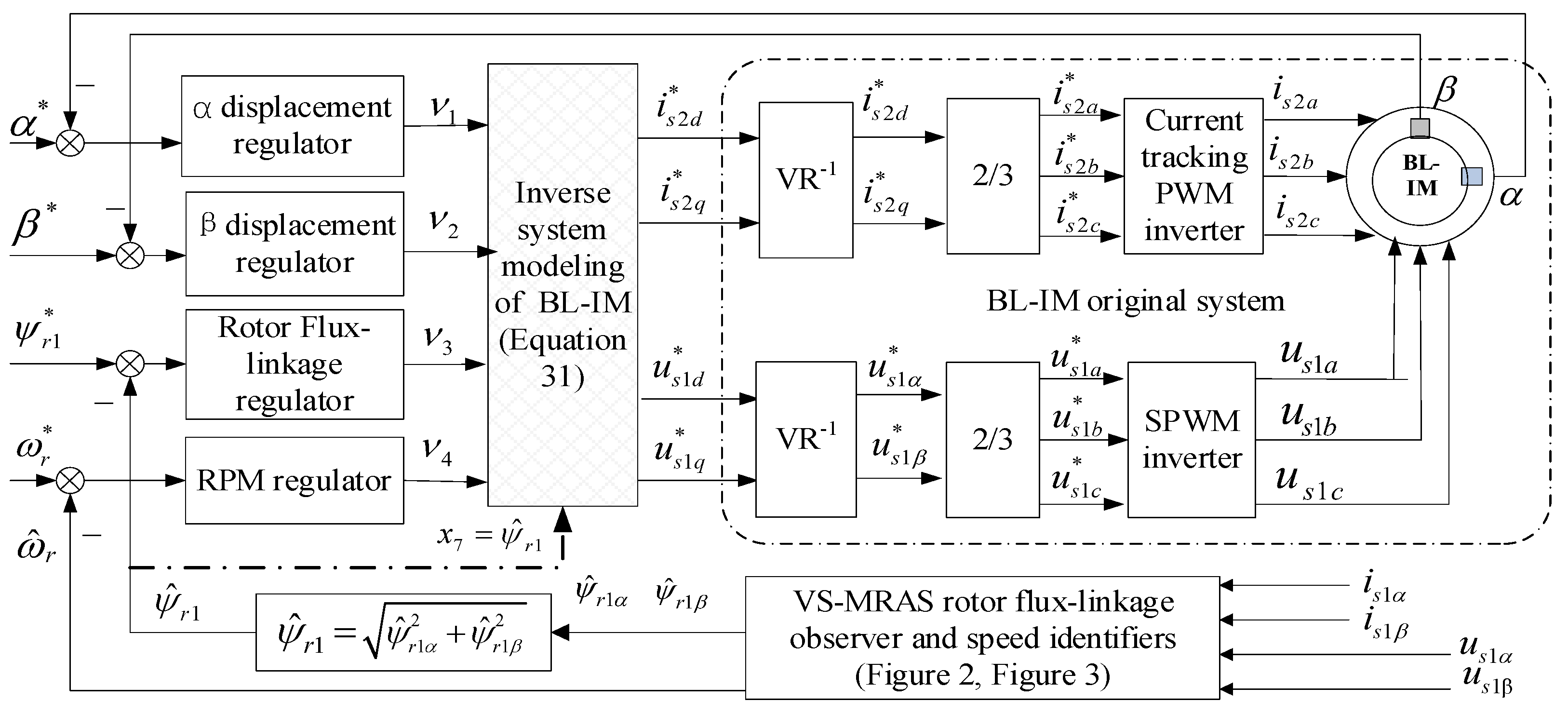
Figure 4 gives the principle structure of the speed sensorless inverse decoupling control system of a BL-IM. Firstly, by series connecting the inverse system model before the original BL-IM system and using the observed rotor flux-linkage ψ ^ r 1 to real-time update the state variable x7 in the inverse system model in Equation (31), the overall BL-IM system is decoupled into four second-order pseudo linear subsystems. Then, the speed and observed rotor flux-linkage are identified, and the measured α- and β-radial displacement components are used as feedback signals; after they are comprehensively compared with the given values of corresponding variables through the closed-loop adjustment of each subsystem, the decoupling control of each subsystem can be achieved, ultimately achieving the goal of speed sensorless vector control for a BL-IM. The four subsystems can achieve good control effects by using a PD regulator with an inertial filtering link.

4. Speed Sensorless Control System Simulation Verification and Analysis

To verify the effectiveness of the proposed speed identification method, according to the system structure shown in Figure 4, the simulation experiment was conducted using MATLAB/Simulink R2019a. The simulated BL-IM parameters are as shown in Table 1.
The set simulation conditions are as follows: given speed ωr* = 1500 r/min; given rotor flux-linkage ψr1* = 0.6 Wb; given radial displacement components α* = β* = 0; initial radial displacement α0 = −0.12 mm and β0 = −0.16 mm; torque load TL = 0. After simulation and debugging, when selecting a low-pass filter with T ≤ 0.1, a good speed identification response waveform can be obtained. In this paper, T is set to 0.001.
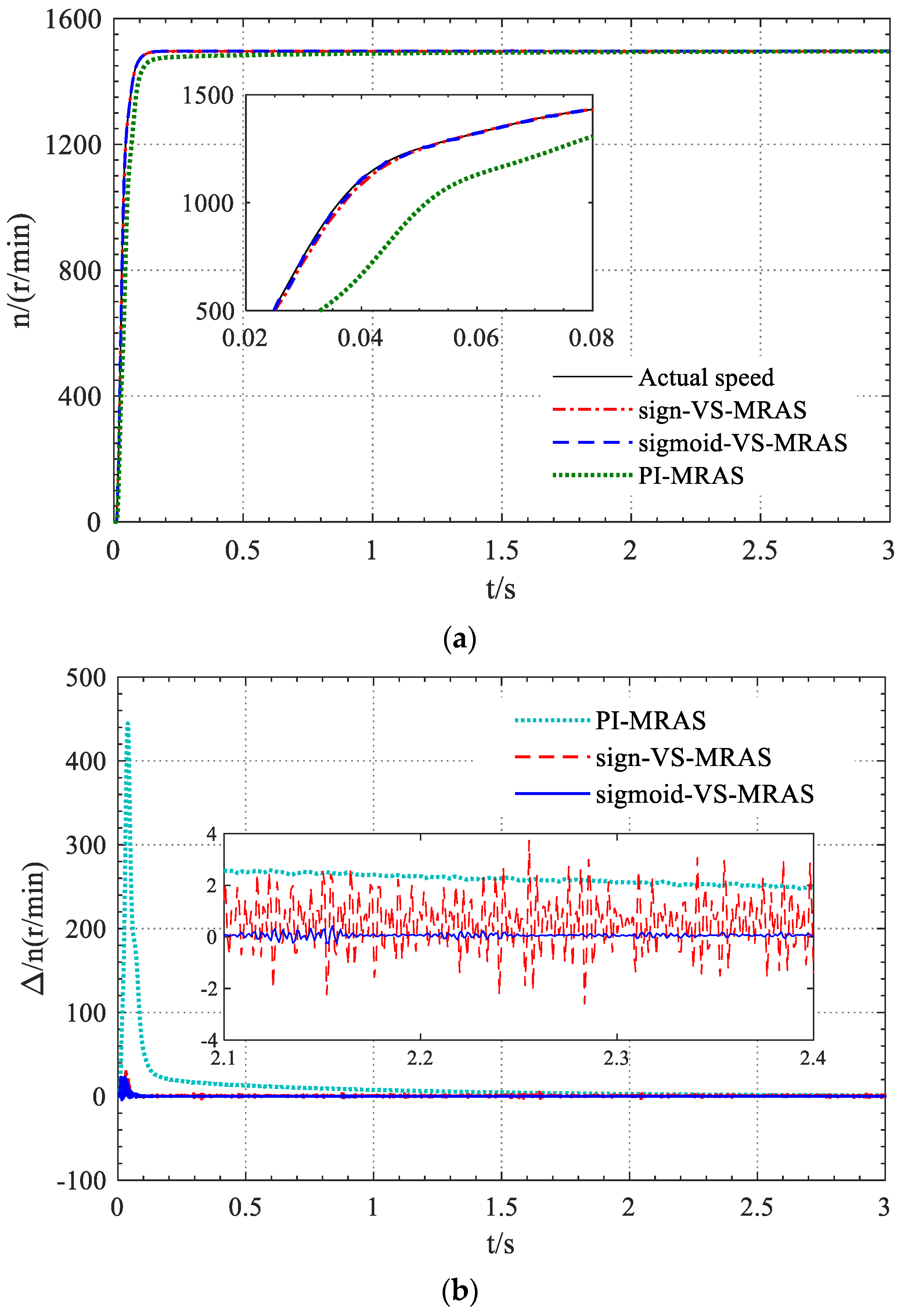
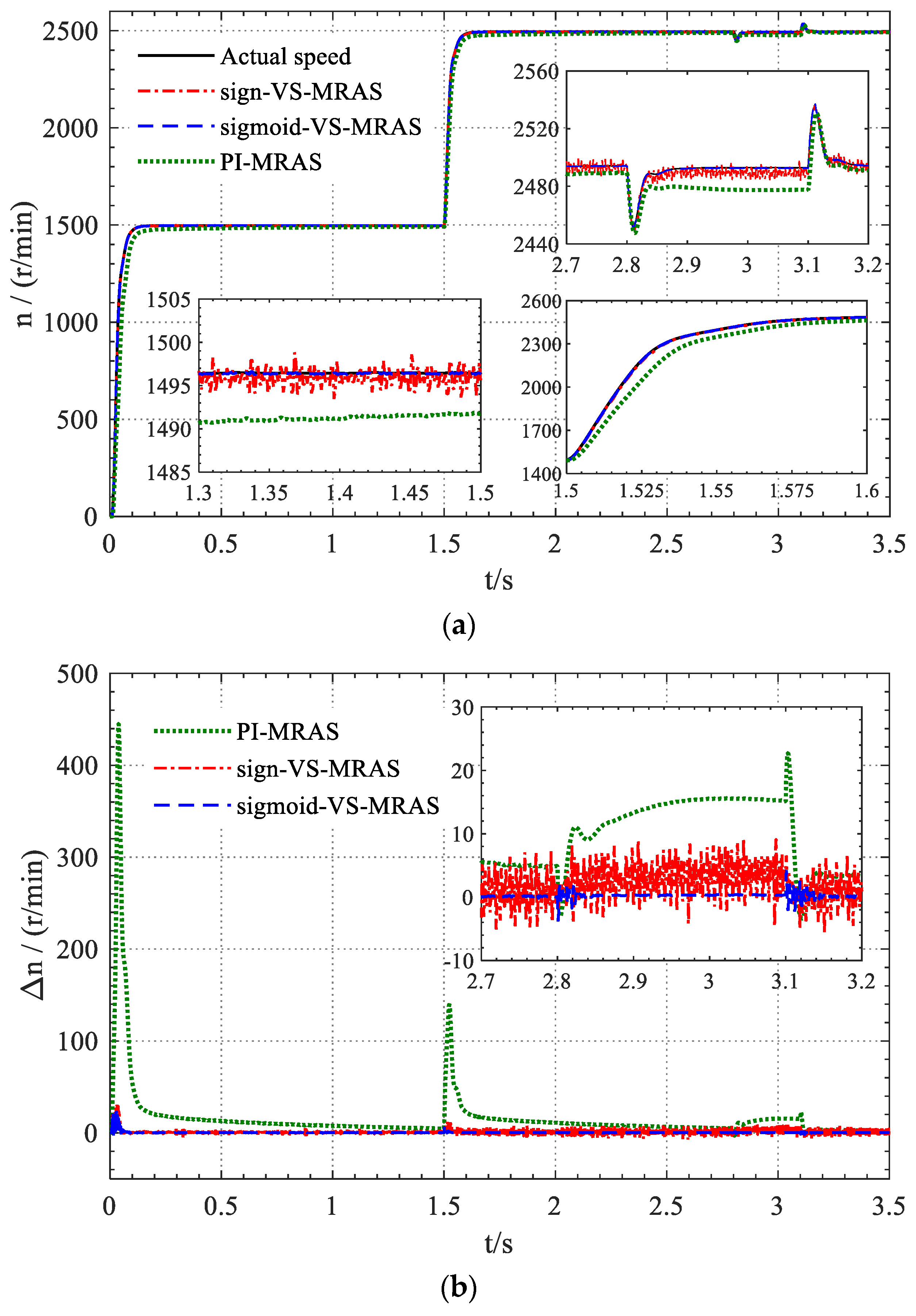
To verify the effectiveness and superiority of the proposed VS-MRAS speed identification method based on sigmoid function sliding mode variable structure adaptive law (referred to as “sigmoid-VS-MRAS”), the system simulation response waveforms of the VS-MRAS speed identification method using sign function sliding mode variable structure adaptive law (referred to as “sign-VS-MRAS”), and those of the MRAS method that uses PI adaptive law without improving the flux-linkage model (referred to as “PI-MRAS”) were provided simultaneously, and the comparison of relevant simulation experiment results was conducted. Figure 5 shows the speed response waveform during no-load starting. From Figure 5, the research results are as follows:
(1)
Compared with the traditional PI-MRAS speed identification method, the “sigmoid-VS-MRAS” speed identification method can achieve timely tracking of speed during motor starting, and the steady-state error is small. Mainly due to the influence of the pure integration link on the reference model of the traditional PI-MRAS method, the reliability of the reference model is reduced, especially at low speeds. The “sigmoid-VS-MRAS” method has improved the reference model, improved its reliability, and adopted a sliding mode variable structure optimization adaptive law to improve the response speed and robustness of speed identification; therefore, the tracking accuracy and rapidity of motor speed have been greatly improved, and the steady-state error is smaller.
(2)
Because the sliding mode variable structure adaptive law improves the response rapidity of MRAS speed identification, both “sigmoid-VS-MRAS” and “sign VS-MRAS” methods can achieve faster speed tracking effects. However, when using “sign-VS-MRAS”, there are high-frequency harmonics or oscillations with an amplitude of about 3.0 r/min in the identified motor speed. The reason for this is the rapid switching and switching time delay of discontinuous switching functions. When using the “sigmoid-VS-MRAS” speed identification method proposed in this paper, the chattering phenomenon is significantly suppressed, and the high-frequency harmonics in the identified speed are greatly suppressed. Except for a small amount of identification error at the startup moment, high identification accuracy and high tracking rapidity can be achieved during the startup process and steady-state operation.
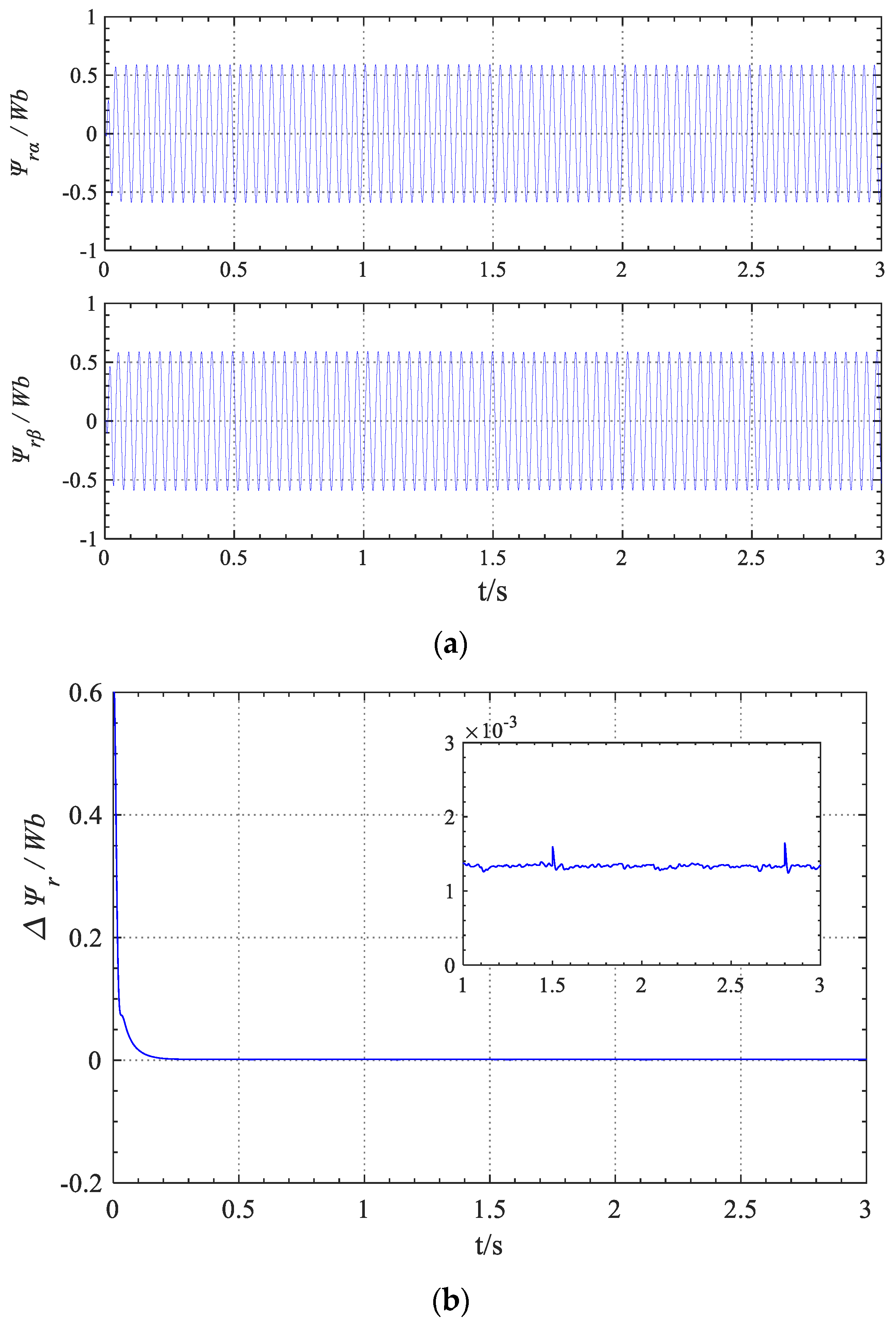
Under no-load conditions, Figure 6 shows the rotor flux-linkage observation response waveform after improving the voltage model, as well as the error waveform between the observed rotor flux-linkage amplitude and the given value of rotor flux-linkage. From Figure 6, it can be seen that the improved rotor flux-linkage voltage model has eliminated the influence of the pure integrator; except for the dynamic adjustment stage at the moment of motor starting, the observation error of rotor flux-linkage is always within 0.0015 Wb. Therefore, high rotor flux-linkage observation accuracy is achieved, which provides a reliable calculation basis for the stable suspension control of a BL-IM system.
In order to verify the speed identification performance of the proposed “sigmoid-VS-MRAS” method under load and adjusting speed conditions, as well as the dynamic decoupling performance between various variables, it is set that each controlled variable undergoes sudden changes at different times. At 1.5 s, increasing the given speed ωr* to 2500 r/min, a load of 8.4 N.m is suddenly applied at 2.8 s and suddenly unloaded at 3.1 s, the given α* is mutated to −0.06 mm at 2 s and recovered to 0 mm at 2.3 s, and the given β* is mutated to 0.06 mm at 2.4 s and returned to 0 mm at 2.7 s. Figure 7 and Figure 8 show the response waveforms of the BL-IM system. Among them, Figure 7 shows the motor speed response waveform during load operation and speed regulation.
(1)
During on-load operation and speed regulation processes, the “sigmoid-VS-MRAS” speed identification method can still achieve higher identification and tracking performance than the PI MRAS method. Compared to the “sign-VS-MRAS” method, it still overcomes the chattering problem; moreover, the identified speed basically does not contain higher harmonics, and it still has a higher speed identification accuracy.
(2)
Under the same load sudden change conditions, when using the traditional PI-MRAS method, there was a speed drop deviation of about 20 r/min, and the speed recovery process was relatively slow. When using the “sign-VS-MRAS” method, due to the fast nature of sliding mode variable structure control, only a small speed fluctuation of about 5 r/min was generated. When using the proposed “sigmoid-VS-MRAS” method, not only can the motor speed recover to its original stable state within 0.05 s, but also, due to the high identification accuracy of the “sigmoid-VS-MRAS” method, the BL-IM system can still achieve higher speed control accuracy than that case when using the “sign-VS-MRAS” method. After loading, the steady-state speed of the BL-IM system can still be maintained at zero deviation.
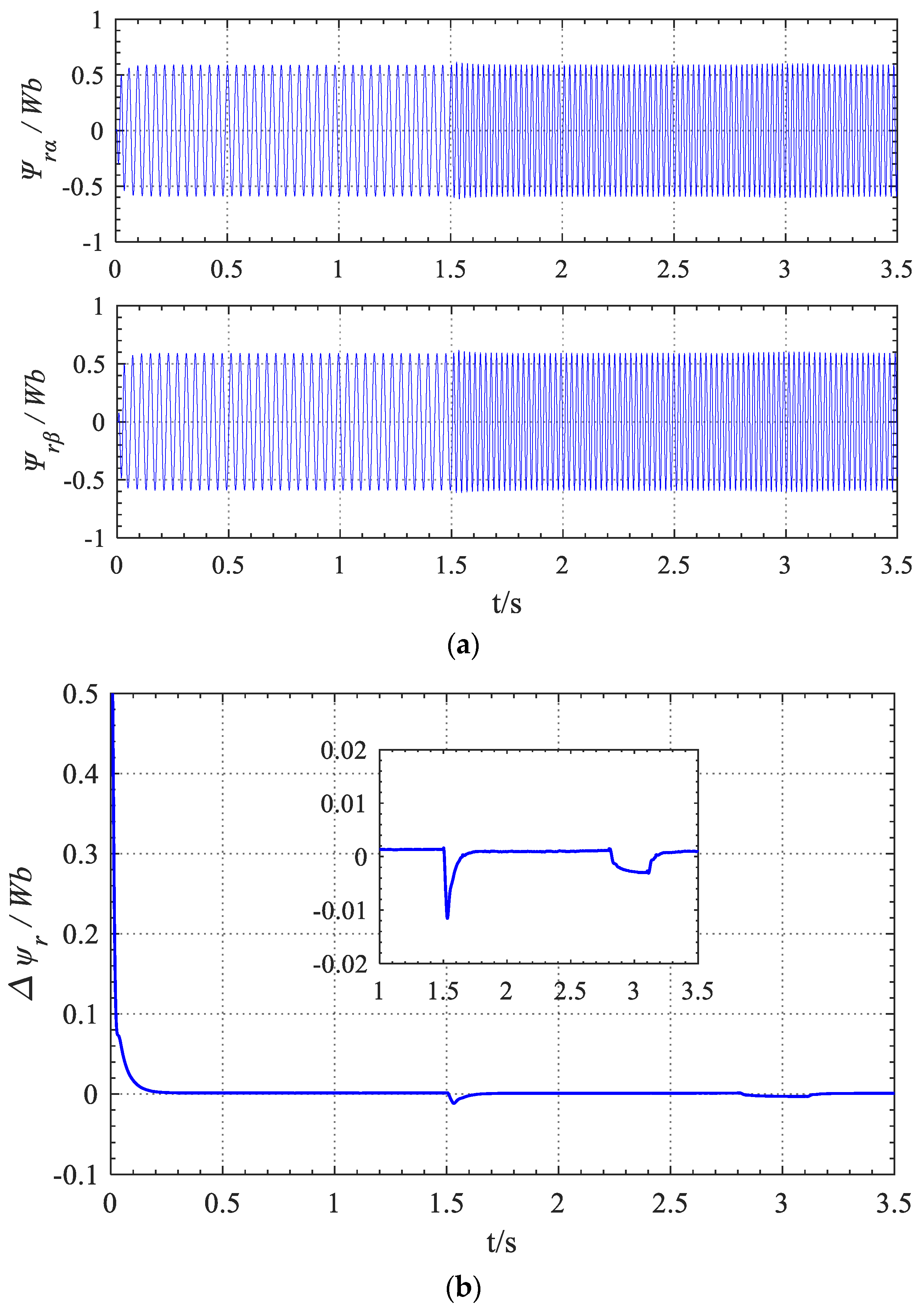
During the on-load operation and speed regulation processes, Figure 8 shows the response waveform of the observed rotor flux-linkage after improving the voltage model, as well as the error waveform between the given value and the observed value of the rotor flux-linkage amplitude. From Figure 8, it can be seen that during speed regulation and load mutation, although the identification error of the rotor flux-linkage slightly increases compared to no-load conditions, the observation error remains within 0.01 Wb, still maintaining a relatively high observation effect of the rotor flux-linkage.
Figure 9 shows the response waveform of the radial displacement of the bearingless rotor. Overall, considering the simulation experimental results in Figure 7, Figure 8 and Figure 9, the research results are as follows:
(1)
After using the “sigmoid-VS-MRAS” speed identifier proposed in this paper, the radial displacement component of the rotor is basically not affected by the sudden changes in load and speed. At the same time, when the radial displacement of the rotor suddenly changes, it has an instantaneous slight overshoot of about 0.02 mm, and the motor speed and the rotor flux-linkage are also basically unaffected.
(2)
Based on the inverse dynamic decoupling control system of BL-IM [10], after replacing the mechanical speed sensor with the proposed “sigmoid-VS-MRAS” speed identifier, stable maglev operation control can still be achieved; moreover, the speed sensorless control system can still achieve good dynamic and static decoupling control performance.

5. Conclusions

To achieve the high-performance speed sensorless control of BL-IM, this paper, adopting a sigmoid function, investigates a sliding mode variable structure MRAS speed identification method, i.e., the “sigmoid-VS-MRAS” identification method. Firstly, the reference voltage model of rotor flux-linkage in the traditional MRAS speed identifier is improved through an equivalent integration link. Then, a sliding mode variable structure adaptive law is used to replace the PI adaptive law in the MRAS speed identifier, and a smooth continuous sigmoid(.) function is used to replace the symbol function to improve the sliding mode variable structure adaptive rate. Finally, based on the inverse dynamic decoupling control system of a BL-IM, the speed sensorless vector control system simulation experiment was conducted. The specific research conclusions are as follows:
(1)
After improving the rotor flux-linkage reference model with an equivalent integration link, the influence of the initial value and cumulative error of the integrator can be effectively eliminated, and higher rotor flux-linkage observation accuracy can be achieved. On this basis, it can effectively improve the reliability and accuracy of speed identification.
(2)
Because it inherits the fast control characteristics of sliding mode control, when using the sliding mode variable structure adaptive law to replace the traditional PI adaptive law, the rapidity of speed identification and tracking can be effectively improved, and stronger resistance to load disturbances can be obtained.
(3)
After replacing the symbol function with the sigmoid function that has smooth and continuous characteristics, the sliding mode variable structure adaptive rate can be significantly improved, and the high-order harmonic problem caused by sliding mode chattering in the identification speed waveform can be effectively reduced, thus effectively improving the speed identification accuracy and obtaining better steady-state and dynamic speed identification and tracking performance.
(4)
After updating the relevant variables in the inverse system model with the observed rotor flux-linkage in real time and replacing the mechanical speed sensor with the proposed sigmoid-VS-MRAS speed identifier, not only the stable operation control of the inverse decoupling control system of BL-IM can be achieved, but good steady-state and dynamic decoupling control performance between speed system and suspension system can also still be obtained.
Discussion: Although the sigmoid-VS-MRAS speed identification method can achieve high identification accuracy in both steady-state and dynamic processes, there is still a small rotor flux-linkage observation error within 0.01 Wb during variable speed and load sudden changes, which, to some extent, affects the improvement of speed dynamic identification accuracy. How to further improve the observation accuracy of rotor flux-linkage and the dynamic identification accuracy of speed is a problem that requires additional research.

Author Contributions

Investigation & methodology, Y.C.; Writing—review & editing, W.T.; Conceptualization & Supervision, W.B. All authors have read and agreed to the published version of the manuscript.

Funding

The support of the National Natural Science Foundation of China (51277053) and the Key scientific and technological project in Henan province (202102210095) are acknowledged.

Data Availability Statement

The data presented in this study are available on request from the corresponding author.

Conflicts of Interest

The authors declare no conflicts of interest.

References

  1. Nielsen, K.K.; Bahl, C.R.H.; Dagnaes, N.A.; Santos, I.F.; Bjork, R. A Passive Permanent Magnetic Bearing with Increased Axial Lift Relative to Radial Stiffness. IEEE Trans. Magn. 2021, 57, 8300108. [Google Scholar] [CrossRef]
  2. Pei, T.; Li, D.; Liu, J.; Li, J.; Kong, W. Review of Bearingless Synchronous Motors: Principle and Topology. IEEE Trans. Transp. Electrif. 2022, 8, 3489–3502. [Google Scholar] [CrossRef]
  3. Chen, J.; Zhu, J.; Severson, E.L. Review of Bearingless Motor Technology for Significant Power Applications. IEEE Trans. Ind. Appl. 2020, 56, 1377–1388. [Google Scholar] [CrossRef]
  4. Sun, X.; Jin, Z.; Cai, Y.; Yang, Z.; Chen, L. Grey Wolf Optimization Algorithm Based State Feedback Control for a Bearingless Permanent Magnet Synchronous Machine. IEEE Trans. Power Electron. 2020, 35, 13631–13640. [Google Scholar] [CrossRef]
  5. Bao, X.; Wang, X.; Ding, Q.; Shi, T. Design of Double Staggered Parallel Bearingless Motor Drive System. IEEE Trans. Power Electron. 2023, 38, 2230–2239. [Google Scholar] [CrossRef]
  6. Wang, Z.; Cao, X.; Deng, Z.; Cai, J.; Deng, X. High Integrated Methodology and Evaluation for Switched-Reluctance Type Bearingless Motors with Five Degree of Freedom Magnetic Levitation. IEEE Trans. Energy Convers. 2023, 38, 759–770. [Google Scholar] [CrossRef]
  7. Chen, Y.; Bu, W.; Qiao, Y. Research on the Speed Sliding Mode Observation Method of a Bearingless Induction Motor. Energies 2021, 14, 864. [Google Scholar] [CrossRef]
  8. Cao, J.; Sun, X.; Tian, X. Optimal control strategy of state feedback control for surface-mounted PMSM drives based on auto-tuning of seeker optimization algorithm. Int. J. Appl. Electromagn. Mech. 2021, 66, 705–725. [Google Scholar] [CrossRef]
  9. Bu, W.; Li, B.; He, F.; Li, J. Inverse system decoupling sliding mode control Strategy of Bearingless Induction Motor Considering Current Dynamics. Int. J. Appl. Electromagn. Mech. 2019, 60, 63–78. [Google Scholar] [CrossRef]
  10. Yang, Z.; Wang, D.; Sun, X.; Wu, J. Speed sensorless control of a bearingless induction motor with combined neural network and fractional sliding mode. Mechatronics 2022, 82, 102721. [Google Scholar] [CrossRef]
  11. Sun, C.; Yang, Z.; Sun, X.; Ding, Q. An Improved Mathematical Model for Speed Sensorless Control of Fixed Pole Bearingless Induction Motor. IEEE Trans. Ind. Electron. 2024, 71, 1286–1295. [Google Scholar] [CrossRef]
  12. Bu, W.S.; Zu, C.L.; Wang, S.J. MRAS Speed Identification of Bearingless Induction Motor Based on Rotor Flux Orientation. Control. Eng. China 2014, 21, 334–337, 342. [Google Scholar]
  13. Rao, P.N.; Kumar, N.M.; Padmanaban, S.; Subathra, M.S.P.; Chand, A.A. A Novel Sensorless Approach for Speed and Displacement Control of Bearingless Switched Reluctance Motor. Appl. Sci. 2020, 10, 4070. [Google Scholar] [CrossRef]
  14. Zhao, Q.; Yang, Z.; Sun, X.; Ding, Q. Speed-sensorless control system of a bearingless induction motor based on iterative central difference Kalman filter. Int. J. Electron. 2020, 107, 1524–1542. [Google Scholar] [CrossRef]
  15. Bian, Y.; Yang, Z.; Sun, X.; Wang, X. Speed Sensorless Control of a Bearingless Induction Motor Based on Modified Robust Kalman Filter. J. Electr. Eng. Technol. 2024, 19, 1179–1190. [Google Scholar] [CrossRef]
  16. Wang, G.; Yang, L.; Zhang, G.; Zhang, X.; Xu, D. Comparative Investigation of Pseudorandom High-Frequency Signal Injection Schemes for Sensorless IPMSM Drives. IEEE Trans. Power Electron. 2017, 32, 2123–2132. [Google Scholar] [CrossRef]
  17. Xu, T.; Yang, Z.; Sun, X.; Jia, J. Speed sensorless control of a bearingless induction motor based on fuzzy PI fractional MRAS scheme. Int. J. Green Energy 2022, 19, 389–398. [Google Scholar] [CrossRef]
  18. Sun, Y.Q.; Yang, Z.B.; Sun, X.D.; Sun, C. Speed sensorless control of a BL-IM based on an adaptive nonsingular terminal sliding mode observer. Int. J. Electron. 2023, 110, 341–359. [Google Scholar] [CrossRef]
  19. Yang, Z.; Ding, Q.; Sun, X.; Lu, C.; Zhu, H. Speed sensorless control of a bearingless induction motor based on sliding mode observer and phase-locked loop. ISA Trans. 2022, 123, 346–356. [Google Scholar] [CrossRef] [PubMed]
  20. Holakooie, M.H.; Ojaghi, M.; Taheri, A. Modified DTC of a Six-Phase Induction Motor with a Second-Order Sliding-Mode MRAS-Based Speed Estimator. IEEE Trans. Power Electron. 2019, 34, 600–611. [Google Scholar] [CrossRef]
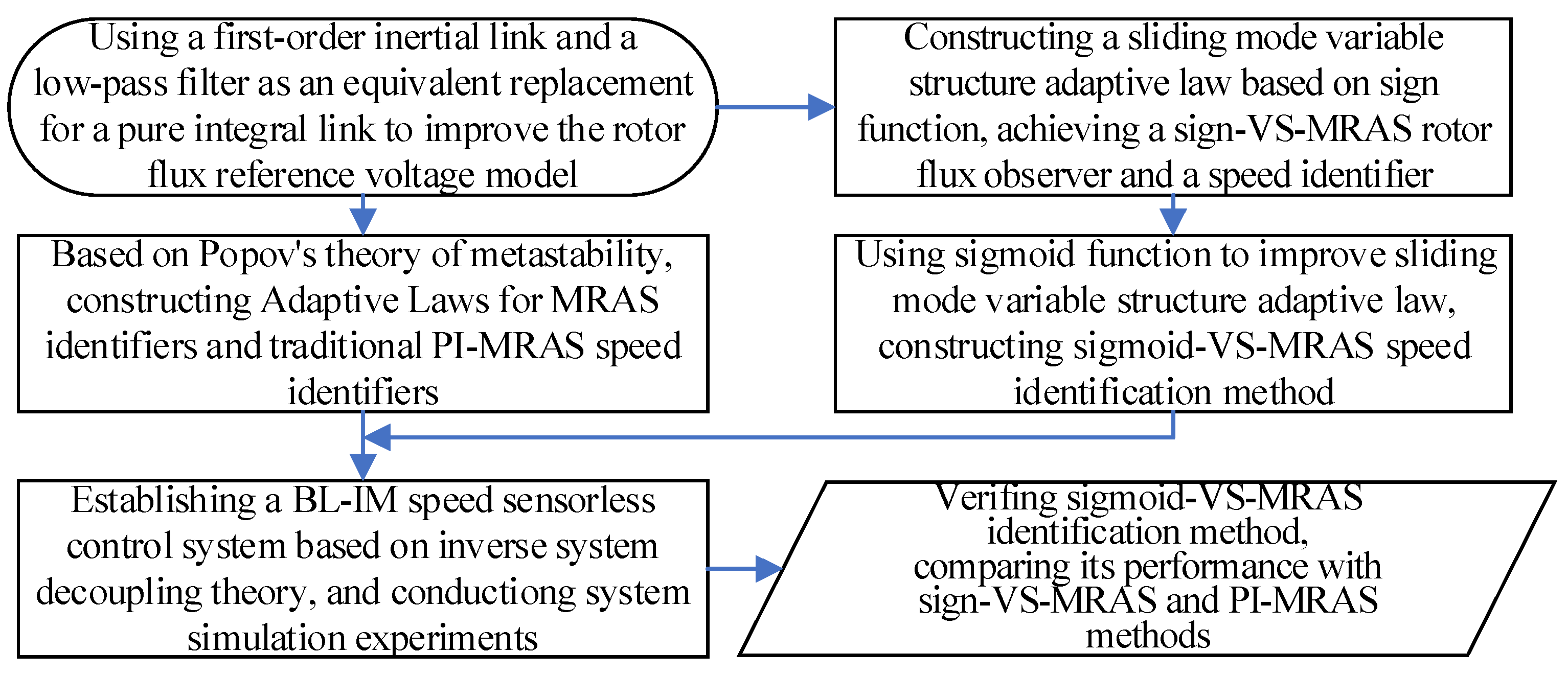
Figure 1. Schematic diagram of research method flow.
Energies 17 02615 g001
Figure 2. Schematic diagram of improved rotor flux-linkage voltage model.
Energies 17 02615 g002
Figure 3. Structure diagram of VS-MRAS rotor flux-linkage observation and speed identification.
Energies 17 02615 g003
Figure 4. Speed sensorless inverse decoupling control system structure of a BL-IM based on VS-MRAS speed identification.
Energies 17 02615 g004
Figure 5. Motor speed response waveform on non-load starting: (a) speed response waveform; (b) identification error of motor speed.
Energies 17 02615 g005
Figure 6. Rotor flux-linkage waveform at no load: (a) α-axis and β-axis rotor flux-linkage components; (b) error between the amplitude and given value of rotor flux-linkage.
Energies 17 02615 g006
Figure 7. Seed response waveform during loading and speed regulation: (a) response waveform of motor speed; (b) identification error of motor speed.
Energies 17 02615 g007
Figure 8. Response waveforms of rotor flux-linkage during loading and speed regulation: (a) waveforms of α-axis and β-axis rotor flux-linkage components; (b) error waveform between the amplitude of the rotor flux-linkage and its given value.
Energies 17 02615 g008
Figure 9. Response waveforms of α-axis and β-axis displacements.
Energies 17 02615 g009
Table 1. Parameters of a BL-IM.
ParameterTorque SystemLevitation System
Stator resistance1.6 Ω2.7 Ω
Stator leakage-inductance0.0043 H0.00398 H
Rotor resistance1.423 Ω2.344 Ω
Rotor leakage-inductance0.0043 H0.00398 H
Single-phase excitation inductance0.0859 H0.230 H
Power2.2 kW-
Inner radius of stator62 mm
Length of rotor core82 mm
Average air gap of motor0.6 mm
Clearance of auxiliary bearings0.2 mm
Rotor inertia0.024 kg·m2
Disclaimer/Publisher’s Note: The statements, opinions and data contained in all publications are solely those of the individual author(s) and contributor(s) and not of MDPI and/or the editor(s). MDPI and/or the editor(s) disclaim responsibility for any injury to people or property resulting from any ideas, methods, instructions or products referred to in the content.