Article

Performance Analysis and Optimization of Compressed Air Energy Storage Integrated with Latent Thermal Energy Storage

1
College of Energy Engineering, Zhejiang University, Hangzhou 310027, China
2
School of Chemical Engineering, University of Birmingham, Edgbaston, Birmingham B15 2TT, UK
*
Author to whom correspondence should be addressed.
Energies 2024, 17(11), 2608; https://doi.org/10.3390/en17112608
Submission received: 22 April 2024 / Revised: 24 May 2024 / Accepted: 27 May 2024 / Published: 28 May 2024

Abstract

:
Recovering compression waste heat using latent thermal energy storage (LTES) is a promising method to enhance the round-trip efficiency of compressed air energy storage (CAES) systems. In this study, a systematic thermodynamic model coupled with a concentric diffusion heat transfer model of the cylindrical packed-bed LTES is established for a CAES system, and the numerical simulation model is validated by experimental data in the reference. Based on the numerical model, the charging–discharging performance of LTES and CAES systems is evaluated under different layouts of phase change materials (PCMs) in LTES, and the optimal layout of PCM is specified as a three-stage layout, since the exergy efficiency of LTES and round-trip efficiency are improved by 8.2% and 6.9% compared with a one-stage layout. Then, the proportion of three PCMs is optimized using response surface methods. The optimization results indicate that the exergy efficiency of LTES and round-trip efficiency of the CAES system are expected to be 80.9% and 73.3% under the PCM proportion of 0.48:0.3:0.22 for three stages, which are 7.0% and 13.1% higher than the original three-stage PCMs with equal proportions.

1. Introduction

Renewable energy utilization has been a world-wide critical issue due to the increasingly serious energy crises and environmental pollution [1,2], and solar energy and wind energy are playing a dominating role among all of the renewable energies [3]. However, the fluctuating and intermittent nature of renewable energies threatens the reliability and overall efficiency of electrical power systems [4]. Promising methods are the applications of various energy storage techniques, including electric vehicles and electro-chemical energy storage [5], pumped hydro energy storage [6,7], thermal energy storage [8,9], compressed air energy storage [10,11], etc. Among all of the large-scale energy storage technologies, the compressed air energy storage (CAES) possesses unique advantages since it is not restricted by geographical conditions and has a long lifespan, high reliability, and low cost [12,13], and it has been attracting increasing attention around the world.
The fundamental of the CAES system is that air is compressed to a high-pressure state and stored in underground space or tanks using surplus renewable energy electricity, and the stored high-pressure air then is used to drive the turbine for electricity in peak-load hours [14,15]. As an efficient and reliable energy storage technology to balance the electricity supply and demand, the investigations and applications of CAESs can be traced back to the 1960s. With the improvement in the penetration of renewable energy in grids, new energy grids integrating with CAESs have been widely investigated and surprising advances have been made [16]. In the 20th century, only two commercial CAES power plants were put into service, namely the Huntorf station in Germany [17] and the McIntosh station in America [18]. In these two conventional CAES systems, fossil fuels are burned to heat the high-pressure air for higher expansion efficiency during the discharging process, and this technical routine is not within the consideration of policy-makers due to the urgent concern of reducing CO2 emissions around the world. Recently, the advanced compressed air energy storage (A-CAES) system has been proposed, which considers the utilization of the compression heat of compressors during the charging process [19]. In an A-CAES system, thermal energy storage (TES) materials are used to store the compression heat of compressed air during the compression process and release heat to high-pressure air during the expansion process, and a key issue is to design proper thermal energy storage heat exchangers and match proper energy storage materials.
Cylindrical packed-bed thermal energy storage is the most considered in previous studies due to the significantly larger heat transfer area compared with the shell-and-tube heat exchangers [20], providing a larger heat transfer rate between the air and energy storage materials considering their low thermal conductivity [21]. Edward et al. [22] investigated the influence of the structure of packed bed, the dynamic charging–discharging characteristics of packed-bed thermal energy storage, and the number of cycles on the performance of an A-CAES system. The results showed that the round-trip efficiency of the system using packed-bed heat storage could reach over 70%, significantly higher than that of the A-CAES system using dual-tank thermal energy storage using water. Presently, thermal energy storage materials such as water and bricks are considered to be sensible due to their large heat capacity and low cost. Zhao et al. [23] analyzed the dynamic performance of an A-CAES system integrated with two-stage sensible thermal energy storage, and the results specified the importance of matching working temperature between the energy storage materials and air. Although sensible thermal energy storage can enhance the round-trip efficiency of the CAES system, the low thermal energy storage density of materials can lead to the high working temperature of pack-bed heat exchangers, and this will further result in a thermocline exergy with large temperature gradient. That is, more rigorous requirements on the reliability of packed-bed thermal energy storage need to be satisfied [24].
To tackle this issue, CAESs integrated with packed-bed latent thermal energy storage are a more promising solution because of the large thermal energy storage density and relatively low working temperature during the melting and solidification process [25]. The thermodynamic performance of a CAES system with cascaded PCMs in packed-bed latent thermal energy storage was investigated by Tessier et al. [26] without considering the heat transfer process inside the PCM. The simulation results indicated that the cascaded PCM layout reduced the exergy loss of the heat transfer process between the air and PCMs. In addition, the melting temperature, latent heat, and stages of PCMs were demonstrated as important parameters for system performance. To improve the matching working temperature between the air and PCMs in the LTES, Shadi et al. [27] analyzed the dynamic performance of a CAES system where PCMs were arranged in three stages based on the order of melting temperature. The results demonstrated the superiority of the cascaded PCM layouts to improve the recovery rate of the compression heat and temperature uniformity of packed-bed LTES. However, the design and optimization of the melting temperature of PCMs and proportion of each stage are not considered. Li et al. [28] studied the effects of different PCM layouts in LTES on the performance of the CAES system. The results showed that PCMs arranged in two stages contributed to significantly lower exergy loss in the LTES compared with that of only one PCM used in LTES, and they also specified the critical role of the PCM proportion of each stage in determining the charging and discharging performance of the CAES system. Yu et al. [29], in our research group, revealed the effects of PCM thermophysical properties on the performance of packed-bed LTES and CAES systems based on orthogonal experiments and the TOPSIS method, and proposed a PCM selection method for CAES systems. Gong et al. [30] analyzed the heat transfer performance of the LTES system integrated with single, two, three, and five PCMs, which were compared and optimized from the perspective of exergy efficiency. Results indicated that the exergy efficiency of an LTES system using three or five PCMs can be one to two times that of a single PCM.
As discussed above, the latent thermal energy storage using PCMs is an efficient method to enhance the recovery rate of compression heat, reduce the exergy loss in LTES, and promote the round-trip efficiency of the CAES system. Whereas the multi-stage layout of PCMs in LTES has been considered in CAES systems from the aspect of thermodynamics, it needs to be further explored for the following two reasons. On the one hand, all of the studies conducted thermodynamic analysis that neglected the dynamic melting and solidification of PCMs, that is, the effects of some important parameters such as the thermal conductivity of PCMs could not be reflected. On the other hand, the effects of the melting temperature of multiple PCMs and corresponding proportions of each stage have not been clearly revealed on the CAES system performance. In view of these issues, a systematic thermodynamic model coupled with a concentric diffusion heat transfer model of the cylindrical packed-bed LTES is established for a CAES system. Based on the numerical model, the charging–discharging performance of the packed-bed LTES and CAES system is evaluated under different layouts of PCM in LTES, and the optimal layout of PCMs is specified. In the selected PCM layout the proportion of each stage in LTES is then optimized using response surface methods to achieve the best exergy efficiency of LTES and round-trip efficiency of the CAES system.

2. System Description and Simulation Model

2.1. System Description

In this study, a typical CAES system with two-stage compression and expansion is investigated, and the schematic diagram is shown in Figure 1. The system consists of compressors, expanders, packed-bed LTES, an underground air tank, and other auxiliary components. There are three working process of the system, namely the compression process, holding process, and expansion process. During the compression process, the ambient air is compressed by the first-stage compressor driven by the surplus electricity of grids, and it is at a high pressure and temperature state at the outlet of the first-stage compressor. Then, the air flows through the first-stage packed-bed LTES and releases heat, meanwhile the packed-bed LTES stores the compression heat. The working process at the second stage is the same as the first stage during the compression process. Finally, the high-pressure air flows into the air tank or underground space. During the holding process, the compression heat is stored in the packed-bed LTES with natural dissipation. During the expansion process, the high-pressure air in the air tank first flows through the packed-bed LTES and absorbs heat, and its temperature becomes higher at the outlet of the packed-bed LTES. Then, the air with high pressure and temperature flows into the first-stage expander to generate electricity. The procedure at the second stage is the same as the first stage.
Considering the large heat transfer area and high reliability low thermal conductivity of most PCMs, packed-bed LTES is used in this study, and the structural characteristics are presented in Figure 2. The packed-bed LTES has a cylindrical structure, and encapsulated PCM balls are filled inside the space layer by layer. The encapsulated balls can increase the heat transfer area between the air and PCM and contribute to a higher charging–discharging rate of the packed-bed LTES. Splitters are set at the inlet and outlet of the packed-bed LTES for uniform air flow. During the compression process, the air flows from bottom to top, and vice versa during the expansion process. It should be noted that PCM balls with different melting temperature can be applied for better temperature matching performance. The arrangement of PCM balls at each stage is in order based on the melting temperature, and the stages can be 1, 2, 3, or more.
The parameters of the designed packed-bed LTES is listed as follows (Table 1).

2.2. Models

As described before, the CAES system consists of various components, and their models are established individually.

2.2.1. Model for Compressors

The compressors are important components in a CAES system. The power consumption of each compressor is related to the inlet pressure of air and compression ratio, and is calculated by the following [22]:
P c = κ κ 1 R g q m c T i n , c η c P o u t , c P i n , c κ 1 κ 1
where Pc is the power consumption; ηc is the isentropic efficiency of the compressors; k is the adiabatic exponent during the compression process; Rg is the gas constant; qmc is the mass flow rate of air; Tin,c is the inlet temperature air at each state; Pin,c and Pout,c are the inlet pressure and outlet pressure at each stage.
The outlet temperature of air Tout,c at each stage is affected by the isentropic efficiency and compression ratio. The relationship between the inlet and outlet temperature of air is described by the following [22]:
T o u t , c = T i n , c η c P o u t , c P i n , c κ 1 κ 1 + η c

2.2.2. Model for Expanders

The expansion of high temperature and pressure air in the expanders is the reverse of the compression in the compressors, and the output power of expanders is calculated by the following [22]:
P g = κ η g κ 1 R g q m g T i n , g 1 P i n , g P o u t , g κ 1 κ
where, Pg is the output power of the expander at each stage; ηg is the isentropic efficiency of expanders; k is the adiabatic exponent during the expansion process; qmg is the mass flow rate of air; Tin,g is the inlet temperature air at each state; and Pin,g and Pout,g are the inlet pressure and outlet pressure at each stage.
The outlet temperature of air is affected by the isentropic efficiency of expanders and expansion ratio, and it is calculated by the following [22]:
T o u t , g = T i n , g η g P o u t , g P i n , g κ 1 κ 1 + 1 η g

2.2.3. Model for Air Tank

The function of the air tank is to store high-pressure air. It is assumed that the air tank is under a constant-volume and adiabatic state during the working process, and the pressure inside the air tank is evaluated by the following:
p A S T = m ˙ d t R g T A S T V A S T
where, pAST is the air pressure inside the air tank; m is the total mass of air inside the air tank; VAST is the total volume of the air tank; and TAST is the air temperature.

2.2.4. Model for Packed-Bed LTES

Packed-bed LTES absorbs heat from air during the compression process, while it releases heat to air during the expansion process. The dynamic charging–discharging performance of packed-bed LTES significantly affects the compression power and expansion power. To evaluate the performance of packed-bed LTES, the one-dimensional concentric dispersion model [31] is applied. In the model, the cylindrical packed-bed LTES is divided into many layers along the direction of air flow, and the air temperature at each layer is uniform. To balance the computation efficiency and accuracy, some rational assumptions are listed as follows:
(1)
Heat loss at the inlet and outlet of packed-bed LTES is neglected.
(2)
The encapsulated PCM balls have the same size and are distributed uniformly inside, and the porosity is the same between any adjacent PCM balls.
(3)
Thermal radiation between the air and PCM balls is ignored.
(4)
Temperature gradients of PCM balls at each layer along the radial direction are not considered, and this is the same for the air at each layer.
(5)
The natural convection inside PCM balls is ignored due to their small size.
(6)
The isentropic efficiencies of compressors, turbines, pumps, and ammonia turbine are fixed.
(7)
The energy loss due to the pressure drop in the heat exchangers is neglected.
Based on the above assumptions, the energy equation for air flowing through the packed-bed is described by the following [32]:
ε ρ f c p , f ( T f t + u f T f x ) = k f , e f f 2 T f x 2 + h f ( T P , R T f ) + h W ( T W T f )
where, ε is the porosity of packed-bed LTES; ρf is the density of air; cp,f is the heat capacity of air; Tf is the air temperature; uf is the air velocity; kf,eff is the effective thermal conductivity of air; hf is the heat transfer coefficient; and the subscript f, s, w denotes the air, PCM, and wall, respectively.
The energy equation for PCM is controlled by the following [32]: T P T s T l T s
1 + L c p , s γ T s T P t = λ P ρ P c p , P ( 2 T P r 2 + 2 r T P r )
where, γ is the liquid volume fraction of PCM capsules, and it is calculated by the following [32]:
γ = 0 ,       T P T s T P T s T l T s ,         T s T P   T l       1 ,           T P T l                  
where, Ts and Tl represent the solidus and liquidus temperature of PCM.
In porous media, the heat transfer mechanisms include convection and conduction; the effective thermal conductivity is used to reflect the comprehensive effects [33], and it is calculated by the following [34]:
λ f , e f f = λ f 1 + 2 β φ + 2 β 3 0.1 β φ 2 + 0.05 φ 3 exp 4.5 β 1 β φ
φ = λ s λ f 2 λ f + λ s , β = 1 ε h W
where, λeff means the effective thermal conductivity; λ mean the thermal conductivity; β means the volume fraction; and φ means reduced thermal polarizability.
The heat transfer coefficient between the air and PCM balls is calculated by the following [34]:
h f = 6 k f , e f f ( 1 ε ) d p 2 N u
N u = 2 + 1.1 Re 0.6 P r 1 / 3
where, Nu, Re, and Pr mean the Nusselt number, Reynolds number, and Prandtl number; dp means the particle diameter; and h means the heat transfer coefficient.
The heat can be dissipated to the ambient environment by the convection heat transfer between the internal air and wall of LTES, as well as by the natural convection between the ambient air and wall of LTES. The overall heat transfer coefficient is calculated by the following [35]:
1 h w = 1 h i + R b e d j = 1 2 1 λ j ln R j + 1 R j
h i = λ f d p 0.203 Re 1 / 3 P r 1 / 3 + 0.220 Re 0.8 P r 0.4
Rbed means the radius of packed-bed LTES and j = 1, 2, 3 means the radius of the inner wall, outer wall, and outer thermal insulator of packed-bed LTES.
The pressure drop of air flowing through the packed-bed LTES is calculated by the following [36]:
Δ p l = 150 ( 1 ε ) 2 ε 3 μ q d p 2 + 1.75 ( 1 ε ) ε 3 ρ f q 2 d p
where, Δp means the pressure drop; μ is the dynamic viscosity; and q is the mass flowrate.
During the holding process, the heat loss can be estimated by Newton’s cooling formula. The air temperature is known, and the average temperature of packed-bed LTES can be calculated by the temperature distribution.

2.2.5. Initial and Boundary Conditions

By combining the simulation models of each component, the dynamic performance of the CAES system can be calculated. Before solving the above models, initial and boundary conditions need to be specified.
The initial state of air and PCMs in LTES is described by the following:
T f = T f , i n i , 0 x H
T s = T s , i n i , 0 x H , 0 r R
The boundary conditions of air and PCMs in LTES are specified as follows:
T f = T i n , x = 0
T f x = 0 , x = H
T s t = 0 , r = 0
λ s T s r = h f ( T f T s , r = R ) , r = R

2.3. Performance Evaluation Indicators

To quantitively evaluate the performance of the CAES system under different operating conditions, some generally used evaluation indicators are defined. The exergy efficiency of packed-bed LTES based on the substance temperature T0 of the reference state is defined as follows [11]:
η E x = E x o u t E x i n
E x o u t = t i n i t i a l , d i s t f i n a l , d i s m f c p , f T f , o u t T f , i n T 0 ln T f , o u t T f , i n d t
E x i n = t i n i t i a l , c h t f i n a l , c h m f c p , f T f , i n T f , o u t T 0 ln T f , i n T f , o u t d t
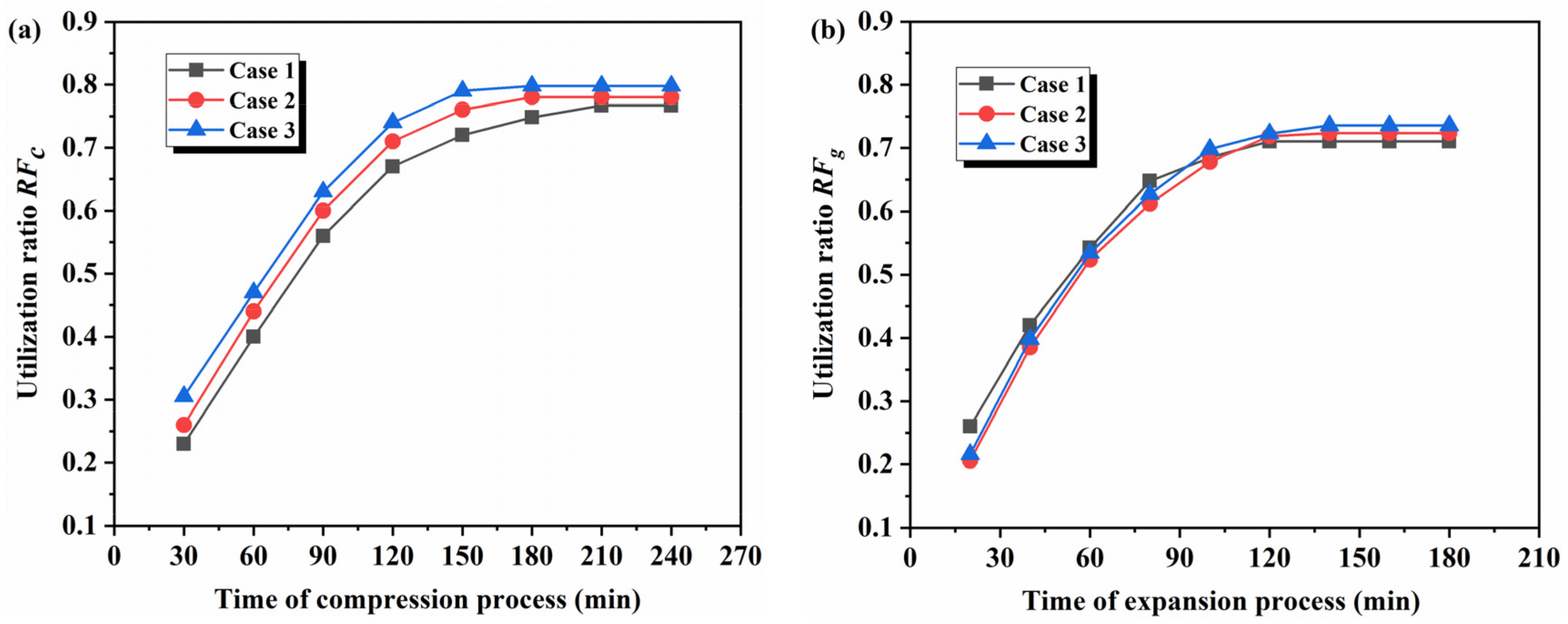
The higher recovery rate of compression heat means the better charging–discharging performance of the designed packed-bed LTES. Two dimensionless factors are defined to reflect the utilization ratio of the capacity of packed-bed LTES during the compression and expansion process. RFc is defined as the ratio of heat stored in LTES and the maximum capacity of LTES during the compression process, while RFg is defined as the ratio of heat released by LTES and the maximum capacity of LTES during the expansion process. They are calculated by the following [11]:
R F c = E s t o r e d E m a x , s t o r e d
R F g = E d i s c h a r g e d E m a x , s t o r e d
E m a x , s t o r e d = m s c p , s T a i n T b i n + m s L
The round-trip efficiency is commonly used to evaluate the overall efficiency of the CAES system during a whole working cycle, and it is calculated by the following [11]:
η R T E = W e x p W c o m
The quantity of air stored in the air tank Mst reflects the potential ability to output power, and it is defined as follows [11]:
M s t = P s t V s t R g T s t
where, Pst, Vst, and Tst represent the pressure, volume, and temperature of the air storage tank.

2.4. Model Validation

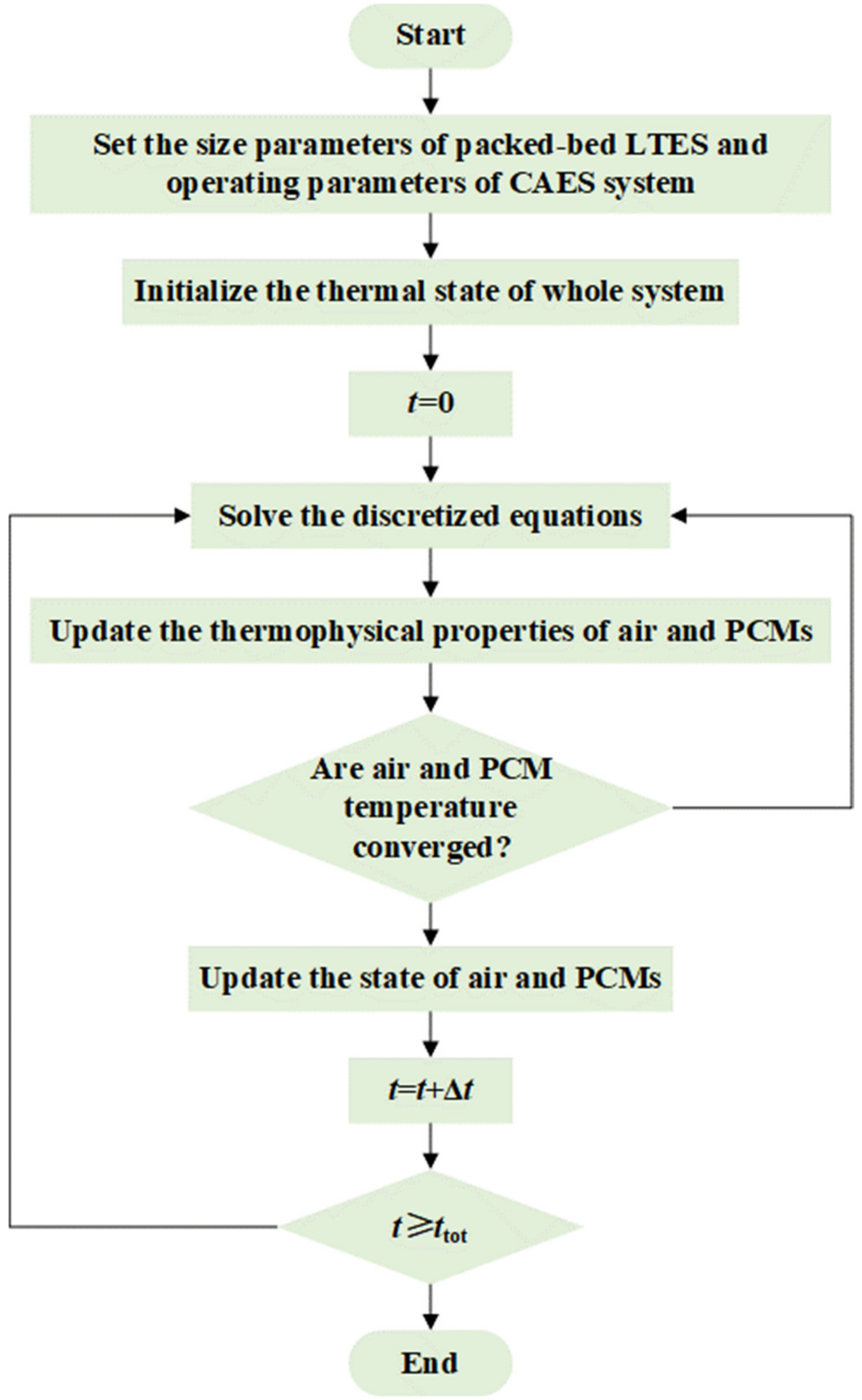
The models of the compressor, the expander, and the air tank are established based on thermodynamic theories, and they are widely validated in scientific communities. Hence, only the dynamic heat transfer model of the packed-bed LTES is validated in this section. The finite difference method is used to solve the model and self-developed codes are created on the MATLAB 2021a platform. The solution procedure is described in Figure 3. The independency of the time step and mesh size were checked and the time step and mesh size were 0.02 s and 0.01 m.
To validate the simulation model, the simulation results are compared with experimental data in reference [37] by using the same packed-bed LTES layouts and parameter settings. In the experiments, the inlet temperature of air was 326 °C while the volumetric flow rate was 110 m3/h. The porosity of the encapsulated PCM balls was 0.345 with an equivalent diameter of 0.0275 m, and the melting temperature of the PCM was 305~307 ℃. The temperature at different locations inside the packed-bed LTES was monitored, and the comparison between the present simulation and reference data is shown in Figure 4. The results show that the temperatures at the second row and eighth row PCM balls agree well with experimental data, and the maximum error between the present simulation and the reference in two locations was 1.77% and 1.63%, respectively. The confidence interval of the error analysis is 95%, which demonstrates the soundness of the solution method used in this study.

3. Results and Discussion

Based on the validated simulation model, the effects of packed-bed LTES with different PCM layouts were initially compared with the performance of the CAES system, and the proper PCM layout in LTES was specified. Then, the dynamic charging–discharging performance was analyzed in detail, based on the selected PCM layout. Finally, the parameters of the selected PCM layout were optimized, using the system performance as the objective.

3.1. Comparion of Various PCM Layouts in Packed-Bed LTES

In this section, three different layouts of PCMs in packed-bed LTES are considered. In Case 1, the packed-bed LTES is filled by only one type of PCM. In Case 2, the packed-bed LTES is filled by two types of PCMs in a cascaded layout based on the order of their melting temperature. In Case 3, the packed-bed LTES is filled by three types of PCMs in a cascaded layout based on the order of their melting temperature. In our previous study [29], the effects of various PCMs are evaluated for the CAES system, and a recommended order list of candidate PCMs is obtained considering the best comprehensive performance of the CAES system. The parameters of the investigated CAES system in this study are kept the same as our previous study [29], and the top three PCMs in the recommended order list are used in this study as shown in Table 2. In Case 1, only P1 is used. In Case 2, P1 and P2 are arranged in an order of melting temperature from highest to lowest. In Case 3, P1, P2, and P3 are arranged in an order of melting temperature from highest to lowest. It should be noted that the proportion of each segment in Case 2 and 3 is considered as equal in this section.
Figure 5 shows the utilization ratio RFc and RFg of packed-bed LTES during the compression and expansion process. It can be observed that Case 3 has the largest RFc of 79.8% and Case 2 (78%) follows at any moment during the compression process; meanwhile, Case 1 has the smallest one at 76.7%. With the increase in PCM segments, a larger temperature difference between the air and the packed-bed LTES can be achieved, leading to a higher charging rate of LTES; thus, more compression heat can be stored in LTES. In addition, the average melting temperature of Case 2 and Case 3 involves PCMs with a lower melting temperature than that of Case 1, which is attributed to the lower average temperature of LTES during the whole compression and holding process. That is, the heat dissipated to the ambient air in Case 2 and Case 3 is smaller than that of Case 1. The combined effects explain the highest RFc, which is that of Case 3. During the expansion process of the CAES system, it can be found that the RFg of Case 1 (73.6%) is higher than that Case 2 (72.3%) and Case 3 (71.0%) at the first half of the expansion process, since the average temperature of LTES in Case 1 is highest and a larger temperature difference forms between the air and LTES; thus, a higher heat transfer rate is associated with a higher heat dissipation to ambient air, leading to the fast decrease in the average temperature of LTES. Therefore, at the latter half of the expansion process, the stored heat in LTES cannot be efficiently released to the air. Due to the better temperature matching between the air and PCMs, Case 3 has a larger final RFg. As for the more noticeable difference between cases during the charging process rather than during the discharging process, the reason lies in the higher inlet temperature of air and longer operation duration during the charging process, leading to the larger deviations of each case.
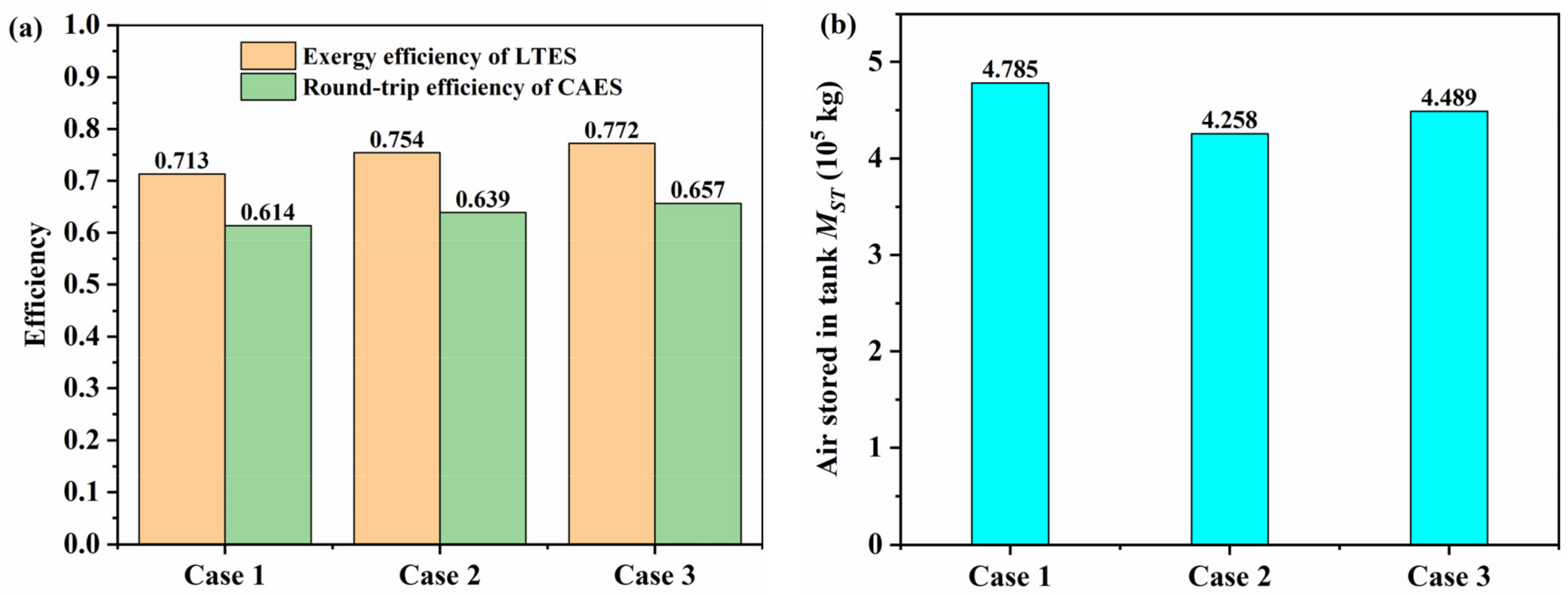
The exergy efficiency of packed-bed LTES, round-trip efficiency, and the total mass of air stored in the air tank are presented in Figure 6. For the exergy efficiency of packed-bed LTES, Case 3 has the largest exergy efficiency of 0.772, which is 8.3% higher than that of Case 1. The reason is attributed to the cascaded layout of PCMs in LTES, achieving better temperature matching performance. The higher utilization ratio of compression heat also leads to the highest round-trip efficiency of 0.657 in the CAES system (Case 3), and it is 6.9% higher than that of Case 1 (0.614). However, the total mass of air stored in Case 2 and Case 3 is a little smaller than that of Case 1, which is related to the thermophysical parameters of PCMs used in three cases. Although the cascaded layout of PCMs can improve the heat stored in LTES during the compression, the P2 and P3 used in Case 2 and Case 3 have significantly lower latent heat compared with P1, leading to the over-charging of later segments of PCM and higher temperature of LTES at the late stage of the compression process. At this stage, the high temperature air has low density. Overall, in a CAES system, the round-trip efficiency is more important. In view of this, it can be concluded that Case 3, with three different PCMs, has a better comprehensive performance, and it will be further analyzed and optimized in the following sections.

3.2. Charging–Discharging Performance of Packed-Bed LTES

Although Case 3 is specified as the proper layout, the parameters in the packed-bed LTES should be optimized based on understanding the limitations of this layout, and a detailed analysis about dynamic operating characteristics needs to be conducted. Figure 7 shows the temperature distribution of air along the flow direction of packed-bed LTES. With the expedited compression process, compressed air releases heat to the PCM balls. It can be found that the air temperature is greatly influenced by the temperature of PCM balls. The overall trend can be observed that the temperature of PCM balls near the inlet of packed-bed LTES rises fast and then slows down. As the hot compression air flows through the LTES continuously, the melting temperature of PCM1 is reached over time, and PCM2 and PCM3 start melting successively. In detail, the PCM balls in packed-bed LTES are solid with a temperature of 290.15 K while the inlet temperature of air is 556.7 K at the initial stage of the compression process. As time goes on, the heat is stored by PCM balls in a sensible form before PCM balls in each stage reach their melting temperature. Later, the PCM balls reach the melting temperature and phase change process occurs with heat stored by the PCM balls in a form of latent heat. After the PCM balls fully melt at each stage, the heat is stored by a sensible process again. At the moment of t = 60 min, the air temperature at the outlet of LTES reaches the ambient temperature, which means the compression heat of air is fully recovered by PCM balls, and the temperature of PCM balls near the outlet of LTES still maintains at the ambient temperature. At the moment of t = 240 min, the air temperature outlet of LTES stays the same as the inlet one, and it indicates that all of the PCM balls have fully melted and are overcharged. That is to say, at the late stage of the compression process, the compression heat cannot be recovered by LTES, leading to higher air temperature at the inlet of the air tank and a smaller mass of air stored in the air tank as discussed before.
The holding stage lasts for 10 h before the expansion process of the CAES system starts. It can be found that the temperature of packed-bed LTES decreases from 556.7 K to 532.4 K due to heat dissipation to the ambient environment. Figure 8 illustrates the temperature distribution of air along the flow direction of packed-bed LTES during the expansion process. The heat transfer occurred in the LTES during the expansion process in the reverse of the compression process. The overall trend can be observed that the temperature of PCM balls near the inlet of packed-bed LTES declines fast and then slows down. As the cold air flows through the LTES continuously, the solidification temperature of PCM1 is reached over time, and PCM2 and PCM3 start solidifying successively. At the moment of t = 180 min, the air temperature along the flow direction stays as 290.2 K, attributed to the full utilization of compression heat stored in the packed-bed LTES from a previous time. That is, air is not heated before flowing into the expander at the late stage of the expansion process, and it restricts the power output of efficiency of the CAES system. It should be noted that the mass flow rate of air during the discharging process is larger than that of the charging process, leading the discharging process to be faster than the charging process.
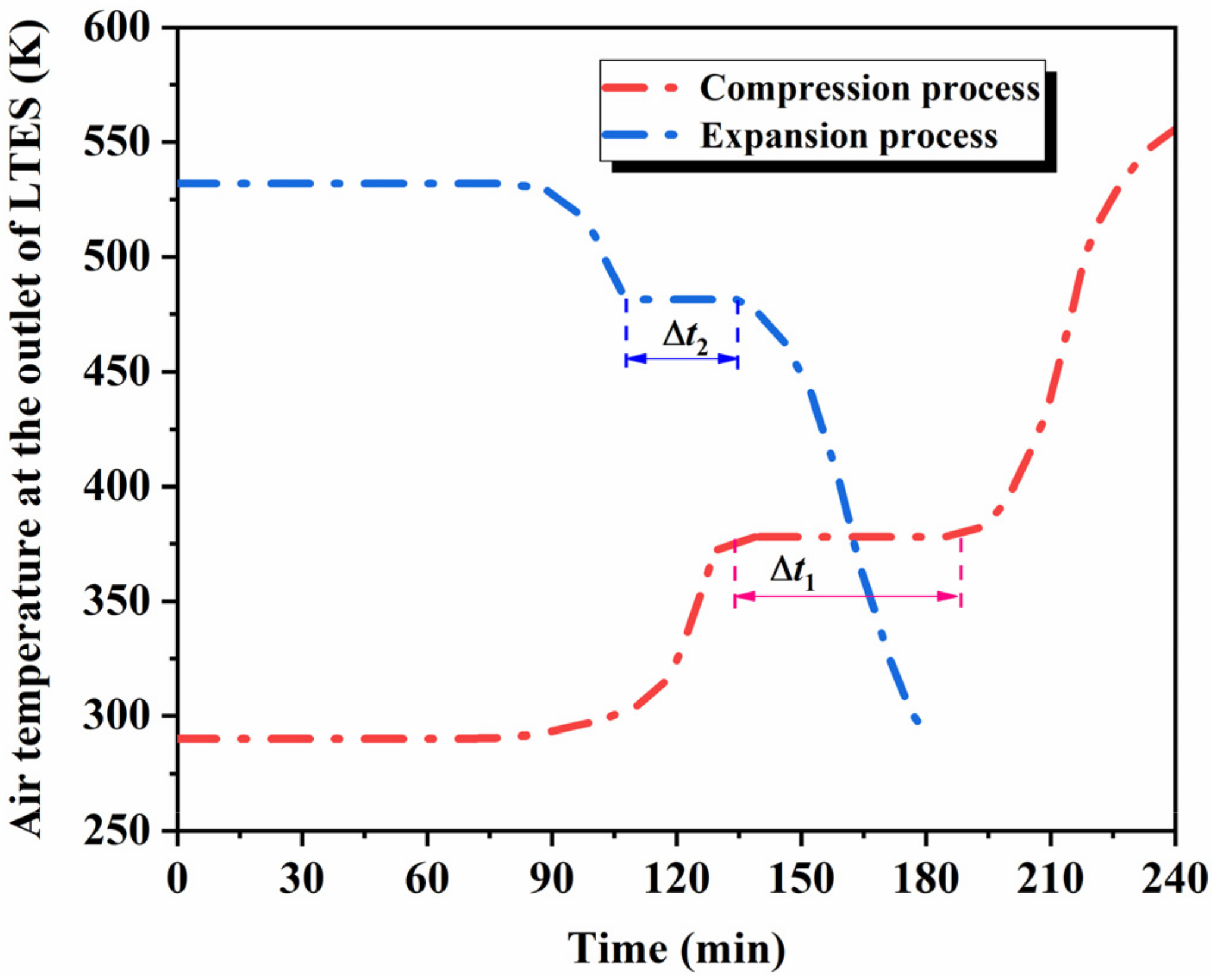
Figure 9 indicates the air temperature at the outlet of packed-bed LTES during the compression and expansion process. For the compression process, the outlet temperature of air stays constant for a period (Δt1) until PCM3 fully melts, and then increases dramatically at the late stage of the compression process as a result of the full melting of all of the PCMs. A similar trend can also be observed that the outlet temperature stays constant for a period (Δt2) until PCM1 fully solidifies, and then it decreases sharply at the late stage of the expansion process resulting from the complete solidification process of all PCMs. For a CAES system, the air temperature at the outlet of LTES should be as low as possible to reduce compression power and store more air in the tank during the compression process, while the air temperature at the outlet of LTES should be relatively higher to improve the expansion power and system efficiency during the expansion process. In view of this, Δt1 in the compression process and Δt2 in the expansion process should be as long as possible. These two parameters are influenced by the proportion of three PCMs in the packed-bed LTES, and they need to be further optimized.

3.3. Proportion Optimization of PCMs in Packed-Bed LTES

Based on the three-PCM layout in the packed-bed LTES, the proportion of three PCMs is optimized in this section. The proportion of PCM1 (A) is defined as the ratio of the height of PCM1 H1 to the total height H, while B represents the proportion of PCM3. Other parameters of the packed-bed LTES are kept unchanged. The effects of proportion A and B on the exergy efficiency of LTES and round-trip efficiency of the CAES system will be analyzed, and the response surface method is used to optimize the proportion A and B.

3.3.1. Response Surface Model

The response surface method (RSM) is a generally used method to improve and optimize multi-variable systems; therefore, it is a suitable method for the investigation of the effects of proportion A and B on the exergy efficiency of LTES and round-trip efficiency. In this method, a second-order model is used to describe the intrinsic relations of two factors and two objectives. A generally used second-order response surface model is described as follows [38]:
y = δ 0 + i = 1 n δ i x i + i = 1 n δ i i x i 2 + i = 1 n j = i + 1 n δ i j x i x j
where, y is the response variable; δ0 is a constant; n is the number of factors; xi and xj are two factors; and δi, δii, and δij are the regression coefficients for the linear term, quadratic term, and their interaction term, and can be obtained by multiple regression.
In this section, the proportion of PCM1 (A) and the proportion of PCM3 (B) are defined as factors, while the exergy efficiency of LTES and round-trip efficiency of the CAES system are defined as response variables. The combination of factors and levels are listed in Table 3. The generated trials and corresponding simulation results are listed in Table 4.
Based on the above trial design and corresponding simulation results, second-order response surface models were established for the exergy efficiency of LTES ηEx and round-trip efficiency of the CAES system ηRTE, respectively. They are described by the following:
η E x = 0.7372 + 0.0767     A + 0.3142     B + 0.3394     A     B 0.1088     A 2 0.9350     B 2
η R T E = 0.5987 + 0.0257     A + 0.6216     B + 0.0381     A     B + 0.1996     A 2 1.3367     B 2
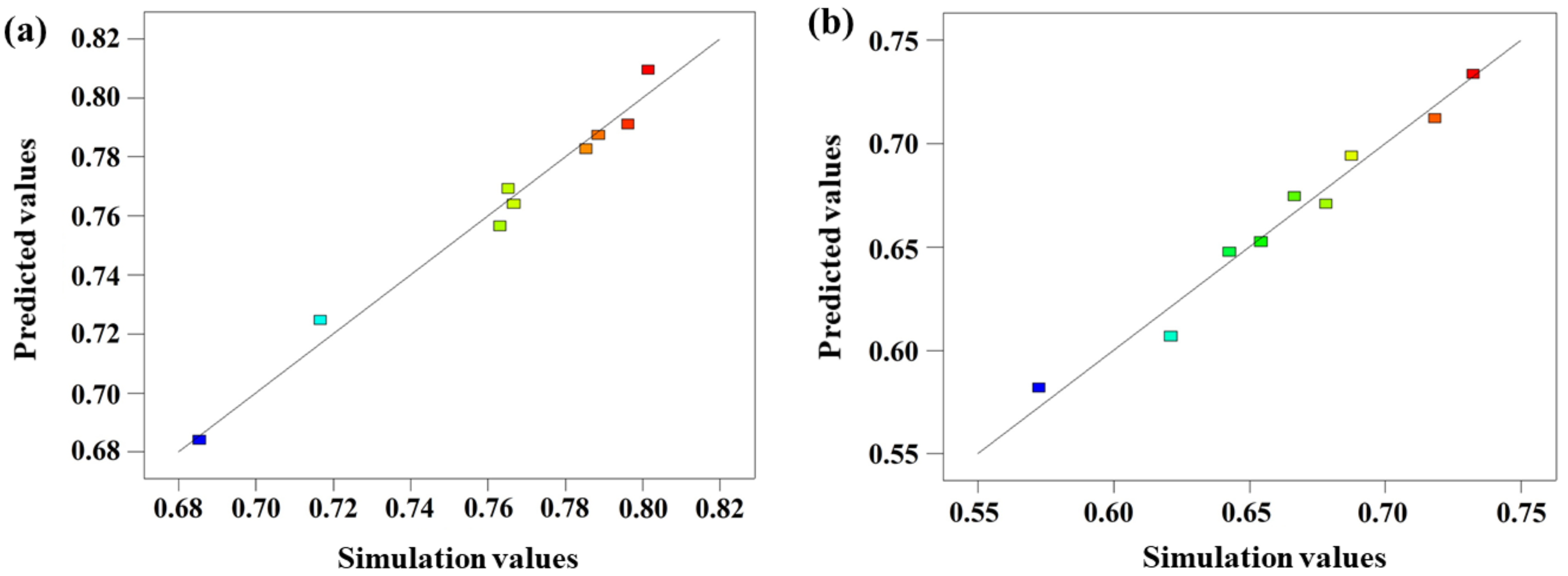
To validate the accuracy of the obtained models, the prediction performance of the models was analyzed. Figure 10 and Figure 11 present the normal distribution of residual errors and prediction accuracy for ηEx and ηRTE. It is apparent that the normal distribution diagram of residual errors has a linear trend for both ηEx and ηRTE, while the prediction values agree well with the simulation values. These results demonstrate the accuracy and reliability of the obtained models, and they can be used for further optimization.

3.3.2. Optimization Results and Analysis

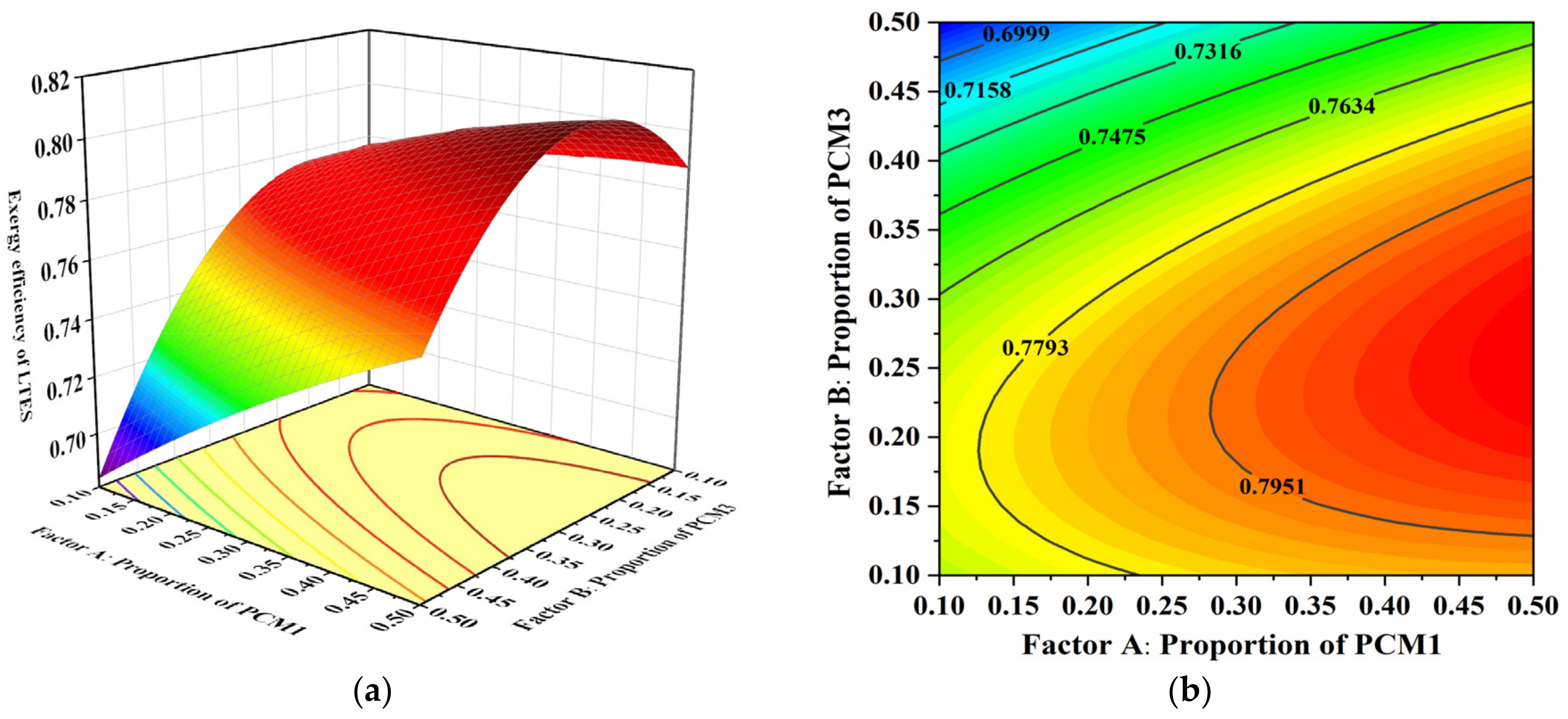
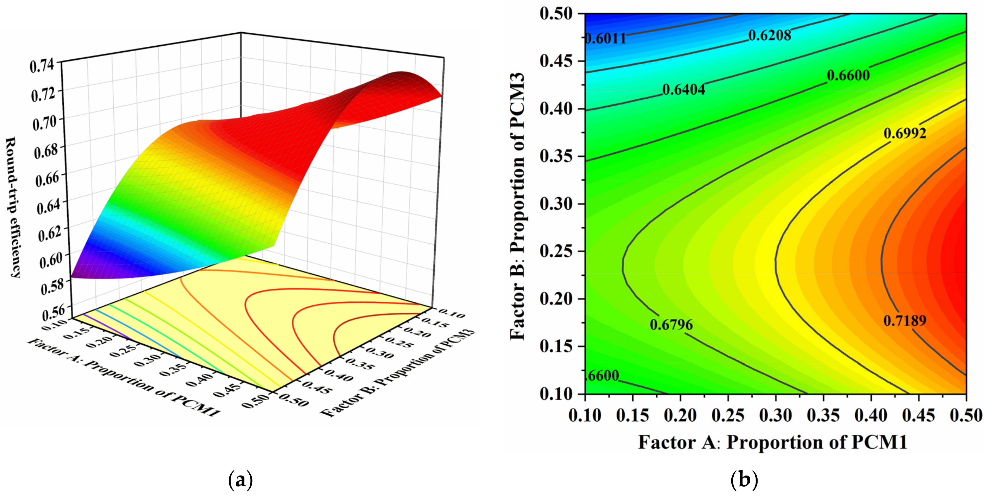
Figure 12 shows the effects of factors A and B on the exergy efficiency of LTES. It can be observed that both factor A and B have significant effects on the exergy efficiency of LTES. In particular, when factor A is within the range of 0.4~0.5 and factor B is within the range of 0.2~0.3, the exergy efficiency of LTES obtains the highest value. In these ranges, the proportion of PCM1 (high melting temperature) is high while the proportion of PCM3 (low melting temperature) is low. The reason lies in the heat transfer process between the air and PCMs. During the compression process, more heat should be stored by the PCM1 with a high melting temperature; the proper proportion of the PCM with a low melting temperature can cause the outlet temperature of air to be at a low state. In the reverse of this, during the expansion process, the outlet temperature of air should be relatively high, that is, the proportion of PCM1 with a high melting temperature should be properly high, and that is consistent with the requirement of proportions of PCM1 and PCM3 in the compression process. The response surface of the round-trip efficiency of the CAES system to factor A and B is depicted in Figure 13. Obviously, the variation in the trend of round-trip efficiency is similar to that of exergy efficiency under different factors A and B, and the reasons are also the same.
To obtain the optimal exergy efficiency and round-trip efficiency simultaneously, multi-objective optimization should be conducted. In the response surface method, an expectation function is used to achieve multi-objective optimization. The predicted optimal factor combination and response by an above second-order response surface model are listed in Table 5. Within the ranges of factor A and B, the predicted maximum exergy efficiency and round-trip efficiency are 80.9% and 73.3% when factor A and B are set as 0.48 and 0.22, respectively.
To validate the accuracy of the predicted results by a response surface model, the factor combination A = 0.48 and B = 0.22 (the proportion of PCM1:PCM2:PCM3 = 0.48:0.3:0.22) were set as the initial condition in a previous simulation model, and simulation results indicated that the obtained exergy efficiency and round-trip efficiency were 82.6% and 74.3%, respectively. The corresponding errors between the predicted values and simulation values were 2.1% and 1.3%, which demonstrates the accuracy of the optimization results of the response surface model. Compared with the exergy efficiency (77.2%) and round-trip efficiency (65.7%) under an equal proportion of three PCMs discussed in Section 3.1, they are correspondingly improved by 7.0% and 13.1% under the optimized proportion of three PCMs.

4. Conclusions

In this study, the effects of packed-bed LTES with different PCM layouts are initially compared with the performance of the CAES system based on the validated simulation model, and the proper PCM layout in LTES is specified. Then the dynamic charging–discharging performance is analyzed in detail, based on the selected PCM layout. Finally, the proportion of PCMs is optimized, using the system performance as the objective. Key findings are concluded as follows:
(1) The three-stage PCM layout in packed-bed LTES achieves an 8.2% and 6.9% higher exergy efficiency of LTES and round-trip efficiency of the CAES system compared with the one-stage PCM layouts. The reason lies in the better temperature matching between the air and PCMs, which contributes to the lower outlet temperature of air during the compression process and higher outlet temperature of air during the expansion process.
(2) In the three-PCM layout of packed-bed LTES, the proportion of each PCM greatly affects the outlet temperature of air during the compression and expansion process of the CAES system, especially the proportion of PCM with the lowest and highest melting temperature at the inlet and outlet of packed-bed LTES, since the PCM at the last stage determines the outlet temperature of air, and the heat transfer process finally affects the proportion of each PCM.
(3) The optimized proportion of the three PCMs is 0.48:0.3:0.22 in a descending order of melting temperature by response surface method. The maximum exergy efficiency of LTES and the round-trip efficiency are 82.6% and 74.3% under such an optimized PCM proportion, and they are improved by 7.0% and 13.1% compared with the equal proportions of three PCMs.
Although this study investigates the effects of multiple PCMs used in a CAES system and provides an optimization method of PCM proportions, it still needs to consider the sensitivity of other important parameters, such as the thermophysical properties of PCMs and operating conditions of the CAES system. Limited by the length of the article, this topic will be fully investigated in our further studies.

Author Contributions

Conceptualization, X.Y. and Z.L.; methodology, W.D.; software, Z.Z.; validation, X.Y. and Y.H.; formal analysis, G.Q.; writing—original draft preparation, X.Y.; writing—review and editing, Z.L. All authors have read and agreed to the published version of the manuscript.

Funding

This research was funded by the “Pioneer” and “Leading Goose” R&D Program of Zhejiang under grant No. 2024SSYS0073, the National Natural Science Foundation of China (NSFC) under grant number 52206027, the State Key Laboratory of Clean Energy Utilization under grant number ZJUCEU2022017, and China Postdoctoral Science Foundation under grant number 2023T160568.

Data Availability Statement

The original contributions presented in the study are included in the article, further inquiries can be directed to the corresponding author.

Conflicts of Interest

The authors declare no conflicts of interest.

References

  1. Li, Z.; Lu, Y.; Huang, R.; Chang, J.; Yu, X.; Jiang, R.; Yu, X.; Roskilly, A.P. Applications and technological challenges for heat recovery, storage and utilisation with latent thermal energy storage. Appl. Energy 2021, 283, 116277. [Google Scholar] [CrossRef]
  2. He, F.; Liu, Y.; Pan, J.; Ye, X.; Jiao, P. Advanced ocean wave energy harvesting: Current progress and future trends. J. Zhejiang Univ.-Sci. A 2023, 24, 91–108. [Google Scholar] [CrossRef]
  3. Suliman, F.E.M. Solar- and Wind-Energy Utilization in the Kingdom of Saudi Arabia: A Comprehensive Review. Energies 2024, 17, 1894. [Google Scholar] [CrossRef]
  4. Fang, J.; Yang, M.; Dong, X.; Luo, T.; Pan, C.; Liu, Z.; Zhang, C.; Wang, H. Electrochemical-thermochemical complementary hydrogen production system for efficient full-spectrum solar energy storage. Therm. Sci. Eng. Prog. 2024, 49, 102501. [Google Scholar] [CrossRef]
  5. Xu, Y.; Zhang, H.; Yang, Y.; Zhang, J.; Yang, F.; Yan, D.; Yang, H.; Wang, Y. Optimization of energy management strategy for extended range electric vehicles using multi-island genetic algorithm. J. Energy Storage 2023, 61, 106802. [Google Scholar] [CrossRef]
  6. Chatzistylianos, E.S.; Psarros, G.N.; Papathanassiou, S.A. Insights from a Comprehensive Capacity Expansion Planning Modeling on the Operation and Value of Hydropower Plants under High Renewable Penetrations. Energies 2024, 17, 1723. [Google Scholar] [CrossRef]
  7. Wang, H.; Wang, F.; Wang, B.; Wu, J.; Lu, H.; Wang, C. Partial flow separation in guide-vane region of large-capacity/low-head pumped hydro energy storage system with horizontal shaft. J. Energy Storage 2023, 71, 108173. [Google Scholar] [CrossRef]
  8. Selvakumar, R.D.; Wu, J.; Alkaabi, A.K. Electrohydrodynamic acceleration of charging process in a latent heat thermal energy storage module. Appl. Therm. Eng. 2024, 242, 122475. [Google Scholar] [CrossRef]
  9. Mitali, J.; Dhinakaran, S.; Mohamad, A.A. Energy storage systems: A review. Energy Storage Sav. 2022, 1, 166–216. [Google Scholar] [CrossRef]
  10. Cacciali, L.; Battisti, L.; Benini, E. Maximizing Efficiency in Compressed Air Energy Storage: Insights from Thermal Energy Integration and Optimization. Energies 2024, 17, 1552. [Google Scholar] [CrossRef]
  11. Ghorbani, B.; Mehrpooya, M.; Ardehali, A. Energy and exergy analysis of wind farm integrated with compressed air energy storage using multi-stage phase change material. J. Clean. Prod. 2020, 259, 120906. [Google Scholar] [CrossRef]
  12. Liu, C.; Su, X.; Yin, Z.; Sheng, Y.; Zhou, X.; Xu, Y.; Wang, X.; Chen, H. Experimental study on the feasibility of isobaric compressed air energy storage as wind power side energy storage. Appl. Energy 2024, 364, 123129. [Google Scholar] [CrossRef]
  13. Niu, J.; Zhang, C.; Li, Y.; Wu, Y.; Sun, H. Design and investigation of cold storage material for large-scale application in supercritical compressed air energy storage system. J. Energy Storage 2024, 75, 109680. [Google Scholar] [CrossRef]
  14. Meng, J.W.T.; Li, J.; Liu, W. Energy storage salt cavern construction and evaluation technology. Adv. Geo-Energy Res. 2023, 9, 5. [Google Scholar]
  15. Wan, M.; Ji, W.; Wan, J.; He, Y.; Li, J.; Liu, W.; Jurado, M.J. Compressed air energy storage in salt caverns in China: Development and outlook. Adv. Geo-Energy Res. 2023, 9, 14. [Google Scholar] [CrossRef]
  16. Wan, J.; Sun, Y.; He, Y.; Ji, W.; Li, J.; Jiang, L.; Jurado, M.J. Development and technology status of energy storage in depleted gas reservoirs. Int. J. Coal Sci. Technol. 2024, 11, 29. [Google Scholar] [CrossRef]
  17. Raju, M.; Kumar Khaitan, S. Modeling and simulation of compressed air storage in caverns: A case study of the Huntorf plant. Appl. Energy 2012, 89, 474–481. [Google Scholar] [CrossRef]
  18. Li, L.; Liang, W.; Lian, H.; Yang, J.; Dusseault, M. Compressed air energy storage: Characteristics, basic principles, and geological considerations. Adv. Geo-Energy Res. 2018, 2, 135–147. [Google Scholar] [CrossRef]
  19. Matos, C.R.; Silva, P.P.; Carneiro, J.F. Overview of compressed air energy storage projects and regulatory framework for energy storage. J. Energy Storage 2022, 55, 105862. [Google Scholar] [CrossRef]
  20. Opitz, F.; Treffinger, P. Packed bed thermal energy storage model—Generalized approach and experimental validation. Appl. Therm. Eng. 2014, 73, 245–252. [Google Scholar] [CrossRef]
  21. Ortega-Fernández, I.; Zavattoni, S.A.; Rodríguez-Aseguinolaza, J.; D’Aguanno, B.; Barbato, M.C. Analysis of an integrated packed bed thermal energy storage system for heat recovery in compressed air energy storage technology. Appl. Energy 2017, 205, 280–293. [Google Scholar] [CrossRef]
  22. Barbour, E.; Mignard, D.; Ding, Y.; Li, Y. Adiabatic Compressed Air Energy Storage with packed bed thermal energy storage. Appl. Energy 2015, 155, 804–815. [Google Scholar] [CrossRef]
  23. Zhao, P.; Wang, P.; Xu, W.; Lai, Y.; Wang, J.; Dai, Y. Off-design performance analysis of a-caes system with two-stage packed bed heat storage unit. Acta Energiae Solaris Sin. 2022, 43, 294–299. [Google Scholar]
  24. Zhou, Q.; Du, D.; Lu, C.; He, Q.; Liu, W. A review of thermal energy storage in compressed air energy storage system. Energy 2019, 188, 115993. [Google Scholar] [CrossRef]
  25. Yu, X.; Jiang, R.; Li, Z.; Qian, G.; Wang, B.; Wang, L.; Huang, R. Synergistic improvement of melting rate and heat storage capacity by a rotation-based method for shell-and-tube latent thermal energy storage. Appl. Therm. Eng. 2023, 219, 119480. [Google Scholar] [CrossRef]
  26. Javaheri, M.; Shafiei Ghazani, A. Energy and exergy analysis of a novel advanced adiabatic compressed air energy storage hybridized with reverse osmosis system. J. Energy Storage 2023, 73, 109250. [Google Scholar] [CrossRef]
  27. Bashiri Mousavi, S.; Adib, M.; Soltani, M.; Razmi, A.R.; Nathwani, J. Transient thermodynamic modeling and economic analysis of an adiabatic compressed air energy storage (A-CAES) based on cascade packed bed thermal energy storage with encapsulated phase change materials. Energy Convers. Manag. 2021, 243, 114379. [Google Scholar] [CrossRef]
  28. Li, R.; Zhang, Y.; Chen, H.; Zhang, H.; Yang, Z.; Yao, E.; Wang, H. Exploring thermodynamic potential of multiple phase change thermal energy storage for adiabatic compressed air energy storage system. J. Energy Storage 2021, 33, 102054. [Google Scholar] [CrossRef]
  29. Yu, X.; Zhang, Z.; Qian, G.; Jiang, R.; Wang, L.; Huang, R.; Li, Z. Evaluation of PCM thermophysical properties on a compressed air energy storage system integrated with packed-bed latent thermal energy storage. J. Energy Storage 2024, 81, 110519. [Google Scholar] [CrossRef]
  30. Gong, Z.-X.; Mujumdar, A.S. Exergetic Analysis of Energy Storage using Multiple Phase-Change Materials. J. Energy Resour. Technol. 1996, 118, 242–248. [Google Scholar] [CrossRef]
  31. Ismail, K.A.R.; Henríquez, J.R. Numerical and experimental study of spherical capsules packed bed latent heat storage system. Appl. Therm. Eng. 2002, 22, 1705–1716. [Google Scholar] [CrossRef]
  32. Guo, W.; He, Z.; Zhang, Y.; Zhang, P. Thermal performance of the packed bed thermal energy storage system with encapsulated phase change material. Renew. Energy 2022, 196, 1345–1356. [Google Scholar] [CrossRef]
  33. Peng, H.; Li, R.; Ling, X.; Dong, H. Modeling on heat storage performance of compressed air in a packed bed system. Appl. Energy 2015, 160, 1–9. [Google Scholar] [CrossRef]
  34. Gonzo, E.E. Estimating correlations for the effective thermal conductivity of granular materials. Chem. Eng. J. 2002, 90, 299–302. [Google Scholar] [CrossRef]
  35. Beek, J. Design of Packed Catalytic Reactors. In Advances in Chemical Engineering; Drew, T.B., Hoopes, J.W., Vermeulen, T., Eds.; Academic Press: Cambridge, MA, USA, 1962; Volume 3, pp. 203–271. [Google Scholar]
  36. Du Plessis, J.P.; Woudberg, S. Pore-scale derivation of the Ergun equation to enhance its adaptability and generalization. Chem. Eng. Sci. 2008, 63, 2576–2586. [Google Scholar] [CrossRef]
  37. Bellan, S.; Alam, T.E.; González-Aguilar, J.; Romero, M.; Rahman, M.M.; Goswami, D.Y.; Stefanakos, E.K. Numerical and experimental studies on heat transfer characteristics of thermal energy storage system packed with molten salt PCM capsules. Appl. Therm. Eng. 2015, 90, 970–979. [Google Scholar] [CrossRef]
  38. Gao, S.; Zhao, Y.; Zhao, X.; Zhang, Y. Application of response surface method based on new strategy in structural reliability analysis. Structures 2023, 57, 105202. [Google Scholar] [CrossRef]
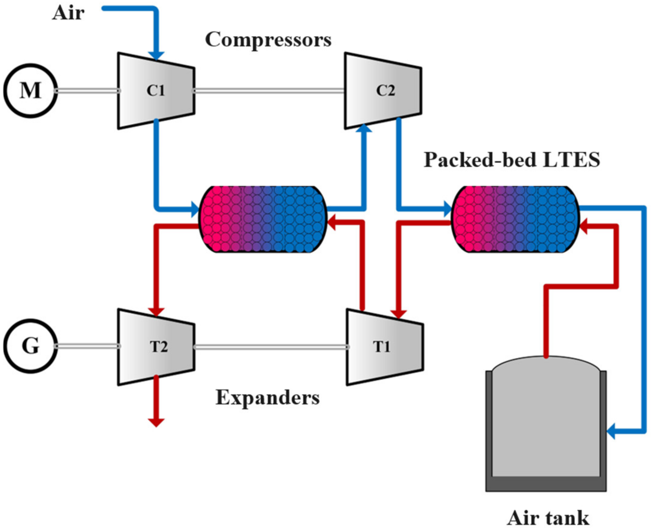
Figure 1. Schematic diagram of the investigated CAES system.
Energies 17 02608 g001
Figure 2. The structure of the packed-bed LTES.
Energies 17 02608 g002
Figure 3. The solution procedures of the packed-bed LTES model.
Energies 17 02608 g003
Figure 4. PCM temperature at different monitoring locations in simulation and reference [37].
Energies 17 02608 g004
Figure 5. Capacity factors of packed-bed LTES under various PCM layouts: (a) charging stage of LTES in the compression process and (b) discharging stage of LTES in the expansion process.
Energies 17 02608 g005
Figure 6. Performance of packed-bed LTES and CAES systems under different PCM layouts: (a) exergy efficiency and roundtrip-efficiency of three cases and (b) quantity of air stored in different cases.
Energies 17 02608 g006
Figure 7. Temperature distribution of air along the flow direction of packed-bed LTES during the compression process.
Energies 17 02608 g007
Figure 8. Temperature distribution of air along the flow direction of packed-bed LTES during the expansion process.
Energies 17 02608 g008
Figure 9. Time-wise temperature of air at the outlet of packed-bed LTES during the compression and expansion processes.
Energies 17 02608 g009
Figure 10. Normal distribution diagram of residual errors for (a) ηEx and (b) ηRTE.
Energies 17 02608 g010
Figure 11. Distribution diagram of predicted values and simulation values for (a) ηEx and (b) ηRTE.
Energies 17 02608 g011
Figure 12. Effects of factors A and B on the exergy efficiency ηEx. (a) Response surface; (b) contour lines.
Energies 17 02608 g012
Figure 13. Effects of factors A and B on the round-trip efficiency ηRTE. (a) Response surface; (b) contour lines.
Energies 17 02608 g013
Table 1. Parameters of the designed packed-bed LTES.
ParametersValuesUnits
Height6m
Diameter2m
Porosity0.4-
Diameter of PCM balls0.02m
Insulator thickness0.2m
Table 2. The thermophysical properties of PCMs used in this study.
No.Selected PCMsTm
(K)
ρ
(kg/m3)
L
(kJ/kg)
cp
J/(kg·K)
λ
W/(m·K)
P1 L i N O 3   87 % N a C l   13 % 481235036915600.63
P2 L i N O 3   62 % N a N O 2   38 % 429229623319100.66
P3Oxalic acid dihydrate378165326428900.70
Table 3. Factors and levels.
FactorsLevels
−101
A (Proportion of PCM1)0.10.30.5
B (Proportion of PCM3)0.10.30.5
Table 4. Design of trials and simulation results.
Trial No.Factor AFactor BExergy Efficiency (%)Round-Trip Efficiency (%)
10.10.376.6767.81
20.10.568.5457.25
30.50.380.1573.23
40.30.379.6268.75
50.30.571.6762.10
60.50.576.3164.26
70.30.178.5466.65
80.10.176.5265.42
90.50.178.8671.82
Table 5. Predicted optimal factor combination and response value.
TermsFactor AFactor BExergy Efficiency (%)Round-Trip
Efficiency (%)
Ranges0.1~0.50.1~0.50~1000~100
Optimal values0.480.2280.973.3
Disclaimer/Publisher’s Note: The statements, opinions and data contained in all publications are solely those of the individual author(s) and contributor(s) and not of MDPI and/or the editor(s). MDPI and/or the editor(s) disclaim responsibility for any injury to people or property resulting from any ideas, methods, instructions or products referred to in the content.