Abstract
In high-penetration renewable-energy grid systems, conventional virtual synchronous generator (VSG) control faces a number of challenges, especially the difficulty of maintaining synchronization during grid voltage drops. This difficulty may lead to current overloads and equipment disconnections, and it has an impact on the security and reliability of the system, as well as limiting the dynamic reactive power support capability of the system. To solve this problem, in this study, a wind–solar hybrid power generation system is designed with a battery energy storage device connected on the DC side, and proposes a low voltage ride-through (LVRT) control strategy for the grid-connected inverter based on an improved VSG. The control strategy employs an integrated current limiting technique combining virtual impedance and vector current limiting to ensure that the VSG exhibits good dynamic power support characteristics during symmetrical faults by adjusting the setpoint value of reactive power. At the same time, it maintains the synchronization and power angle stability of the VSG itself to achieve the goal of LVRT. Simulation results show that the proposed control strategy can effectively suppress the renewable power fluctuations (about 30% reduction in fluctuations compared to the conventional strategy) and ensure the safe and reliable operation of the renewable energy sources and VSGs during grid-side faults. In addition, it provides a given reactive power support and stable grid voltage control (voltage dips reduced by about 20%), which significantly enhances the LVRT capability of the hybrid wind–solar-storage generation system.
1. Introduction
With the introduction of the National “14th Five-Year Plan” and the proposal of the “dual carbon” target, a novel power system primarily utilizing alternative energy sources will be developed, and the new energy sources are becoming more prevalent in the grid. It is crucial to boost the low voltage ride-through (LVRT) capability during fault conditions and improve the grid-side frequency regulation capacity as the use of wind power and photovoltaic systems grows. Thus, today’s power systems are placing significant emphasis on the advancement of a co-generation system that integrates wind, solar, and storage technologies, and key areas of focus include analyzing power output variations, evaluating LVRT capability, and assessing frequency stabilization and control [1].
The development of power grids has resulted in shorter and shorter electrical distances between grids, which makes wind and solar energy storage, which have less inertia on the generation side and the grid side, more susceptible to LVRT from short-circuit faults. The research has indicated that wind power and photovoltaic power generation are important factors in the LVRT process of energy storage systems, as extensively discussed in the relevant literature [2,3,4,5,6,7]. However, there is a scarcity of research on the LVRT approach for a grid-connected system that integrates wind, solar, and storage technologies. In [8], an enhanced self-regulating VSG control system was introduced for doubly fed induction generator wind farms. This system enhanced the overall system by providing frequency support through supplementary control at the grid-side converter, while still maintaining LVRT capability during transient situations; a new and user-friendly overcurrent suppression control method for voltage-controlled VSGs was introduced by the authors of [9] to efficiently mitigate overcurrent issues caused by symmetrical/asymmetrical voltage fluctuations, Yet, there is no improvement in the system’s ability to support reactive power during voltage decreases. In [10], an adaptive LVRT method was proposed. In the compensation voltage control circuit, if the reference value does not match the actual value, the angle output of the active power circuit will be adjusted according to the phase change in the VSG’s active power output. In this way, it is possible to transition smoothly between the normal state and the LVRT state.
However, in the joint grid-connected wind–PV energy storage, for the power generation system that cannot adjust the frequency and voltage well due to low inertia, any of the above measures cannot thoroughly solve the problem, and for this kind of high proportion of new energy grids, the LVRT requirements are more stringent, and more rapid and effective reactive power compensation is needed. Therefore, the typical approaches to solving this issue usually involve utilizing grid-connected inverters controlled by a VSG [11,12,13]. However, in the operation process of traditional VSGs, there are a series of overcurrent problems, which can cause system fluctuations and make it difficult to maintain synchronization during grid voltage dips. In [14,15], the respective authors improved the conventional VSG by introducing virtual impedance and proposing an adaptive reference voltage correction method based on virtual impedance for fault current limitation. In addition, an adaptive term is added to the virtual impedance part, which makes the current limiting method applicable to different operation modes of the microgrid, including grid-connected and islanded modes. In [16,17], the authors used a virtual impedance quantization design approach to achieve overcurrent suppression, but locked the power loop of the VSG, making it difficult to keep the VSG synchronized. In [18,19], an all-pass filter was employed to precisely synchronize the frequency and phase data during grid faults and incorporated damping effects to restrict the magnitude of short-circuit currents, but suffered from power oscillations, poor dynamic stability, and the inability to provide the grid with a given reactive current based on the voltage dip magnitude. In [20], a new control technique for VSGs was introduced, which maintained the power loop to enable the VSGs to operate continuously while also offering improved control of reactive currents, However, the equation of motion of the VSG rotor changes and the process was ignored, which is prone to cause it to disconnect from the grid. In a study detailed in [21], a more advanced dynamic control scheme was suggested for the VSG. This scheme incorporates feedback of the virtual active power at the point of common coupling into the control loop, enhancing the transient stability through the utilization of virtual resistance. Obviously, the control strategies for converters proposed by the majority of researchers have corresponding problems in various aspects and need to be improved.
In summary, this paper presents the contributions relating to the influence of grid-connected wind–solar-storage power generation systems on the grid, as well as the effects of grid-side voltage-drop faults on renewable energy sources, as follows:
1. The integration of energy storage systems with wind–solar hybrid power generation systems, along with the incorporation of a power control loop, enables the more precise and efficient management of energy storage output power and bus voltage. Through the coordinated control of virtual synchronous generators, the system’s inertia and damping characteristics can be enhanced, leading to better wave suppression in wind–solar complementary power generation and increased operational stability of the system.
2. By examining the dynamic responses of a standard virtual synchronous generator in the event of grid short-circuit faults, a thorough current limiting method is suggested. This approach aims to curb both the steady-state and transient inrush currents by upholding the power loop to prevent the current from surpassing the threshold and oscillating. By doing so, it ensures the virtual synchronous generator’s dynamic performance remains intact under both normal and faulty conditions.
3. By adjusting the active and reactive power command values, introducing differential links in the power loop, and adjusting the operating state of the VSG rotor, the VSG has dynamic reactive power support capability while ensuring its synchronization and stability, and injects reactive currents of the corresponding magnitude into the grid side within a specified time, thus improving the FMV regulation capability and realizing the LVRT in the event of system faults.
2. Modeling of Wind–Solar Storage Power Generation Systems and Failure Analysis of Conventional VSGs
According to the hybrid AC–DC regional grid structure of the wind–photovoltaic-storage power generation system [22], it is known that the wind turbines, photovoltaic systems and loads, and the grid are interconnected through the AC bus, and the energy storage system is linked to both the wind power plant and the photovoltaic power plant via a DC busbar, as shown in Figure 1. Various power electronic converters on the AC and DC buses enable the energy sources to interface with the entire system. Among them, the photovoltaic cells link to the DC bus via a DC boost converter, while the wind turbine connects directly to the AC bus through a rotor-side inverter and a grid-side inverter. The energy storage facility is comprised of lithium-ion batteries that are linked to the DC bus using bi-directional DC/DC converters, allowing for energy to flow in both directions.
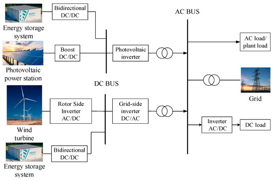
Figure 1.
The hybrid AC–DC regional grid structure.
This part examines tactics for efficiently supervising the synchronized and reliable functioning of local power grids in both regular and transient situations, where wind, solar, and storage systems work together to minimize unpredictable power fluctuations within the grid and enhance the ability to maintain stable voltage levels during electrical faults.
2.1. Wind Storage Modeling and Control
The related literature [23,24] detailed the mathematical model and structural principles of the permanent magnet direct-drive PMSG wind-power generation system. Figure 2 displays the layout of the PMSG wind-power generation system, energy storage, and the integrated control system.
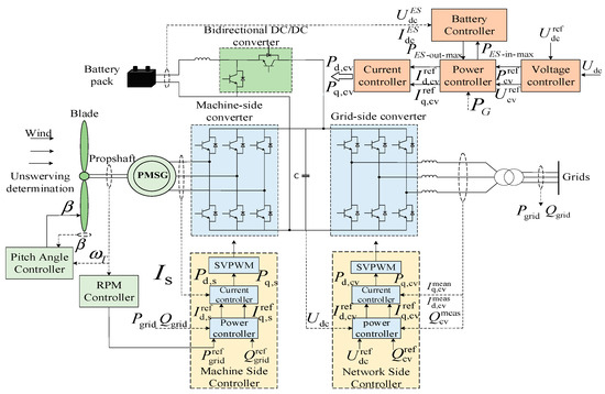
Figure 2.
Wind storage topology and its control system.
In the figure, is the output power of the wind turbine; is the measured rotational speed of the turbine; a and are the measured values of active and reactive power at the grid connection point; , , , and are the measured values of the d and q axis currents under the synchronized rotational coordinates of the machine-side and grid-side converters, respectively; and represent the measured voltage values of the converter’s DC link and the reference value, respectively; and , , , and are the triggering pulses under the synchronized rotational coordinates of the machine-side and grid-side converters in the d and q axes, respectively.
The integration of the energy storage system into a grid-side converter requires the use of a bi-directional DC–DC converter with a battery controller for the energy storage system in the middle and the dynamic regulation of active and reactive power by taking the limiting value of the power reference value , when it exceeds the limit value of the power suction and generation of the battery group; or represent the reference value of the active power of the power controller [25,26].
By incorporating an energy storage system on the DC side, the combined wind power and storage generation system can efficiently control the DC bus voltage and unbalanced power on the power generation side. In steady state, the maximum power output is obtained from wind and solar energy sources, while the energy storage device output is adjusted based on the difference between the new energy production and the load active , which ensures the stability of the output energy to a certain extent; during periods of instability, the energy storage system supplies the necessary power for voltage stability in the VSG and maintains bus voltage stability through inertia power.
In order to achieve a better control effect, the VSG output power tends to present a second-order oscillatory characteristic, the sag power presents a first-order inertial characteristic, and the rotor inertial power is the difference between the two, which exhibits an oscillatory decay characteristic [20]. Therefore, the rotor inertia power and the power of the sagging characteristics are allocated to the energy storage unit that takes into account the higher power density and energy density. The specific power allocation is shown in Equation (1) as follow:
where is the sag power; and are the rated and actual angular velocity of the rotor, respectively; is the rotational inertia; is the tuning coefficient; and is the additional inertia power.
When the power at the bus is unbalanced, the intrinsic speed of the VSG will deviate from the rated value, and both the inertia control and the primary FM will start to act. After receiving the signal, the energy storage unit outputs the power required for primary FM through the Buck/Boost circuit in the bi-directional DC–DC inverter, and indirectly provides the inertia control power by maintaining the stability of the DC bus voltage. At the same time, it also provides a certain reactive power support margin for the VSG, which ensures that the entire system can operate smoothly.
2.2. Optical Storage System Model and Control
Figure 3 displays the photovoltaic storage configuration along with its control system. The MPPT controller of the PV control system provides the active power reference value of the grid-connected inverter, and the inverter’s reactive power reference value is configured based on the system’s power factor needs, and generally is set to 0. The power reference value is compared with the measured values and , and then the outer-loop power controller obtains the reference value and of the inner-loop current control in the synchronous coordinate system. The current control reference value and the measured values of the grid-side currents , are obtained from the current controller by means of the inverter trigger pulses , . Achieving the decoupling control of active and reactive power of inverters and synchronous grid connection can be performed by integrating phase-locked loop measurement methods [27,28,29,30]. The control approach for managing energy storage in photovoltaic systems aligns with the strategy used for controlling energy storage in wind power generation systems.
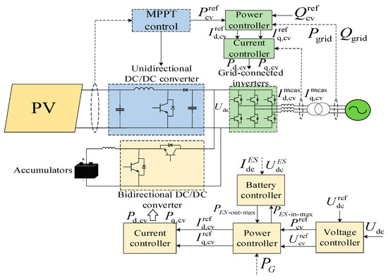
Figure 3.
Optical storage topology and its control system.
2.3. Characterization of Faulty Operation of Traditional Virtual Synchronous Machines
To address issues like low inertia and vulnerability to voltage-drop faults in high-penetration new energy (wind–solar-storage) grid-connected power generation systems, this study implements virtual synchronous machine (VSG) control in the grid-connected inverter, i.e., adding a voltage source converter to the wind–solar-storage co-generation system boosts system inertia, and FM voltage support during grid disturbances, enhancing the system’s low voltage ride-through (LVRT) performance.
Virtual synchronous generator (VSG) technology replicates the functioning characteristics of a synchronous generator through the combination of conventional inverter hardware designs with VSG control methods. Figure 4 depicts the primary circuit structure of the VSG and the corresponding model during a three-phase short-circuit fault in the grid. The main circuit shown in the diagram includes the grid-connected inverter, the DC input power supply, and the line impedance. The controller is divided into two sections: the power frequency controller and the excitation controller. The DC input power supply outputs AC voltage after the inverter, and accesses the grid from the coupling point after the LC filtering line; its DC bus voltage is Udc; in the figure, L is the filtering inductance; C is the filtering capacitance; R is the filtering resistance; Z is the equivalent reactance of the grid line ea, eb, and ec for the three-phase inverter bridge arm voltage; Uoa, Uob, and Uoc for the three-phase inverter output terminal voltage; Uga, Ugb, and Ugc for the grid voltage; ia, ib, and ic for the current flowing through the filter inductor; ioa, iob, and ioc for the inverter output current.
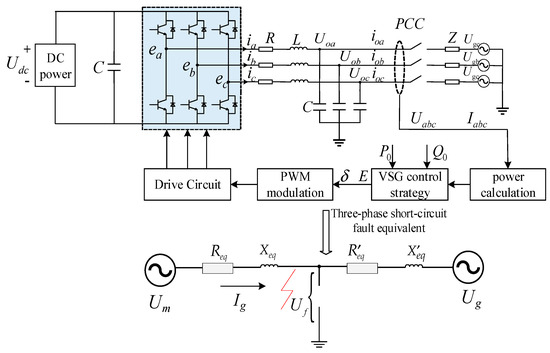
Figure 4.
Overall control block diagram of VSGs.
The voltage at the point of fault during a three-phase short-circuit fault in the grid is influenced by the network characteristics, equipment characteristics, and the severity of the fault, which can be expressed as follows:
where and represent the voltage at the fault point, both before and during the occurrence of the fault; the value of represents the voltage change at the location of the fault (including amplitude and phase change).
During a grid fault, it is acceptable to estimate that the internal potential Um of the VSG remains largely unchanged in terms of both magnitude and phase, yielding the following equation:
The voltage and current characteristics of the virtual synchronous machine adhere to the following fundamental circuit equations when a short-circuit fault happens in the grid, as follows:
where represents the virtual synchronous machine’s output current; + is the equivalent impedance from the virtual synchronous machine to the point of fault; and represents the voltage at the fault location at the time of the fault.
The following equation reflects the expression for the current at VSG when a fault occurs there:
In virtual synchronous generator systems, the impedance of the internal potential at the point of failure is generally low, typically below 0.1 pu, which means that in the case of a fault, the internal potential can be rapidly transmitted to the point of fault and trigger a large amount of fault current. Symmetrical faults are particularly significant when they occur during grid operation; if the fault current is ignored, the fault current may increase rapidly up to several times the rated current. In this case, the fault current may seriously affect the safe operation of grid equipment and even lead to equipment damage or system collapse [31].
Unlike the traditional grid-following type converter, the grid-following type converter has a circuit control to directly suppress fault currents and protect the converter. When an unbalanced drop in grid voltage occurs, the grid-forming converter with VSG at its core can be likened to a voltage source. In this scenario, the VSG acting as a generator model will experience synchronization loss. Due to the low inertia of the VSG, this makes it impossible to quickly regulate the output voltage at a certain point in time, which leads to an instantaneous increase in the output current in some cases. In addition, the power electronic equipment is more limited than the traditional synchronous machine, and the stability of the equipment is weaker when the voltage and current fluctuate. If current limiting measures are not taken, the VSG may trip as a result and may cause damage to the power module. Moreover, if the virtual resistor is utilized to limit the overcurrent without separately addressing the suppression of steady-state current and transient inrush current, frequent switching of the virtual resistor during the fault period will lead to current oscillations. In the distribution network, when a symmetrical short-circuit fault happens, the instantaneous output current overcurrent is caused by an instantaneous drop in the grid voltage. When an asymmetrical fault occurs in the distribution network, such as a single-phase ground fault, the three-phase imbalance of the grid point voltage at this time leads to a three-phase imbalance of the output current of the virtual synchronous generator, and the output of the instantaneous active and reactive power contains a fluctuating component that is two times the grid frequency. The instantaneous power of two times the grid frequency fluctuations through the power ring is reflected in the virtual synchronous generator potential amplitude and phase angle, so that the distortion of the modulating wave ultimately results in potential distortion in the virtual synchronous machine, exacerbating the imbalance of the output current. At the same time, as a result of the conventional virtual synchronous machine on the grid, failures still align with the initial power command output, potentially leading to single-phase or two-phase overcurrent in the steady-state output current.
It is obvious that the traditional virtual synchronous control method has some limitations and cannot significantly optimize the LVRT, which needs to be improved. How to limit the steady-state current and transient inrush current and fast reactive power support to the grid to realize LVRT for the wind–solar-storage co-generation system while maintaining synchronization and dynamic signal stability of the VSG during grid fault is the challenge in the research in this paper.
3. Improvement of Virtual Synchronous Generator LVRT Control Technology
Taking wind turbines as an example, China’s most recent national standard GB/T 19963.1-2021 [32], known as “Technical Provisions for Wind Farm Grid Integration”, stipulates that wind farms should be capable of offering dynamic reactive power support in the event of a three-phase short-circuit fault occurring on the line in the course of grid operation and the voltage at the grid connection point drops below 80% of the rated voltage. And the dynamic reactive power current increment of wind farm should respond to the voltage change in the grid connection point, and satisfy Formula (6), as follows:
where for the wind-farm-injected dynamic reactive current increment; is the coefficient of proportional control of reactive current in the dynamic system of wind farms, value range should not be less than 1.5, and should not be greater than 3; for the wind farm grid voltage standardized value; and for the rated current of the wind farm.
To realize LVRT without removing the new energy units and VSGs during grid faults, it is necessary to limit the fault current of the VSGs and ensure that the VSGs have a certain dynamic reactive power support capability during symmetrical faults. To maintain the superior dynamic support performance of the VSG, on the basis of retaining the traditional virtual synchronous generator power ring, an improved virtual synchronous generator LVRT control technique is used to increase the VSG inertia and damping links to provide the necessary frequency and voltage support for the grid.
3.1. Virtual Synchronous Generator Fault Current Suppression
From Equation (4), it can be inferred that the fault current of the VSG can be effectively limited by either increasing the impedance between the VSG and the fault point or diminishing the voltage difference at the fault point. In this paper, our proposal suggests a comprehensive approach to current limitation by integrating virtual impedance with phase current limiting techniques. Among them, the virtual impedance is related to the increase in the corresponding equivalent impedance and is mainly used to limit the transient inrush current of the VSGs, while the phase current limitation is related to the voltage difference and is mainly used to limit the steady-state fault current of the VSGs.
By introducing virtual impedance, it is possible to enhance the equivalent output impedance of the virtual synchronous machine and alter its output impedance features effectively. The fault current of the VSG can be represented by the following equation in the presence of virtual impedance during a grid fault, ignoring the transient component attenuation characteristics of the virtual synchronous generator:
where is the added virtual impedance.
During the operation of the virtual synchronous machine, if a three-phase short-circuit fault happens at the machine’s end, the estimated equivalent potential impedance from the virtual synchronous machine to the fault is typically the filtered impedance of the generator, which is usually below 0.1 p.u. In the case of considering the filtering impedance, the expression of the fault current of the virtual synchronous machine is changed from Equation (7) to Equation (8).
Therefore, the fault current’s instantaneous value can be represented as follows:
During the most severe faults on the grid, the transient current output from the virtual synchronous generator (VSG) must always remain within the tolerance range, which should typically be less than 1.3 p.u. (i.e., 1.3 times the reference power). This is to ensure that the VSG system can be operated within safe limits and does not impose excessive loads on the grid in the event of a severe grid shock. To effectively restrict the fault current, the corresponding virtual impedance must be adjusted to be above 3 p.u. Increasing the virtual impedance value can effectively raise the impedance of the VSG system towards fault currents, thus limiting its growth and ensuring that it is within the safety range. It is worth noting that the increase in the virtual impedance mode may cause a voltage drop on the normal operating current of the VSG over the virtual impedance, thus affecting the operating performance of the VSG. Therefore, when setting the virtual impedance, the relationship between the impedance magnitude and the dynamic performance of the system needs to be balanced to ensure that the VSG system can operate stably under various operating conditions. To ensure the dynamic stabilization of the VSG, a segmented virtual impedance strategy is used in this section. Specifically, no virtual impedance is put into operation during the normal operating hours of the VSG; the virtual impedance is activated to mitigate overcurrent only when the fault current surpasses the predefined threshold of 1.35 p.u. This segmented virtual impedance strategy can effectively control the fault current during grid faults while maintaining the dynamic performance of the VSG, enabling it to flexibly respond to changes in various grid conditions.
The primary goal of the phasor current-limiting technique is to restrict the fault current by controlling the voltage vector difference between the fault locations and the simulated internal potential of the VSG, in order to stabilize the current fluctuation resulting from casting virtual impedance as much as possible when grid fault occurs. This section utilizes the rotating coordinate system as the reference coordinate system to project the VSG virtual internal potential and output current, which enables the system voltage and current to be represented more intuitively. Under the rotating coordinate system, the voltage gap between the internal potential and the terminal voltage of the converter can be restricted based on the system’s maximum (continuous) current magnitude. This limitation effectively controls the voltage fluctuations in the system and ensures stable operation during normal operation. Additionally, it indirectly restricts the voltage variance between the internal potential and the fault point, which can effectively prevent the system from being damaged or affected by too much or too little voltage.
The output current of the VSG must adhere to the limitations presented in Equation (10) when analyzed under the rotating reference coordinate system.
where and are the maximum continuous operating currents of the dq0 axis in the rotating coordinate system, respectively.
The potential Um inside the VSG meets the criteria outlined in Equation (11), as follows:
3.2. Virtual Synchronous Generator Low Voltage Ride-Through Control Technology
The integrated current limiting method described above effectively restricts the value of the VSG fault current in case of a grid fault. In this section, we are studying methods to guarantee the synchronization and stability of the VSG and its dynamic reactive power support capability during symmetrical faults, and how to be able to inject the corresponding magnitude of reactive power current within the specified time to realize LVRT.
3.2.1. Fast Dynamic Reactive Power Support
China’s latest standards require that when the grid incurs symmetrical faults, the dynamic reactive current increment should meet Equation (6). It is stipulated that the dynamic reactive power current ratio coefficient should not be less than 1.5, and it is preferable for it to be no more than 3, is set to 2. Equation (6) is transformed into the following:
where is the necessary reactive current magnitude during voltage dips and is the output reactive current size before voltage dips.
It follows that the reactive power command should be adjusted in proportion to the corresponding voltage dips, as shown in Equation (13), as follows:
where is the commanded value of reactive power output required for LVRT and the fault point voltage’s d-axis component is denoted as . From Equation (13), it can be seen that adjusting the reactive power command size to make it higher can indirectly inject reactive current to meet the LVRT-related requirements. However, the traditional VSG reactive power control loop is unable to output the specified size of reactive current within the LVRT occurrence time and its response speed is slow, so here the reactive power control loop has been enhanced to accelerate the response time of reactive power by incorporating the PI component [22].
By establishing the magnitude of the active current, the size of the active power command value can be determined at the time of the fault, and according to the reactive current and then solve for the active current, the formula is as follows:
Because the output current has been restricted in the preceding section, there will not be any overcurrent resulting from active current. Hence, it is feasible to sustain a specific level of active power generation by setting a high value of reactive current igq. This helps prevent significant frequency fluctuations caused by insufficient active power and guarantees optimal injection of reactive current while maintaining stable frequency control. Within the control loop of the VSG, the setpoints for active and reactive power commands are adjusted to improve its capacity to boost grid voltage and withstand faults.
3.2.2. Stabilization Control of Rotor Motion Equations
Equation (15) displays the motion equation of the VSG rotor, as follows:
where is the virtual rotational inertia; is the damping coefficient; and , , , are the mechanical torque, electromagnetic torque, rotor angular frequency, and rotor angle, respectively.
In the traditional VSG system, the aforementioned equations are implemented by incorporating two integral links in the control loop. However, in a single-loop scenario, adding such a link can lead to oscillations in the control system when there is a decrease in the grid voltage. In this paper, we explore the idea of incorporating a damping torque to stabilize the motion of the rotor, decelerate changes in the rotor angle, and preserve the synchronization of the VSG in the event of a fault.
If we disregard the losses of the VSG, then the input power of the prime mover is equivalent to its output power, the torque of VSG at this time is the following:
where represents the output voltage. In Equation (16), it is revealed that the torque Te fluctuates greatly with the drop of the grid voltage, and this fluctuation may affect the stabilized motion of the rotor, thus adversely affecting the stability of the system. To stabilize the motion of the rotor, a damping torque in the form of the quasi-differential link of the VSG torque is introduced in this section. The quasi-differential control link has the property of responding strongly to sudden change signals, and utilizes the quasi-differential link in the feedback channel can lead to a smoother output from the controller. When there is a sudden change in the reference input, the quasi-differential link can effectively slow down the rate of change in the controller output, thus maintaining the stability of the system and reducing the torque fluctuation. The inclusion of this quasi-differential link enables the VSG to react more seamlessly to fluctuations in grid voltage or unexpected events, maintaining the stability and reliability of the rotor’s movement. The differential link’s transfer function can be represented as follows:
where and are the time constant of the inertial link and the proportionality constant of the differential link, respectively.
The damping torque is expressed by the following equation:
where represents the gain of the quasi-differential link and represents the time constant of the quasi-differential link.
3.2.3. Power Angle Stabilization
During a grid fault, the grid voltage decreases, and the output active power of the VSG decreases, which is less than the commanded value of the active power of the VSG (equivalent to the mechanical power of a conventional synchronous generator), and the resulting acceleration of the rotor during the transient process of the VSG leads to a rapid increase in its internal frequency and a corresponding increase in the power angle. According to the equal area law [16], when the acceleration area exceeds the maximum deceleration area, it can lead to the transient power angle stabilization issue. If the original power command of the VSG is still followed, the acceleration area and the maximum deceleration area of the VSG are as shown in Figure 5.
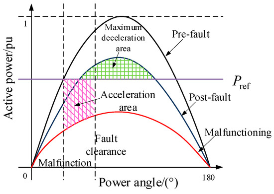
Figure 5.
Acceleration and deceleration motion diagram of the VSG’s rotor under original active power instruction.
Hence, to enhance the transient power angle stability of the VSG and prevent potential deviations within the VSG during grid operation changes, it is crucial to adjust the active power command value for the VSG. When there is a grid fault, the VSG’s active power command value is decreased, so that the acceleration area of the VSG is reduced and the maximum deceleration area is significantly increased, which enhances the transient stability of the VSG itself, as shown in Figure 6. In this paper, the active power command value is adjusted according to during the fault, and the expression is shown in Equation (19), as follows:
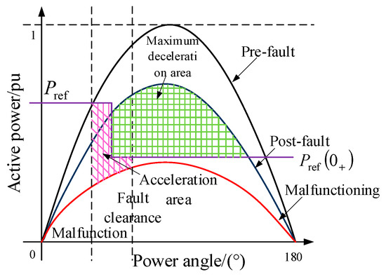
Figure 6.
Acceleration and deceleration motion diagram of the VSG’s rotor with instruction to reduce active power.
The power reference of the VSG is reset when a short-circuit fault occurs during the operation of the grid. Once the fault has been eliminated, the power reference value is reset to its original value without any changes in the control strategy.
4. Simulation Verification
In this section, we validated the stability of wind power combined with energy storage during normal system operation and analyzed the effectiveness of the improved VSG control strategy during LVRT. The example is based on the IEEE 3-machine 9-node system. The wind power and photovoltaic power generation systems are fed into the 220 kV booster station through the 20 kV MV network and are connected to the grid at seven and nine nodes, respectively; the main wiring of the example system is shown in Figure 7; the main parameters of the system are shown in Table 1, which is used in the simulation and analysis of the control strategy by MATLAB R2021a/Simulink; and the simulation diagram is shown in Figure 8.
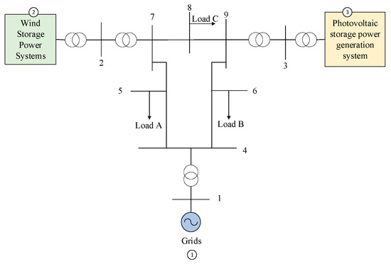
Figure 7.
Single line diagram of the studied power system.

Table 1.
Simulation environment parameters.
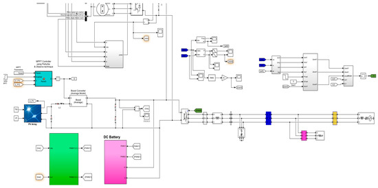
Figure 8.
MATLAB/Simulink model.
4.1. Normal and Stable Operation
The PMD wind turbine, as depicted in Figure 9, utilizes the traditional four wind-speeds model. The initial active output of wind power is 25 kW, the initial active output of the photovoltaic is 30 kW, the energy storage station has a maximum charging/discharging power of 20 kW, the maximum power of energy storage is 300 kW·h, and the minimum power is 3 kW·h. In the simulation stage, its initial power is 18 kW·h, the charge/discharge efficiency is 0.87, and the discharge rate is 0.01. Figure 10 and Figure 11 display the DC bus voltage, as well as the comparison of active and reactive power waveforms of the wind power and photovoltaic power generation system with and without energy storage. This is performed to assess the impact of energy storage on the system during normal operation, and to evaluate its effectiveness in minimizing the effects of new energy inputs on the grid, as well as in regulating power generation from wind and solar sources.
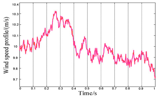
Figure 9.
Wind speed curve.
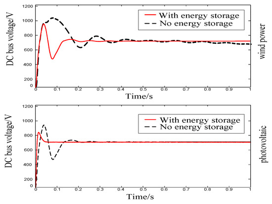
Figure 10.
DC bus voltage characteristics for normal operation of wind/PV stations.
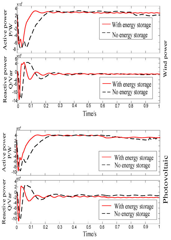
Figure 11.
Normal operating power characteristics of wind/PV stations.
Due to the volatility of wind speed and light, the measured active power P as well as the DC bus voltage at the power station have strong fluctuations up to 12 kW (60%) and 400 V (53%) by 0.4 s, respectively. Under the same environmental conditions, after the energy storage section is integrated into the 750 V DC bus, the power station measures that the active power and reactive power do not fluctuate by more than 5 kW (25%) and 8 kVar (32%), respectively, with no obvious fluctuations in the overall situation, which is relatively smooth. It takes a shorter time to reach a stable output compared to the previous one, which is only 0.1 s, and the DC bus voltage fluctuation is not significant, with a value of around 750 V. The system net-side frequency is shown in Figure 12, and the fluctuation amplitude does not exceed 0.1 Hz keeping within the specified range, but the fluctuation frequency is large.
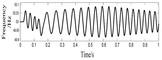
Figure 12.
Normal operation network-side frequency characteristics.
Both photovoltaic and wind power systems are intermittent energy sources that can be influenced by environmental conditions. Therefore, the performance and stability of the power station and DC bus voltage have seen notable enhancements through the operation of charging and discharging with the support of an energy storage system. Thus, utilizing an energy storage system for cooperative control can effectively mitigate power fluctuations.
4.2. Improved VSG LVRT under Symmetrical Faults
To examine the control effectiveness of wind grid-side inverters and photovoltaic grid-connected inverters (both VSC) in three modes of traditional voltage–current double-loop control, traditional VSG control, and enhanced VSG control, along with assessing the functionality of the LVRT control technique of virtual synchronous generators (VSTGs), a 20 kVA virtual synchronous generator (VSTG) model was established for simulation verification in wind/photovoltaic power stations with energy storage systems on the DC side. A symmetrical fault was set up on the grid side at the 0.5 s point, resulting in a voltage drop of 0.5 p.u. and the voltage was returned to its nominal value of 1 p.u. at 1 s. The figures following show the voltage–current behavior of VSGs during symmetrical faults, the voltage characteristics of the wind and solar sides’ DC bus, the active and reactive power output of the grid-connected inverter’s VSC, and the comparison of frequency waveforms on the grid side.
The inverter was designed to handle a steady-state current of 25 A (1.1 p.u.), a maximum inrush current of 30 A (1.3 p.u.), and a minimum reactive current injection of 15 A when the grid drops by 0.5 p.u. in compliance with the national standard. We conducted categorized simulation experiments on the grid-connected inverter’s output voltage and current in order to demonstrate its performance across the three modes of VSG, as shown in Figure 13, Figure 14 and Figure 15, In a symmetrical fault scenario, it is observed that the conventional VSG can produce a peak inrush current of up to 3 p.u., the VSG’s output current also rises to 350 A, exceeding its rated capacity significantly. Subsequently, the current starts oscillating and falling uncoordinated post-fault, failing to meet the low-voltage ride-through requirements. Setting the virtual impedance parameters to Rv = 7.4 and Lv = −1.8 mH enables VSG control of this mode to restrict fault current. As shown in Figure 14, the system experiences minimal fluctuations. However, during a fault event, the current exceeds the limit by 40 A, thus disrupting the system’s normal operation. In contrast, the improved VSG control utilizes a thorough current limiting approach by establishing the virtual impedance current at 8.1 A and the phase current limit at 7.8 A, with no changes in the virtual impedance setting. This approach improves the restraint on fault currents, minimizes variations in the output current amplitude, and maintains balanced currents across all three phases. Figure 16 illustrates the voltage and current waveforms at the grid side with the enhanced VSG operating under this control strategy during a symmetrical fault. The VSG dynamically follows the real-time voltage and current reference commands, ensuring that the reference values closely match the actual measurements, so as to uphold the VSG’s exceptional dynamic support capabilities.
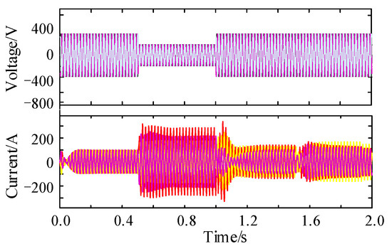
Figure 13.
Conventional VSG control under symmetric failure.
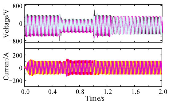
Figure 14.
Virtual impedance VSG control under symmetrical faults.
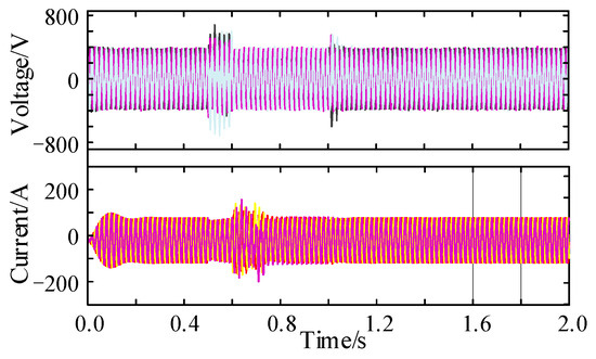
Figure 15.
Improved VSG control under symmetric failure.
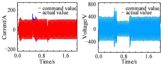
Figure 16.
Improved VSG control command tracking characteristics under symmetric faults.
Figure 17 and Figure 18 show that the lowest DC bus voltage drop with storage-supported regulation remains below 150 V, meeting the system’s LVRT requirement. In contrast, LVRT has a large impact on the traditional VSG control, resulting in DC bus voltage fluctuations of up to 250 V with a 0.1 s recovery time. Furthermore, when the fault occurs, there are substantial fluctuations in reactive power output to the grid side, which can adversely affect the grid-side voltage stability. Although the virtual impedance VSG control promptly returns to the rated value following voltage fluctuations, its power loop response is sluggish, causing inefficient power adjustment. Additionally, the active dip amplitudes can be as high as 17 kW, impacting the grid-side frequency. Moreover, after the fault is resolved, the active power recovery response time is slow. By comparison, the improved VSG control method is more effective than the other two control techniques as it can regulate the DC bus voltage fluctuations within a 50 V range and deliver 10 kVar of reactive power to the grid. This control method ensures that the output current remains stable without causing overcurrent issues or disruptions to the virtual synchronous generator’s grid connection. Additionally, the inclusion of a PI loop enables quick restoration of reactive current for rapid stabilization.
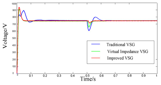
Figure 17.
DC bus voltage characteristics under symmetrical fault.
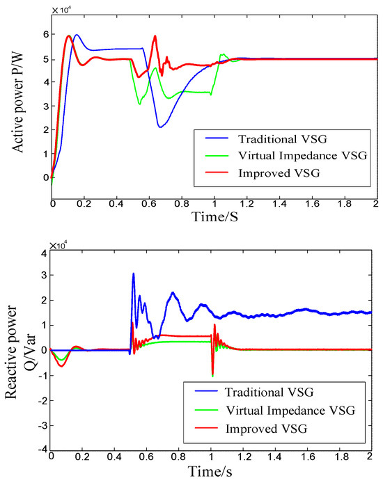
Figure 18.
Power characteristics at VSC of inverter under symmetric fault.
Figure 19 illustrates the impact of frequency control. The improved VSG control model demonstrates swift responsiveness to control commands, efficiently follows the system frequency variations, can deliver increased power support and load rapidly, which greatly enhances the frequency stability in the event of grid faults.
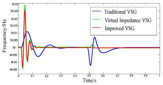
Figure 19.
Network-side frequency characteristics under symmetric fault.
5. Conclusions
This paper introduces a wind–solar-storage combined generation system controlled by a VSG, and suggests an improved VSG control strategy to overcome the limitations of the conventional VSG. The proposed strategy aims to suppress overcurrent in the event of system fluctuations and provide fast reactive power support to the power grid, maintaining the stable operation of the VSG. This paper concludes with the findings from this research:
(1) Wind power and photovoltaic systems both employ a dual-loop control strategy consisting of outer-loop power control and inner-loop current control. This approach enables easy parameter adjustment and offers strong dynamic characteristics and robustness. The energy storage system utilizes a constant voltage and frequency control strategy to regulate the power output. This strategy involves adjusting the voltage and frequency of the grid connection point to manage the energy storage’s power output. It also helps in handling fluctuations in the output of the wind power system and providing support for transient voltage during wind power system failures. Testing various configurations of wind and solar storage systems, along with operation during fault conditions, confirms that the integrated control method effectively mitigates power fluctuations in the wind and solar system. This enhancement in LVRT capability is beneficial for maintaining the secure and steady operation of both the wind and solar storage system and the power grid.
(2) To address the response of the virtual synchronous machine to a short-circuit fault in the grid, we suggest a thorough current-limiting approach that aims to prevent excessive current flow and oscillation. This technique is designed to uphold the VSG’s dynamic performance under both normal and faulty operating conditions. This paper focuses solely on basic studies related to fault current limitations. However, there is still significant work to be accomplished regarding the operation and control of VSGs during grid fault conditions, including developing standards and understanding the interaction between VSGs and traditional power systems.
(3) By adjusting the command value of active and reactive power, introducing a differential link in the power ring, and adjusting the operating state of the VSG rotor, the VSG has dynamic reactive power support capability while ensuring its synchronization and stability. It injects the corresponding size of reactive current into the grid side in the specified time, so as to improve the frequency regulation and voltage support capability in the event of system failure, and realize the low voltage ride-through.
In this paper, only the improvement effect of energy storage and VSGs on the system steady-state transient stability are separately investigated, and the problems of how energy storage can effectively coordinate and cooperate with VSGs on the inverter side under the fault condition to further improve the system stability and power quality still need to be studied in depth.
Author Contributions
Conceptualization, X.L. and J.H.; methodology, X.L.; software, J.S.; validation, X.L., J.S. and J.H.; formal analysis, X.L.; investigation, X.L.; resources, J.H.; data curation, J.S.; writing—original draft preparation, X.L.; writing—review and editing, J.H.; visualization, H.X.; supervision, J.H.; project administration, H.X.; funding acquisition, J.S. All authors have read and agreed to the published version of the manuscript.
Funding
This work was supported by the National Natural Science Foundation of China, grant number 52107095.
Data Availability Statement
The original contributions presented in the study are included in the article, further inquiries can be directed to the corresponding author.
Conflicts of Interest
The authors declare no conflicts of interest.
References
- Saeed, M.H.; Fangzong, W.; Kalwar, B.A.; Iqbal, S. A Review on Microgrids’ Challenges & Perspectives. IEEE Access 2021, 9, 166502–166517. [Google Scholar] [CrossRef]
- Liu, M.; Cao, X.; Cao, C.; Wang, P.; Wang, C.; Pei, J.; Lei, H.; Jiang, X.; Li, R.; Li, J. A Review of Power Conversion Systems and Design Schemes of High-Capacity Battery Energy Storage Systems. IEEE Access 2022, 10, 52030–52042. [Google Scholar] [CrossRef]
- Meng, L.; Zafar, J.; Khadem, S.K.; Collinson, A.; Murchie, K.C.; Coffele, F.; Burt, G.M. Fast Frequency Response from Energy Storage Systems—A Review of Grid Standards, Projects and Technical Issues. IEEE Trans. Smart Grid 2020, 11, 1566–1581. [Google Scholar] [CrossRef]
- Chen, S.; Yao, J.; Liu, Y.; Pei, J.; Huang, S.; Chen, Z. Coupling Mechanism Analysis and Transient Stability Assessment for Multiparalleled Wind Farms During LVRT. IEEE Trans. Sustain. Energy 2021, 12, 2132–2145. [Google Scholar] [CrossRef]
- Gupta, A.P.; Mitra, A.; Mohapatra, A.; Singh, S.N. A Multi-Machine Equivalent Model of a Wind Farm Considering LVRT Characteristic and Wake Effect. IEEE Trans. Sustain. Energy 2022, 13, 1396–1407. [Google Scholar] [CrossRef]
- Mishra, M.K.; Lal, V.N. A Multiobjective Control Strategy for Harmonic Current Mitigation With Enhanced LVRT Operation of a Grid-Tied PV System without PLL Under Abnormal Grid Conditions. IEEE J. Emerg. Sel. Top. Power Electron. 2023, 11, 2164–2177. [Google Scholar] [CrossRef]
- Liu, R.; Yao, J.; Wang, X.; Sun, P.; Pei, J.; Hu, J. Dynamic Stability Analysis and Improved LVRT Schemes of DFIG-Based Wind Turbines during a Symmetrical Fault in a Weak Grid. IEEE Trans. Power Electron. 2020, 35, 303–318. [Google Scholar] [CrossRef]
- Verma, P.; Seethalekshmi, K.; Dwivedi, B. A Self-Regulating Virtual Synchronous Generator Control of Doubly Fed Induction Generator-Wind Farms. IEEE Can. J. Electr. Comput. Eng. 2023, 46, 35–43. [Google Scholar] [CrossRef]
- Koiwa, K.; Inoo, K.; Zanma, T.; Liu, K.-Z. Virtual Voltage Control of VSG for Overcurrent Suppression under Symmetrical and Asymmetrical Voltage Dips. IEEE Trans. Ind. Electron. 2022, 69, 11177–11186. [Google Scholar] [CrossRef]
- Shi, K.; Song, W.; Xu, P.; Liu, R.; Fang, Z.; Ji, Y. Low-Voltage Ride-Through Control Strategy for a Virtual Synchronous Generator Based on Smooth Switching. IEEE Access 2018, 6, 2703–2711. [Google Scholar] [CrossRef]
- Haque, M.E.; Negnevitsky, M.; Muttaqi, K.M. A Novel Control Strategy for a Variable-Speed Wind Turbine with a Permanent-Magnet Synchronous Generator. IEEE Trans. Ind. Appl. 2010, 46, 331–339. [Google Scholar] [CrossRef]
- Nian, H.; Jiao, Y. Improved Virtual Synchronous Generator Control of DFIG to Ride-Through Symmetrical Voltage Fault. IEEE Trans. Energy Convers. 2020, 35, 672–683. [Google Scholar] [CrossRef]
- Fawzy, A.; Bakeer, A.; Magdy, G.; Atawi, I.E.; Roshdy, M. Adaptive Virtual Inertia-Damping System Based on Model Predictive Control for Low-Inertia Microgrids. IEEE Access 2021, 9, 109718–109731. [Google Scholar] [CrossRef]
- Jafariazad, A.H.; Taher, S.A.; Arani, Z.D.; Karimi, M.H.; Guerrero, J.M. Adaptive Supplementary Control of VSG Based on Virtual Impedance for Current Limiting in Grid-Connected and Islanded Microgrids. IEEE Trans. Smart Grid 2024, 15, 89–98. [Google Scholar] [CrossRef]
- Zhang, D.; Xu, H.; Wang, Y.; Chen, L.; Li, Y.; Hu, T. Coordinated Utilization of Adaptive Inertia Control and Virtual Impedance Regulation for Transient Performance Increase of VSG under Different Faults. In Proceedings of the 2021 6th Asia Conference on Power and Electrical Engineering (ACPEE), Chongqing, China, 8–11 April 2021; pp. 838–843. [Google Scholar] [CrossRef]
- Tao, Y.; Wu, F.; Yang, B.; Zhu, S.; Hai, C.; Liu, H. Research on Low-voltage Ride-through Control Strategy of VSG under Symmetrical Grid Fault. In Proceedings of the 2023 8th Asia Conference on Power and Electrical Engineering (ACPEE), Tianjin, China, 14–16 April 2023; pp. 183–189. [Google Scholar] [CrossRef]
- Boonyapakdee, N.; Sangswang, A.; Konghirun, M. Low voltage ride-through strategy for low voltage grid by utilizing resistance and inductance. In Proceedings of the 2016 19th International Conference on Electrical Machines and Systems (ICEMS), Chiba, Japan, 13–16 November 2016; pp. 1–6. [Google Scholar]
- Lang, M. Allpass filter design and applications. IEEE Trans. Signal Process. 1998, 46, 2505–2514. [Google Scholar] [CrossRef]
- Toker, A.; Ozoguz, S.; Cicekoglu, O.; Acar, C. Current-mode all-pass filters using current differencing buffered amplifier and a new high-Q bandpass filter configuration. IEEE Trans. Circuits Syst. II Analog. Digit. Signal Process. 2000, 47, 949–954. [Google Scholar] [CrossRef] [PubMed]
- Xiong, X.; Wu, C.; Blaabjerg, F. An Improved Synchronization Stability Method of Virtual Synchronous Generators Based on Frequency Feedforward on Reactive Power Control Loop. IEEE Trans. Power Electron. 2021, 36, 9136–9148. [Google Scholar] [CrossRef]
- Chen, S.; Sun, Y.; Han, H.; Fu, S.; Luo, S.; Shi, G. A Modified VSG Control Scheme with Virtual Resistance to Enhance Both Small-Signal Stability and Transient Synchronization Stability. IEEE Trans. Power Electron. 2023, 38, 6005–6014. [Google Scholar] [CrossRef]
- Ma, C.; Sun, J.; Huang, J.; Wang, K. Transient Stability Enhancement Strategy for Islanded Microgrids Based on Energy Storage–Virtual Synchronous Machine Control. Energies 2023, 16, 6390. [Google Scholar] [CrossRef]
- Kamiev, K.; Nerg, J.; Pyrhönen, J.; Zaboin, V.; Tapia, J. Feasibility of an Armature-Reaction-Compensated Permanent-Magnet Synchronous Generator in Island Operation. IEEE Trans. Ind. Electron. 2014, 61, 5075–5085. [Google Scholar] [CrossRef]
- Abdelrahem, M.; Hackl, C.M.; Kennel, R. Finite Position Set-Phase Locked Loop for Sensorless Control of Direct-Driven Permanent-Magnet Synchronous Generators. IEEE Trans. Power Electron. 2018, 33, 3097–3105. [Google Scholar] [CrossRef]
- Long, B.; Liao, Y.; Chong, K.T.; Rodríguez, J.; Guerrero, J.M. MPC-Controlled Virtual Synchronous Generator to Enhance Frequency and Voltage Dynamic Performance in Islanded Microgrids. IEEE Trans. Smart Grid 2021, 12, 953–964. [Google Scholar] [CrossRef]
- Schiffer, J.; Seel, T.; Raisch, J.; Sezi, T. Voltage Stability and Reactive Power Sharing in Inverter-Based Microgrids with Consensus-Based Distributed Voltage Control. IEEE Trans. Control. Syst. Technol. 2016, 24, 96–109. [Google Scholar] [CrossRef]
- Liu, L.; Li, H.; Xue, Y.; Liu, W. Decoupled Active and Reactive Power Control for Large-Scale Grid-Connected Photovoltaic Systems Using Cascaded Modular Multilevel Converters. IEEE Trans. Power Electron. 2015, 30, 176–187. [Google Scholar] [CrossRef]
- Rathnayake, D.B.; Bahrani, B. Multivariable Control Design for Grid-Forming Inverters with Decoupled Active and Reactive Power Loops. IEEE Trans. Power Electron. 2023, 38, 1635–1649. [Google Scholar] [CrossRef]
- Jain, S.; Shadmand, M.B.; Balog, R.S. Decoupled Active and Reactive Power Predictive Control for PV Applications Using a Grid-Tied Quasi-Z-Source Inverter. IEEE J. Emerg. Sel. Top. Power Electron. 2018, 6, 1769–1782. [Google Scholar] [CrossRef]
- Yaramasu, V.; Wu, B. Model Predictive Decoupled Active and Reactive Power Control for High-Power Grid-Connected Four-Level Diode-Clamped Inverters. IEEE Trans. Ind. Electron. 2014, 61, 3407–3416. [Google Scholar] [CrossRef]
- Lotfifard, S.; Faiz, J.; Kezunovic, M. Detection of Symmetrical Faults by Distance Relays During Power Swings. IEEE Trans. Power Deliv. 2010, 25, 81–87. [Google Scholar] [CrossRef]
- GB/T 19963.1-2021; Technical Specification for Connecting Wind farm to Power System. State Administration of Market Supervision (SACM): Beijing, China, 2021.
Disclaimer/Publisher’s Note: The statements, opinions and data contained in all publications are solely those of the individual author(s) and contributor(s) and not of MDPI and/or the editor(s). MDPI and/or the editor(s) disclaim responsibility for any injury to people or property resulting from any ideas, methods, instructions or products referred to in the content. |
© 2024 by the authors. Licensee MDPI, Basel, Switzerland. This article is an open access article distributed under the terms and conditions of the Creative Commons Attribution (CC BY) license (https://creativecommons.org/licenses/by/4.0/).