Article

Combustion Characteristics of Sinusoidal-Shaped Walls with Catalyst Segmentation in Micro-Combustors for Micro-Thermophotovoltaic Application

1
College of Energy and Power Engineering, Inner Mongolia University of Technology, Hohhot 010080, China
2
School of Mechanical Engineering, Inner Mongolia University of Technology, Hohhot 010051, China
*
Author to whom correspondence should be addressed.
Energies 2024, 17(11), 2560; https://doi.org/10.3390/en17112560
Submission received: 25 February 2024 / Revised: 11 March 2024 / Accepted: 14 March 2024 / Published: 25 May 2024
(This article belongs to the Special Issue Combustion and Flame: Latest Research)

Abstract

:
The combustion characteristics of micro-combustors significantly impact the performance of micro-thermophotovoltaic (MTPV) systems. This study aims to investigate the effects of sinusoidal-shaped walls and catalyst segmentation on flame stability and combustion performance in a micro-combustor by using numerical methods. The numerical simulation with detailed gas-phase and surface reaction mechanisms is reliable, as the results of numerical simulation align with experimental data. The results show that the interplay between flame stability and sinusoidal-shaped walls is crucial, particularly because of the cavities formed by the sinusoidal-shaped walls of the micro-combustor. The gas-phase ignition position of the sinusoidal-shaped wall combustor moves upstream by 0.050 m compared to the planar-wall combustor, but the flame is stretched. The catalyst segments coated on the crest can shorten the flame length and increase the average temperature by a maximum 62 K, but delay the gas-phase ignition. Conversely, catalyst segments coated on the trough can advance ignition, but this results in flame elongation and a decrease in the average temperature. The rational combination of catalyst segmentation and sinusoidal-shaped walls facilitates moving the ignition position upstream by a maximum of 0.065 m while substantially reducing the length of the combustor required for complete fuel conversion by more than 60%. These attributes are highly beneficial for improving efficiency and minimizing the length of the micro-combustor for MTPV application.

1. Introduction

With increasing demand for micro-electric-powered systems in applications such as micro-drones, micro-robots, and exoskeleton systems, there is an urgent need for compact, lightweight, and high-energy-density power systems. The energy requirements for this micro-electro-mechanical system (MEMS) typically range from 10 to 1000 W [1]. However, limited by the lower energy density of lithium-ion batteries, it is challenging to fully meet the requirements of the MEMS. Therefore, the development of micro-power systems is of great significance. Micro-power-generation systems include micro-thermoelectric system, micro-turbine engines, and micro-thermophotovoltaic systems, among others [2].
The micro-thermophotovoltaic (MTPV) system, distinguished by its absence of moving parts, reduces processing complexity compared to micro-mechanical systems. It features a simple structure, high reliability, and lacks the friction losses associated with moving parts. These attributes make it a power system with great prospects for widespread application. The MTPV system primarily consists of three parts: the combustor, the emitter, and the photovoltaic cell. As the core component of MTPV, the combustor significantly influences the overall system’s performance. For a micro-combustor, a larger surface-to-volume ratio results in increased heat losses, a shortened residence time for the combustible mixture, and a higher likelihood of quenching in a micro/meso-scale combustor, among other unfavorable phenomena. Consequently, improving flame stability and enhancing combustion efficiency in the micro-combustor has become a focal point of research.
To address the issues in micro-combustors, many researchers have proposed various solutions in recent years, and validated and discussed them using experimental and numerical simulation methods. For micro-scale combustion, there are primarily four methods to enhance the flame stability:
  • Heat recirculation
The heat recirculation combustor concept was first proposed by Weinberg and Lloyd [3], and essentially involves excess enthalpy combustion, significantly enhancing the stability of micro-scale combustion. Sitzki et al. [4] studied the micro-scale combustors by constructing and testing macro-scale spiral counterflow heat-recirculating “Swiss Roll” burners. The study found that combustion could be sustained in low-temperature “flameless” mode, even at flow velocities 30 times the stoichiometric laminar burning velocity. Tang et al. [5] numerically found that the overall efficiency of a heat recirculation combustor is almost twice as large as that obtained in a non-recirculation straight channel combustor. Taywade et al. [6] developed an external heat recirculation combustor, and the external heating cup was observed to significantly enhance the flame stability limits. These methods primarily utilize a heat cycle to reduce the heat dissipation, preheat the cool premixed combustible mixture, and achieve excess enthalpy combustion.
2.
Bluff body
Research conducted at conventional scales has indicated that a bluff body can generate a recirculation zone, thereby enhancing the mixing of various components during the combustion process, improving combustion efficiency, and achieving flame stability. Wan et al. [7] investigated the effects of an equilateral triangle bluff body in a planar micro-channel with experimental and numerical methods, and the results showed that the blow-off limit is greatly extended as compared with that of the micro-combustor without a bluff body, widening the operational range of inlet velocity and equivalence ratio. Fan et al. [8] studied the effect of the blockage ratio on the blow-off limit in a planar with a bluff body, and when the blockage ratio was equal to 0.5, it had the maximum blow-off limit.
3.
Porous medium
The combustion process mainly occurs in a gaseous environment. Due to the lower thermal conductivity of gas, convection is the main preheating method. The porous medium greatly enhances the heat transfer of the burned high-temperature gas and unburned mixture through heat conduction, radiation, and convection. Many scholars have studied the combustion characteristics of porous media in micro-combustors. Due to the high thermal conductivity of porous media, the temperature uniformity of the combustor is improved and it has good stable combustion characteristics [9,10,11,12].
4.
Nonplanar walls
The exploration of the impact of multiple obstacles and cavities on the methane conversion rate and the stabilization position of flame in channel combustor was carried out by Chabane et al. [13]. Peng et al. [14] investigated the front cavity in a micro-combustor for an MTPV system. The results showed that front cavity has the ability to improve the flame stability, wall temperature, and combustion efficiency. Wang et al. [15] demonstrated that the flame blow-off limit of the micro/meso-scale channels with wall cavity is much greater than that of planar-wall channels. The backward-facing step structure is a good example of a nonplanar wall that has been implemented to stabilize flames under wide operational ranges in micro/meso-combustors [16,17,18].
The studies available in the literature on wavy wall geometries in micro-combustors are limited. The first study was presented by Bahaidarah et al. [19]. A range of geometric configurations of sinusoidal-shaped wall channels were studied numerically for heat and momentum transfer. The results showed that at high Reynolds number, the heat transfer enhancement ratios of a wavy wall channel were as high as 80% compared to a straight channel. A groundbreaking proposal for MTPV system applications introduced a unique wavy wall micro-channel, as outlined by Mansouri [20]. This research established that the MTPV system’s output power is significantly influenced by the geometry of the micro-combustor and the stability of the flame. Implementing wavy walls in a micro-combustor augments the combustor surface, potentially enhancing the heat transfer characteristics of the system. Moreover, the geometry of the wavy wall significantly influences the location of the flame. Then, Mansouri [21] extended the earlier study using the numerical method to examine the combustion and performance of the wavy wall combustor under various operational conditions, and defined the optimal parameters of the wavy wall for the best operating performance. Han et al. [22] proposed a novel combustor with a smooth outer surface, while the inner wall had a wavy profile. Due to the wavy wall in a micro-combustor, the ammonia conversion rate and flame stabilization limit were increased.
5.
Catalytic combustion
Although the large surface-to-volume ratio of a micro/meso-scale combustor is a challenge for gas-phase combustion, it is advantageous for catalytic combustion. Catalytic combustion exhibits wider stability than gas-phase combustion in a micro/meso-scale combustor [23,24]. The catalytic coating applied to the inner walls of the combustor has the potential to support chemical processes at lower temperatures, even in the face of elevated heat losses. This capability serves to mitigate the consequences of thermal quenching. In catalytic micro-combustors, intricate interactions between gas-phase and surface reactions come into play. Recognized phenomena in these interactions encompass the enhancement of the gas-phase reaction owing to catalytically induced exothermic processes and the suppression of gas-phase reaction resulting from the competition between fuels and oxidizers in the catalyst surface and those in the gas phase. Benedetto et al. [25] demonstrated that the catalytic combustion widens the ranges of operating conditions in a micro-combustor. Li and Im [26] found that catalytic combustion can significantly improve the flame stability under fuel-lean conditions. Karagiannidis et al. [27] investigated the stability limits of a methane-fueled catalytic microreactor in a 1 mm gap channel at pressures of 1–5 bar. The results showed that the stability limits of the catalytic microreactor were wider than those reported for noncatalytic systems. Surface radiation heat transfer greatly impacted the microreactor energy balance and combustion stability. Li et al. [28,29,30] introduced an innovative design concept involving the segment of catalyst coating on cavities for multiple hydrocarbon fuels within a micro-combustor. The combustion characteristics and flame stability were assessed through numerical simulations and experimental methods. This novel design concept integrates the benefits of both gas-phase and surface reactions, and both fuel conversion and flame stability are further improved under a wide range of operational conditions within a micro-combustor.
For the MTPV system, the miniaturization of its core component, the combustor, poses various challenges [31], such as flame instability [31,32,33,34,35], reduced residence time of fuel, and increased heat losses [28,29,30]. In order to advance the application of the MTPV system, it is essential to address its drawbacks. Modifying the structure of the combustor wall seems to be an effective method to address the aforementioned drawbacks. The present study aims to investigate the effect of sinusoidal-shaped wall and catalyst segmentation on flame stability and combustion characteristics for a fuel-lean methane/air mixture in a micro-combustor.

2. Numerical Procedure
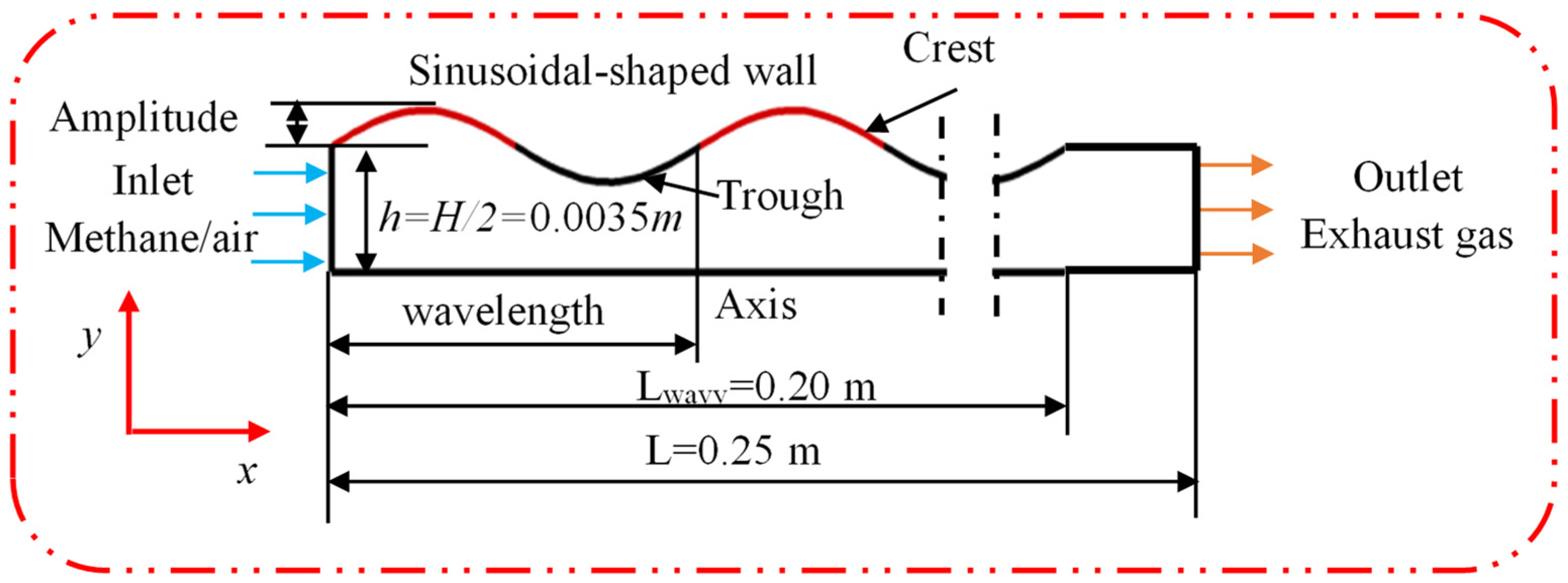
Due to the nature of micro/meso-scale combustors, experimental measurements of internal combustion data are very difficult. To overcome this challenge, detailed numerical modeling can serve as an effective tool for uncovering the combustion phenomena and optimizing designs to achieve the desired performance. In particular, a reliable numerical model is crucial for comprehending the complex interplay of fluid and chemical reactions within these catalytic systems, ultimately leading to a deeper understanding of the combustion process.

2.1. Physical Model

The numerical model employed in this study is based on the experimental configuration described by Dogwiler et al. [32]. The combustor is a rectangular tube, and the dimensions of the experimental combustor are length, L = 0.25 m (x-direction), width, W = 0.104 m (z-direction), and height, H = 2h = 0.007 m (y-direction). Due to the combustor’s width-to-height ratio exceeding 11, a two-dimensional axisymmetric model was employed to reduce computational time, as depicted in Figure 1. The internal volume of the 2D numerical model and the area of inlet and outlet are the same as the experimental combustor. The 2D reactor in this study features sinusoidal walls, A sine wave is used to simulate the sinusoidal-shaped wall of the meso-scale combustors shown in Equation (1).
y = 2 sin 2 π x 0.01256 + h
In our work, six cases were investigated, as shown in Table 1. The combustor walls of Case a are identical to those used in the experimental combustor, both being flat in shape. The primary objective of Case a is to compare simulation results with experimental data to ensure the accuracy of numerical simulation results. In Case b/c/d/e/f, the combustor walls are all equipped with the aforementioned sinusoidal-shaped walls and different catalyst layout. Furthermore, all combustors in the cases have the same area.

2.2. Numerical Model

To address the challenges associated with measuring combustion in small-scale combustors, ANSYS FLUENT 2022 R2 was utilized to simulation the combustion characteristics inside the micro-combustor. This commercial CFD code allows for the incorporation of detailed gas-phase reaction and surface reaction mechanisms in CHEMKIN formats.
Since the maximum Reynolds number being considered is around 186, a laminar steady flow model was used in the numerical simulation. The governing equations of the numerical simulation are composed of two-dimension and steady-state Navier–Stokes equations, including the momentum conservation equation, mass conservation equation, and species continuity equation. The governing equations used in the numerical simulations are presented as follows:
Continuity equation:
ρ t + x j ρ u j = 0
Momentum equation:
t ρ u i + x j ρ u j u i = p x i + x i μ u i x j + u j x j
Energy equation:
ρ D h D t p t = x j λ T x j + x j D ρ Y s x j h s + q
Species mass equation:
ρ Y s t + ρ u j Y s x j = x j D ρ Y s x j + ω s
where ρ is the mass density; t is time; p is the pressure; Y s is the mass fraction of the sth species; h s is the enthalpy species s; D is diffusion coefficient; xj is the molar fraction of species j; u is viscosity; T is the mixture temperature; λ is the thermal conductivity; hs is the specific enthalpy of species j; q is heat of reaction; u j is the velocity vector of species; ωs is the net production rate of the sth species.
The boundary conditions were set as follows. The micro-combustor inlet was assumed as the velocity-inlet boundary with a fixed temperature. The outlet boundary was set to be pressure-outlet, with a fixed gage pressure of 0 Pa. At the micro-combustor walls, no-slip boundary condition and zero-flux diffusion of all species were used. To mitigate the impact of heat loss and radiation from the wall, the wall temperature used in the boundary conditions was obtained by fitting the experimental data of Chabane et al. [13]. All detailed inlet conditions are summarized in Table 2.
The piecewise-polynomial fitting method and Kinetic-theory were employed to calculate the specific heat and viscosity of species, respectively. The specific heat, viscosity/thermal conductivity, and density of methane/air mixture were calculated by mixing-law, mass-weighted-mixing-law, and incompressible ideal gas method, respectively. In addition, the “SIMPLE’’ algorithm was employed to couple the pressure and velocity, and all the governing equations were discretized by a second-order upwind scheme. Continuity equation residual and energy residual values were set to be less than 10−6, while others were set to be less than 10−4 as the convergence criterion.

2.3. Chemical Kinetic Model

Interactions between the gas-phase reaction and surface reaction are complicated; as such, it is not suitable to discuss their effects via the single-step mechanism of the reaction. In this study, for the gas-phase reaction of the fuel-lean methane/air mixture, the detailed gas-phase mechanism by Warnatz et al. [36] was used; it consisted of 108 reactions and 16 species. The applicability range of this mechanism was determined to be 0.05 ≤ φ ≤ 0.5.
For catalytic combustion of methane on platinum, the surface mechanism by Deutschmann et al. [37] was employed, which included 26 reactions and 11 species. The chosen site density (Г) of Pt, set at 2.7 × 10⁻⁹ mol/cm2, accurately represents a polycrystalline surface.
To calculate the species transport properties, the CHEMKIN database is utilized, while the thermal data for the reduced mechanism remained consistent with that used by Warnatz et al. [36].

2.4. Grid Independence

To ensure the accuracy of the simulations, a grid-independent test was conducted as a preliminary step in the analysis. Three different sizes of structured grids were meshed using ANSYS ICEM 2022 R2 software, and with the number of grids: 31,271 (coarser mesh), 90,032 (medium mesh), and 355,067 (finer mesh), and the inlet conditions identical to Case a. The results revealed that the distribution of the OH mass fraction along the axis exhibited a consistent trend with medium and finer mesh, while the coarser mesh exhibited more substantial deviations, as shown in Figure 2. It is noteworthy, however, that increasing the number of grids leads to a significant increase in computational time. Consequently, the medium mesh is deemed most appropriate for this particular study.

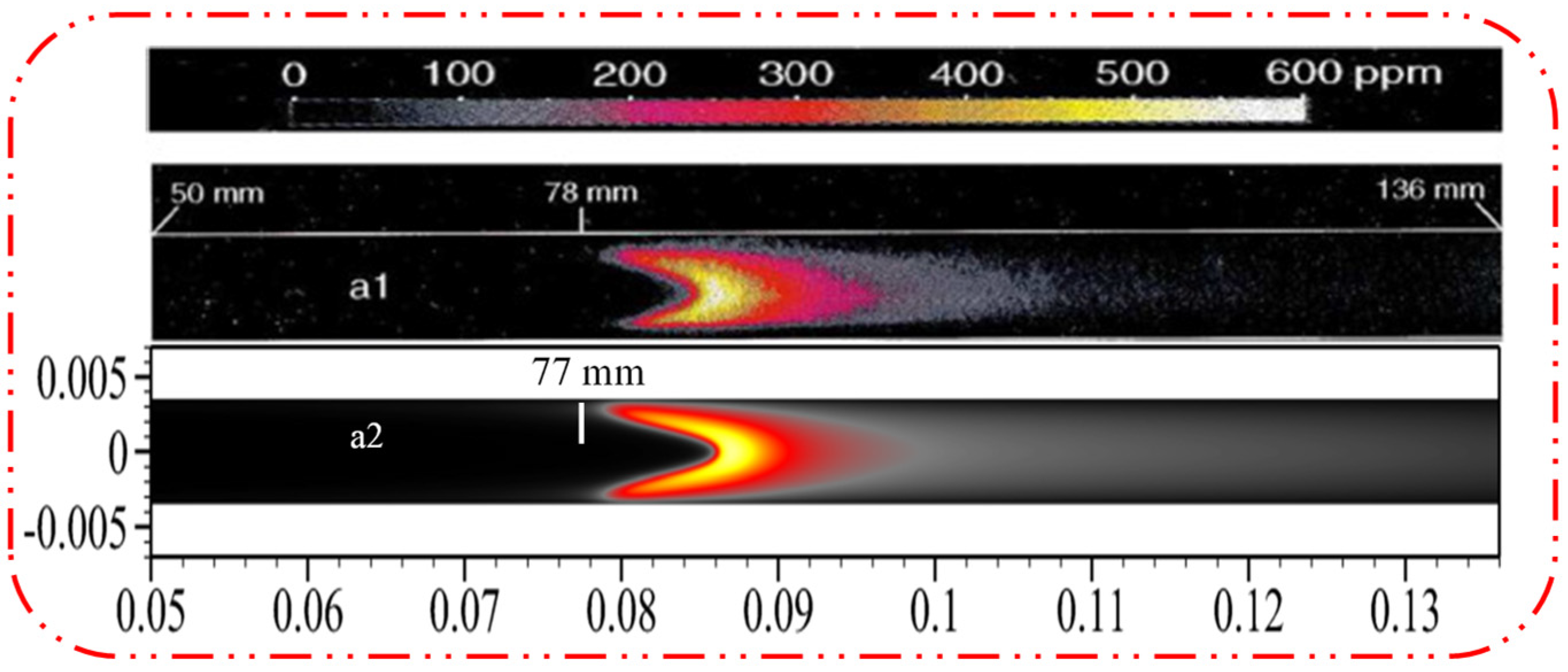
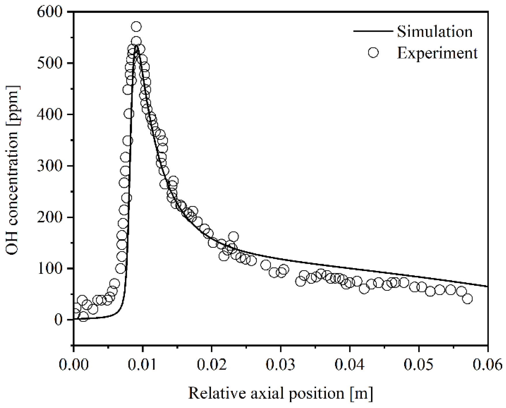
2.5. Model Validation

Comparisons were made between the measured OH concentration maps using planar laser-induced fluorescence (PLIF) (as reported by Dogwiler et al. [32]) and the numerical simulations results, as depicted in Figure 3. The V-flames exhibit excellent stability and reproducibility in terms of their shapes and ignition positions. The sharp rise in OH mole fraction (in ppm) signifies the onset of gas-phase ignition. The measured locations of gas-phase ignition (xig) for Case a, as reported by Dogwiler et al. [32], were 0.078 m. The computed locations of gas-phase ignition for Case a were 0.077 m. The computed locations of gas-phase ignition in this study were slightly underestimated by 1 mm (deviation within ~1.3%). The computed and measured gas-phase ignition positions exhibited good agreement. To further validate the accuracy of the simulation results, a comparison between the simulation and experimental results was conducted for the maximum concentration of axial OH radical and the width of the OH radical concentration zones, as illustrated in Figure 4. To facilitate a comparison of the height and width of the axial OH radical profiles, the computed OH radical profiles were shifted to align with the measured peak OH radical locations. The measured axial mole fraction (in ppm) of OH radical for Case a is 571 ppm [32]. The computed axial mole fraction of OH radical for Case a is 535 ppm. The deviation is within around 6.7%. It can be inferred that the overall performance of the numerical model is considered very good, as the model accurately predicts the gas-phase ignition positions, the levels of OH concentration, and the width of the OH radical concentration zone. This indicates the model’s ability to accurately capture the behavior of the chemical reactions involved in the combustion process.

3. Results

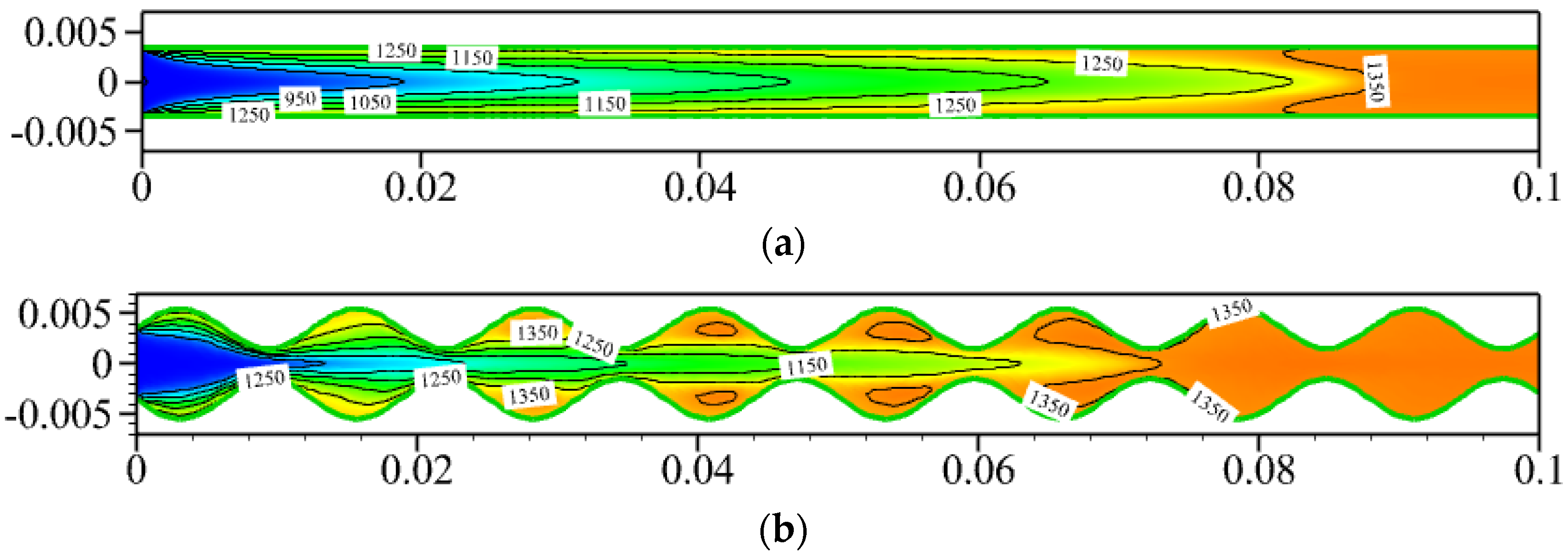
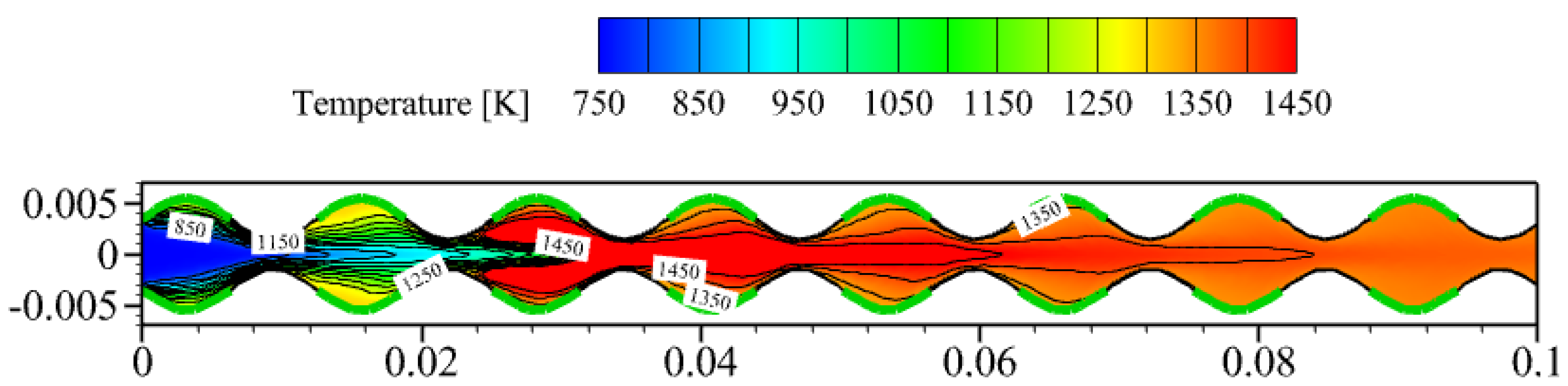
3.1. Effect of Sinusoidal-Shaped Wall

The intricate interplay between the flow of combustible mixtures and chemical reactions underscores the significance of analyzing the influence of sinusoidal-shaped walls on combustion performance in a micro-combustor. In this subsection, the boundary conditions of Case b remain identical to those of Case a.
For hydrocarbon combustion, OH is primarily generated by gas-phase reactions. Thus, the OH radical can typically serve as an indicator of the flame location and heat release zone (high-temperature regions) [38,39]. The left image of Figure 5 shows the OH concentration map of a sinusoidal-shaped wall’s micro-combustor (Case b). Although the inlet conditions and boundary conditions of Case b remain identical to Case a, it can be observed that the ignition position of Case b is located at x = 0.027 m, which is closer to the inlet compared to Case a. However, the flame in Case b is stretched longer than that in Case a.
To achieve stable gas-phase combustion, it is necessary to ensure that the residence time of reactants inside the combustor exceeds their reaction time. Otherwise, incomplete combustion or even flame extinction may occur [31]. Notably, multiple vortices become trapped within the cavities formed by the crests of the sinusoidal-shaped wall, as shown in the right image of Figure 5. These vortices are capable of reducing the flow velocity within the cavities. The flow velocity within the cavities is slower than that in the axial region. This low velocity prolongs the residence time of the reactants, which is beneficial for igniting the gas-phase reaction and stabilizing the flame. The reaction heat and chemical radicals generated by surface reaction can subsequently induce the downstream gas-phase reaction and stabilize the flame in the cavities [28]. Therefore, the gas-phase reaction in Case b is ignited closer to the inlet compared to Case a. Due to the sinusoidal-shaped wall resembling convergent–divergent nozzles, those result in a very high velocity of combustible mixture in the axial region. The high flow velocity compels the combustible mixture to move downstream, so the flame is stretched.
For stable combustion conditions, the mean reaction rate estimated independently from both OH-PLIF and OH chemiluminescence measurements showed good agreement, thereby indicating confidence in using the OH mole fraction to extract the local gas phase reaction rate [35]. The maximum mole fraction of OH radical in Case a is 476.5 ppm, while in Case b, it is 510.6 ppm. This indicates that the gas-phase reaction rate in Case b is slightly higher than that in Case a. The combustor inner average temperature is calculated as follows:
T a v e = A i T i A i
where Ai is the area and Ti is the temperature of inner cell i, respectively. Thus, according to Equation (6), the average temperature of Case a is 1259.9 K, while in Case b, it is 1316.2 K. The latter has a slightly higher internal average temperature, corresponding to the abovementioned slightly higher gas-phase reaction rate in Case b compared to Case a.
As mentioned in Section 2.2, Case a and Case b have the same area. In Case a, the area of the high-temperature region (>1000 K) is 0.00081 m2, while in Case b, the area is 0.001014 m2. The high-temperature area in Case b is 25.2% larger than that in Case a, as shown in Figure 6. Radiative energy is proportional to the fourth power of the outer wall temperature. The larger high-temperature area in Case b has significant advantages for MTPV system application; the high-temperature region can increase the output of radiative energy, thereby improving the efficiency of photovoltaic cells. Moreover, due to the larger surface area of the sinusoidal-shaped wall compared to the planar wall, the radiation energy and convection heat transfer from the outer surface of sinusoidal-shaped wall also increases. This is beneficial for micro-thermophotovoltaic systems.

3.2. Effect of Catalyst Segmentation

Notably, previous research conducted by Chen et al. [40] demonstrated the effective enhancement of flame stability by introducing catalyst segments coated on the inner wall surface in a micro-combustor. Building upon these insights, this section investigates the combined effects of catalyst segments and sinusoidal-shaped walls on flame stability and analyzes their underlying mechanism.
The ignition position of the catalyst segment coating combustor (Case c) is around 0.023 m, as depicted in Figure 7. Compared to the catalyst full coating combustor (Case b), the ignition position of Case c is closer to the inlet. Additionally, the concentrated distribution of the OH radical formed a V-shaped flame, and the maximum mole fraction of the OH radical is 1909 ppm. The concentrated distribution of OH radical indicates intense combustion and a shorter flame distance in Case c. The flame stabilization effect achieved by catalyst segments coated on sinusoidal-shaped walls is highly significant. The reason why catalyst segmentation can stabilize the flame is due to the periodic weakening of the surface reaction rate. As surface reactions mainly consume fuel through diffusion, the catalyst coated on the crest, away from the axis region, makes it challenging to adsorb a sufficient amount of combustible mixture, thereby weakening the surface reaction rate. Under the combined effect of these two factors, the intensity of the surface reaction weakens. The attenuation of the surface reaction inhibited the competition between surface reaction and gas-phase reaction for combustible mixtures, promoting an increase in the gas-phase reaction rate. Thus, the average temperature in Case c is 1342.2 K, which is 26 K higher than that in Case b, and the high-temperature area of Case c is 0.001015 m2; this clearly indicates that the high-temperature area in Case c is larger than that in Case b, as a comparison between Figure 6 and Figure 8 shows.
The combination of catalyst segmentation and sinusoidal-shaped walls greatly improves the flame stability and combustion performance in a micro-combustor. These characteristics are highly advantageous for reducing the length of the combustor, thus providing feasibility for further miniaturization of the combustor.

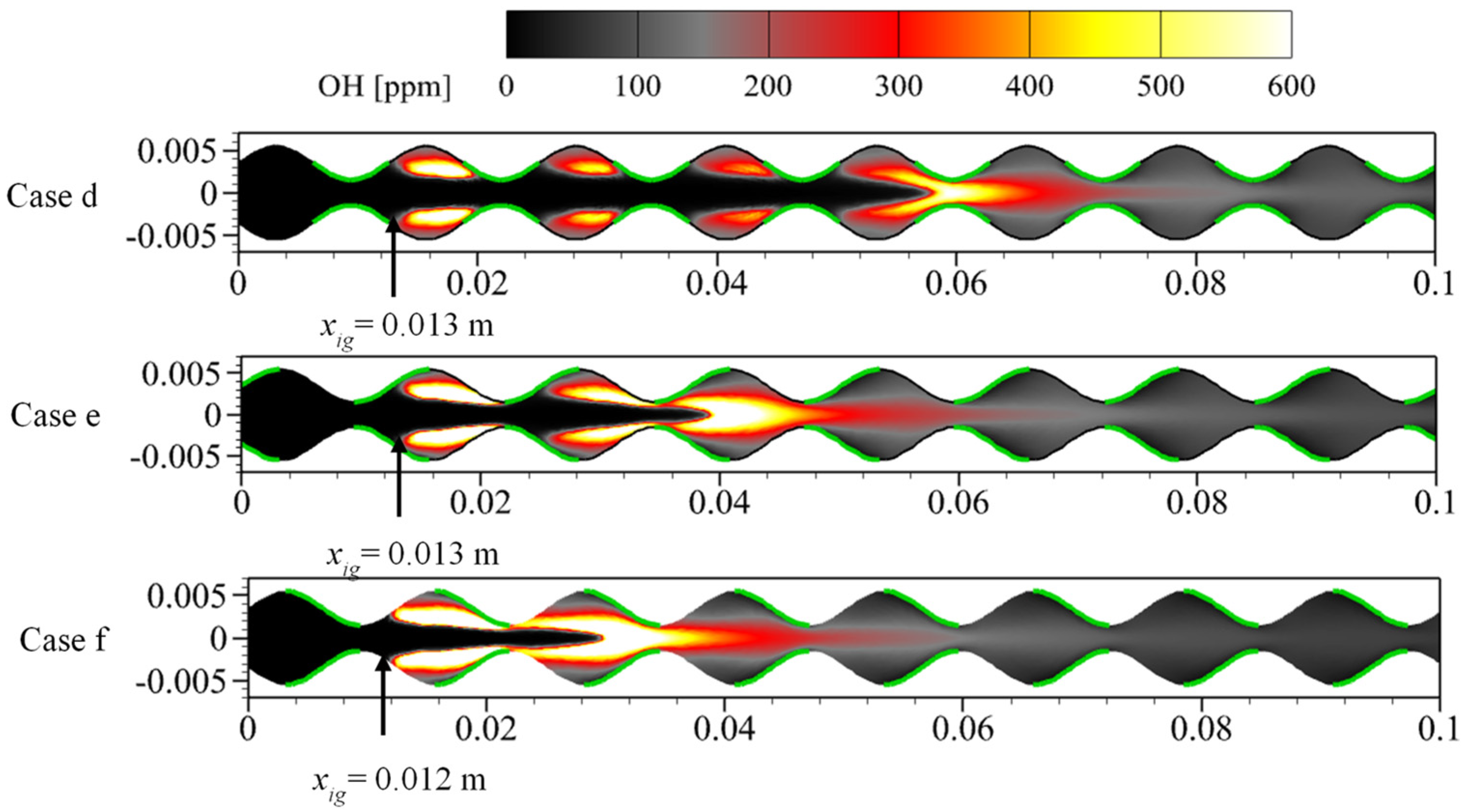
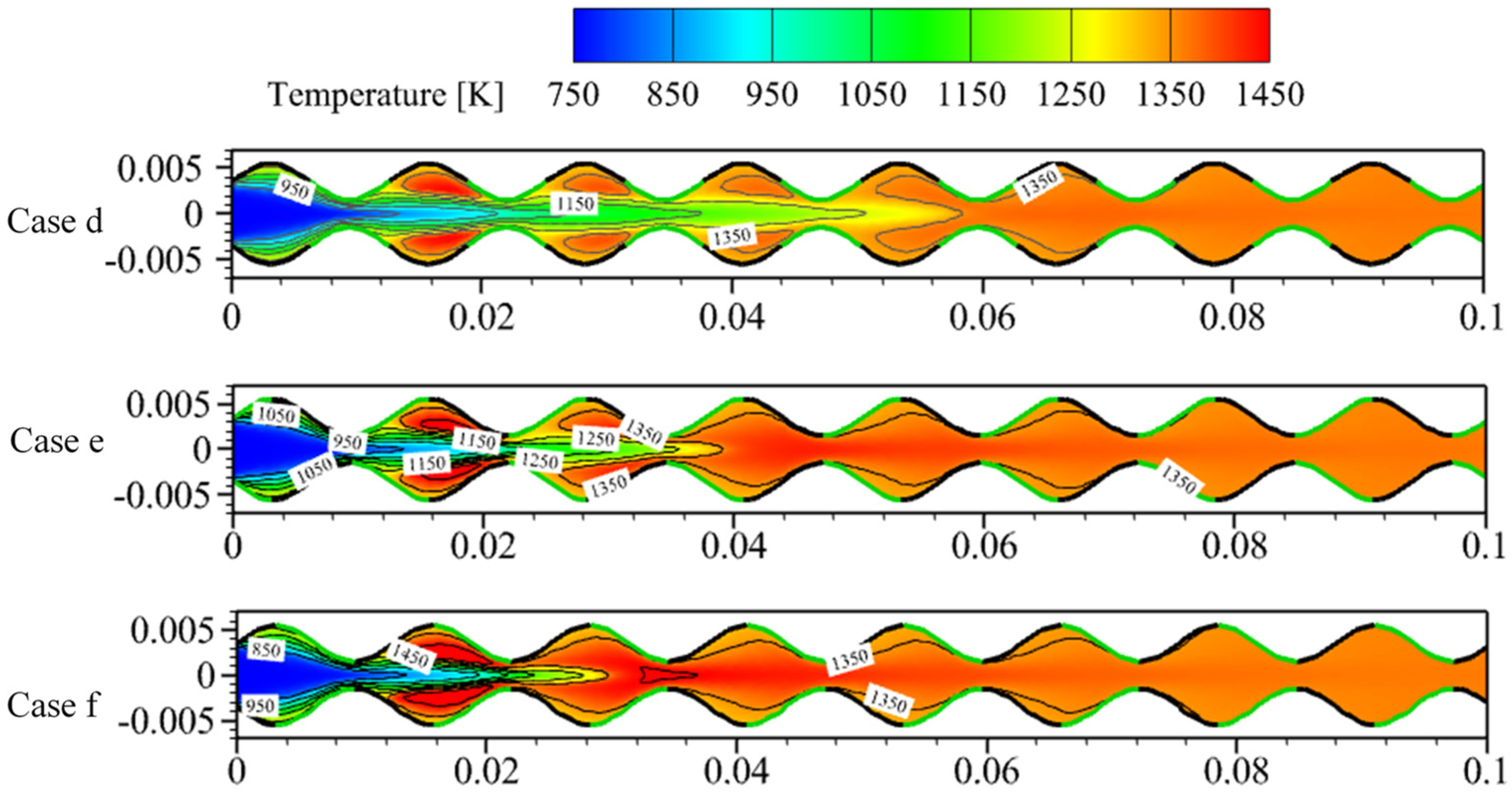
3.3. Effect of Catalyst Segmentation Layout

As described above, catalyst segmentation coated on the sinusoidal-shaped wall can further enhance the flame stability and improve combustion performance in a meso-scale combustor. Combined with Case c, the effect of catalyst segments coated at different positions of the sinusoidal-shaped wall are investigated in this section. The remaining three catalyst segmentation coating layouts are as follows: Case d: the catalyst segments coated on the trough; Case e: the catalyst segments coated on the half of the trough-crest; Case f: the catalyst segments coated on the half of the crest-trough. The length of the catalyst is kept consistent in the four cases, and inlet conditions are the same as Case a.
As mentioned in Section 3.2, surface reactions mainly consume fuel through diffusion. A catalyst coated on the trough of sinusoidal-shaped wall is closer to the axis region, making it easier to obtain more combustible mixtures. Thus, surface reaction will be enhanced, resulting in more reaction heat and chemical radicals. These heat and radicals can easily ignite the gas-phase reaction in the downstream cavities. As shown in Figure 9, the ignition positions of Cases d, e, and f are essentially the same (approximately 0.012 m), which is closer to the inlet than that of Case c. Although catalyst segments are only coated on half of the trough in Cases e/f, it further demonstrates the sensitivity of the ignition position to the catalyst coated on the trough, while catalysts coated on the crest have the least impact on the ignition position.
Although catalyst segments coated on the trough can advance ignition, due to the lower gas-phase reaction intensity, the mole fraction of OH radical and average temperature in Case d is lower than Cases c, e, and f, as depicted in Table 3. In these four different catalyst segment layouts, Case c has the highest average temperature. The areas of high-temperature (>1000 K) regions in Cases d, e, and f are 0.001090 m2, 0.001020 m2, and 0.001022 m2, respectively. Thus, the area of high-temperature zone in Case c is smaller than other cases, as shown in Figure 10. However, the differences in average temperature and area of high-temperature zones among these four cases are not significant. This is because of the ignition position being farther downstream. Therefore, to obtain good combustion performance, it is necessary to balance the gas-phase reaction and surface reaction. The catalyst segments coated on the half of the crest-trough can integrate the advantages of gas-phase and surface reactions to enhance the combustion performance and to promote complete combustion in a short distance, as shown in Figure 11.
Table 3 systematically presents the combustion performance of the six cases. It can be observed that the maximum mole fraction of OH radical is positively correlated with combustion average temperature Tavg. The higher the mole fraction of OH radical, the higher the average temperature.
As mentioned above, the reduced distance for complete methane conversion decreases the requirement for combustor volume, which is beneficial for further miniaturization of the combustor for MTPV application. Thus, to quantitatively evaluate the effects of the six cases on the combustor length, the following Equation (7) is used to calculate the percentage reduction in the length of the combustor required for complete fuel conversion Pmcc (with Case a as the reference):
P m c c = x m c c x m c c , a x m c c , a × 100 %
where xmcc is the methane complete conversion position. The effect of sinusoidal-shaped walls (Case b) on the length of combustor required for methane complete combustion is relatively small, with only about a 16.85% reduction compared to a planar-wall combustor (Case a). However, with the rational combination of sinusoidal-shaped walls and catalyst segments coating layout, it is possible to significantly reduce the length of the combustor. Case c and Case f demonstrate promising potential for miniaturization of the combustor, as they can reduce the length of the combustor by over 60%.

4. Conclusions

In this study, the impact of sinusoidal-shaped walls and catalyst segment in a micro-combustor for the MTPV system application on flame stability and combustion performance was assessed by utilizing a 2D numerical model. The numerical method was coupled with detailed gas-phase and surface reaction mechanisms for fuel-lean methane/air mixture, and was validated with experimental data from the literature.
The main findings are summarized as follows:
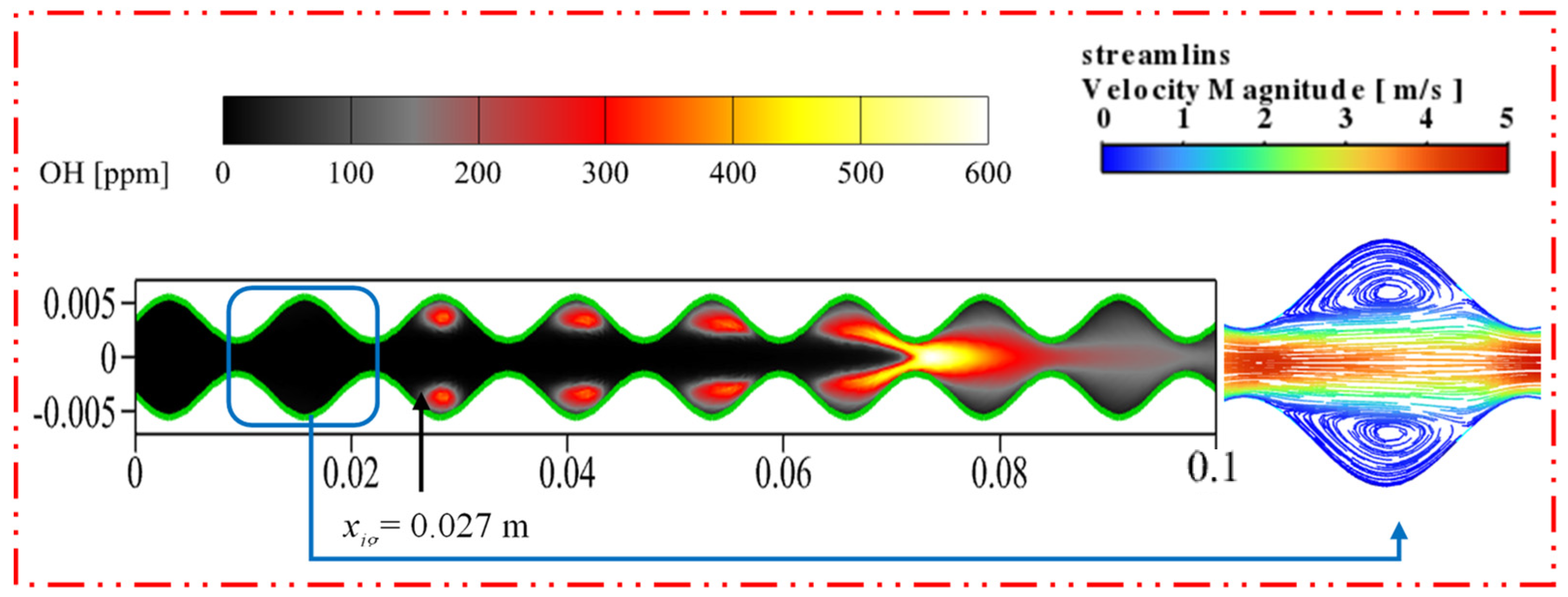
  • The cavities formed by the sinusoidal-shaped walls are highly favorable for the gas-phase reaction, as combustible mixtures in these cavities ignite more easily and are anchored, shifting the ignition position closer to the inlet by 0.050 m. However, the sinusoidal-shaped walls accelerate the flow velocity near the axis, leading to flame elongation and, consequently, increasing the combustor volume needed for complete methane combustion.
  • Catalyst segments coated on the crest of the sinusoidal-shaped walls enhance the intensity of the gas-phase reaction, shorten the flame length, and increase the internal average temperature by a maximum of 62 K compared to the planar-wall combustor. However, the surface reaction is weaker, leading to the ignition position being far from the inlet. On the other hand, the catalyst segment coated on the trough enhances the surface reaction intensity and shortens the distance between the ignition position and the inlet of the combustor by around 0.064 m, but reduces the intensity of the gas-phase reaction, resulting in flame elongation.
  • Catalyst segments coated on half of the crest-trough not only bring the ignition position closer to the inlet by a maximum of 0.065 m but also shorten the flame length, improving the internal temperature while substantially reducing the length of the combustor required for complete fuel conversion by more than 60%.
The rational combination of catalyst segments and sinusoidal-shaped walls is conducive to increasing the output power of the MTPV system and provides an effective approach for further miniaturization of the MTPV system.

Author Contributions

Conceptualization, Q.Y. and Y.L.; software, Z.G.; validation, Z.G.; writing—original draft preparation, Q.Y.; writing—review and editing, Z.G.; supervision, Z.G.; funding acquisition, Z.G. and Y.L. All authors have read and agreed to the published version of the manuscript.

Funding

This research was funded by Natural Science Foundation of Inner Mongolia Autonomous Region (CN) (Grant No. 2017ZD02), and Natural Science Foundation of Inner Mongolia Autonomous Region (CN) (Grant No. 2022QN05011).

Data Availability Statement

Data are contained within the article.

Conflicts of Interest

The authors declare no conflicts of interest.

References

  1. Dunn-Rankin, D.; Leal, E.M.; Walther, D.C. Personal Power Systems. Prog. Energy Combust. Sci. 2005, 31, 422–465. [Google Scholar] [CrossRef]
  2. Walther, D.C.; Ahn, J. Advances and Challenges in the Development of Power-Generation Systems at Small Scales. Prog. Energy Combust. Sci. 2011, 37, 583–610. [Google Scholar] [CrossRef]
  3. Lloyd, S.A.; Weinberg, F.J. A Burner for Mixtures of Very Low Heat Content. Nature 1974, 251, 47–49. [Google Scholar] [CrossRef]
  4. Sitzki, L.; Borer, K.; Wussow, S.; Maruta, E.; Ronney, P. Combustion in Microscale Heat-Recirculating Burners. In 39th Aerospace Sciences Meeting and Exhibit; American Institute of Aeronautics and Astronautics: Reston, VA, USA, 2012. [Google Scholar]
  5. Tang, A.; Cai, T.; Huang, Q.; Deng, J.; Pan, J. Numerical Study on Energy Conversion Performance of Micro-Thermophotovoltaic System Adopting a Heat Recirculation Micro-Combustor. Fuel Process. Technol. 2018, 180, 23–31. [Google Scholar] [CrossRef]
  6. Taywade, U.W.; Deshpande, A.A.; Kumar, S. Thermal Performance of a Micro Combustor with Heat Recirculation. Fuel Process. Technol. 2013, 109, 179–188. [Google Scholar] [CrossRef]
  7. Wan, J.; Fan, A.; Maruta, K.; Yao, H.; Liu, W. Experimental and Numerical Investigation on Combustion Characteristics of Premixed Hydrogen/Air Flame in a Micro-Combustor with a Bluff Body. Int. J. Hydrogen Energy 2012, 37, 19190–19197. [Google Scholar] [CrossRef]
  8. Fan, A.; Wan, J.; Liu, Y.; Pi, B.; Yao, H.; Maruta, K.; Liu, W. The Effect of the Blockage Ratio on the Blow-off Limit of a Hydrogen/Air Flame in a Planar Micro-Combustor with a Bluff Body. Int. J. Hydrogen Energy 2013, 38, 11438–11445. [Google Scholar] [CrossRef]
  9. Peng, Q.; E, J.; Chen, J.; Zuo, W.; Zhao, X.; Zhang, Z. Investigation on the Effects of Wall Thickness and Porous Media on the Thermal Performance of a Non-Premixed Hydrogen Fueled Cylindrical Micro Combustor. Energy Convers. Manag. 2018, 155, 276–286. [Google Scholar] [CrossRef]
  10. Peng, Q.; Yang, W.; E, J.; Xu, H.; Li, Z.; Tay, K.; Zeng, G.; Yu, W. Investigation on Premixed H2/C3H8/Air Combustion in Porous Medium Combustor for the Micro Thermophotovoltaic Application. Appl. Energy 2020, 260, 114352. [Google Scholar] [CrossRef]
  11. Peng, Q.; Yang, W.; E, J.; Xu, H.; Li, Z.; Yu, W.; Tu, Y.; Wu, Y. Experimental Investigation on Premixed Hydrogen/Air Combustion in Varied Size Combustors Inserted with Porous Medium for Thermophotovoltaic System Applications. Energy Convers. Manag. 2019, 200, 112086. [Google Scholar] [CrossRef]
  12. Yang, W.M.; Chou, S.K.; Chua, K.J.; Li, J.; Zhao, X. Research on Modular Micro Combustor-Radiator with and without Porous Media. Chem. Eng. J. 2011, 168, 799–802. [Google Scholar] [CrossRef]
  13. Chabane, A.M.; Truffin, K.; Angelberger, C. Direct Numerical Simulation of Catalytic Combustion in a Meso-Scale Channel with Non-Planar Walls. Combust. Flame 2020, 222, 85–102. [Google Scholar] [CrossRef]
  14. Peng, Q.; E, J.; Zhang, Z.; Hu, W.; Zhao, X. Investigation on the Effects of Front-Cavity on Flame Location and Thermal Performance of a Cylindrical Micro Combustor. Appl. Therm. Eng. 2018, 130, 541–551. [Google Scholar] [CrossRef]
  15. Wan, J.; Fan, A.; Yao, H.; Liu, W. Flame-Anchoring Mechanisms of a Micro Cavity-Combustor for Premixed H2/Air Flame. Chem. Eng. J. 2015, 275, 17–26. [Google Scholar] [CrossRef]
  16. Yang, W.M.; Chou, S.K.; Shu, C.; Li, Z.W.; Xue, H. Combustion in Micro-Cylindrical Combustors with and without a Backward Facing Step. Appl. Therm. Eng. 2002, 22, 1777–1787. [Google Scholar] [CrossRef]
  17. Pan, J.F.; Huang, J.; Li, D.T.; Yang, W.M.; Tang, W.X.; Xue, H. Effects of Major Parameters on Micro-Combustion for Thermophotovoltaic Energy Conversion. Appl. Therm. Eng. 2007, 27, 1089–1095. [Google Scholar] [CrossRef]
  18. Khandelwal, B.; Sahota, G.P.S.; Kumar, S. Investigations into the Flame Stability Limits in a Backward Step Micro Scale Combustor with Premixed Methane–Air Mixtures. J. Micromech. Microeng. 2010, 20, 095030. [Google Scholar] [CrossRef]
  19. Bahaidarah, H.M.S.; Anand, N.K.; Chen, H.C. Numerical Study of Heat and Momentum Transfer in Channels with Wavy Walls. Numer. Heat Transf. Part A Appl. 2005, 47, 417–439. [Google Scholar] [CrossRef]
  20. Mansouri, Z. Combustion in Wavy Micro-Channels for Thermo-Photovoltaic Applications—Part I: Effects of Wavy Wall Geometry, Wall Temperature Profile and Reaction Mechanism. Energy Convers. Manag. 2019, 198, 111155. [Google Scholar] [CrossRef]
  21. Mansouri, Z. A Novel Wavy Micro-Combustor for Micro-Thermophotovoltaic Applications. Chem. Eng. Process.-Process Intensif. 2021, 163, 108371. [Google Scholar] [CrossRef]
  22. Han, L.; Li, J.; Zhao, D.; Xi, Y.; Gu, X.; Wang, N. Effect Analysis on Energy Conversion Enhancement and NOx Emission Reduction of Ammonia/Hydrogen Fuelled Wavy Micro-Combustor for Micro-Thermophotovoltaic Application. Fuel 2021, 289, 119755. [Google Scholar] [CrossRef]
  23. Kaisare, N.S.; Deshmukh, S.R.; Vlachos, D.G. Stability and Performance of Catalytic Microreactors: Simulations of Propane Catalytic Combustion on Pt. Chem. Eng. Sci. 2008, 63, 1098–1116. [Google Scholar] [CrossRef]
  24. Maruta, K.; Takeda, K.; Ahn, J.; Borer, K.; Sitzki, L.; Ronney, P.D.; Deutschmann, O. Extinction Limits of Catalytic Combustion in Microchannels. Proc. Combust. Inst. 2002, 29, 957–963. [Google Scholar] [CrossRef]
  25. Di Benedetto, A.; Di Sarli, V.; Russo, G. A Novel Catalytic-Homogenous Micro-Combustor. Catal. Today 2009, 147, S156–S161. [Google Scholar] [CrossRef]
  26. Li, J.; Im, H.G. Effects of Dilution on the Extinction Characteristics of Strained Lean Premixed Flames Assisted by Catalytic Reaction. Proc. Combust. Inst. 2007, 31, 1189–1195. [Google Scholar] [CrossRef]
  27. Karagiannidis, S.; Mantzaras, J.; Jackson, G.; Boulouchos, K. Hetero-/Homogeneous Combustion and Stability Maps in Methane-Fueled Catalytic Microreactors. Proc. Combust. Inst. 2007, 31, 3309–3317. [Google Scholar] [CrossRef]
  28. Li, Y.-H.; Chen, G.-B.; Hsu, H.-W.; Chao, Y.-C. Enhancement of Methane Combustion in Microchannels: Effects of Catalyst Segmentation and Cavities. Chem. Eng. J. 2010, 160, 715–722. [Google Scholar] [CrossRef]
  29. Li, Y.-H.; Chen, G.-B.; Wu, F.-H.; Cheng, T.-S.; Chao, Y.-C. Effects of Catalyst Segmentation with Cavities on Combustion Enhancement of Blended Fuels in a Micro Channel. Combust. Flame 2012, 159, 1644–1651. [Google Scholar] [CrossRef]
  30. Li, Y.-H.; Chen, G.-B.; Wu, F.-H.; Cheng, T.-S.; Chao, Y.-C. Combustion Characteristics in a Small-Scale Reactor with Catalyst Segmentation and Cavities. Proc. Combust. Inst. 2013, 34, 2253–2259. [Google Scholar] [CrossRef]
  31. Ju, Y.; Maruta, K. Microscale Combustion: Technology Development and Fundamental Research. Prog. Energy Combust. Sci. 2011, 37, 669–715. [Google Scholar] [CrossRef]
  32. Dogwiler, U.; Mantzaras, J.; Benz, P.; Kaeppeli, B.; Bombach, R.; Arnold, A. Homogeneous Ignition of Methane-Air Mixtures over Platinum: Comparison of Measurements and Detailed Numerical Predictions. Symp. (Int.) Combust. 1998, 27, 2275–2282. [Google Scholar] [CrossRef]
  33. Reinke, M.; Mantzaras, J.; Schaeren, R.; Bombach, R.; Kreutner, W.; Inauen, A. Homogeneous Ignition in High-Pressure Combustion of Methane/Air over Platinum: Comparison of Measurements and Detailed Numerical Predictions. Proc. Combust. Inst. 2002, 29, 1021–1029. [Google Scholar] [CrossRef]
  34. Chen, G.-B.; Chen, C.-P.; Wu, C.-Y.; Chao, Y.-C. Effects of Catalytic Walls on Hydrogen/Air Combustion inside a Micro-Tube. Appl. Catal. A Gen. 2007, 332, 89–97. [Google Scholar] [CrossRef]
  35. Lee, S.-Y.; Seo, S.; Broda, J.C.; Pal, S.; Santoro, R.J. An Experimental Estimation of Mean Reaction Rate and Flame Structure during Combustion Instability in a Lean Premixed Gas Turbine Combustor. Proc. Combust. Inst. 2000, 28, 775–782. [Google Scholar] [CrossRef]
  36. Warnatz, J.; Maas, U.; Dibble, R.W. Combustion; Springer: Berlin/Heidelberg, Germany, 1996; ISBN 978-3-642-97670-4. [Google Scholar]
  37. Deutschmann, O.; Maier, L.I.; Riedel, U.; Stroemman, A.H.; Dibble, R.W. Hydrogen Assisted Catalytic Combustion of Methane on Platinum. Catal. Today 2000, 59, 141–150. [Google Scholar] [CrossRef]
  38. Deutschmann, O.; Schmidt, R.; Behrendt, F.; Warnat, J. Numerical Modeling of Catalytic Ignition. Symp. (Int.) Combust. 1996, 26, 1747–1754. [Google Scholar] [CrossRef]
  39. Reinke, M.; Mantzaras, J.; Schaeren, R.; Bombach, R.; Inauen, A.; Schenker, S. High-Pressure Catalytic Combustion of Methane over Platinum: In Situ Experiments and Detailed Numerical Predictions. Combust. Flame 2004, 136, 217–240. [Google Scholar] [CrossRef]
  40. Chen, G.-B.; Chao, Y.-C.; Chen, C.-P. Enhancement of Hydrogen Reaction in a Micro-Channel by Catalyst Segmentation. Int. J. Hydrogen Energy 2008, 33, 2586–2595. [Google Scholar] [CrossRef]
Figure 1. Schematic of computational domain.
Energies 17 02560 g001
Figure 2. Distribution of the axial OH mass fraction for different numbers of grids under conditions identical to Case a.
Energies 17 02560 g002
Figure 3. PLIF-measured (a1 [32]) (upper half of image) and computed in present study (a2) (lower half of image) OH concentration maps (in ppm) for Case a, respectively. Vertical tick marks also indicate the measured and predicted gas-phase ignition locations.
Energies 17 02560 g003
Figure 4. Comparison of axial OH profiles along the axisymmetric of reactor for Case a (the computed profiles were shifted axially to match the measure peak OH locations).
Energies 17 02560 g004
Figure 5. Contours of OH concentration maps (left image) and streamlines (right image) for catalyst fully coated on the sinusoidal-shaped wall combustor (Case b). The front section of the reactor is shown (0 ≤ x ≤ 0.1 m). The green lines highlight the surface covered with Pt, and the arrows illustrate the onset of the gas-phase ignition position.
Energies 17 02560 g005
Figure 6. Temperature contours in the planar-wall combustor (Case a) and sinusoidal-shaped wall combustor (Case b): (a) Planar-wall combustor; (b) sinusoidal-shaped wall combustor.
Energies 17 02560 g006
Figure 7. Contours of OH concentration maps for catalyst segmentation coated on the crest of the sinusoidal-shaped wall combustor (Case c). The front section of the reactor is shown (0 ≤ x ≤ 0.1 m). The green lines highlight the surface covered with Pt, and the arrows illustrate the onset of the gas-phase ignition position.
Energies 17 02560 g007
Figure 8. Temperature contours for catalyst segmentation coated on the crest of a sinusoidal-shaped wall combustor (Case c).
Energies 17 02560 g008
Figure 9. Contours of OH concentration maps for different catalyst segmentation layout. The front section of the reactor is shown (0 ≤ x ≤ 0.1 m). The green lines highlight the surface covered with Pt, and the arrows illustrate the onset of the gas-phase ignition position.
Energies 17 02560 g009
Figure 10. Temperature contours for different catalyst segmentation layout.
Energies 17 02560 g010
Figure 11. Methane conversion rate for each case.
Energies 17 02560 g011
Table 1. Investigated cases.
CasesWall ShapeCatalyst Layout
aPlanar wallFull coating
bSinusoidal-shaped wallFull coating
cSegmented coated on the crest
dSegmented coated on the trough
eSegmented coated on the half of trough-crest
fSegmented coated on the half of crest-trough
Table 2. Inlet conditions for numerical model.
ParametersValues
Inlet velocityvinlet = 1 m/s
Equivalence ratioΦ = 0.37
Mass fraction of CH4 Y C H 4 = 0.021
Mass fraction of O2 Y O 2 = 0.228
Inlet temperatureTinlet = 750 K
Reynolds numberRe = 186
Table 3. Combustion performance of each case.
CaseMaximum Mole Fraction
of OH Radical
[ppm]
Tavg
[K]
Methane Complete Conversion Position
xmcc [m]
Pmcc
a476.51280.20.089-
b510.61314.60.07416.85%
c1909.41342.20.03362.92%
d810.31327.00.06131.46%
e1143.41335.60.04153.93%
f1259.81338.00.03165.17%
Disclaimer/Publisher’s Note: The statements, opinions and data contained in all publications are solely those of the individual author(s) and contributor(s) and not of MDPI and/or the editor(s). MDPI and/or the editor(s) disclaim responsibility for any injury to people or property resulting from any ideas, methods, instructions or products referred to in the content.

