


Modeling of Heat and Mass Transfer in Cement-Based Materials during Cement Hydration—A Review


Abstract
1. Introduction
2. Theory and Existing Models
2.1. General Model for Heat and Mass Transfer
2.2. Modeling Heat and Mass Transfer in Concrete
2.2.1. Heat Diffusion
- —temperature, K;
- —thermal diffusion coefficient, m2/s;
- —specific hear of concrete, kJ/(kg·K);
- —density of concrete, kg/m3;
- —amount of cement, kg/m3.
2.2.2. Moisture Diffusion
- —moisture concentration by mass, kg/kg, which is in the following relation with the moisture content by volume W, m3/m3:where and are the density of concrete and volume density of water in concrete, kg/m3, respectively;—moisture diffusion coefficient, m2/s;
- —coefficient to reflect the effect of hydration on the moisture content, m3/J.
2.2.3. Coupling
2.2.4. Boundary Conditions
- —coefficient of heat exchange, W/(m2K);
- —coefficient of moisture exchange, m/s;
- , —surface and ambient temperature, respectively, K;
- , —surface and ambient humidity, respectively, kg/kg.
2.3. Model Parameters
2.3.1. Coefficients in Thermal Analysis
2.3.2. Coefficients in Moisture Analysis
- ;
- , , —calibration coefficients.
- —diffusion coefficient in saturated concrete (for ), which can be estimated according to Model Code 2010 as:and according to Abbasnia et al. [113] as a linear function of the water-to-cement ratio:
- —ratio ; can be assumed;
- —minimum at ;
- —coefficient representing the lower bound of diffusivity approached at a low humidity level;
- —diffusivity increment from a low humidity level to a saturation state;
- —coefficient characterizing the humidity level at which the diffusivity begins to increase.
- —moisture diffusion coefficient of the covering material, m2/s;
- —thickness of the covering material layer, m;
- —humidity exchange coefficient of the covering layer, m/s.
2.3.3. Heat of hydration
- —reference temperature, K;
- —apparent activation energy, J/mol,
- —universal gas constant, 8.314 J/(mol K).
3. Numerical Applications
3.1. DIANA FEA
- —normalized heat generation rate;
- —rate constant.
- —moisture capacity;
- —total water concentration, kg/m2s;
- —time, s;
- —moisture diffusivity, m2/s.
3.2. MIDAS
- —adiabatic temperature rise, °C;
- —maximum adiabatic temperature rise, °C;
- —response speed, 1/day;
- —time, days.
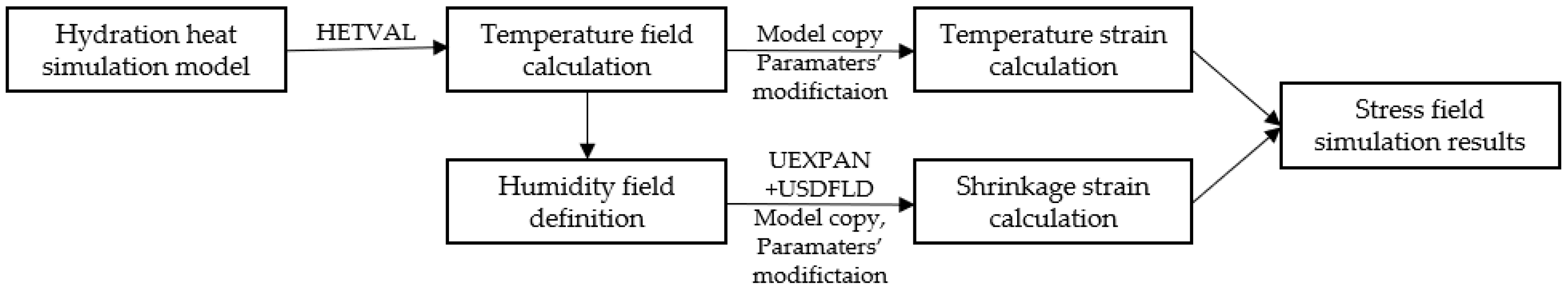
3.3. ABAQUS
- —concrete shrinkage strain during the humidity saturation period;
- —concrete shrinkage strain during the humidity decline period;
- —elastic modulus of concrete;
- —chemical shrinkage at the starting moment;
- —chemical shrinkage at any moment;
- —saturation fraction;
- —universal gas constant;
- —molar weight of water;
- —absolute temperature;
- —bulk modulus of the concrete;
- —bulk modulus of the aggregate;
3.4. ANSYS
3.5. B4Cast
3.6. ATENA
3.7. JCMAC
- —vapor pressure within the concrete;
- —moisture density;
- —moisture capacity;
- —diffusion coefficient;
- —moisture density loss by hydration.
4. Conclusions
Author Contributions
Funding
Data Availability Statement
Acknowledgments
Conflicts of Interest
References
- Klemczak, B.; Gołaszewski, J.; Cygan, G.; Smolana, A.; Gołaszewska, M. Shrinkage Strains Development in Ultralight Cementitious Foams with Embedded MPCM. Dev. Built Environ. 2024, 17, 100299. [Google Scholar] [CrossRef]
- Caggiano, A.; Mankel, C.; Koenders, E. Reviewing Theoretical and Numerical Models for PCM-Embedded Cementitious Composites. Buildings 2019, 9, 3. [Google Scholar] [CrossRef]
- Mastori, H.; Piluso, P.; Haquet, J.-F.; Denoyel, R.; Antoni, M. Limestone-Siliceous and Siliceous Concretes Thermal Damaging at High Temperature. Constr. Build. Mater. 2019, 228, 116671. [Google Scholar] [CrossRef]
- Li, K.-Q.; Li, D.-Q.; Liu, Y. Meso-Scale Investigations on the Effective Thermal Conductivity of Multi-Phase Materials Using the Finite Element Method. Int. J. Heat Mass Transf. 2020, 151, 119383. [Google Scholar] [CrossRef]
- Li, Y.; Fang, J.; Cheng, L.; He, X.; Su, Y.; Tan, H. Mechanical Performance, Hydration Characteristics and Microstructures of High Volume Blast Furnace Ferronickel Slag Cement Mortar by Wet Grinding Activation. Constr. Build. Mater. 2022, 320, 126148. [Google Scholar] [CrossRef]
- ACI Committee. ACI 207.1R-05—Guide to Mass Concrete; American Concrete Institute: Farmington Hills, MI, USA, 2005; p. 30. [Google Scholar]
- Godart, B.; Divet, L. Recommandations for Preventing Disorders Due to Delayed Ettringite Formation: Technical Guide; ResearchGate: Berlin, Germany, 2018. [Google Scholar]
- Bamforth, P.B. Construction Industry Research and Information Association. In Control of Cracking Caused by Restrained Deformation in Concrete; CIRIA C766; CIRIA: London, UK, 2018. [Google Scholar]
- ACI Committee. ACI 116R-00—Cement and Concrete Terminology; American Concrete Institute: Farmington Hills, MI, USA, 2005; p. 73. [Google Scholar]
- Kanavaris, F.; Jędrzejewska, A.; Sfikas, I.P.; Schlicke, D.; Kuperman, S.; Šmilauer, V.; Honório, T.; Fairbairn, E.M.R.; Valentim, G.; Funchal de Faria, E.; et al. Enhanced Massivity Index Based on Evidence from Case Studies: Towards a Robust Pre-Design Assessment of Early-Age Thermal Cracking Risk and Practical Recommendations. Constr. Build. Mater. 2020, 271, 121570. [Google Scholar] [CrossRef]
- Jędrzejewska, A.; Kanavaris, F.; Zych, M.; Schlicke, D.; Azenha, M. Experiences on Early Age Cracking of Wall-on-Slab Concrete Structures. Structures 2020, 27, 2520–2549. [Google Scholar] [CrossRef]
- Zhang, J.; Yu, M.; Chu, X.; Li, R. A Coupled Hygro-Thermo-Mechanical Cosserat Peridynamic Modelling of Fire-Induced Concrete Fracture. Acta Mech. 2024. [Google Scholar] [CrossRef]
- Mansour, D.M.; Ebid, A.M. Modeling of Heat Transfer in Massive Concrete Foundations Using 3D-FDM. Civ. Eng. J. 2023, 9, 2430–2444. [Google Scholar] [CrossRef]
- Ebid, A.M.; Onyelowe, K.C.; Kontoni, D.-P.N.; Gallardo, A.Q.; Hanandeh, S. Heat and Mass Transfer in Different Concrete Structures: A Study of Self-Compacting Concrete and Geopolymer Concrete. Int. J. Low-Carbon Technol. 2023, 18, 404–411. [Google Scholar] [CrossRef]
- Luikov, A.V. Heat and Mass Transfer in Capillary-Porous Bodies. In Advances in Heat Transfer; Irvine, T.F., Hartnett, J.P., Eds.; Elsevier: Amsterdam, The Netherlands, 1964; Volume 1, pp. 123–184. [Google Scholar]
- Luikov, A.V. Systems of Differential Equations of Heat and Mass Transfer in Capillary-Porous Bodies (Review). Int. J. Heat Mass Transf. 1975, 18, 1–14. [Google Scholar] [CrossRef]
- Harmathy, T.Z. Moisture and Heat Transport With Particular Reference to Concrete. In Proceedings of the Environmental Effects on Concrete, Highway Research Board, Washington, DC, USA, 12–16 January 1970; pp. 5–16. [Google Scholar]
- De Vries, D.A. Simultaneous Transfer of Heat and Moisture in Porous Media. Eos Trans. Am. Geophys. Union 1958, 39, 909–916. [Google Scholar] [CrossRef]
- Bažant, Z.P.; Thonguthai, W. Pore Pressure and Drying of Concrete at High Temperature. J. Eng. Mech. Div. 1978, 104, 1059–1079. [Google Scholar] [CrossRef]
- Gawin, D.; Pesavento, F.; Schrefler, B.A. Modelling of Hygro-Thermal Behaviour of Concrete at High Temperature with Thermo-Chemical and Mechanical Material Degradation. Comput. Methods Appl. Mech. Eng. 2003, 192, 1731–1771. [Google Scholar] [CrossRef]
- Lien, H.-P.; Wittmann, F.H. Coupled Heat and Mass Transfer in Concrete Elements at Elevated Temperatures. Nucl. Eng. Des. 1995, 156, 109–119. [Google Scholar] [CrossRef]
- Davie, C.T.; Pearce, C.J.; Bićanić, N. Coupled Heat and Moisture Transport in Concrete at Elevated Temperatures—Effects of Capillary Pressure and Adsorbed Water. Numer. Heat Transf. Part A Appl. 2006, 49, 733–763. [Google Scholar] [CrossRef]
- Ožbolt, J.; Periški, G.; Reinhardt, H.W. 3D Thermo-Hygro-Mechanical Model for Concrete. In Proceedings of the FraMCoS-6, Catania, Italy, 17–22 June 2007; Taylor & Francis: Abingdon, UK, 2007; pp. 533–539. [Google Scholar]
- Bary, B.; Ranc, G.; Durand, S.; Carpentier, O. A Coupled Thermo-Hydro-Mechanical-Damage Model for Concrete Subjected to Moderate Temperatures. Int. J. Heat Mass Transf. 2008, 51, 2847–2862. [Google Scholar] [CrossRef]
- Burkan Isgor, O.; Razaqpur, A.G. Finite Element Modeling of Coupled Heat Transfer, Moisture Transport and Carbonation Processes in Concrete Structures. Cem. Concr. Compos. 2004, 26, 57–73. [Google Scholar] [CrossRef]
- Kwak, H.-G.; Ha, S.-J.; Kim, J.-K. Non-Structural Cracking in RC Walls: Part I. Finite Element Formulation. Cem. Concr. Res. 2006, 36, 749–760. [Google Scholar] [CrossRef]
- Di Luzio, G.; Cusatis, G. Hygro-Thermo-Chemical Modeling of High Performance Concrete. I: Theory. Cem. Concr. Compos. 2009, 31, 301–308. [Google Scholar] [CrossRef]
- Di Luzio, G.; Cusatis, G. Hygro-Thermo-Chemical Modeling of High-Performance Concrete. II: Numerical Implementation, Calibration, and Validation. Cem. Concr. Compos. 2009, 31, 309–324. [Google Scholar] [CrossRef]
- Aurich, M.; Campos Filho, A.; Bittencourt, T.N.; Shah, S.P. Finite Element Modeling of Concrete Behavior at Early Age. Rev. IBRACON Estrut. Mater. 2009, 2, 37–58. [Google Scholar] [CrossRef]
- Gawin, D. A Numerical Solution of Coupled Heat and Moisture Transfer Problems with Phase Changes in Porous Building Materials. Arch. Civ. Eng. 1993, 39, 393–412. [Google Scholar]
- Gawin, D.; Pesavento, F.; Schrefler, B.A. Hygro-Thermo-Chemo-Mechanical Modelling of Concrete at Early Ages and beyond. Part I: Hydration and Hygro-Thermal Phenomena. Int. J. Numer. Methods Eng. 2006, 67, 299–331. [Google Scholar] [CrossRef]
- de Araújo, J.; Awruch, A.M. Cracking Safety Evaluation on Gravity Concrete Dams during the Construction Phase. Comput. Struct. 1998, 66, 93–104. [Google Scholar] [CrossRef]
- Zreiki, J.; Bouchelaghem, F.; Chaouche, M. Early-Age Behaviour of Concrete in Massive Structures, Experimentation and Modelling. Nucl. Eng. Des. 2010, 240, 2643–2654. [Google Scholar] [CrossRef]
- Chen, B.; Tang, G.; Lu, X.; Xiong, B.; Guan, B.; Tian, B. Thermal Property Evolution and Prediction Model of Early-Age Low-Heat Cement Concrete under Different Curing Temperatures. J. Build. Eng. 2024, 82, 108020. [Google Scholar] [CrossRef]
- Mirković, U.; Kuzmanović, V.; Todorović, G. Influence of Monolith Length on Temperature Field of Concrete Gravity Dams. Appl. Sci. 2024, 14, 3248. [Google Scholar] [CrossRef]
- Sumarno, A.; Prasetyo, A.M.; Sari, D.P.; Maidina; Ngeljaratan, L. Thermal Analysis and Solution of Green Cementitious Composites Model under Constant and Elevated Temperature-a Preliminary Study. AIP Conf. Proc. 2024, 2973, 060002. [Google Scholar] [CrossRef]
- Zhang, S.; Liu, P.; Liu, L.; Huang, J.; Cheng, X.; Chen, Y.; Chen, L.; He, S.; Zhang, N.; Yu, Z. Heat of Hydration Analysis and Temperature Field Distribution Study for Super-Long Mass Concrete. Coatings 2024, 14, 369. [Google Scholar] [CrossRef]
- Yu, H.; Wang, F.; Mao, D.; Chen, J.; Xiong, X.; Song, R.; Liu, J. Temperature Monitoring and Simulation Analysis of the Bottom Orifices of Baihetan Arch Dam When Outflowing. Int. Commun. Heat Mass Transf. 2024, 150, 107200. [Google Scholar] [CrossRef]
- Van Tran, M.; Chau, V.N.; Nguyen, P.H. Prediction and Control of Temperature Rise of Massive Reinforced Concrete Transfer Slab with Embedded Cooling Pipe. Case Stud. Constr. Mater. 2023, 18, e01817. [Google Scholar] [CrossRef]
- Cai, Y.; Wang, F.; Zhao, Z.; Lyu, Z.; Wang, Y.; Zou, P. Early-Hydration Heat and Influencing Factor Analysis of Large-Volume Concrete Box Girder Based on Equivalent Age. Structures 2023, 50, 1699–1713. [Google Scholar] [CrossRef]
- Lajimi, N.; Ben Taher, N.; Boukadida, N. Numerical Simulation of Heat and Mass Transfer of a Wall Containing Micro-Encapsulated Phase Change Concrete (PCC). Front. Environ. Sci. 2023, 10, 973725. [Google Scholar] [CrossRef]
- Wasik, M.; Dereszewski, A.; Łapka, P. Prototype of an Experimental Stand for Investigating Heat and Moisture Transfer Phenomena in Building Materials. J. Phys. Conf. Ser. 2023, 2423, 012010. [Google Scholar] [CrossRef]
- Zhu, J.; Wang, Y.; Xiao, R.; Yang, J. Multiscale Theoretical Model of Thermal Conductivity of Concrete and the Mesoscale Simulation of Its Temperature Field. J. Mater. Civ. Eng. 2023, 35, 04022359. [Google Scholar] [CrossRef]
- Prskalo, S.; Gfrerer, M.H.; Schanz, M. Multiphasic Model of Early Stage Hydration in Concrete Using the Theory of Porous Media. Proc. Appl. Math. Mech. 2023, 23, e202300220. [Google Scholar] [CrossRef]
- Yin, H.; Cibelli, A.; Brown, S.-A.; Yang, L.; Shen, L.; Alnaggar, M.; Cusatis, G.; Di Luzio, G. Flow Lattice Model for the Simulation of Chemistry Dependent Transport Phenomena in Cementitious Materials. Eur. J. Environ. Civ. Eng. 2023, 28, 1039–1063. [Google Scholar] [CrossRef]
- Rossat, D.; Baroth, J.; Briffaut, M.; Dufour, F.; Monteil, A.; Masson, B.; Michel-Ponnelle, S. Bayesian Inference with Correction of Model Bias for Thermo-Hydro-Mechanical Models of Large Concrete Structures. Eng. Struct. 2023, 278, 115433. [Google Scholar] [CrossRef]
- Lyu, C.; Xu, M.; Lu, X.; Tian, B.; Chen, B.; Xiong, B.; Cheng, B. Research on Thermal- Humidity -Force Coupling Characteristics of Mass Concrete Structures under Temperature Control. Constr. Build. Mater. 2023, 398, 132540. [Google Scholar] [CrossRef]
- Li, X.; Yu, Z.; Chen, K.; Deng, C.; Yu, F. Investigation of Temperature Development and Cracking Control Strategies of Mass Concrete: A Field Monitoring Case Study. Case Stud. Constr. Mater. 2023, 18, e02144. [Google Scholar] [CrossRef]
- Meghwar, S.L.; Pilakoutas, K.; Torelli, G.; Guadagnini, M. Numerical Determination of Moisture Diffusivity in Concrete. KSCE J. Civ. Eng. 2022, 26, 3932–3944. [Google Scholar] [CrossRef]
- Alper Yikici, T.; Sezer, H.; Chen, H.-L. Modeling Thermal Behavior of Mass Concrete Structures at Early Age. Transp. Res. Rec. 2022, 2676, 536–548. [Google Scholar] [CrossRef]
- Cheng, P.; Zhu, H.; Zhang, Y.; Jiao, Y.; Fish, J. Coupled Thermo-Hydro-Mechanical-Phase Field Modeling for Fire-Induced Spalling in Concrete. Comput. Methods Appl. Mech. Eng. 2022, 389, 114327. [Google Scholar] [CrossRef]
- Bondareva, N.S.; Sheremet, M.A. Heat Transfer Performance in a Concrete Block Containing a Phase Change Material for Thermal Comfort in Buildings. Energy Build. 2022, 256, 111715. [Google Scholar] [CrossRef]
- Mostafavi, S.A.; Joneidi, Z. Thermal Model of Precast Concrete Curing Process: Minimizing Energy Consumption. Math. Comput. Simul. 2022, 191, 82–94. [Google Scholar] [CrossRef]
- Zhang, Z.; Angst, U.M. Effects of Model Boundary Conditions on Simulated Drying Kinetics and Inversely Determined Liquid Water Permeability for Cement-Based Materials. Dry. Technol. 2022, 40, 2741–2758. [Google Scholar] [CrossRef]
- Smolana, A.; Klemczak, B.; Azenha, M.; Schlicke, D. Thermo-Mechanical Analysis of Mass Concrete Foundation Slabs at Early Age—Essential Aspects and Experiences from the FE Modelling. Materials 2022, 15, 1815. [Google Scholar] [CrossRef] [PubMed]
- Kuryłowicz-Cudowska, A.; Wilde, K. FEM and Experimental Investigations of Concrete Temperature Field in the Massive Stemwall of the Bridge Abutment. Constr. Build. Mater. 2022, 347, 128565. [Google Scholar] [CrossRef]
- Chiniforush, A.A.; Gharehchaei, M.; Akbar Nezhad, A.; Castel, A.; Moghaddam, F.; Keyte, L.; Hocking, D.; Foster, S. Minimising Risk of Early-Age Thermal Cracking and Delayed Ettringite Formation in Concrete—A Hybrid Numerical Simulation and Genetic Algorithm Mix Optimisation Approach. Constr. Build. Mater. 2021, 299, 124280. [Google Scholar] [CrossRef]
- You, W.; Liu, X.; Shang, H.; Yang, G. Evolution of Temperature, Humidity and Deformation in Early-Age Cement-Based Materials Based on a Multi-Field Model. Constr. Build. Mater. 2021, 290, 123277. [Google Scholar] [CrossRef]
- Azenha, M.; Kanavaris, F.; Schlicke, D.; Jędrzejewska, A.; Benboudjema, F.; Honorio, T.; Šmilauer, V.; Serra, C.; Forth, J.; Riding, K.; et al. Recommendations of RILEM TC 287-CCS: Thermo-Chemo-Mechanical Modelling of Massive Concrete Structures towards Cracking Risk Assessment. Mater. Struct. 2021, 54, 135. [Google Scholar] [CrossRef]
- Pohl, C.; Šmilauer, V.; Unger, J.F. A Three-Phase Transport Model for High-Temperature Concrete Simulations Validated with X-Ray CT Data. Materials 2021, 14, 5047. [Google Scholar] [CrossRef] [PubMed]
- Zhang, Z.; Liu, Y.; Liu, J.; Zhang, N. Thermo-Mechanical Behavior Simulation and Cracking Risk Evaluation on Steel-Concrete Composite Girders during Hydration Process. Structures 2021, 33, 3912–3928. [Google Scholar] [CrossRef]
- Kanavaris, F.; Ferreira, C.; Sousa, C.; Azenha, M. Thermo-Chemo-Hygro-Mechanical Simulation of the Restrained Shrinkage Ring Test for Cement-Based Materials under Distinct Drying Conditions. Constr. Build. Mater. 2021, 294, 123600. [Google Scholar] [CrossRef]
- Gawin, D.; Pesavento, F.; Schrefler, B.A. Hygro-Thermo-Chemo-Mechanical Modelling of Concrete at Early Ages and beyond. Part II: Shrinkage and Creep of Concrete. Int. J. Numer. Meth. Engng 2006, 67, 332–363. [Google Scholar] [CrossRef]
- Wang, Q.; Ren, X.; Ballarini, R. A Multifield Model for Early-Age Massive Concrete Structures: Hydration, Damage, and Creep. J. Eng. Mech. 2020, 146, 04020115. [Google Scholar] [CrossRef]
- De Schutter, G.; Vuylsteke, M. Minimisation of Early Age Thermal Cracking in a J-Shaped Non-Reinforced Massive Concrete Quay Wall. Eng. Struct. 2004, 26, 801–808. [Google Scholar] [CrossRef]
- Faria, R.; Azenha, M.; Figueiras, J.A. Modelling of Concrete at Early Ages: Application to an Externally Restrained Slab. Cem. Concr. Compos. 2006, 28, 572–585. [Google Scholar] [CrossRef]
- Benboudjema, F.; Torrenti, J.M. Early-Age Behaviour of Concrete Nuclear Containments. Nucl. Eng. Des. 2008, 238, 2495–2506. [Google Scholar] [CrossRef]
- Buffo-Lacarrière, L.; Sellier, A.; Kolani, B. Application of Thermo-Hydro-Chemo-Mechanical Model for Early Age Behaviour of Concrete to Experimental Massive Reinforced Structures with Strain–Restraining System. Eur. J. Environ. Civ. Eng. 2014, 18, 814–827. [Google Scholar] [CrossRef]
- Klemczak, B.; Knoppik-Wróbel, A. Reinforced Concrete Tank Walls and Bridge Abutments: Early-Age Behaviour, Analytic Approaches and Numerical Models. Eng. Struct. 2015, 84, 233–251. [Google Scholar] [CrossRef]
- Bouhjiti, D.E.-M.; Boucher, M.; Briffaut, M.; Dufour, F.; Baroth, J.; Masson, B. Accounting for Realistic Thermo-Hydro-Mechanical Boundary Conditions Whilst Modeling the Ageing of Concrete in Nuclear Containment Buildings: Model Validation and Sensitivity Analysis. Eng. Struct. 2018, 166, 314–338. [Google Scholar] [CrossRef]
- Li, S.; Yang, Y.; Pu, Q.; Wen, W.; Yan, A. Thermo-Hydro-Mechanical Combined Effect Analysis Model for Early-Age Concrete Bridges and Its Application. Adv. Civ. Eng. 2020, 2020, e8864109. [Google Scholar] [CrossRef]
- Zhao, H.; Jiang, K.; Yang, R.; Tang, Y.; Liu, J. Experimental and Theoretical Analysis on Coupled Effect of Hydration, Temperature and Humidity in Early-Age Cement-Based Materials. Int. J. Heat Mass Transf. 2020, 146, 118784. [Google Scholar] [CrossRef]
- Pomaro, B.; Xotta, G.; Salomoni, V.A.; Majorana, C.E. A Thermo-Hydro-Mechanical Numerical Model for Plain Irradiated Concrete in Nuclear Shielding. Mater. Struct. 2022, 55, 14. [Google Scholar] [CrossRef]
- Fourier, J. Theorie Analytique de La Chaleur; CambridgeCore: Paris, France, 1822. [Google Scholar]
- Fick, A. Ueber Diffusion. Ann. Phys. 1855, 170, 59–86. [Google Scholar] [CrossRef]
- Hirschfeld, K. Die Temperaturverteilung im Beton, 1948th ed.; Springer: Berlin/Heidelberg, Germany, 1948; ISBN 978-3-642-49440-6. [Google Scholar]
- Andreasik, M. Napężenia Termiczno–Skurczowe w Masywach Betonowych. Ph.D. Thesis, Cracow University of Technology, Cracow, Poland, 1982. [Google Scholar]
- Černy, R.; Rovnanikova, P. Transport Processes in Concrete; CRC Press: London, UK, 2014; ISBN 978-0-429-18204-4. [Google Scholar]
- Klemczak, B. Prediction of Coupled Heat and Moisture Transfer in Early-Age Massive Concrete Structures. Numer. Heat Transf. Part A Appl. 2011, 60, 212–233. [Google Scholar] [CrossRef]
- Neville, A.M. Properties of Concrete, 5th ed.; Pearson: Longman, UK, 2011; ISBN 978-0-273-75580-7. [Google Scholar]
- van Breugel, I.K. Artificial Cooling of Hardening Concrete; Delft University of Technology: Delft, The Netherlands, 1980. [Google Scholar]
- Tatro, S.B. Thermal Properties. In Significance of Tests and Properties of Concrete and Concrete-Making Materials; ASTM International: West Conshohocken, PA, USA, 2006. [Google Scholar]
- Hancox, N.L. The Diffusion of Water in Concrete; UKAEA: Winfrith, UK, 1966. [Google Scholar]
- Bažant, Z.P.; Najjar, L.J. Nonlinear Water Diffusion in Nonsaturated Concrete. Mater. Constr. 1972, 5, 3–20. [Google Scholar] [CrossRef]
- Wyrwał, J.; Szczęsny, J. Migracja Wilgoci Wywołana Gradientami Temperatury w Płytach Betonowych Poddanych Obróbce Termicznej. Arch. Civ. Eng. 1989, 35, 421–432. [Google Scholar]
- Rastrup, E. Heat of Hydration in Concrete. Mag. Concr. Res. 1954, 6, 79–92. [Google Scholar] [CrossRef]
- Hansen, P.F.; Pedersen, E.J. Maturity Computer for Controlled Curing and Hardening of Concrete; Nordiska Betongfoerbundet: Stockholm, Sweden, 1977. [Google Scholar]
- Bogue, R.H. The Chemistry of Portland Cement; Reinhold Publishing Corporation: New York, NY, USA, 1955; ISBN 978-0-598-89711-4. [Google Scholar]
- Schindler, A.K.; Folliard, K.J. Heat of Hydration Models for Cementitious Materials. ACI Mater. J. 2005, 102, 24–33. [Google Scholar] [CrossRef] [PubMed]
- Ulm, F.-J.; Coussy, O. Couplings in Early-Age Concrete: From Material Modeling to Structural Design. Int. J. Solids Struct. 1998, 35, 4295–4311. [Google Scholar] [CrossRef]
- Cervera, M.; Oliver, J.; Prato, T. Thermo-Chemo-Mechanical Model for Concrete. I: Hydration and Aging. J. Eng. Mech. 1999, 125, 1018–1027. [Google Scholar] [CrossRef]
- Kang, S.-T.; Kim, J.-S.; Lee, Y.; Park, Y.-D.; Kim, J.-K. Moisture Diffusivity of Early Age Concrete Considering Temperature and Porosity. KSCE J. Civ. Eng. 2012, 16, 179–188. [Google Scholar] [CrossRef]
- Azenha, M.; Sousa, C.; Faria, R.; Neves, A. Thermo–Hygro–Mechanical Modelling of Self-Induced Stresses during the Service Life of RC Structures. Eng. Struct. 2011, 33, 3442–3453. [Google Scholar] [CrossRef]
- Wang, C.; Dilger, W.H. Prediction of Temperature Distribution in Hardening Concrete. In Proceedings of the International RILEM Conference on Thermal Cracking in Concrete at Early Ages, London, UK, 10–12 October 1994; pp. 21–28. [Google Scholar]
- Honorio, T.; Bary, B.; Benboudjema, F. Evaluation of the Contribution of Boundary and Initial Conditions in the Chemo-Thermal Analysis of a Massive Concrete Structure. Eng. Struct. 2014, 80, 173–188. [Google Scholar] [CrossRef]
- Gawin, D.; Majorana, C.E.; Schrefler, B.A. Numerical Analysis of Hygro-Thermal Behaviour and Damage of Concrete at High Temperature. Mech. Cohesive-Frict. Mater. 1999, 4, 37–74. [Google Scholar] [CrossRef]
- Reinhardt, H.; Blaauwendraad, J. Temperature Development in Concrete Structures Taking Account of State Dependent Properties. In Proceedings of the RILEM International Conference on Concrete at Early Ages, Paris, France, 6–8 April 1982; pp. 211–218. [Google Scholar]
- Van Breugel, K. Simulation of Hydration and Formation of Structure in Hardening Cement-Based Materials. Ph.D. Thesis, Delft University of Technology, Delft, The Netherlands, 1991. [Google Scholar]
- De Schutter, G.; Taerwe, L. Specific Heat and Thermal Diffusivity of Hardening Concrete. Mag. Concr. Res. 1995, 47, 203–208. [Google Scholar] [CrossRef]
- Briffaut, M.; Benboudjema, F.; Torrenti, J.-M.; Nahas, G. Effects of Early-Age Thermal Behaviour on Damage Risks in Massive Concrete Structures. Eur. J. Environ. Civ. Eng. 2012, 16, 589–605. [Google Scholar] [CrossRef]
- Jendele, L.; Šmilauer, V.; Červenka, J. Multiscale Hydro-Thermo-Mechanical Model for Early-Age and Mature Concrete Structures. Adv. Eng. Softw. 2014, 72, 134–146. [Google Scholar] [CrossRef]
- Bentz, D.P. Transient Plane Source Measurements of the Thermal Properties of Hydrating Cement Pastes. Mater. Struct. 2007, 40, 1073–1080. [Google Scholar] [CrossRef]
- Bohm, H.; Nogales, S. Mori–Tanaka Models for the Thermal Conductivity of Composites with Interfacial Resistance and Particle Size Distributions. Compos. Sci. Technol. 2008, 68, 1181–1187. [Google Scholar] [CrossRef]
- Branco, F.A.; Mendes, P.; Mirambell, E. Heat of Hydration Effects in Concrete Structures. MJ 1992, 89, 139–145. [Google Scholar] [CrossRef]
- Kim, K.-H.; Jeon, S.-E.; Kim, J.-K.; Yang, S. An Experimental Study on Thermal Conductivity of Concrete. Cem. Concr. Res. 2003, 33, 363–371. [Google Scholar] [CrossRef]
- Jonasson, J.E. Modelling of Temperature, Moisture and Stress in Young Concrete. Ph.D. Thesis, Luleå University of Technology, Luleå, Sweden, 1994. [Google Scholar]
- Liu, X.; Jiang, W.; De Schutter, G.; Yuan, Y.; Su, Q. Early-Age Behaviour of Precast Concrete Immersed Tunnel Based on Degree of Hydration Concept. Struct. Concr. 2014, 15, 66–80. [Google Scholar] [CrossRef]
- Smolana, A.; Klemczak, B.; Azenha, M.; Schlicke, D. Experiences and Analysis of the Construction Process of Mass Foundation Slabs Aimed at Reducing the Risk of Early Age Cracks. J. Build. Eng. 2021, 44, 102947. [Google Scholar] [CrossRef]
- Smolana, A.; Klemczak, B.; Azenha, M.; Schlicke, D. Early Age Cracking Risk in a Massive Concrete Foundation Slab: Comparison of Analytical and Numerical Prediction Models with on-Site Measurements. Constr. Build. Mater. 2021, 301, 124135. [Google Scholar] [CrossRef]
- Ayano, T.; Wittmann, F.H. Drying, Moisture Distribution, and Shrinkage of Cement-Based Materials. Mater. Struct. 2002, 35, 134–140. [Google Scholar] [CrossRef]
- Mensi, R.; Acker, P.; Attolou, A. Séchage du béton: Analyse et modélisation. Mater. Struct. 1988, 21, 3–12. [Google Scholar] [CrossRef]
- CEB-FIP. Model Code 2010; Ernst&Sohn: Berlin, Germany, 2013. [Google Scholar]
- Abbasnia, R.; Shekarchi, M.; Ahmadi, J. Evaluation of Concrete Drying Shrinkage Related to Moisture Loss. Mater. J. 2013, 110, 269–278. [Google Scholar] [CrossRef]
- Xi, Y.; Bažant, Z.P.; Molina, L.; Jennings, H.M. Moisture Diffusion in Cementitious Materials. Moisture Capacity and Diffusivity. Adv. Cem. Based Mater. 1994, 1, 258–266. [Google Scholar] [CrossRef]
- EN 1992-1-1; European Standard Eurocode 2—Design of Concrete Structures—Part 1-1: General Rules and Rules for Buildings, Bridges and Civil Engineering Structures. CEN: Brussels, Belgium, 2023.
- Nielsen, C.V.; Kaasgaard, M. Activation Energy for the Concrete Maturity Model—Part 1: Compressive Strength Tests at Different Curing Temperatures. Nord. Concr. Res. 2020, 62, 87–106. [Google Scholar] [CrossRef]
- Nielsen, C.V. Activation Energy for the Concrete Maturity Model—Part 2: New Model for Temperature Dependent Ea. Nord. Concr. Res. 2020, 62, 107–124. [Google Scholar] [CrossRef]
- Yuan, Y.; Wan, Z.L. Prediction of Cracking within Early-Age Concrete Due to Thermal, Drying and Creep Behavior. Cem. Concr. Res. 2002, 32, 1053–1059. [Google Scholar] [CrossRef]
- Klemczak, B.; Knoppik-Wróbel, A. Analysis of Early-Age Thermal and Shrinkage Stresses in Reinforced Concrete Walls (with Appendix). SJ 2014, 111, 313–322. [Google Scholar] [CrossRef]
- JCI. Guidelines for Control of Cracking of Mass Concrete 2016; Japan Concrete Institute: Tokyo, Japan, 2017. [Google Scholar]
- Phung, Q.T.; Ferreira, E.; Seetharam, S.; Nguyen, V.T.; Govaerts, J.; Valcke, E. Understanding Hydration Heat of Mortars Containing Supplementary Cementitious Materials with Potential to Immobilize Heavy Metal Containing Waste. Cem. Concr. Compos. 2021, 115, 103859. [Google Scholar] [CrossRef]
- da Silva, W.R.L.; Šmilauer, V. Fuzzy Affinity Hydration Model. J. Intell. Fuzzy Syst. 2015, 28, 127–139. [Google Scholar] [CrossRef]
- Mariak, A.; Chróścielewski, J.; Sabik, A.; Meronk, B.; Wilde, K. Monitoring of Concrete Curing in Extradosed Bridge Supported by Numerical Simulation. Adv. Sci. Technol. Res. J. 2016, 10, 254–262. [Google Scholar] [CrossRef] [PubMed]
- Reddy, D.H.; Ramaswamy, A. Experimental and Numerical Modeling of Creep in Different Types of Concrete. Heliyon 2018, 4, e00698. [Google Scholar] [CrossRef] [PubMed]
- Nguyen, T.C.; Huynh, T.P.; Tang, V.L. Prevention of Crack Formation in Massive Concrete at an Early Age by Cooling Pipe System. Asian J. Civ. Eng. 2019, 20, 1101–1107. [Google Scholar] [CrossRef]
- Tiwari, A.; Deo, S. Pulsatile Flow in a Cylindrical Tube with Porous Walls: Applications to Blood Flow. J. Porous Media 2013, 16, 335–340. [Google Scholar] [CrossRef]
- Mishra, S.C.; Lankadasu, A.; Beronov, K.N. Application of the Lattice Boltzmann Method for Solving the Energy Equation of a 2-D Transient Conduction–Radiation Problem. Int. J. Heat Mass Transf. 2005, 48, 3648–3659. [Google Scholar] [CrossRef]
- Rangel, R.L.; Cornejo, A.; Oñate, E.; Franci, A. Efficient Discrete Element Modeling of Heat Generation and Transfer in Granular Flows: Validation and Application. Powder Technol. 2024, 439, 119719. [Google Scholar] [CrossRef]
- Krzaczek, M.; Nitka, M.; Tejchman, J. A Novel DEM-Based Pore-Scale Thermal-Hydro-Mechanical Model for Fractured Non-Saturated Porous Materials. Acta Geotech. 2023, 18, 2487–2512. [Google Scholar] [CrossRef]
- Zienkiewicz, O.C.; Taylor, R.L. The Finite Element Method: Volume 1: The Basis; 5. Aufl.; Butterworth-Heinemann: Oxford, UK, 2002; ISBN 978-0-7506-5049-6. [Google Scholar]
- Ambethkar, V.; Srivastava, M.K. Numerical Solutions of a Steady 2-D Incompressible Flow in a Rectangular Domain with Wall Slip Boundary Conditions Using the Finite Volume Method. J. Appl. Math. Comput. Mech. 2017, 16, 5–16. [Google Scholar] [CrossRef]
- Červenka, V.; Jendele, L.; Červenka, J. ATENA Program Documentation Part 1—Theory; Cervenka Consulting Ltd.: Prague, Czech Republic, 2011. [Google Scholar]
- Knoppik-Wróbel, A.; Klemczak, B. Degree of Restraint Concept in Analysis of Early-Age Stresses in Concrete Walls. Eng. Struct. 2015, 102, 369–386. [Google Scholar] [CrossRef]
- Azenha, M.; Faria, R.; Figueiras, H. Thermography as a Technique for Monitoring Early Age Temperatures of Hardening Concrete. Constr. Build. Mater. 2011, 25, 4232–4240. [Google Scholar] [CrossRef]
- Bažant, Z.P.; Beweja, S. Creep and Shrinkage Prediction Model for Analysis and Design of Concrete Structures—Model B3. Mater. Struct. 1995, 28, 357–365. [Google Scholar]
- Azenha, M.; Leitão, L.; Granja, J.L.; De Sousa, C.; Faria, R.; Barros, J.A.O. Experimental Validation of a Framework for Hygro-Mechanical Simulation of Self-Induced Stresses in Concrete. Cem. Concr. Compos. 2017, 80, 41–54. [Google Scholar] [CrossRef]
- De Schutter, G. Degree of Hydration Concept for Early Age Concrete Using DIANA. In Proceedings of the Finite Elements in Civil Engineering Applications: Proceedings of the third DIANA World Conference, Tokyo, Japan, 9–11 October 2002; Hendriks, M.A.N., Rots, J.A., Eds.; A.A. Balkema Publishers: Cape Town, South Africa, 2002; pp. 523–526. [Google Scholar]
- De Schutter, G. Degree of Hydration Based Kelvin Model for the Basic Creep of Early Age Concrete. Mater. Struct. 1999, 32, 260–265. [Google Scholar] [CrossRef]
- Lawrence, A. A Finite Element Model for the Prediction of Thermal Stresses in Mass Concrete. Ph.D. Thesis, University of Florida, Gainesville, FL, USA, 2009. [Google Scholar]
- Diaz, F.; Johansson, R. Early-Age Thermal Cracking in Concrete. A FE-Modelling Approach. Master’s Thesis in the Master’s Programme in Structural Engineering and Building Technology. Master’s Thesis, Chalmers University of Technology, Gothenburg, Sweden, 2016. [Google Scholar]
- MIDAS Information Technology Co., Ltd. Midas Civil On-Line Manual—Civil Structure Design System. Available online: https://manual.midasuser.com/EN_Common/Civil/945/index.htm (accessed on 30 March 2024).
- Seo, Y. Heat of Hydration Analysis. Available online: https://www.midasstructure.com/blog/en/blog/heat-of-hydration-analysis (accessed on 19 April 2024).
- Huang, Y.; Liu, G.; Huang, S.; Rao, R.; Hu, C. Experimental and Finite Element Investigations on the Temperature Field of a Massive Bridge Pier Caused by the Hydration Heat of Concrete. Constr. Build. Mater. 2018, 192, 240–252. [Google Scholar] [CrossRef]
- Zuo, Y.; Wu, Y. Measurement and Analysis of Hydration Heat for Long-Span PC Box Girder Bridge. In Proceedings of the 2022 IEEE International Conference on Intelligent Transportation, Big Data & Smart City (ICITBS), Hengyang, China, 26–27 March 2022; pp. 1168–1173. [Google Scholar]
- SIMULIA User Assistance 2024. Available online: https://help.3ds.com/2024/English/DSSIMULIA_Established/SIMACAEANLRefMap/simaanl-c-heattransfer.htm?contextscope=all (accessed on 19 April 2024).
- Piekarska, W.; Kubiak, M.; Saternus, Z. Application of Abaqus to Analysis of the Temperature Field in Elements Heated by Moving Heat Sources. Arch. Foundry Eng. 2010, 10, 177–182. [Google Scholar]
- Krysl, P. Finite Element Modeling with Abaqus and Python for Thermal and Stress Analysis; Pressure Cooker Press: San Diego, CA, USA, 2017. [Google Scholar]
- Sheng, X.; Xiao, S.; Zheng, W.; Sun, H.; Yang, Y.; Ma, K. Experimental and Finite Element Investigations on Hydration Heat and Early Cracks in Massive Concrete Piers. Case Stud. Constr. Mater. 2023, 18, e01926. [Google Scholar] [CrossRef]
- De Amorim Coelho, N.; Pedroso, L.J.; Da Silva Rêgo, J.H.; Nepomuceno, A.A. Use of ANSYS for Thermal Analysis in Mass Concrete. J. Civ. Eng. Archit. 2014, 8, 860–868. [Google Scholar] [CrossRef]
- Mardmomen, S.; Chen, H.-L. Prediction of the Early Age Thermal Behavior of Mass Concrete Containing SCMs Using ANSYS. J. Therm. Anal. Calorim. 2023, 148, 7899–7917. [Google Scholar] [CrossRef]
- Zhang, P.; Xiong, H.; Wang, R. Measurements and Numerical Simulations for Cast Temperature Field and Early-Age Thermal Stress in Zero Blocks of High-Strength Concrete Box Girders. Adv. Mech. Eng. 2022, 14, 168781322210915. [Google Scholar] [CrossRef]
- Hefni Abdel Aziz, Y.; Abdel Zaher, Y. Predicting Thermal Properties and Temperature Rise in Geopolymer Concrete Structures. Ain Shams Eng. J. 2024, 15, 102704. [Google Scholar] [CrossRef]
- Tahersima, M.; Tikalsky, P. Finite Element Modeling of Hydration Heat in a Concrete Slab-on-Grade Floor with Limestone Blended Cement. Constr. Build. Mater. 2017, 154, 44–50. [Google Scholar] [CrossRef]
- Kurian, T. Numerical Analysis of Temperature Distribution across the Cross Section of a Concrete Dam during Early Ages. In Proceedings of the Recent Advances in Structural Engineering, RASE2013, Kochi, India, 13–15 December 2013. [Google Scholar]
- Tasri, A.; Susilawati, A. Effect of Cooling Water Temperature and Space between Cooling Pipes of Post-Cooling System on Temperature and Thermal Stress in Mass Concrete. J. Build. Eng. 2019, 24, 100731. [Google Scholar] [CrossRef]
- Assad, M.; Hawileh, R.A.; Abdalla, J.A.; Abed, F. Heat Transfer Analysis of Reinforced Concrete Walls in ANSYS and ABAQUS: A Comparative Study. In Proceedings of the 2022 IEEE Advances in Science and Engineering Technology International Conferences (ASET), Dubai, United Arab Emirates, 21 February 2022; pp. 1–5. [Google Scholar]
- ConTech Analysis ApS. B4cast Software for Simulation of Temperatures & Stresses in Hardening Concrete, ConTech Analysis ApS: Lillerød, Denmark.
- Kang, Q.; Ding, J.-T.; Bai, Y.; Chen, B. A Simulation Analysis Method for Crack Resistance of Hydraulic Concrete Based on Temperature-Stress Test. Adv. Mater. Res. 2011, 391–392, 100–106. [Google Scholar] [CrossRef]
- Machado, A.M.L.; Babadopulos, L.F.d.A.L.; Cabral, A.E.B. Casting Plan for a Mass Concrete Foundation of a High-Rise Building for Avoiding DEF and Shrinkage Cracking. J. Build. Rehabil. 2023, 8, 49. [Google Scholar] [CrossRef]
- Cervenka, V.; Cervenka, J.; Jendele, L.; Smilauer, V. ATENA Simulation of Crack Propagation in CONCRACK Benchmark. Eur. J. Environ. Civ. Eng. 2014, 18, 828–844. [Google Scholar] [CrossRef]
- Cervenka, J.; Cervenka, V.; Smilauer, V. Modelling of Crack Development in Young Concrete; International Association of Fracture Mechanics forConcrete and Concrete Structures: Toledo, Spain, 2013. [Google Scholar]


| Year | Chosen Studies Related to the Subject of Heat and Mass Transfer in Cement-Based Materials | General Scope of the Article |
|---|---|---|
| 2024 | Chen B. et al. [34] | thermal analysis/thermal property prediction model based on the experiments, hydration kinetics, and composite material equivalence theory |
| Mirković U. et al. [35] | thermal analysis/FEM/Lusas Academic software (Available online: https://www.lusas.com (accessed on 1 March 2022))/validation | |
| Zhang J. et al. [12] | fully coupled hygro-thermo-mechanical model/FEM/validation | |
| Sumarno A. et al. [36] | thermal analysis/2D model | |
| Zhang S. et al. [37] | thermal fields/numerical simulation/ABAQUS 2021/validation | |
| Yu H. et al. [38] | thermal fields/numerical simulation/validation | |
| 2023 | Mansour D. et al. [13] | thermal analysis/3D-finite difference model/MS Excel |
| Van Tran M. et al. [39] | thermal analysis/numerical simulation/Ansys Fluent software/validation | |
| Cai Y. et al. [40] | thermal field/3D-FEM simulation/ABAQUS/validation | |
| Lajimi N. et al. [41] | hygro-thermal analysis/numerical simulation/DIGITAL Visual FORTRAN 95 | |
| Ebid A. M. et al. [14] | State of the art on heat and mass transfer in self-compacting concrete and geopolymer concrete | |
| Wasik M. et al. [42] | the prototype of the experimental stand for heat and moisture transfer investigation in building materials | |
| Zhu J. et al. [43] | temperature field analysis/mesoscale simulation | |
| Prskalo S. et al. [44] | multi-field model/finite element code PANDAS | |
| Yin H. et al. [45] | multi-field model/3D flow lattice model (FLM) | |
| Rossat D. et al. [46] | thermo-hydro-mechanical model/FE simulation/validation | |
| Lyu C. et al. [47] | thermo-hydro-force coupling model/FE simulation/COMSOL Multiphysics/validation | |
| Li X. et al. [48] | thermal analysis/FEM/Midas FEA software/validation | |
| Meghwar S. L. et al. [49] | moisture diffusion/FE simulation/validation | |
| 2022 | Yikici A. et al. [50] | thermal analysis/3D numerical model/finite volume method (FVM)/MATLAB/validation |
| Cheng P. et al. [51] | coupled thermo-hydro-mechanical–phase field/2D numerical simulation/Fortran/The Intel® oneAPI Math Kernel Library PARDISO | |
| Bondareva et al. [52] | mathematical model of the unsteady coupled heat and mass transfer in concrete containing PCM/validation | |
| Mostafavi S.A. et al. [53] | thermal model/MATLAB | |
| Zhang Z. et al. [54] | moisture transport/2D computational fluid dynamics (CFDs) model | |
| Smolana A. et al. [55] | thermo-mechanical analysis/FEM simulation/DIANA FEA 10.2/validation | |
| Kuryłowicz-Cudowska A. et al. [56] | 1D finite difference (FD) method/MATLAB/2D-FEM/GiD software/validation | |
| 2021 | Chiniforush A.A. et al. [57] | coupled 3D thermal–mechanical numerical analysis/MATLAB/COMSOL ABAQUS 6.14 Multiphysics numerical platform/validation |
| You W. et al. [58] | multi-field coupling model/3D-FEM simulation | |
| Azenha M. et al. [59] | recommendations/state of the art regarding modeling the thermo-chemo-mechanical behavior of massive concrete structures | |
| Pohl C. et al. [60] | three-phase transport model/X-ray computer tomography/validation | |
| Zhang Z. et al. [61] | thermo-mechanical analysis/3D-FEM simulation/ABAQUS/validation | |
| Kanavaris F. et al. [62] | thermo-chemo-hygro-mechanical (TCHM) simulation/MATLAB/DIANA FEA |
| Possible Modeling Strategies | Advantages and Scope of Use | Disadvantages and Limitations |
|---|---|---|
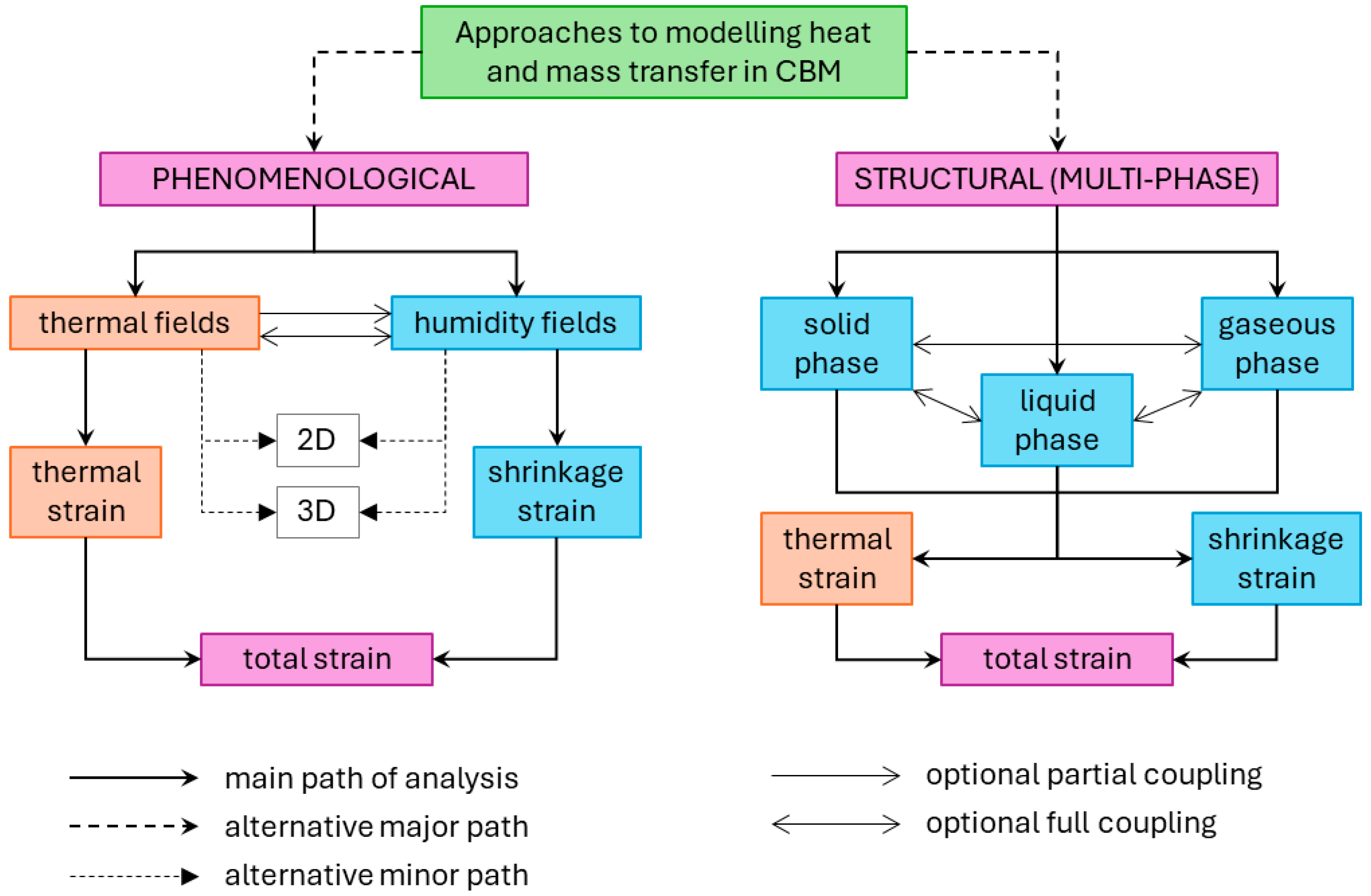
| I. Multi-phase models | Enables accounting for heat and moisture transport intricacies in concrete—a porous medium. Suitable for fundamental research and modeling of laboratory-scale experiments. | Analysis is typically confined to 1-dimensional analysis due to model complexity and numerous associated parameters, necessitating auxiliary testing for determining relevant coefficient values. |
| II. Phenomenological models | Simplifying concrete as a homogeneous solid material facilitates its application in modeling heat and mass transfer for large-scale elements and structures. This approach enables 2- and 3-dimensional analyses with a balanced trade-off between computational effort and result accuracy. | Fails to consider all phenomena associated with the porous nature of concrete, particularly concerning the multidimensionality of the moisture diffusion process. |
| II.1 Thermal analysis only | Suitable for analyzing massive concrete structures where thermal strains induced by hydration heat are predominant, with drying effects being negligible. | Does not accommodate moisture analysis. |
| II.2 Moisture analysis only | Suitable for analyzing thin-walled or small-section elements where drying effects are predominant and hydration heat effects are negligible. | Does not facilitate thermal analysis, including variations in ambient temperature. |
| II.3a Uncoupled thermal and moisture analysis | Suitable for the general-purpose analysis of semi-massive concrete structures, accounting for significant variations in both temperature and moisture. | Does not consider the mutual influence of temperature on moisture diffusion or humidity on temperature transfer in the analyzed element. |
| II.3b Partially coupled thermal and moisture analysis | Typically, the impact of temperature on moisture diffusion is accounted for, enabling a more realistic modeling of moisture transfer within the analyzed element. | The modeling complexity increases due to both the higher number of model parameters and the numerical solution of coupled equations. |
| II.3c Fully coupled thermal and moisture analysis | Enables realistic modeling of both heat and mass transfer in concrete elements. | Among all phenomenological approaches, this method poses the greatest computational challenge due to the multitude of parameters and the numerical solution of interdependent heat and mass transfer equations. |
| Publication [Author, Year] | Major Development/Milestone |
|---|---|
| Fourier, 1822 [74] | Formulation of the law for heat transfer. |
| Fick, 1855 [75] | Formulation of the second law of moisture diffusion. |
| De Vries, 1958 [18] Luikov, 1964 [15] Harmathy, 1970 [17] | Formulation of equations for heat and mass transfer in porous materials. |
| Hirschfeld, 1948 [76] De Vries, 1958 [18] Luikov, 1964 [15] Harmathy, 1970 [17] | Formulation of heat equation with source function from hydration heat for hardening concrete. |
| De Vries, 1958 [18] Luikov, 1964 [15] Harmathy, 1970 [17] | Formulation of the equation for moisture diffusion with sink function due to bounding of water during hydration. |
| Bažant and Thounguthai, 1978 [19] | Partial coupling of heat and moisture diffusion—definition of the moisture diffusion coefficient as dependent on temperature. |
| Andreasik, 1982 [77] | Partial coupling of heat and moisture diffusion—definition of the thermal diffusion coefficient as dependent on humidity. |
| Černy and Rovnanikova, 2002 [78] Klemczak, 2011 [79] | Full coupling of thermal and moisture diffusion equations. |
| Neville, 1963 [80] | Definition of the thermal diffusion coefficient of hardening concrete as dependent on the degree of hydration, moisture content, and temperature. |
| Van Breugel, 1980 [81] | Definition of thermal conductivity of concrete as independent of the temperature for typical temperature ranges during operation. |
| Gawin et al., 2006 [31] | Definition of thermal conductivity of concrete as dependent on the moisture content. |
| Tatro, 2006 [82] | Definition of the specific heat of concrete as dependent on the temperature. |
| Hancox, 1966 [83] Bažant and Najjar, 1972 [84] | Definition of the moisture diffusion coefficient as dependent on the moisture content. |
| Gawin, 1993 [30] | Definition of the coefficient for partial coupling of thermal diffusion with moisture content. |
| Wyrwał and Szczęsny, 1989 [85] | Definition of the coefficient for partial coupling of moisture diffusion with temperature. |
| Faria et al., 2006 [66] | Definition of the combined convection–radiation coefficient of heat exchange. |
| Rastrup, 1954 [86] Hansen and Pedersen, 1977 [87] | Formulation of the equivalent age concept for hardening concrete and Arrhenius-based equation of the equivalent age dependent on the activation energy. |
| Bogue, 1955 [88] | Definition of the formula for calculation of the cumulative hydration heat of Portland cement-based concrete. |
| Schindler and Folliard, 2005 [89] | Definition of the formula for calculation of the cumulative hydration heat of mixed-binder concrete. |
| Ulm and Coussy, 1998 [90] | Definition of the Arrhenius-based affinity law for hardening concrete. |
| Cervera et al., 1999 [91] | Proposals for the normalized affinity function. |
Disclaimer/Publisher’s Note: The statements, opinions and data contained in all publications are solely those of the individual author(s) and contributor(s) and not of MDPI and/or the editor(s). MDPI and/or the editor(s) disclaim responsibility for any injury to people or property resulting from any ideas, methods, instructions or products referred to in the content. |
© 2024 by the authors. Licensee MDPI, Basel, Switzerland. This article is an open access article distributed under the terms and conditions of the Creative Commons Attribution (CC BY) license (https://creativecommons.org/licenses/by/4.0/).
Share and Cite
Klemczak, B.; Smolana, A.; Jędrzejewska, A. Modeling of Heat and Mass Transfer in Cement-Based Materials during Cement Hydration—A Review. Energies 2024, 17, 2513. https://doi.org/10.3390/en17112513
Klemczak B, Smolana A, Jędrzejewska A. Modeling of Heat and Mass Transfer in Cement-Based Materials during Cement Hydration—A Review. Energies. 2024; 17(11):2513. https://doi.org/10.3390/en17112513
Chicago/Turabian StyleKlemczak, Barbara, Aneta Smolana, and Agnieszka Jędrzejewska. 2024. "Modeling of Heat and Mass Transfer in Cement-Based Materials during Cement Hydration—A Review" Energies 17, no. 11: 2513. https://doi.org/10.3390/en17112513
APA StyleKlemczak, B., Smolana, A., & Jędrzejewska, A. (2024). Modeling of Heat and Mass Transfer in Cement-Based Materials during Cement Hydration—A Review. Energies, 17(11), 2513. https://doi.org/10.3390/en17112513