Abstract
The application of a two-phase ejector allows for the mixing of liquid and gas and provides effective heat transfer between phases. The aim of the study is a numerical investigation of the performance of a water-driven, condensing two-phase ejector. The research was performed using CFD methods, which can provide an opportunity to analyze this complex phenomenon in 2D or 3D. The 2D axisymmetric model was developed using CFD software Siemens StarCCM+ 2022.1.1. The Reynolds-Averaged Navier–Stokes (RANS) approach with the Realisable k-ε turbulence model was applied. The multiphase flow was calculated using the mixture model. The boiling/condensation model, where the condensation rate is limited by thermal diffusion, was applied to take into account direct contact condensation. Based on the mass balance calculations and developed pressure and steam volume fraction distributions, the ejector performance was analyzed for various boundary conditions. The influence of the suction pressure (range between 0.812 and 0.90) and the steam mass flow rate (range between 10 g/s and 25 g/s) is presented to investigate the steam condensation phenomenon inside the ejector condenser. The provided mixture of inert gas (CO2) with steam (H2O) in the ejector condenser was investigated also. The weakening of the steam condensation process by adding CO2 gas was observed, but it is still possible to achieve effective condensation despite the presence of inert gas.
1. Introduction
Constantly growing energy consumption forces scientists to look for alternative ways of increasing energy efficiency. Because of their simplicity of construction, reliable operation, and low investment cost, ejectors are being increasingly applied in many industries: power, refrigeration, and ventilation systems. They are taking the role of pumps, compressors, and mixers. The technology of ejectors has been known for at least a century []. There is no uniform way of ejector classification. Sokolov and Zinger [] propose a division taking into account modelling difficulty, where the third category is the most challenging []:
- -
- Ejector operating with primary and secondary fluid in the same phase.
- -
- Ejector operating with primary and secondary fluid in various phases, but phase change does not occur.
- -
- Ejector operating with primary and secondary fluid in various phases, and phase change phenomenon occurs.
The last category is called a two-phase ejector with phase change, and due to the complexity of the multiphase flow, including interfacial interactions, it is still not fully understood [].
There are two approaches in ejector modelling: 0D/1D models [,,] and CFD (Computational Fluid Dynamics) models. The first sets of dimensions are usually calculated using 0D/1D models. These models are based on significant simplification, for example, ideal gas with constant properties, steady-state conditions, isentropic flow, adiabatic processes on the wall, and constant pressure and constant area assumptions. CFD methods allow for most of the limitations of 0D/1D models to be overcome. They are especially good for complex phenomena like multiphase flow with interphase interactions [,]. Moreover, CFD methods allow for the simulation of a wide range of flow patterns like gas–liquid slag flow [,]. Considering two-phase ejector phenomena, complex processes occur inside the mixing chamber and diffuser part i where non-equilibrium processes are the most significant. CFD allows for a qualitative assessment of the phenomenon, which allows for a deeper understanding of it. The disadvantage of CFD calculations compared to 0D/1D models is the greater demand for computing power and time consumption, but due to the growing possibilities of computer power, it becomes less and less significant. Taking into account all the strengths of the CFD methods, this approach seems to be a promising method for calculating the phenomenon inside the two-phase ejector with the phase change (condensation).
Considering the CFD approach, the following challenges are related to the modelling of a two-phase ejector: turbulence, multiphase, and phase change. The turbulence model plays a crucial role in forecasting ejector efficiency []. In the modeling of two-phase flow in the ejector, mainly two, two-equation RANS-based turbulence models in various modifications are considered: k-ε and k-ω models. Li et al. [] compared three turbulence models: in gas–liquid ejector in two-phase mode against experimental data. The entrainment ratio was overpredicted in the case of the k-ω SST model for small differences between the pressure at the gas inlet and ejector outlet. Smołka et al. [] used a k-ε RNG together with HEM to simulate compressible, high-speed flow in the two-phase ejector. A realizable k-ε turbulence model was used by Haida et al. [] in the developed CO2 two-phase ejector model. Palacz et al. [] developed a 3D CFD model of a two-phase CO2 ejector using a realistic k-ε turbulence model with a HEM (Homogeneous Equilibrium Model) approach to analyze the accuracy of the model. The error of motive and suction nozzles mass flow rates were less than 10%. Other numerical investigations of ejectors show that the k-ε models are appropriate for ejector calculation because of their robustness and accuracy [,,].
Multiphase modelling in the two-phase ejector is mainly based on the Euler–Euler approach because it provides a balance between accuracy, computational efficiency, and versatility. The most commonly used are the Eulerian two-fluid and simplified mixture model, which treats phases as one phase with averaged properties of the mixture; therefore, it is named also as a single (pseudo) fluid approach. A mixture model was used by Zheng et al. [] to model a two-phase flow with phase change in the ejector, where the primary fluid was LNG and the secondary fluid was BOG. Gaciomelli et al. [] applied the HEM and Mixture models to calculate the flash flow in the two-phase ejector, and the mixture model better predicted mass flow rates and pressure profiles. A non-homogeneous mixture model combined with a thermally controlled boiling model and an inertia-controlled cavitation model was used by Yazdani et al. [] to calculate the two-phase flow in the CO2 ejector. The air–water ejector was simulated by Balamurugan et al. [] using the mixture model to develop hydrodynamics characteristics for a wide range of ejector geometry modes. The mixture model was used by Yuan et al. [] to investigate the influence of several variables on the operation of the water–air ejector. Assari et al. [] applied two different methods for multiphase modeling in a water–air ejector: the mixture and two-phase Eulerian–Eulerian methods. The mixture model was more efficient and more consistent with the experimental data.
Another aspect of multiphase modelling is the phase change process, which considerably influences the performance characteristics and flow patterns. Condensation occurs in equilibrium and high-speed non-equilibrium modes, which often takes place in the supersonic nozzle [,,,]. In gas–liquid ejectors, the jet is highly turbulent and liquid and gas after mixing form a fairly homogeneous mixture with high mass transfer rates [,,,]. Especially challenging is the modelling of direct contact condensation (DCC) []. The most common models are based on thermally driven models, where the transferred mass due to condensation is computed based on the heat balance between the phases and their interfaces [,,,]. To obtain an accurate solution, the two-resistance thermal models require a well-defined interfacial area density (e.g., droplet, bubble diameters), heat transfer coefficient, or/and Nusselt number correlation []. The thermally driven models show good agreement with the experimental data for the condensation of the steam jet [,]. A separate issue that requires thorough analysis is the presence of inert gases and their influence on the effectiveness of the condensation. Based on the results from analytical modelling, Mikielewicz et al. [] showed that the presence of inert gases causes a weaker condensation process. Wang et al. [] conducted an experimental study on the condensation of steam with various mass contents of the air and the results showed that the heat transfer coefficient was decreasing with an increase in the inert gas content. A similar conclusion was proposed by Ma et al. [] who investigated steam condensation in the presence of non-condensable gas in high-pressure conditions.
Currently, the experimental and numerical research about two-phase ejectors concerns mainly their application in refrigeration systems [,,,] where they replace the compressor and work usually in the supersonic mode []. This allows for an increase in the overall efficiency and thus saves energy. There is a lack of investigation of two-phase, liquid-driven ejectors for other applications, especially where the phase change (condensation) takes place as a result of contact between the gas and subcooled liquid in the presence of the inert gas. It causes the phenomena to not be fully understood, and the modeling techniques still require development.
The object of the numerical investigation is a two-phase, water-driven ejector condenser. The ejector is a critical component of the gas power plant with negative CO2 emission []. Applying an ejector condenser in the developed gas power plant can be helpful in reducing pressure at the gas turbine outlet and increasing pressure at the condenser outlet []. Reducing the size and weight of the condenser can be achieved through the use of the Direct Contact Condensation phenomenon instead of contact condensation through the wall surface. In the analyzed case, direct contact condensation occurs due to contact between motive water and steam in the presence of CO2. Because of the complexity of the phenomenon and for a better understanding of crucial processes, both the values at the boundary surfaces and along the flow path could be investigated [,]. The CFD approach based on the FVM (Finite Volume Method) is used to calculate turbulent, multiphase flow with phase change. The 2D axisymmetric model application reduces the computational time, maintaining the high accuracy of the obtained results. The two-equation eddy viscosity, realizable model k-ε, which is based on the Reynolds-Averaged Navier–Stokes (RANS), was used to calculate the turbulent multiphase flow. The DCC phenomenon (Direct Contact Condensation) was calculated using the boiling/condensation model, where the computed value of the transferred mass between water and steam is determined by the heat balance between the phases and their interfaces.
The study aims to investigate the performance of the water-driven two-phase ejector for a developed geometrical model taking into account various inlet gas pressures and the presence of CO2. The analysis was conducted based on balance calculation and flow quantities along the flow path and distributions.
2. Object of the Research
The object of the research is a liquid-driven, subsonic two-phase spray-ejector condenser, presented in Figure 1 (AGH in Kraków) []. Detailed dimensions are presented in Table 1.

Figure 1.
Two-phase ejector condenser.

Table 1.
Main dimensions of the two-phase ejector [].
3. CFD Model of Two-Phase Ejector
3.1. Multiphase Flow Modeling—Mixture Multiphase Model (MMP)
The integral form of the governing equations of the continuity, momentum, energy, and volume fractions of phase i for The mixture multiphase model are presented at steady-state conditions, respectively in Equations (1)–(4).
3.2. Turbulence Modeling—K-Epsilon Model
The transport equations for the realizable k-ε model: the turbulent kinetic energy, k, and the turbulent dissipation rate, ε, are presented (Equations (5) and (6)). The turbulent eddy viscosity was calculated using Equation (7).
3.3. Condensation—Boiling/Condensation Model
In the considered boiling/condensation model, the rate of boiling/condensation between phases i and j depends only on the heat transfer between these phases and can be expressed as
The heat transfer from the interface ij (where boiling/condensation phenomenon occurs) to each of the two phases i and j is described as
For the heat and mass transfer, the interaction area, a, is calculated according to the “spherical particle” interaction area density model, which uses the surface area of spherical particles []. The interaction area density, a, between continuous phase c and a dispersed phase d is calculated as follows:
The calculated heat transfer coefficient, h, depends on the continuous phase heat conductivity, λ, the Nusselt number, Nu (assumed constant value), and the continuous-dispersed interaction length scale, l.
3.4. Geometrical Model and Numerical Mesh
The 2D axisymmetric geometrical model of the two-phase ejector condenser was developed based on the dimensions presented in Table 1. The mesh-independent study presented in Figure 2 was conducted based on the cross-sectional mass-averaged temperature along the flow path for three different meshes with the following number of elements: 14,938, 28,299, and 60,787. There were differences between the temperatures at the beginning, but the achieved mixture temperature in the mixing chamber and at the ejector outlet was the same for all the considered meshes. Taking into account the results from the considered analysis as well as residual values, oscillations, and computational time, the mesh with 28,299 elements was selected. The selected mesh is presented in Figure 3. The base size was 1.25 mm. The inflation layer was applied: three inflation layers with a 1.6 stretching factor.
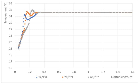
Figure 2.
Mesh independence study based on the cross-sectional mass-averaged temperature along the flow path.

Figure 3.
Selected mesh of the ejector.
3.5. Assumptions and Boundary Conditions
The general scheme of the boundary conditions for the 2D axisymmetric model is presented in Figure 4. Various boundary conditions (mass flow, velocity, pressure) at water and gas inlets were investigated. The detailed values at the boundary surfaces are presented in Table 2. Pressure outlet boundary conditions were applied at the ejector outlet. The impact of the inlet gas pressure and CO2 presence was analyzed to investigate the ejector performance using developed models. Constant properties of steam and CO2 were assumed based on the IAPWS-IF97 [] tables and NIST Chemistry WebBook [], respectively.

Figure 4.
Two-phase ejector condenser boundary faces.

Table 2.
Boundary conditions.
3.6. Numerical Solutions
The segregated flow model, where the conservation equations of mass and momentum are solved in a sequential manner, was applied with SIMPLE pressure–velocity coupling algorithms. The second-order scheme was used in the modelling of convection in all the solvers (turbulence, energy, multiphase). The relaxation factors used in the simulations are presented in Table 3.

Table 3.
Boundary conditions.
4. Results and Discussion
4.1. The Influence of the Suction Pressure on the Ejector Performance
The influence of the suction pressure (0.812, 0.82, 0.84, 0.86, 0.88, 0.90) on the ejector performance is presented in this section. The results for the basic operation mode (0.9 bar) are presented in Table 4. The assumed motive water pressure was 12 bar. The steam was fully condensed (no steam at the outlet). The mass flow rate of the gas at the inlet and the mass-average outlet temperature of the mixture as a function of the suction pressure are presented in Figure 5. A lower sucked-in mass flow rate of gas and a lower outlet temperature can be observed for a lower suction pressure. For a gas inlet pressure equal to 0.813 bar, a 10 g/s gas mass flow rate is achieved. The highest value mass flow rate of 25 g/s was achieved for a gas inlet pressure of 0.9 bar. The outlet temperature varied from 33 °C to 54 °C as a function of the suction pressure.

Table 4.
Results for basic operation mode (assumed suction pressure 0.9 bar).
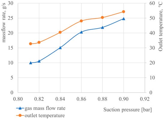
Figure 5.
Gas mass flow rate and mass-averaged outlet mixture temperature as a function of suction pressure (gas inlet pressure).
Steam volume fraction charts along the flow path for various gas inlet pressures are presented in Figure 6. The steam volume fraction decreases along the length of the ejector for all the considered cases. If the inlet gas pressure decreases, the steam volume fraction decreases faster along the length.
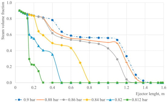
Figure 6.
Steam volume fraction charts along the flow path for various gas inlet pressures.
Figure 7 shows the CO2 distribution for various gas inlet pressures. The CO2 volume fraction contour varies mainly along the flow path. The lower the suction pressure, the more rapid the growth of the CO2 volume content due to a more intensive condensation phenomenon. The highest concentration is about 0.7–0.8, located in the diffuser part.
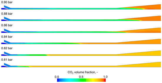
Figure 7.
CO2 distribution for various gas inlet pressures.
The pressure distribution for various gas inlet pressures is presented in Figure 8. The sub-pressure region can be observed at the suction chamber and at the beginning of the mixing chamber. The level of the sub-pressure and its range depend on the assumed gas inlet pressure. The pressure changes along the flow path, but small pressure disturbances in the radial direction are located in the water jet region.
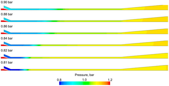
Figure 8.
Pressure distribution for various gas inlet pressures.
Figure 9 presents the velocity scalar field for various gas inlet pressures. The higher the gas inlet pressure, the higher the mixture velocity. The mixture velocity is about 50 m/s at the beginning of the mixing chamber and gradually decreases along the flow path due to the steam volume fraction reduction. The greatest value of the velocity can be observed at the beginning of the mixing chamber, where two streams meet: nearly 100 m/s for the 0.9 bar gas inlet pressure.
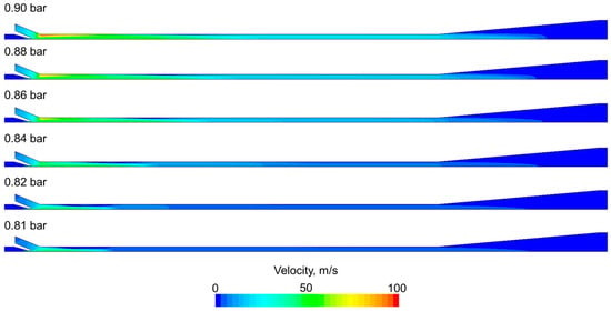
Figure 9.
Velocity distribution for various gas inlet pressures.
The temperature distribution for the fluid mixture is presented in Figure 10. In the beginning, differences occur both in the axial and radial directions. The heat transfer process between the subcooled water and hot gases is very efficient: the temperatures equalize very quickly. The mass-averaged outlet temperature is about 40 °C for a 0.9 bar gas inlet pressure and gradually decreases when the gas inlet pressure decreases. This is due to the fact that less steam is condensed.
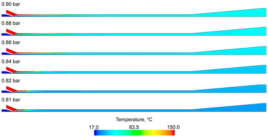
Figure 10.
Temperature distribution for various gas streams.
4.2. The Influence of the CO2 Content on the Ejector Performance
In this section, three cases are considered (10 g steam, 8 g steam, 8 g steam + 2 g CO2). The assumed velocity at the motive water inlet is 0.67 m/s. Cross-sectional average static pressure charts for the considered cases are presented in Figure 11. For the mixture of steam (8 g) and CO2 (2 g), the inlet gas pressure is about 0.8 bar, whereas for the pure steam cases (10 g and 8 g). it is above 0.5 bar. The most significant pressure growth occurs in the first part of the ejector (to 0.3 m of ejector length). Figure 12 shows the pressure distribution for various gas streams. The pressure distributions for the pure steam cases are similar. Moreover, for those cases, the pressure is changing also in the radial direction in the region of the water jet, where fluctuation occurs.
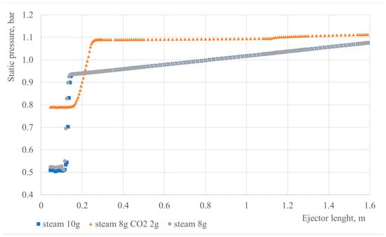
Figure 11.
Steam pressure charts along the flow path for various gas streams.
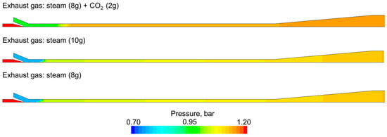
Figure 12.
Pressure distribution for various gas streams.
Considering the velocity distribution presented in Figure 13, a higher mixture velocity is observed for the case with CO2. CO2 is present even after condensation and significantly increases the specific volume of the mixture, which directly influences the mixture velocity. The maximum velocity is about 60 m/s in the water jet region, which is far from the speed sound.
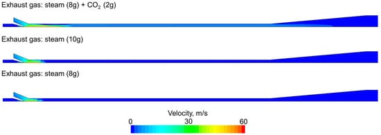
Figure 13.
Velocity distribution for various gas streams.
Figure 14 shows the temperature distribution for the considered various gas streams. The average temperature for the exhaust gas with CO2 is lower than the pure cases, which is caused by the heat capacity of CO2 The temperature is becoming uniform very quickly and does not change along the flow path, which indicates that all the steam is condensed rapidly. This observation is confirmed by Figure 15, which shows the water volume fraction distribution. For the pure steam cases (10 g and 8 g steam), the water fills the entire domain, whereas for the mixture of steam and CO2, the water volume fraction is about 0.2. The steam is fully condensed in all cases; therefore, the difference is due to the presence of CO2, which occupies the domain after condensation.
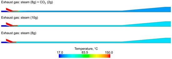
Figure 14.
Temperature distribution for various gas streams.
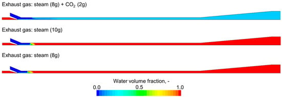
Figure 15.
Water volume fraction distribution for various gas streams.
5. Conclusions
The numerical model of a two-phase ejector considering steam condensation with the presence of CO2 was developed using Siemens Star-CCM+ 2022.1.1. software. The turbulent, multiphase flow was taken into account using the realizable k-ε model and the mixture multiphase model, respectively. The Direct Contact Condensation was computed using a two-resistance, thermally driven boiling/condensation model. In the developed model, CO2 presence in the exhaust gas mixture directly affects the velocity, pressure, temperature, and water volume fraction distribution inside the ejector condenser. The influence of the gas inlet pressure and the CO2 content on the ejector performance was investigated. The conclusions are as follows:
- A correlation exists between the inlet gas pressure and the inlet mass flow rate of the sucked-in gas: the lower the gas inlet pressure, the lower the entrained gas stream. Decreasing the gas inlet pressure causes a reduction in the mixture velocity as well as a reduction in the outlet temperature.
- The presence of CO2 has an impact on the inlet ejector pressure. For the cases with pure steam, the gas inlet pressure is smaller than for the case with the steam and CO2 mixture: 0.5 bar and 0.8 bar, respectively. The reason is the lower (around 2.5 times smaller) specific volume of CO2 (0.798 m3/kg) in comparison with H2O (1.937 m3/kg).
- For all the considered cases, the condensation rate difference is directly connected to the mass flow rate of the sucked-in exhaust gas. For the highest exhaust gas mass flow rate (25 g/s), which corresponds to the inlet pressure (0.9 bar), the steam is fully condensed in the last part of the two-phase ejector (diffuser part).
- Future work connected with the modeling of condensing two-phase ejectors should focus on improving the condensation sub-model and the CO2 presence impact on the condensation phenomenon.
Author Contributions
Conceptualization, T.K. and P.M.; methodology, T.K. and P.M.; software, T.K. and P.M.; validation, P.M.; formal analysis, P.M.; investigation, T.K. and P.M.; resources, T.K. and P.M.; data curation, T.K. and P.M.; writing—original draft preparation, T.K.; writing—review and editing, T.K. and P.M.; visualization, T.K.; supervision, P.M.; project administration, P.M.; funding acquisition, P.M. All authors have read and agreed to the published version of the manuscript.
Funding
The research leading to these results received funding from the Norway Grants 2014–2021 via the National Centre for Research and Development. The work has been prepared within the frame of the project “Negative CO2 Emission Gas Power Plant”—NOR/POLNORCCS/NEGATIVE-CO2-PP/0009/2019-00, which is co-financed by the program “Applied Research” under the Norwegian Financial Mechanisms 2014–2021 POLNOR CCS 2019—Development of CO2 Capture Solutions Integrated in Power and Industry Processes.
Data Availability Statement
Data available on request due to restrictions (e.g., privacy, legal or ethical reasons).
Conflicts of Interest
The authors declare no conflicts of interest. The funders had no role in the design of the study; in the collection, analyses, or interpretation of the data; in the writing of the manuscript; or in the decision to publish the results.
Nomenclature
| surface area vector, m2 | |
| interfacial area per unit volume/interaction area density, 1/m | |
| coefficient | |
| coefficients | |
| body force vector, N/m3 | |
| dumping functions | |
| heat transfer coefficient, W/m2k | |
| phase change heat, J/kg | |
| total enthalpy of the mixture, m2/s2 | |
| unity tensor | |
| turbulent kinetic energy, J/kg | |
| interaction length scale, m | |
| mass rate of boiling/condensation, kg/m3s | |
| Nusselt number | |
| pressure, Pa | |
| turbulent kinetic energy production term, W/m3 | |
| turbulent dissipation rate production term, W/m3 | |
| unity tensor | |
| heat transfer rate, W/m3 | |
| energy source term, W/m3 | |
| turbulent kinetic energy source term, W/m3 | |
| phase source term, 1/s | |
| temperature, K | |
| large eddy time scale, s | |
| specific time scale, s | |
| viscous stress tensor, Pa | |
| turbulent time scale, s | |
| mean velocity, m/s | |
| the mass-averaged velocity, m/s | |
| volume, m3 | |
| volume fraction of phase | |
| turbulent dissipation rate, J/kg s | |
| ambient value of turbulent dissipation rate that counteracts turbulence decay [], J/kg s | |
| conductivity, W/mK | |
| dynamic viscosity, Pa s | |
| turbulent dynamic viscosity, Pa s | |
| density of the mixture, kg/m3 | |
| model coefficients | |
| turbulent Schmidt number |
References
- Goliński, J.; Troskolański, A. Strumienice Teoria i Konstrukcja; WNT: Warszawa, Poland, 1979. [Google Scholar]
- Sokolov, E.; Zinger, N. Jet Devices; Energoatomizdat: Moscow, Russia, 1989. (In Russian) [Google Scholar]
- Grazzini, G.; Milazzo, A.; Mazzelli, F. Ejector for Efficient Refrigeration. Design, Applications and Computational Fluid Dynamics; Springer International Publishing: Cham, Switzerland, 2018. [Google Scholar] [CrossRef]
- Besagni, G. Ejectors on the cutting edge: The past, the present and the perspective. Energy 2019, 170, 998–1003. [Google Scholar] [CrossRef]
- Śmierciew, K.; Butrymowicz, D.; Kwidziński, R.; Przybyliński, T. Analysis of application of two-phase injector in ejector refrigeration systems for isobutane. Appl. Therm. Eng. 2015, 78, 630–639. [Google Scholar] [CrossRef]
- Banasiak, K.; Hafner, A. 1D Computational model of a two-phase R744 ejector for expansion work recovery. Int. J. Therm. Sci. 2011, 50, 2235–2247. [Google Scholar] [CrossRef]
- Angielczyk, W.; Bartosiewicz, Y.; Butrymowicz, D.; Jean-Marie, S. 1-D Modeling of Supersonic Carbon Dioxide Two-Phase Flow Through Ejector Motive Nozzle. In Proceeding of the International Refrigeration and Air Conditioning Conferences, West Lafayette, IN, USA, 12–15 July 2010. Paper 1102. [Google Scholar]
- Liu, Y.; Ozbayoglu, E.M.; Upchurch, E.R.; Baldino, S. Computational fluid dynamics simulations of Taylor bubbles rising in vertical and inclined concentric annuli. Int. J. Multiph. Flow 2023, 159, 104333. [Google Scholar] [CrossRef]
- Liu, Y.; Mitchell, T.; Upchurch, E.R.; Ozbayoglu, E.M.; Baldino, S. Investigation of Taylor bubble dynamics in annular conduits with counter-current flow. Int. J. Multiph. Flow 2024, 170, 104626. [Google Scholar] [CrossRef]
- Yan, Q.; Li, D.; Wang, K.; Zheng, G. Study on the Hydrodynamic Evolution Mechanism and Drift Flow Patterns of Pipeline Gas–Liquid Flow. Processes 2024, 12, 695. [Google Scholar] [CrossRef]
- Zheng, G.; Xu, P.; Li, L.; Fan, X. Investigations of the Formation Mechanism and Pressure Pulsation Characteristics of Pipeline Gas-Liquid Slug Flows. J. Mar. Sci. Eng. 2024, 12, 590. [Google Scholar] [CrossRef]
- Bartosiewicz, Y.; Aidoun, Z.; Mercadier, Y. Numerical assessment of ejector operation for refrigeration applications based on CFD. Appl. Therm. Eng. 2006, 26, 604–612. [Google Scholar] [CrossRef]
- Li, C.; Li, Y.Z. Investigation of entrainment behavior and characteristics of gas-liquid ejectors based on CFD simulation. Chem. Eng. Sci. 2011, 66, 405–416. [Google Scholar] [CrossRef]
- Smolka, J.; Bulinski, Z.; Fic, A.; Nowak, A.J.; Banasiak, K.; Hafner, A. A computational model of a transcritical R744 ejector based on a homogeneous real fluid approach. Appl. Math. Model. 2013, 37, 1208–1224. [Google Scholar] [CrossRef]
- Haida, M.; Smolka, J.; Hafner, A.; Ostrowski, Z.; Palacz, M.; Nowak, A.J.; Banasiak, K. System model derivation of the CO2 two-phase ejector based on the CFD-based reduced-order model. Energy 2018, 144, 941–956. [Google Scholar] [CrossRef]
- Palacz, M.; Smolka, J.; Fic, A.; Bulinski, Z.; Nowak, A.J.; Banasiak, K.; Hafner, A. Application range of the HEM approach for CO2 expansion inside two-phase ejectors for supermarket refrigeration systems. Int. J. Refrig. 2015, 59, 251–258. [Google Scholar] [CrossRef]
- Ringstad, K.E.; Allouche, Y.; Gullo, P.; Ervik, A.; Banasiak, K.; Hafner, A. A Detailed Review on CO2 Two-Phase Ejector Flow Modeling. Therm. Sci. Eng. Prog. 2020, 20, 100647. [Google Scholar] [CrossRef]
- Colarossi, M.; Trask, N.; Schmidt, D.P.; Bergander, M.J. Multidimensional Modeling of Condensing Two-Phase Ejector Flow. Int. J. Refrig. 2012, 35, 290–299. [Google Scholar] [CrossRef]
- Muhammad, H.A.; Abdullah, H.M.; Rehman, Z.; Lee, M.; Baik, Y.-J.; Cho, J.; Imran, M.; Masud, M.; Saleem, M.; Butt, M.S. Numerical Modeling of Ejector and Development of Improved Methods for the Design of Ejector-Assisted Refrigeration System. Energies 2020, 13, 5835. [Google Scholar] [CrossRef]
- Zheng, P.; Li, B.; Qin, J. CFD simulation of two-phase ejector performance influenced by different operation conditions. Energy 2018, 15, 1129–1145. [Google Scholar] [CrossRef]
- Giacomelli, F.; Mazzelli, F.; Banasiak, K.; Hafner, A.; Milazzo, A. Experimental and computational analysis of a R744 flashing ejector. Int. J. Refrig. 2019, 107, 326–343. [Google Scholar] [CrossRef]
- Yazdani, M.; Alahyari, A.A.; Radcliff, T.D. Numerical modeling of two-phase supersonic ejectors for work-recovery applications. Int. J. Heat Mass Transf. 2022, 55, 5744–5753. [Google Scholar] [CrossRef]
- Balamurugan, S.; Gaikar, V.G.; Patwardhan, A.W. Effect of ejector configuration on hydrodynamic characteristics of gas–liquid ejectors. Chem. Eng. Sci. 2008, 63, 721–731. [Google Scholar] [CrossRef]
- Yuan, G.; Zhang, L.; Zhang, H.; Wang, Z. Numerical and experimental investigation of performance of the liquid–gas and liquid jet pumps in desalination systems. Desalination 2011, 276, 89–95. [Google Scholar] [CrossRef]
- Assari, M.R.; Basirat Tabrizi, H.; Jafar Gholi Beik, A.; Shamesri, K. Numerical Study of Water-air Ejector using Mixture and Two-phase Models. Int. J. Eng. 2022, 35, 307–318. [Google Scholar] [CrossRef]
- Zhang, G.; Li, Y.; Jin, Z.; Dykas, S.; Cai, X. A novel carbon dioxide capture technology (CCT) based on non-equilibrium condensation characteristics: Numerical modelling, nozzle design and structure optimization. Energy 2024, 281, 129603. [Google Scholar] [CrossRef]
- Zhang, G.; Yang, Y.; Chen, J.; Jin, Z.; Dykas, S. Numerical study of heterogeneous condensation in the de Laval nozzle to guide the compressor performance optimization in a compressed air energy storage system. Appl. Energy 2024, 356, 122361. [Google Scholar] [CrossRef]
- Zhang, G.; Wang, X.; Chen, J.; Tang, S.; Smołka, K.; Majkut, M.; Jin, Z.; Dykas, S. Supersonic nozzle performance prediction considering the homogeneous-heterogeneous coupling spontaneous non-equilibrium condensation. Energy 2023, 284, 129274. [Google Scholar] [CrossRef]
- Edathol, J.; Brezgin, D.; Aronson, K.E.; Kim, H.D. Prediction of non-equilibrium homogeneous condensation in supersonic nozzle flows using Eulerian-Eulerian models. Int. J. Heat Mass Transf. 2020, 152, 119451. [Google Scholar] [CrossRef]
- Sharma, D.; Patwardhan, A.; Renade, V. Effect of turbulent dispersion on hydrodynamic characteristics in a liquid jet ejector. Energy 2018, 164, 10–20. [Google Scholar] [CrossRef]
- Cramers, P.H.M.R.; Beenacfkers, A.A.C.M. Influence of ejector configuration, scale and the gas density on the mass transfer characteristics of gas-liquid ejectors. Chem. Eng. J. 2001, 82, 131–141. [Google Scholar] [CrossRef]
- Dirix, C.A.M.C.; van der Wiele, K. Mass transfer in jet loop reactors. Chem. Eng. Sci. 1990, 45, 2333–2340. [Google Scholar] [CrossRef]
- Pangarkar, V.G. Design of Multiphase Reactors, 1st ed.; John Wiley and Sons: Hoboken, NJ, USA, 2015; p. 429. [Google Scholar]
- Madejski, P.; Kuś, T.; Michalak, P.; Karch, M.; Subramanian, N. Direct Contact Condensers: A Comprehensive Review of Experimental and Numerical Investigations on Direct-Contact Condensation. Energies 2022, 15, 9312. [Google Scholar] [CrossRef]
- Shah, A.; Chughtai, I.R.; Inayat, M.H. Experimental and numerical analysis of steam jet pump. Int. J. Multiph. Flow 2011, 37, 1305–1314. [Google Scholar] [CrossRef]
- Zhang, Y.; Qu, X.; Zhang, G.; Leng, X.; Tian, M. Effect of non-condensable gas on the performance of steam-water ejector in a trigeneration system for hydrogen production: An experimental and numerical study. Int. J. Hydrogen Energy 2020, 45, 20266–20281. [Google Scholar] [CrossRef]
- Koirala, R.; Inthavong, K.; Date, A. Numerical study of flow and direct contact condensation of entrained vapor in water jet eductor. Exp. Comput. Multiph. Flow 2021, 4, 291–303. [Google Scholar] [CrossRef]
- Koirala, R.; Linh Ve, Q.; Rupakheti, E.; Inthavong, K.; Date, A. Design Enhancement of Eductor for Active Vapor Transport and Condensation during Two-Phase Single-Species Flow. Energies 2023, 16, 1265. [Google Scholar] [CrossRef]
- Siemens Industries Digital Software. Simcenter STAR-CCM+ Userguide; Version 2022.1.1; Siemens: Madison, WI, USA, 2022. [Google Scholar]
- Qu, X.; Sui, H.; Tian, M.-C. CFD simulation of steam–air jet condensation. Energy 2016, 297, 44–53. [Google Scholar] [CrossRef]
- Shah, A. Numerical simulation of direct contact condensation from a supersonic steam jet in subcooled water. Chin. J. Chem. Eng. 2010, 18, 577–587. [Google Scholar] [CrossRef]
- Mikielewicz, D.; Amiri, M.; Klugmann, M.; Mikielewicz, J. A novel concept of enhanced direct-contact condensation of vapour-inert gas mixture in a spray ejector condenser. Int. J. Heat Mass Transf. 2023, 216, 124576. [Google Scholar] [CrossRef]
- Wang, L.; Chen, P.; Zhou, Y.; Li, W.; Tang, C.; Miao, Y.; Meng, Z. Experimental Study on the Condensation of Steam with Air Out of the Vertical Tube Bundles. Front. Energy Res. 2018, 6, 32. [Google Scholar] [CrossRef]
- Ma, X.; Xiao, X.; Jia, H.; Li, J.; Ji, Y.; Lian, Z.; Guo, Y. Experimental research on steam condensation in presence of non-condensable gas under high pressure. Ann. Nucl. Energy 2021, 15, 108282. [Google Scholar] [CrossRef]
- Sutthivirode, K.; Thongtip, T. Experimental investigation of a two-phase ejector installed into the refrigeration system for performance enhancement. Energy Rep. 2022, 8, 7263–7273. [Google Scholar] [CrossRef]
- Ziółkowski, P.; Madejski, P.; Amiri, M.; Kuś, T.; Stasiak, K.; Subramanian, N.; Pawlak-Kruczek, H.; Badur, J.; Niedźwiecki, Ł.; Mikielewicz, D. Thermodynamic Analysis of Negative CO2 Emission Power Plant Using Aspen plus, Aspen Hysys, and Ebsilon Software. Energies 2021, 14, 6304. [Google Scholar] [CrossRef]
- Madejski, P.; Banasiak, K.; Ziółkowski, P.; Mikielewicz, D.; Mikielewicz, J.; Kuś, T.; Karch, M.; Michalak, P.; Amiri, M.; Dąbrowski, P.; et al. Development of a spray-ejector condenser for the use in a negative CO2 emission gas power plant. Energy 2023, 283, 129163. [Google Scholar] [CrossRef]
- Madejski, P.; Karch, M.; Michalak, P.; Banasiak, K. Conceptual Design of Experimental Test Rig for Research on Thermo-Flow Processes During Direct Contact Condensation in the Two-Phase Spray-Ejector Condenser. J. Energy Resour. Technol. 2024, 146, 030902. [Google Scholar] [CrossRef]
- Madejski, P.; Michalak, P.; Karch, M.; Kuś, T.; Banasiak, K. Monitoring of Thermal and Flow Processes in the Two-Phase Spray-Ejector Condenser for Thermal Power Plant Applications. Energies 2022, 15, 7151. [Google Scholar] [CrossRef]
- Kuś, T.; Madejski, P. Analysis of the Multiphase Flow With Condensation in the Two-Phase Ejector Condenser Using Computational Fluid Dynamics Modeling. J. Energy Resour. Technol. 2024, 146, 030901. [Google Scholar] [CrossRef]
- Wagner, W.; Kretzschmar, H.J. International Steam Tables. Properties of Water and Steam Based on the Industrial formulation IAPWS-IF97: Tables, Algorithms, Diagrams; Springer: Berlin/Heidelberg, Germany, 2002. [Google Scholar]
- Linstrom, P.J.; Mallard, W.G. The NIST Chemistry WebBook: A Chemical Data Resource on the Internet. J. Chem. Eng. Data 2001, 46, 1059–1063. [Google Scholar] [CrossRef]
- Spalart, P.R.; Rumsey, C.L. Effective Inflow Conditions for Turbulence Models in Aerodynamic Calculations. AIAA J. 2017, 45, 2544–2553. [Google Scholar] [CrossRef]
Disclaimer/Publisher’s Note: The statements, opinions and data contained in all publications are solely those of the individual author(s) and contributor(s) and not of MDPI and/or the editor(s). MDPI and/or the editor(s) disclaim responsibility for any injury to people or property resulting from any ideas, methods, instructions or products referred to in the content. |
© 2024 by the authors. Licensee MDPI, Basel, Switzerland. This article is an open access article distributed under the terms and conditions of the Creative Commons Attribution (CC BY) license (https://creativecommons.org/licenses/by/4.0/).