1. Introduction
The utilization of permanent magnet generators (PMGs) has increased in engineering and science. This can be seen in the technology in small-scale renewable power systems, such as hydro, wind, wave, and other power systems, because of the advantages that they possess, such as a compact structure, high efficiency, reliability, and self-excitation, over electrical machines. For example, the generation of electrical energy through wind requires the rotation of the blade of a turbine to produce mechanical energy, which can be subsequently used to rotate PMGs or other generators. In small wind turbine applications, a PMG is commonly used to rotate the rotor directly from the rotating edge because direct-rotated types are characterized by easy control, a low-speed orbit, a light-weight, and high efficiency. Nevertheless, the technology has the specific drawback of cogging torque (CT) in low-speed operations. CT is defined as a negative torque that can minimize a PMG’s performance by reducing the rotor’s self-starting ability and generating noise and mechanical vibrations in the wind power system [
1]. The exchange between the stator teeth or slot entrance and the rotor’s magnets generates this pulsating torque [
2]. Goryca’s study is about reducing cogging torque in permanent-magnet machines, which is a pulsing torque caused by a permanent magnet’s magnetic field. To reduce vibrations, strain, noise, power losses, and machine structural wear, cogging torque must be minimized. At high wind speeds, significant cogging torque might impair rotational speed adjustment and power plant start-up [
3]. CT is one of the very important problems regarding the application of PMGs and is required to be predicted and resolved during the design stage.
Different scientific forums, such as conferences and scientific journals, have proposed and designed several reduction methods in the past few years, with a focus on optimizing CT in the stator core or magnet rotor. The method of reducing CT by adding a dummy slot or tooth notching is also often used by researchers. The innovative axial-field flux-switching permanent magnet machine (AFFSPMM) has great power density and efficiency. Previous research examined the cogging torque reduction approach. Using the 3-D finite element technique (FEM), the dummy slot width, depth, and slot shape angle were analyzed in three tooth-notching constructions. The optimized construction notably reduced cogging torque [
4]. Lan et al. studied a 6/8 SSPM machine and harmonic permanent magnet torque. They suggested a 6/7 SSPM machine with coil complementarity to improve electromagnetic performance. Dummy slots also had an impact on the stator pole. Coil complementarity improved magnetic performance, including cogging torque and torque ripple, whereas its absence reduced it [
5].
Skewing the stator slots or magnets is another effective way to reduce CT. Permanent magnet synchronous motors (PMSMs) can reduce cogging torque by using the step-skew approach, while 3-D leakage flux prevents torque from being eliminated. To solve this, a transfer learning design approach was put forward that decreases computing time while preserving accuracy by combining 2-D and 3-D FEA data. The validity of a prototype was verified by testing [
6]. Garcia’s research proposed a quick half-magnet pole pair method that uses the finite element method to predict and measure cogging force. The method was tested with a rotor-skewed structure and compared to common analysis methods. It worked well for designing big machines [
7]. Ocak proposed a magnet step-skew method for surface-mounted permanent magnet motors to minimize cogging torque and torque pulsations and improve torque quality. Optimizing magnet length and the skew angle via a semi-finite element analysis (FEA) reduced torque pulsations [
8]. In a study by Jia. et al., a dual-skew magnet method was presented for AFPM motor cogging torque reduction. Using 3-D finite-element techniques, sector-form magnets and ordinary skew magnets were compared. Cogging torque, torque ripple, and magnet eddy current loss were reduced by the dual-skew magnet in simulations [
9,
10]. In Simon’s study, a magnet edge form was used to reduce cogging torque in axial flux permanent-magnet motors. Superposition was used to optimize the magnet profile and cogging torque cancellation circumstances. The approach was rapid and compatible with magnet optimization. Experimental validation was conducted using three single-stator single-rotor axial flux motor setups. Cogging torque decreased even with non-skewed magnets and integer slot numbers [
11,
12].
Another study investigated the fractional slot number (FSN) of slots per bar and stage [
13], and air-gap field harmonics modulation was used to investigate torque output in fractional-slot concentrated-winding (FSCW) PMSMs. This showed that magnetic gearing and traditional PMSMs created average torque [
14]. Nur also conducted research to reduce the cogging torque in an electric machine by using a multi-objective technique, specifically, the fractional slot number technique, to adjust the slot opening width (SOW) and stator shoe height [
15,
16]. Wanjiku et al. examined the mechanism by which slot opening widths and tooth shapes reduce cogging torque in slotted axial-flux machines. Variations in slot opening reduced cogging torque by 52% and parallel-tooth profiles by 24%. An analytical quasi-3-D study reduced pole forms and slot openings by 73% and 48%, respectively [
17].
Another researcher discussed a method for reducing cogging torque in permanent magnet machines by shifting elementary-cogging units (ECUs). They discussed the division principle and cogging torque produced by ECUs, and they investigated the effectiveness of ECU shifting techniques in 2-D finite element models [
18]. Anuja et al. introduced a novel PMBLDC motor cogging torque reduction method. Adding imperfections to rotor magnets created a different pole arc and pole pitch. An analysis utilizing the Virtual Work Method and 3-D finite element analysis showed good agreement between the analytical and simulation findings [
19]. The study introduced a stepwise slot-opening shift to minimize the interior permanent magnet motor cogging torque. It segmented and moved the motor axis slot openings to minimize torque and preserve motor symmetry. A 2-D finite element analysis with local magnetic saturation in the rotor core resulted in the proposal of two improved approaches [
16,
20], and the non-uniformly distributed teeth method was also applied [
21]. Every CT reduction technique has been observed to have certain characteristics and advantages; thus, none can be said to be the best. The combination of slotting and shaping on two sides of a PMG has been observed to have the potential to minimize CT. Won Chung et al. found that various techniques, such as altering the slot opening width, slot skewing, magnet mounting, magnet shape, and slot/pole combination, can lower CT by 1.5–2.5% of the specified torque [
1,
15]. However, it is better to combine two or more techniques to compensate for the weaknesses of each and improve the effectiveness of the whole process.
Shaping the magnet edge has been observed to lead to a reduction in the CT in PMGs. In this process, the height of the magnet edge is decreased while the middle remains unchanged, and this leads to a reduction in the magnetic flux flow into the air. However, the reduction recorded has been found to be insufficient for the special requirement where the CT must be below 2% of the rated torque in wind power systems. A larger part of the magnet edge can be shaped to achieve a greater reduction, but the process can reduce the machine’s efficiency in generating electric power. Shaping usually causes the edge of the magnet to be thinner than the middle [
2,
22,
23,
24], and this can decrease both the CT and commutation torque ripple in the machine [
24]. Another technique to consider is the integration of a dummy slot in the stator core, which can increase the air gap cross-section and ensure a more frequent connection between the magnet surfaces and slot opening.
This study combines two CT reduction techniques for PMGs in wind power system applications. Moreover, the structures of different PMG with 24 slots and 10 poles, including those of an initial model and models with the integration of one-step and two-step slots in the magnet edge, were compared to determine their influence on CT values. The combination process was implemented to increase the possibility of minimizing CT, which consisted of shaping the magnet edge and implementing two-step slotting at the magnet edge. Moreover, the reduction in CT was computed using the finite element magnetic method (FEMM 4.2). The results were used to determine the optimal structure to reduce CT in the proposed PMGs, which had an efficiency of approximately 99.70% compared with the former structure. Furthermore, the technique developed in this research is recommended for implementation to reduce CT in PMGs in renewable energy systems. Employing the proposed CT reduction is also recommended for implementation in PMGs for wind power applications.
2. Materials and Methods
2.1. Cogging Torque in Permanent Magnet Generators
Cogging torque (CT) is defined as the phenomenon that occurs when the magnetic flux at the edge of a magnet interacts with the slot in the stator core [
24]. The term “interaction” refers to the attractive force among the magnet’s edge, its magnetic field, and the stator slot. The attractive force itself is the tangential magnetic force (F
t) produced by the edge of the magnet, which initially produces a normal magnetic flux density (B
t). The initial source of CT is the tangential magnetic force, which originates from the tangential magnetic density at the magnet’s edge. This occurs when all the ferromagnetic constituents are completely aligned with the rotor core’s interests. In actuality, CT is typically much smaller than the useful joint torque produced by an electric motor, which results in a reluctance disparity with the mechanical rotor component. Moreover, CT is often zero when the rotor’s reluctance (R) does not change.
CT will immobilize the rotor of a permanent magnet machine, blocking its movement by the prime mover during the initial operation of any generator. As a result, using the generator will be inefficient as the rotor of the machine can only be moved by a significant mechanical force until the conversion of mechanical energy into electrical energy occurs. Conversely, the mechanical energy generated by turbines in wind power production systems or other renewable energy sources is often minimal or not present at all. The generating system cannot employ a permanent magnet generator if CT is high (more than 2% of the load torque). An electric machine used as a motor can only revolve at the speed specified by the motor if it draws a higher current from the network. This naturally results in an extremely inefficient system.
The increased distance between the flux-way in the slots that terminate on the shoes results in a variation in the air gap reluctance whenever a magnet in the rotor moves over the stator teeth or slot. Accordingly, the magnet flux’s difficulty in making CT in the air gap often varies with the start of the stator core’s slots. The presence of air gap reluctance variation and a higher CT output in the absence of shoes on the stator teeth suggests that the primary purpose of these shoes is to reduce CT. Since a smaller slot opening width (SOW) lowers CT, the design of stator shoes in PMGs involves a fundamental trade-off. According to the trend, when the slot opening width (SOW) in the stator core is completely absent, it implies that CT is zero. This is a result of the tangential magnetic flux density, which, despite its comparatively big peak value, does not have the chance to penetrate the closed stator slot when it occurs near the magnet’s edge. It takes a higher magnetic flux density to reach the stator core; however, closing the stator slot causes the stator core to react to the air gap’s regular magnetic flux. Stated differently, a bigger magnetic volume is needed to generate magnetic flux that enters the stator core. However, the space opening is expected to be wide enough to allow for the insertion of coils, with the cost of inserting coils being proportional to the SOW. As a rule of thumb, the slot opening width (SOW) should be at least two to three times the coated diameter of the wire seated in the niches. One of the side effects of narrowing the slot entrance is the possibility of an increase in the space leakage inductance element of the winding.
However, there are instances where the dimensions of the magnet and problems with the installation of the windings on the stator teeth are irrelevant. In such cases, designs for permanent magnet machines that do not have slots are also employed. This research discusses the issue of permanent magnet generators that have a certain slot width in the stator core. It establishes an opening width of 2.0 mm based on the assumption that it will facilitate the installation of windings into the stator core. This can be useful when considering the options of either manually installing the windings if the generator needs to be serviced without the use of winding installation equipment or automatically installing the windings, which is performed by a machine during manufacture.
Implementing the CT lowering approach by incorporating two slots on the magnet’s edge can lead to an expansion in the gap between the magnet’s edge and the stator slot. Consequently, this causes a significant reduction in the magnitude of the magnetic force that acts tangentially to the stator slot. Thus, tangential magnetic forces tend to circulate the teeth of the rotor. Using the two-step slot method at the magnet’s edge has the benefit of increasing the distance between the magnet’s edge and the stator slot at that point. Meanwhile, the distance between the stator groove and the center of the magnet to the groove does not change. In this way, the normal magnetic flux density remains relatively unchanged, so the magnetic flux entering the stator teeth remains optimal. The normal magnetic flux density in the center of the magnet is expected to be optimal because this parameter can become electrical energy when the normal magnetic flux cuts the conductor attached to the stator teeth.
2.2. General and Proposed PMG Structures
2.2.1. General Structure
The construction of the rotor used in the PMG study is similar to that commonly applied in surface-mounted models, but the rotor teeth between each couple of adjacent permanent magnets are different [
5]. The main flux in the structure of PMGs is because of the permanent magnet in the rotor center. Moreover, the rotor teeth in PMGs often cause anisotropy, which is essential in detecting the rotor position. The main benefit of PMGs with an inset type is the large flux approach in the rotor core, which decreases the iron saturation of the machine. Therefore,
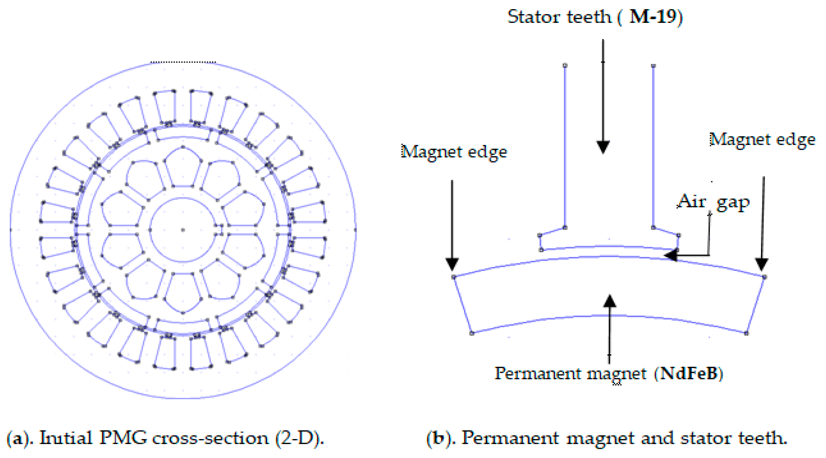
Figure 1 illustrates the initial general structure of the PMG.
Figure 1b shows the structure of the initial PMG used in this study, where the magnet is observed to be paired with conventional stator teeth at a spacing of 1 mm throughout the whole magnet rotor. It is important to state that the distance between the stator teeth and all magnet structure surfaces is the same as that in conventional stator and pole pairing. The maximum tangential magnetic density that may enter the stator slot is found at this magnetic point. This results in a huge CT because of the extremely high contact or attractive force between the magnet’s edge and the slot. This shows that the contact between the magnet surface and the stator core or slot may not be optimal for reducing the peak CT value. To limit excessive contact between the magnet’s edge and the slots in the stator core, it is necessary to restrict the range of the tangential magnetic forces acting on the magnet’s edge. An effective approach to reducing the extent of the tangential magnetic forces between the magnet’s edge and a slot in the stator core is to increase the air gap, which refers to the distance between the stator surface and the magnetic surface. The effectiveness of this method derives from the fact that by extending the distance between the magnetic surface and the stator slot, the air reluctance is reduced.
Therefore, some techniques need to be adopted to enhance performance, such as dummy slotting [
5,
25,
26], magnet edge shaping [
11,
27,
28], and magnet edge slotting [
29]. It is also possible to combine these techniques to ensure a greater improvement in PMG performance. For example, MES and PAO were combined in this study, as later presented in
Section 3.
2.2.2. The Structure of PMG Feature One-Step Slotting in the Magnet Edge
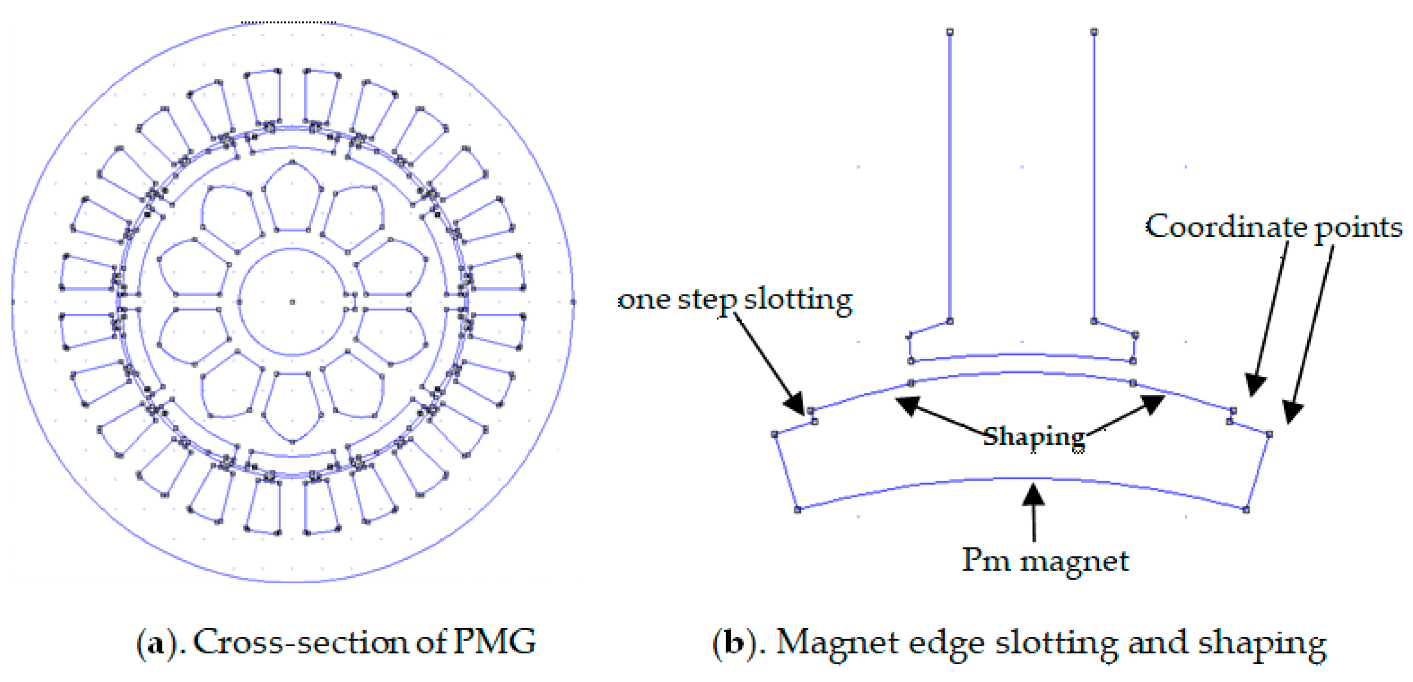
This article presents a reduction approach called the one-step slot method, which adds one step of dummy slots on the ends of the magnetic edges. The technique was applied in the original PMG, as shown in
Figure 2 below, where certain adjustments were made to the magnet’s edges.
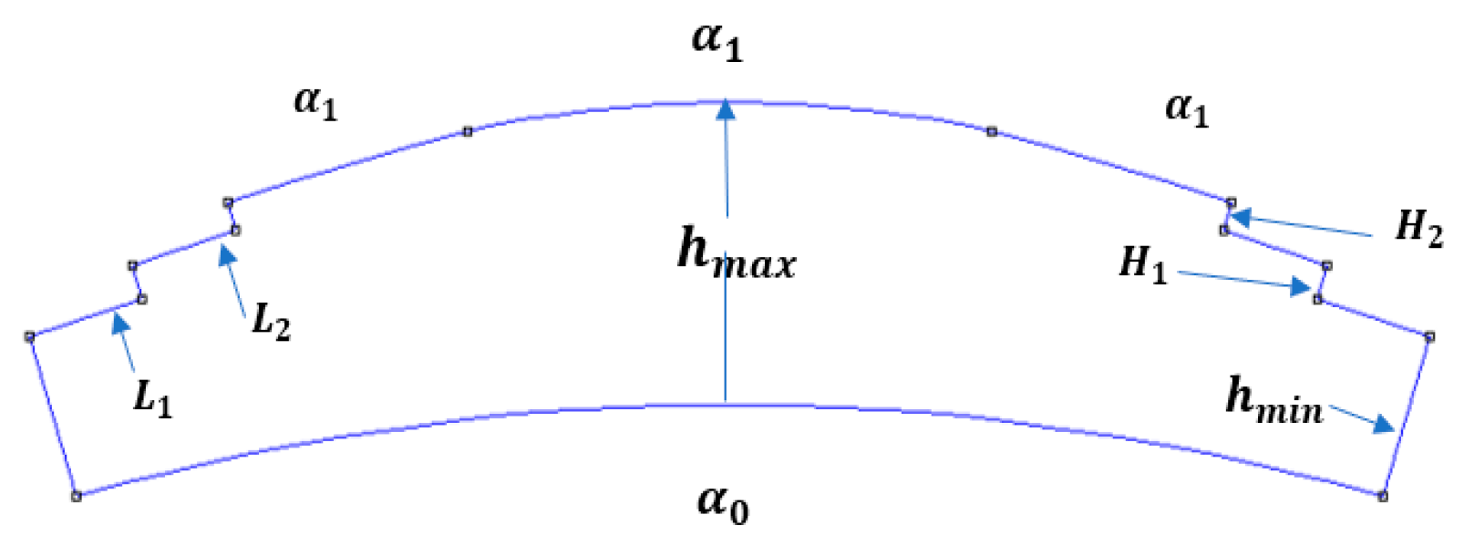
Figure 2 shows the PMG with magnet edge shaping on the constant stator teeth. It was observed that the shaping led to an increase in the spread between the magnet edge and the stator core. This subsequently increased the height of the air gap cross-section until it reached the initial structure, and this led to a decline in the air gap hesitation of the device. By employing both magnet shaping and magnet slotting techniques, it was possible to minimize the cogging torque effectively. However, the decrease in cogging torque was not substantial, as it remained at less than 98%. In the context of renewable energy systems, the cogging torque reduction required for PMG applications is a minimum of 98% compared with the original design state or when the PMG operates with a load. To achieve the greatest level of reduction, it is necessary to utilize a combination of current approaches or invent new ones. Following this rationale, the authors chose to transform the one-step slot into a two-step slot located on the edge of the magnet. By implementing a two-step slot on the magnet’s edge, several important changes occurred in its construction. First, there was a very significant increase in the area of the air gap at the edge of the magnet, which resulted in a significant decrease in the tangential magnetic flux from 0.3 Tesla to 0.135 Tesla. Second, because tangential magnetic flux density is one of the main causes of tangential magnetic force, the interaction that occurred between the edge of the magnet and the stator slot became weaker. Magnets at one pole are limited to one another (north and south poles) such that the tangential magnetic flux only flows through the rotor teeth.
2.2.3. Proposed Structure of PMG (Two-Step Slot Technique)
As stated previously, the increase in cogging torque reduction was achieved by altering the cogging torque reduction technique, implementing two slots instead of one slot on the edge of the magnet. The distance between the stator slot and the magnet’s shaped edge increased as this approach progressed. The flux distribution from the magnet into the stator slot and air gap progressively and ideally decreased under these conditions. Additionally, the adoption of the suggested approach is closely correlated with a greater distance between the stator core and the magnet. This approach has been researched as one of the cogging torque reduction strategies [
30].
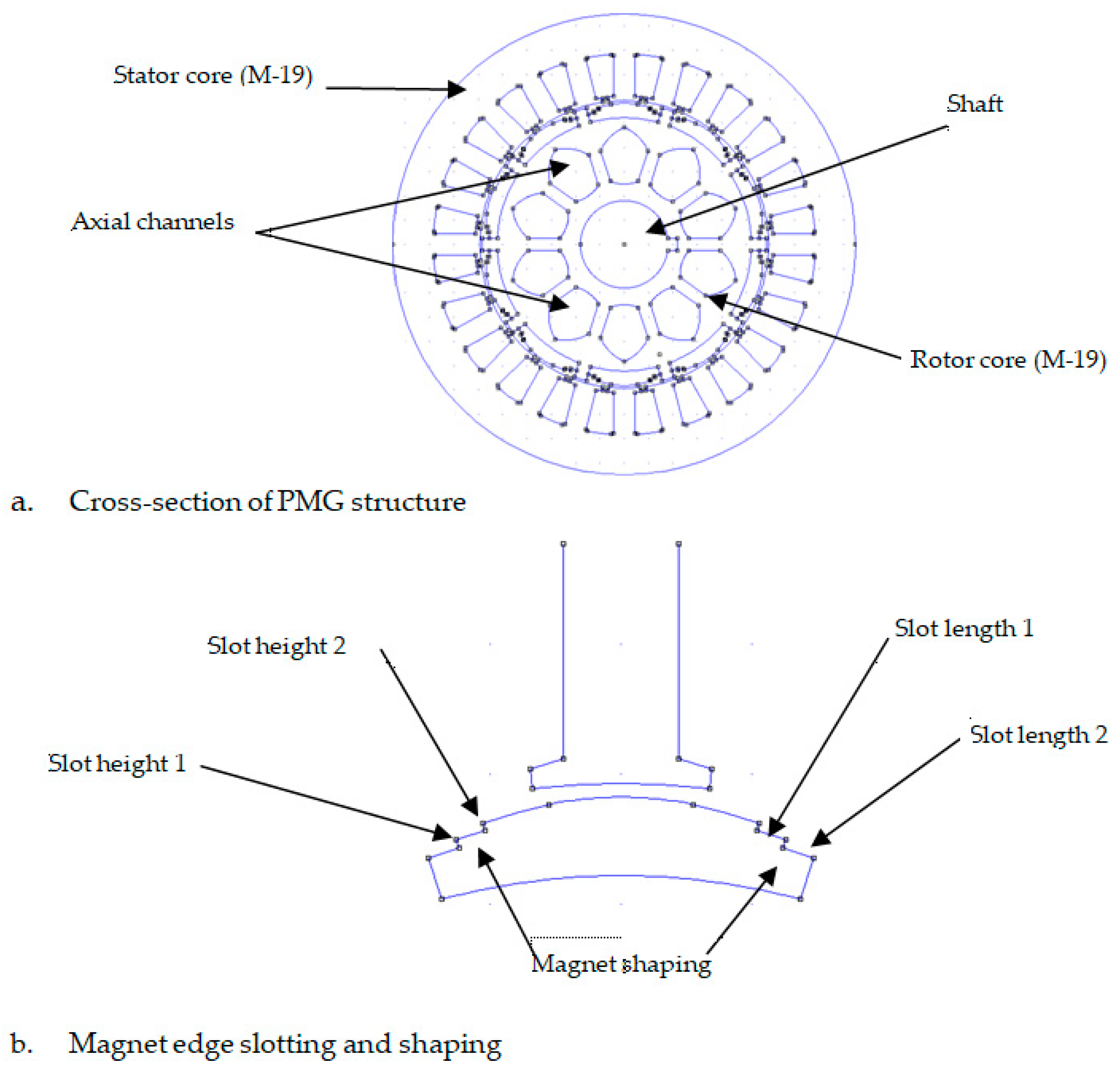
Figure 3 provides a detailed illustration of this method.
Figure 3 shows the use of the CT reduction technique for two slots on the edge of the magnet. Each edge of the magnet displays slots with two lengths and two heights. Additionally, the magnet’s shaping point shifts and tends to be within the range of the stator teeth. This is carried out to enhance the concentration of the normal magnetic flux density when it enters the stator teeth. Alternatively, when the shaping point shifts away from the stator tooth region, it results in a tangential magnetic flux density that penetrates the stator slot.
2.3. Simulation and Optimization Method of the PMG
A PMG with an FSN of 24 slots and 10 poles was applied in this study as the source of renewable energy. Some axial channels were also implemented in the rotor core, but the effect on PMG performance was not studied [
18,
19]. Moreover, the magnetic flux dispersal in the machining center was analyzed and distributed utilizing the finite part procedure founded on FEMM 4.2. The application of this method was associated with the confirmation of its ability to analyze any material with a complex structure, such as PMGs, as well as its accuracy. Furthermore, the proposed PMG structure was optimized by using the design of experiment (DOE) technique to determine the magnet rotor values. The accuracy of the CT measurement was assessed through the application of five dummy lines in the air gap of all constructed PMGs.
A suitable reduction approach is usually chosen based on the intended use of the PMG. CT may be reduced in PMGs by altering the construction of the stator, rotor, or both. For instance, thorough and efficient procedures are required for the use of PMGs in renewable energy solutions such as wind energy [
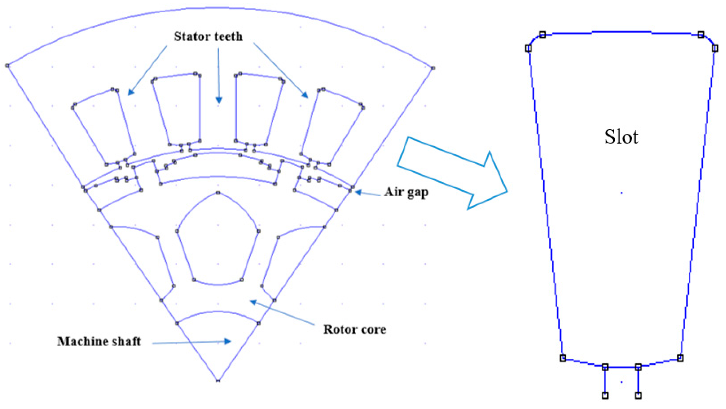
31]. This may be accomplished by combining many approaches, which will reduce each one’s drawbacks and produce better outcomes. Thus, as shown in blue in
Figure 4, this investigation entails two stages of slotting at the magnet edge.
This research aims to decrease CT by employing a CT-lowering technique that involves a two-step slot positioned at the magnet’s edge in a fractional-type GMP. This research utilizes a fractional type GMP with 24 slots and 10 poles, where the ratio between the slots and the magnets is a fractional number, namely, 24/10 = 2.4. In order to increase its application in wind turbine systems, the selection of 10 poles is a must as it permits usage at medium or low speeds.
Table 1 and
Table 2 present the modified PMG parameters used in this research.
This study presents an optimization technique that utilizes the Response Surface Method (RSM). The RSM is extensively employed in the field of optimization technology. A total of sixteen experimental designs were simulated using RSM optimization, with the optimum determined from the consideration of five parameters at the magnet’s edge with four levels. All these designs were applied in the two-step slots at the magnet edge, but the combination of sample length and sample height varied among each experimental design. Because of their differences, the coordinates of the mixed magnetic edges also varied.
The optimization parameters employed in the RSM approach are outlined as follows:
H1 (height of the edge of magnet 1);
L1 (length of the edge of magnet 1);
H2 (height of the edge of magnet 2);
L2 (length of the edge of magnet 2);
The surface angle at the edge of the magnet.
All parameters were assigned a rating on a scale of 1 to 4. For instance, L1 represents the length of the cutting edge of magnet 1, with values ranging from 2.00 to 2.75 in increments of 0.25. Furthermore, 2.00 is referred to as the initial or minimum rank, succeeded by 2.25 as the second rank, 2.50 as the third rank, and 2.75 as the fourth or maximum rank. H1, also known as the height of the cutting edge magnet 1, begins with a minimum value of 0.5 and progresses to a maximum rating of 0.8, with intermediate values of 0.6 and 0.7. The implementation of L2 and H2 is identical to that of L1 and H1. The magnetic edge angles range from a minimum of 20 degrees to a maximum of 3.50 degrees, with intermediate values of 2.50 and 3.00 degrees. The Response Surface Method (RSM) asserts that when all factors are combined with four levels, it produces a total of 16 designs. The cogging torque (CT) values generated by the 16 designs were observed by simulation. Each design’s CT value was compared to the original design’s CT. We completed the analysis with FEMM, achieving a high level of precision (1/108). For every design, we incorporated a simulated line within the machine’s air gap to prevent the collection of imprecise measurement data. FEMM 4.2 is commonly employed for validating the design of various electrical machines, such as DC machines and transformers.
FEMM 4.2 software was used for simulation to derive the minimal CT from the method design and data presented above. The acquired normal and tangential magnetic flux measurements, as well as the CT comparison of the three PMGs mentioned above, are covered in the Results Section.
3. Results
Similar to the methodology employed in previous work, magnet trim shaping and form slotting were implemented on the stator core [
2,
22,
23]. Owing to the intricate geometry and existence of non-uniform regions that lead to numerous boundary conditions in these systems, the analytical computation of PMGs is sometimes very challenging. This prompted the idea of taking the SOW impact into account to precisely depict the magnetic area in the PMG’s air gap. Furthermore, it has been determined that the analytical method is the most preferred approach for optimizing PMG designs under all conditions. This is explained by the fact that all parameters in mathematical equations have direct relationships with one another, as well as with perceived observations. To ascertain the magnetic occupancy based on the schematic diagram in
Figure 5, the PMG structure was separated into SR, as shown in the figure below.
R1 is the distance from the lowest height of the magnet to the rotor center, R2 is the distance from the maximum height of the magnet to the rotor center, R3 is the space between the rotor center and the stator shoe surface, R4 is the distance between the rotor center and the stator tooth, and R5 is the space between the rotor center and the base of the slot.
The three radii of the stator core surface (R
s), magnet surface (R
m), and inner rotor (R
r) were used to roughly describe the architecture of the inner rotors in the PMG examined in
Figure 5 and
Figure 6. This study was performed under the assumption that the demagnetization properties of the lasting magnet material were in a linear working region and that the rotor back iron and stator yoke had infinite permeability. In addition, the area of explanation was divided into four regions as follows: region 1 represents the first layer of the magnet, region 2 represents the second layer, region 3 represents the third layer, and region 4 represents the engine’s air gap.
After applying the scalar magnetic potential, the following mathematical equations were shown in relation to the magnet area and air gap in opposite coordinates:
where
to
are the scalar possibilities in every area,
M represents the magnetization vector in the interests of the machine, and
is the comparative permeability of the magnets. The magnetization vector of the magnet is formulated as follows:
The electromagnetic domain was investigated in both 2-D and polar dimensions in
Figure 1b, where the PMG was taken to be outside of the saturation position. According to this assumption, there was only one element in the axial movement of magnetic vector prospect A, the rotor and stator iron’s permeability was unlimited, and the magnet’s demagnetization element was linear. In addition, the sides of the slots had a completely radial orientation, the comparative permeability was equal to unity, and the polarization vectors of the permanent magnets (PMs) were assumed to be completely radial.
A further evaluation of the PMG using the SD approach can be seen in
Figure 5 and
Figure 6. Instead of using stator slot simplification, as previously carried out in [
2,
22,
23], this approach has the benefit of taking into account the real SOW, as well as the effects of the stator shoe peak and width. These investigations were divided into three areas as follows: the first contained the magnets and was bounded by the radii R
1 ≤ R
2, the second contained the air gap within R
2 ≤ R
3, and the third included all of the machine’s stator slots situated within R
3 ≤ r ≤ R
5. Nevertheless, the current study only investigated the PMG electromagnetic lot in the R
2 < R
3 region of the air gap.
The sub-domain approach was utilized with the aimed of solving the Maxwell equation directly in various sub-domains, such as air gaps, stator locations, and PMs, by using variable separation. The magnetic field was introduced into each region according to the interface and edge states. Likewise, the analysis of the PMG was conducted on the assumption that there was no airflow in the stator coil. This led to the utilization of the Laplace equation to calculate the distribution of the magnetic field in other components, such as the stator and air hole. The differential equation in each region is expressed as follows:
For the first region in the air gap,
as well as for second, third, and fourth regions.
µ
0 represents the permeability in the free space, and
M denotes the magnetization of a permanent magnet composed of either two components or one, depending on its magnetization. However, this study assumed a zero tangential value, as the magnetization was considered to be radial. This was stated in polar coordinates as follows:
The following equations link the magnetic change thickness and the magnetic field vectors B and H in these areas:
The radial and tangential flux densities of the PMG were assumed from magnetic vector possibility A as follows:
The radial flux density was determined using Equation (12):
Based on the parameters of the PMG, the normal flux density was formulated as follows:
The tangential flux density was defined as presented in Equation (14)
Both the standard and tangential magnetic fluxes contributed magnetic force in the air interval of the PMG, as presented in Equations (15) and (16), respectively.
The magnetic flux viscosity in the PMG acted perpendicular to the stator teeth, while the divergent flux density moved into the slot space of the stator core, resulting in the formation of divergent force in the air gap of the appliance. Furthermore, the CT value of the PMG was influenced by the larger normal tangential force that was applied to the air gap as a result of the magnets producing a greater tangential flux density.
Equation (16) provides the formula for the tangential magnetic flux density (
Ft):
A comparison was made between the characteristics of both the normal and diverging magnetic flux densities of all the PMGs analyzed. A reduction in the amount of magnetic flux, primarily of the normal type, entering the PMG’s air gap was caused by the magnet edge’s shape, which also altered the structure’s magnetic flux distribution. Furthermore, the tangential magnetic flux circulated within the rotor teeth or core instead of flowing into the air gap. This circulation resulted in a decrease in the perpendicular flow into the slot opening of the machine, which, in turn, led to a reduction in the tangential force.
3.1. Effect of Magnet Structure on the Magnetic Flux Distribution of Machines
The performance of the PMG was simulated using FEMM version 4.2, following the methodologies employed in previous research [
24,
30,
32,
33,
34]. The steps and methods are depicted in
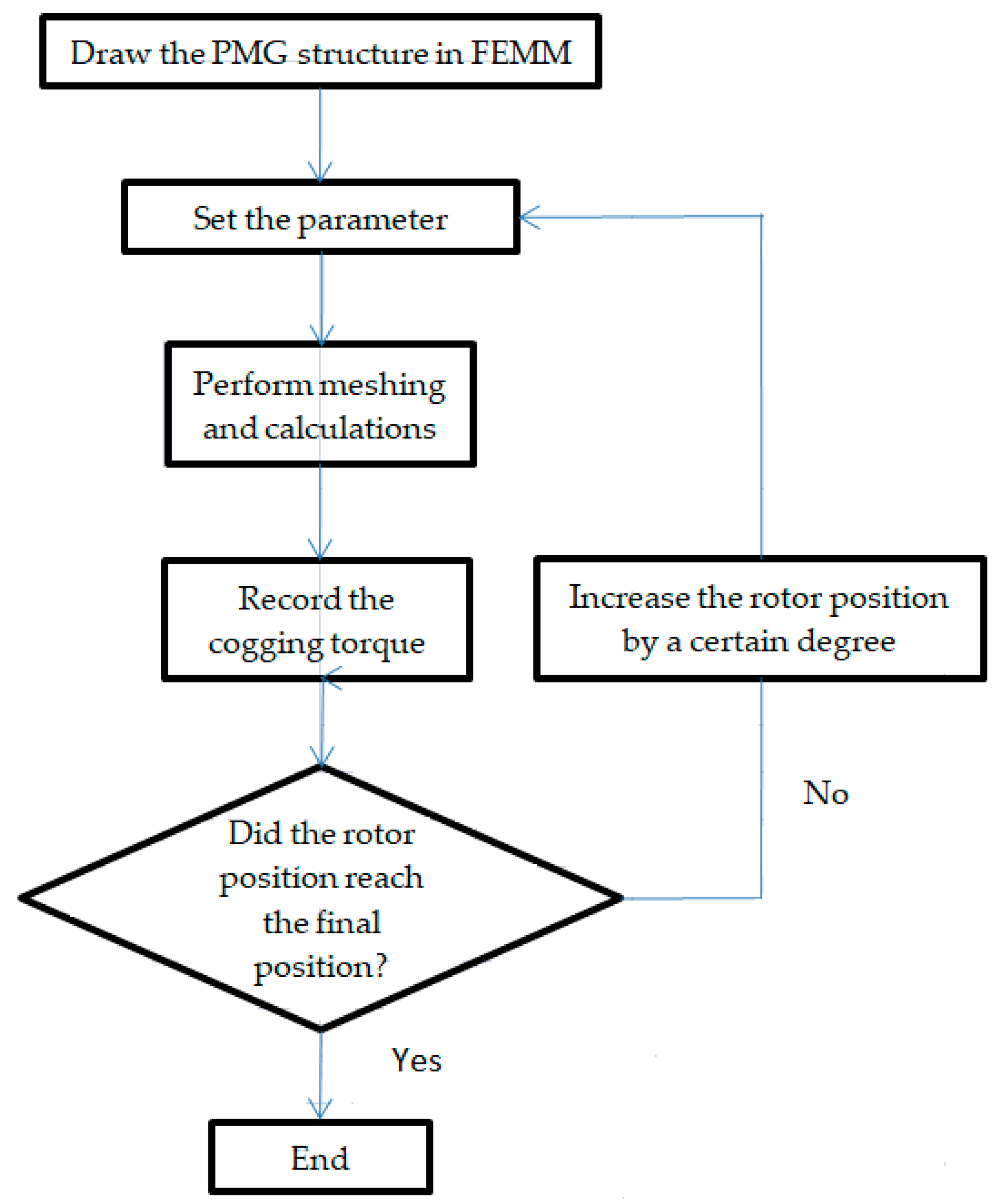
Figure 7, and LUA 4.0 scripting was used to reduce mistakes in the simulation.
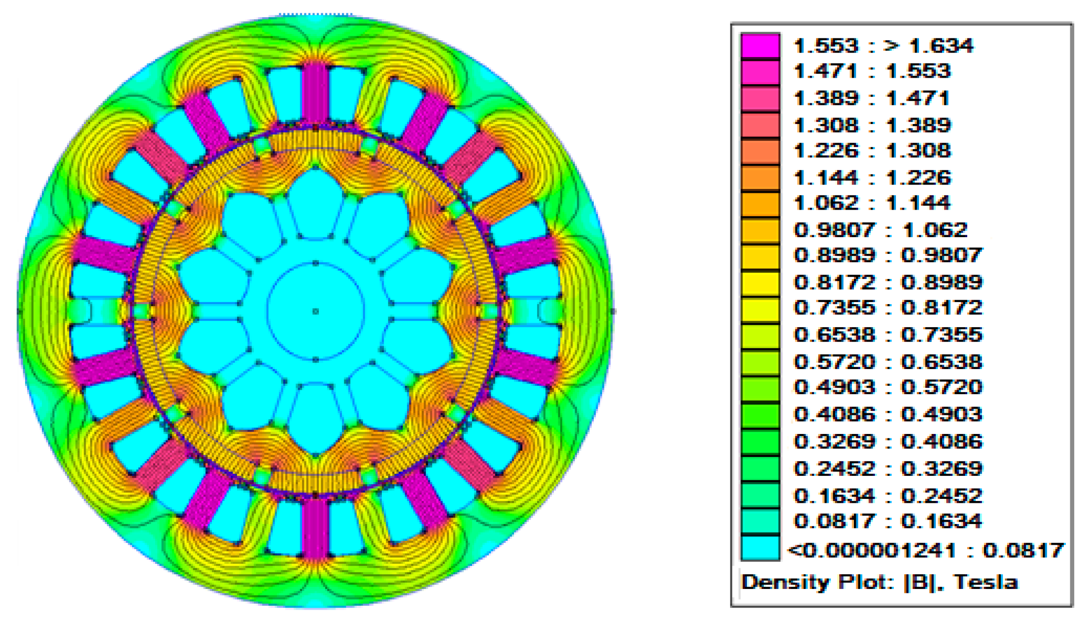
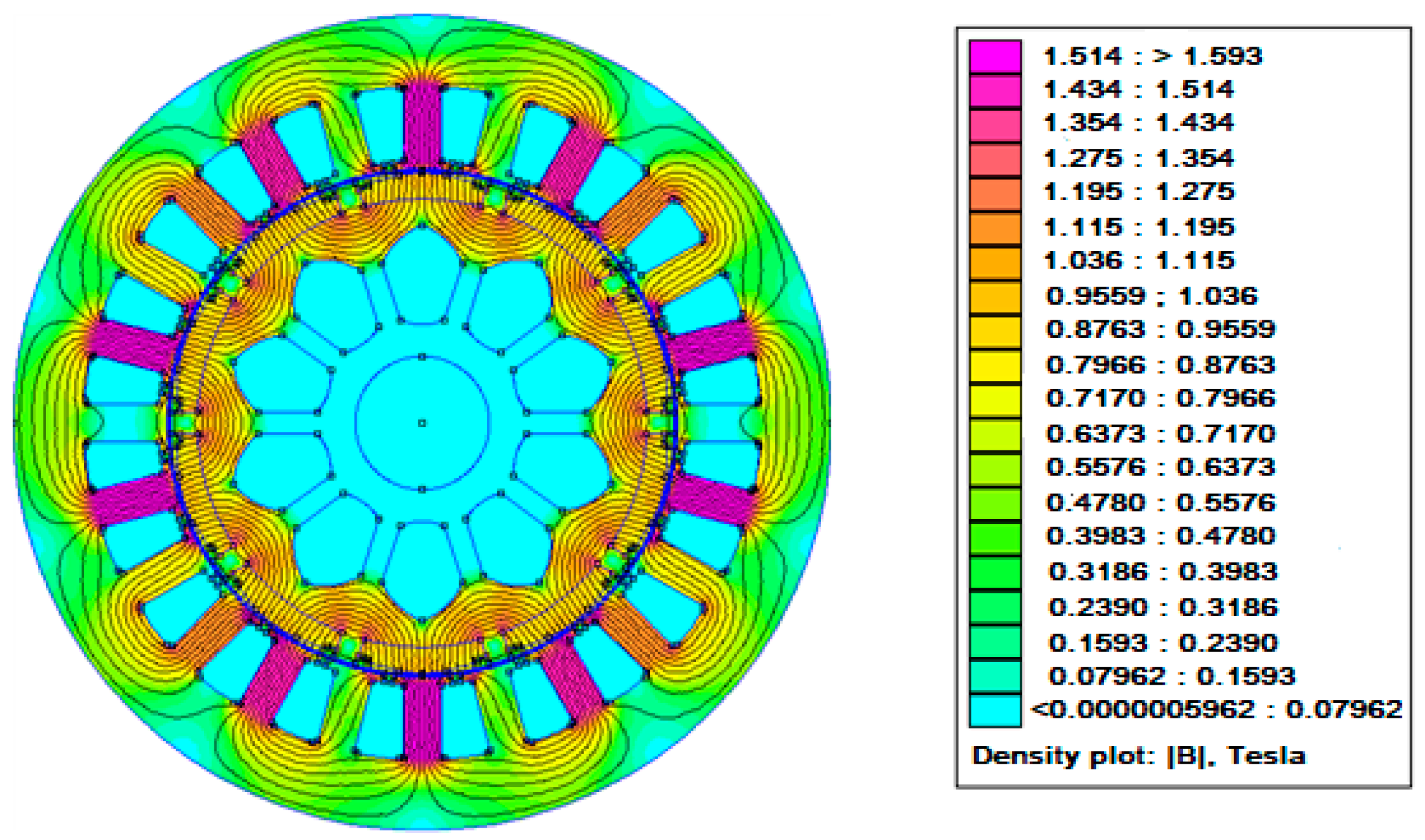
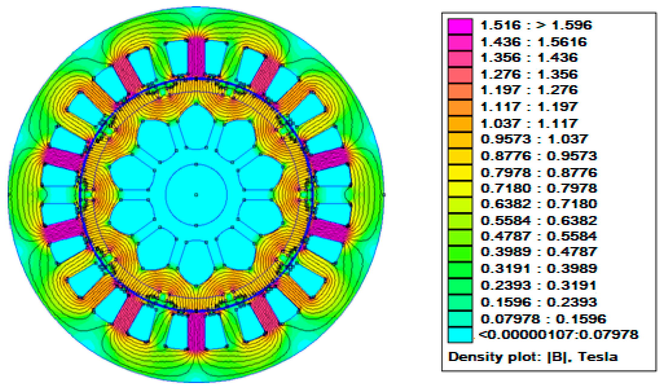
The performance of the PMG was shown to benefit from the application of this combination strategy in a number of ways. First, the air gap’s tangential flux viscosity was decreased by the magnet edge shaping. Second, the reluctance was significantly reduced as a result of the air gap cross-section being raised by the adoption of a dummy slotted core. Third, eddy current losses were reduced in comparison with those of typical magnet configuration because of a drop in the magnetic flux density in the machine’s stator and rotor core. However, as a rule of thumb, the power output of the machine was reduced considerably because the volume of the magnet became smaller as the magnet edge was shaped. The process of modifying the magnet edge also resulted in a decrease in the maximum tangential flux density from 2.1 Weber to roughly 1.5 Weber. To ensure accuracy in the process of measuring the CT values, five dummy lines were formed in the air gap in addition to using an R value of 11.8849 cm from the center of the PMG in this investigation. By increasing the number of dummy lines, the magnet flux path cross-over between the stator core and magnet structure was reduced, improving measurement accuracy. The magnetic flux densities in the center of the first system, in a regular magnet with dummy slotting in the stator core, and in a shaped magnet edge in conjunction with dummy slotting in the stator core are shown in
Figure 8,
Figure 9 and
Figure 10, respectively.
Because of the addition of the two-step slot at the magnet edge, the proposed structure in
Figure 8 had a magnetic flux density of 1.516 Tesla compared with the estimated 1.553 Tesla of the baseline structure in
Figure 8. The value was further decreased to around 0.7889 Tesla by combining magnet edge shaping and dummy slotting in the stator core (
Figure 10).
3.2. Effect of Magnet Structure on the Magnetic Flux Distribution of Machines
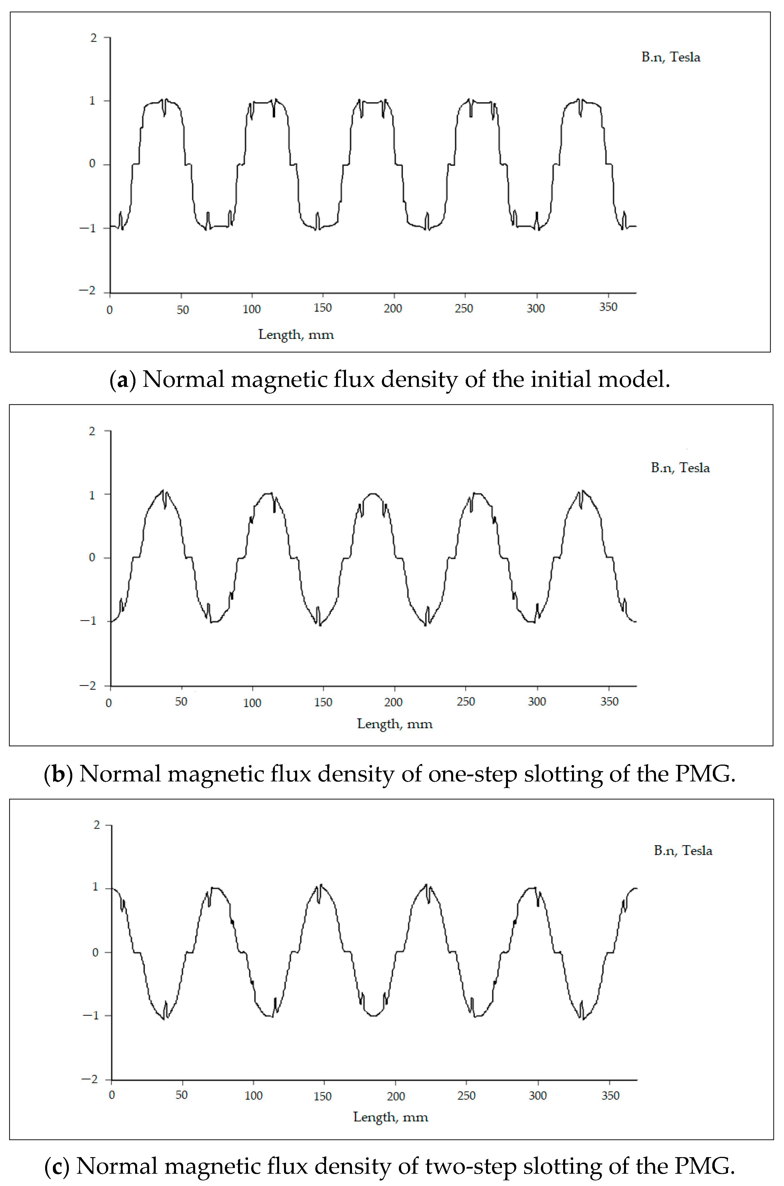
Figure 11 shows the effect of both non-step slotting and step-slotting at the magnet edge on the magnetic change diffusion in the PMG air gap under study. In
Figure 11a–c, the normal magnet flux density of the PMGs under study is displayed.
Figure 11a illustrates the magnetic flux density of the first GMP design. The normal magnetic flux density is often represented by a rectangular shape. The square form of the magnetic flux signifies that the usual magnetic flux will penetrate both the stator teeth and the stator slot simultaneously. The magnet’s edge and the stator slot are attracted to each other because of the introduction of magnetic flux into the slot. By inserting the magnet’s edge into a slot, the amplitude of the usual magnetic flux density reduces. Consequently, the magnetic flux density takes on a sinusoidal pattern. Maximizing the sinusoidal form of the normal magnetic flux may be achieved by creating a two-step slot at the edge of the magnet. In addition, the presence of two slots results in a dramatically reduced flux level near the edge of the magnet compared with the scenarios where there is only one slot or no slot at all. This can greatly diminish the contact between the magnet’s edge and the slot.
The space between the magnet edge and the stator teeth increased as the magnet frame’s perimeter decreased, as shown in
Figure 11. As a result, the air gap reluctance of the device decreased, as previously noted, and the air gap cross-section became bigger until it approached the original structure. As for any electric machine construction, one of the most important factors to take into account in order to lower the peak CT in PMGs is the air gap reluctance. A higher number of contact points between the stator teeth and the magnet structure was also seen when dummy slotting was added to the stator teeth. This approach resulted in an increase in CT frequency and an elevation in the peak CT value. The key to achieving a greater CT reduction in PMGs is to optimize the point contact number location and magnet pole arc as this reduces the magnetic flux thickness in the core. Since the magnet’s volume decreased, this method is thought to be acceptable, even though it can lower the machine’s energy production when compared with the original configuration.
Furthermore, the distributions of the tangential and normal magnetic flux densities are distinct. The tangential magnetic flux is directed towards the stator slots, whereas Bn is oriented towards the stator teeth. An interaction, or attractive force, is created between the stator slot and the magnet’s edge or end when the tangential magnetic force and the slot meet. Increasing the width of the stator slot leads to stronger contact between the magnet’s edge and the stator slot, resulting in a higher magnitude or peak value of the cogging torque. Consequently, an excessively wide stator slot is not desirable. In the present study, the slot width was fixed at 2 mm, and the spacing of the stator teeth, the slot, and the magnetic surface of the first design generator were all set to 1 mm.
The distance between the magnetic surfaces, or magnet edges, steadily enlarges after the cutting at the edge of the magnet. The tangential magnetic force that reaches the stator groove naturally decreases with increasing distance between the magnet’s edge and the stator slot. Meanwhile, the tangential flux that occurs at the magnet’s edge is greatly decreased by the existence of fractures on the magnet’s surface.
3.3. Cogging Torque Calculation
The theoretical explanation of the two-step slot method is as follows; magnetic flux, which is generated when flux from the north magnetic pole (N) travels to the magnetic south pole (S), will link a pair of magnets that have north and south poles. An orthogonal tractor line of magnetic force is formed by the flux distribution path from the north magnetic pole to the south magnetic pole. These lines are parallel and do not meet at a single point; instead, they each create a point when they reach the south magnetic pole. The total flux entering the air gap reaches its maximum level when the stator teeth or rotor magnets are not treated in generating systems (carrying, trimming, dummy slots, etc.). Additionally, the machine air gap might show reluctance at certain moments. Therefore, CT increases significantly. Theoretically, this may be explained by Equation (17) [
24]:
where
denotes CT,
represents the total magnetic flux entering the air gap,
is the reluctance of the air gap, and
represents the mechanical angle of the magnet rotor movement. The relationship is directly proportional to the amount of tangential magnetic force at a specific radius of the rotor and the length of the rotor or machine. From a mathematical viewpoint, this may be clarified by Equation (18) [
24]:
where
Lstk is the length of the rotor/machine or generator,
r represents the rotor radii, and
Ft denotes the tangential magnetic force.
The CT values were later determined from the radial and tangential magnetic flux viscosity in the air gap area by utilizing the Maxwell Stress Tensor (MST), as shown in Equation (19) [
2,
35]:
where
is the effective PMG length,
R is the place in the air gap where CT is computed, and
is the normal or radial flux thickness.
The equation demonstrates that several significant factors affect the CT value of PMGs; nonetheless, the standard and digressing magnetic flux densities are the most significant factors because they both change with time. Both tangential and regular flux densities were found to be produced by the rotation of the rotor. The normal force created in the air gap by the conventional magnetic flux density acted perpendicular to the stator teeth. Meanwhile, perpendicular to the stator slot opening, the tangential magnetic flux density acted to increase the tangential force in the air gap. This suggests that the combination of the two factors resulted in the overall magnetic force in the air gap. Consequently, the combination of magnet edge shaping and figure slotting in the stator core was necessary to minimize the CT, and this called for the consideration of an acceptable stator or rotor construction.
Figure 11 shows that the normal flux density of the proposed PMG maintained a constant height, as observed in the initial design. Nevertheless, the tangential flux density reached its highest point, although it decreased significantly, particularly when compared with that of original design depicted in
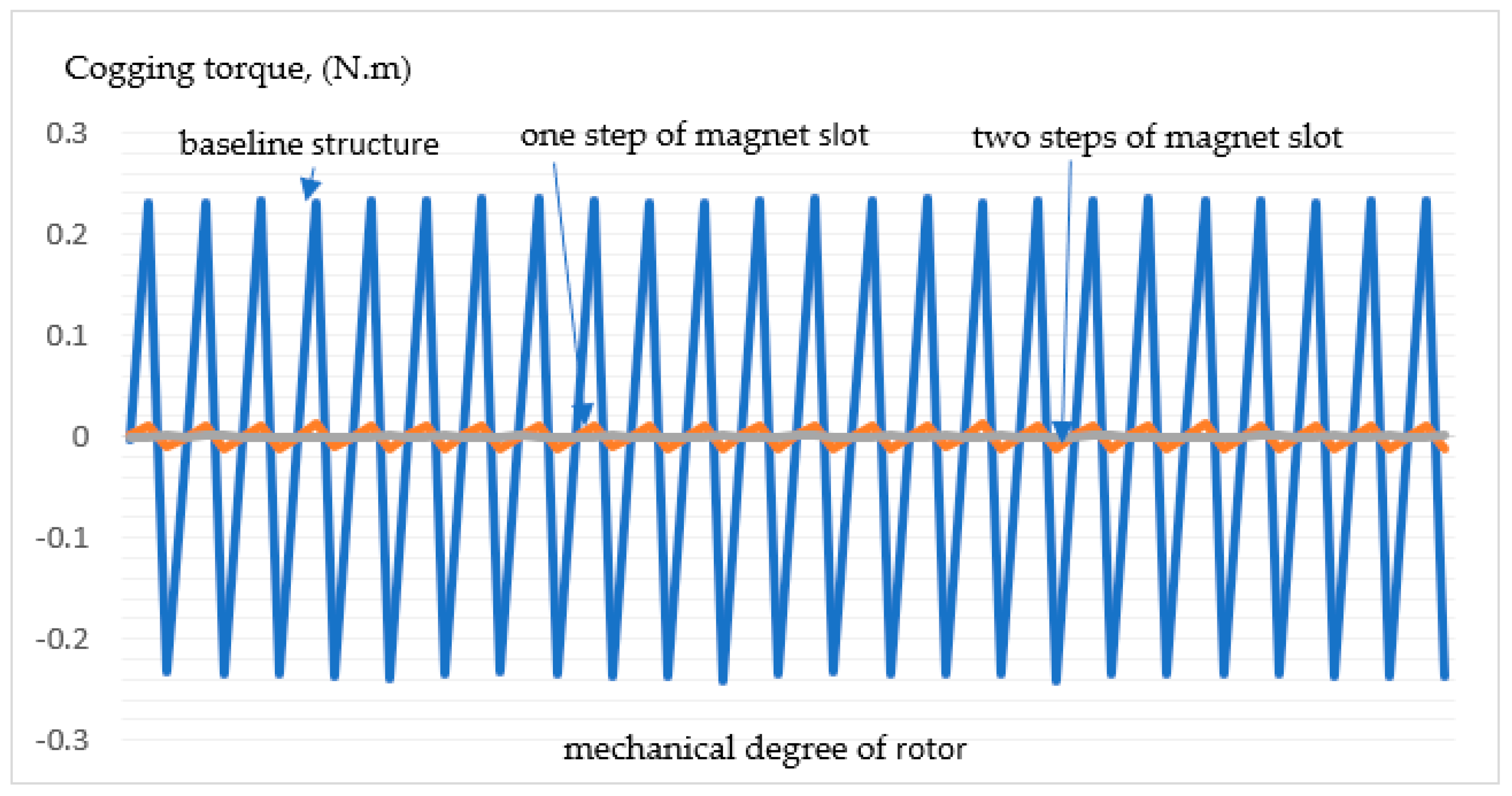
Figure 11a and Equation (9). Moreover, additional significant decreases were observed in the CT, as shown in the comparison of the three PMGs in
Figure 12.
The magnetic flux diffusion of the PMG was calculated using the finite element method, as shown in
Figure 10. In comparison with the other PMGs investigated, the results indicate that the peak value of the CT in the first construction was the greatest at 0.2341972 Tesla. This was linked to the increase in the air gap and the consequent, practically caused decrease in reluctance as a result of dummy slotting, which caused the CT to drop to 0.0145543 Tesla. The proposed construction of a magnet edge with two-step slotting also showed a noteworthy reduction of 0.0006905 Tesla.
4. Discussion and Conclusions
In conclusion, this study presents a novel technique that can be used to increase the enactment of the proposed structure with 24 slots and 10 poles for PMGs. The peak CT of the conventional structure was found to be 0.2341972N using a finite element analysis, but the value reduced significantly to around 0.0145543 Nm because of the introduction of one-step slotting, a natural technique for reducing CT. Moreover, the implementation two-step slotting at the magnet edge led to a significant reduction in the CT value to 0.0006905 Nm. Thus, the percentage reduction in the dummy-slotting technique compared with the conventional structure was [100% − (0.0145543/0.2341972)] = 100% − 6.21% = 93.79%, while the percentage reduction in the proposed combined structure technique was [100% − (0.0006905/0.2341972)] = 100% − 0.294837 = 99.71%. The CT decrease was higher than that observed in comparable investigations, with a magnitude of 98% [
36]. The results demonstrated that an effective reduction in the machine’s CT was achieved by using the developed reduction technique for the 24-slot/18-pole structure. Therefore, it was concluded that the implementation of magnet edge slotting and dummy slotting in the stator core could significantly decrease the CT of the proposed structure.
The suggested PMG method was implemented more effectively because of the considerable reduction in CT that was achieved by combining magnet edge shaping and dummy slots. This was related to the method’s capacity to lower the magnetic flux density in the machine core from 1.553 Tesla in the ordinary construction to 1.516 Tesla, which resulted in a slight decrease in eddy recent losses. This happened as a result of the magnet volume decreasing relative to the original design magnet volume because of the two-step slot on the magnet’s edge. This reduced the magnetic flux entering the stator teeth by optimizing the overall flux entering the machine air gap.
Furthermore, by applying the two-step slot technique to the magnet’s edge, a new magnetic edge was formed, in addition to reducing the magnet’s volume and restricting the flux entering the stator teeth. As a consequence, the magnetic flux flowing in the rotor teeth and the flux entering the stator teeth were distributed equally. Additionally, the distance between the trimmed portion of the magnet and the slot progressively changed from 1 mm to 2.7 mm when two-step slots were applied to the magnet’s edge and then the magnet’s end was trimmed. Consequently, there was more strong or frequent contact between the magnetic edge and the stator slot. Furthermore, the cogging frequency increased because of the two-step slots on the magnet’s edge, yet the cogging torque reduced in magnitude.
The FEMM study showed that from the initial condition of 0.3 Tesla to around 0.135 Tesla, the tangential magnetic flux density at the magnet’s edge dropped by 55%. This was because the reduced material meant that, in comparison with a magnet without a dummy slot, there was a greater gap between the magnet’s edge and the stator slot or magnetic surface. In this way, it could be confirmed that the tangential flux density at the edge of the magnet decreased drastically, so the tangential magnetic force that caused the attraction between the edge of the magnet and the stator slot became very small. Therefore, the tangential magnetic flux density only circulated in the rotor teeth. The existence of magnetic flux circulation in the rotor teeth is part of the process of transferring flux from one pole to another in machine design.
The generator design in this paper adds slots to the edge of the magnet, transforming it into a bread loaf shape. The magnet architecture proposed in this work has a curved bottom surface, which is a frequent characteristic of electrical equipment that uses permanent magnets. Before inserting the magnet into the rotor body, a two-step slot implementation is performed. This simplifies the manufacturing process. The bread loaf magnet’s architecture offers two advantages. First, it is still simple to install a bread loaf system in the slot of the rotor core even if it has a slightly curved bottom or base surface. There are no technical issues, and the situation is the same as it was in the earlier manufacturing of electric machines. To prevent demagnetization of the magnet structure, the height of both magnet edges is kept high. The magnetic structure remains undamaged by a shock event that occurs during rotor rotation. It is possible to control the volume of the magnetic adhesive that is inserted into the slot to guarantee that each groove has the same amount of glue. It is anticipated that this glue will give the rotor slot magnetic strength, preventing magnetic flux distortion brought on by the adhesive’s thickness. Conversely, flux distortion will happen if the adhesive thickness on the magnet’s base surface varies in volume or thickness since the magnet will see the adhesive as an insulator. Second, by cutting slots in the magnet’s edge, the flow of magnetic flux in the machine air gap is maximized and the rotor teeth’s flux distribution is controlled. As a result, cogging torque is decreased by lessening the attractive force between the magnet’s two edges and the stator groove. Reduced tangential magnetic flux, sharply reduced contact between the magnet’s edges, and a notable decrease in cogging torque are the results of the magnet’s edge being reduced to the form of a slot.
The GMP structure presented in this study is a generalized version of an ordinary GMP. This structure may be implemented in practical applications, and the outcomes can align with the results suggested in this study. It is essential to ensure that all parameters meet the requirements properly. Furthermore, the production process must adhere to contemporary electrical machine manufacturing standards. Additional factors that influence the quality of the output include the following:
The surface of the stator teeth.
The surface of the stator teeth should possess a smooth texture, devoid of any roughness. It is essential to avoid any bias in the direction of the magnetic flux that enters the stator teeth. An uneven magnetic surface will interfere with the correct dispersion of the magnetic flux that passes through the stator teeth, resulting in alterations in CT.
The glue or the adhesive over the magnet’s surface.
To avoid detachment from the rotor during GMP operation, the glue or adhesive on the magnet must possess both strength and uniform thickness. If the viscosity of the glue is extremely high, it has the potential to function as an insulator, disrupting the circulation of the magnetic flux within the core. This has the potential to result in an alteration in the distribution of the magnetic flux that enters the air gap. A deviation from the predicted machine performance may occur in the resultant CT value because of this circumstance.
Spikes exerting pressure on the stator and rotor cores.
The stator core is made up of many laminates that are 0.3 mm to 0.5 mm thick and held together by nails. A specific amount of pressure must be exerted throughout the application process. These laminations must be held together under intense pressure to reduce the amount of air that enters the space between the laminations, stator core, and rotor. Moreover, too much pressure may cause the insulation around the core to rupture, which would change the way the core channels produce magnetic flux in the generator system.
Problems with coordinate points or magnetic flux centers.
This study assumes that the magnet’s center is the center of the magnetic flux. In this scenario, the magnet receives the flux at a balanced point between its top and bottom, along with the coordinates on its right and left. Additionally, the north-pole must be exactly at the 90-degree angle, in contrast to the south-pole at −90 degrees. If this condition is not satisfied, the interaction between the north and south poles will still influence the direction of the magnetic flux distribution. The CT two-step slot reduction technique is used on the magnet’s edge with the aim of reducing the intensity of the tangential magnetic force from the magnet’s edge to the stator slot. Experience shows that using this strategy can lower the amplitude and tangential flux density near the magnet’s edge by 50–60% when compared with the original design. Employing a one-step slot can greatly decrease the amplitude peak, but the tangential magnetic flux density remains reasonably high. Thus, if the one-step slot approach is not combined with additional methods, such as employing dummy slots on the stator teeth, the reduction in CT is not as significant as that of the two-step slot technique.
