Abstract
The increasing penetration of renewable energy sources (RESs) in transmission and distribution systems presents several challenges for grid operators. In particular, the unpredictable behavior of RESs can disrupt the balance between energy production and load demand, potentially affecting the stability of the entire system. Grid-connected energy storage systems (ESSs) offer a possible solution to manage the uncertainty associated with RESs. In fact, ESSs exchange power with the grid through the adoption of suitable energy management strategies, which are typically implemented by power electronics-based grid interfaces. Unlike other current source converter (CSC) solutions described in the literature, which only interface with a single energy storage device, this paper introduces a novel topology for a three-phase delta-type current source converter (D-CSC), which is capable of integrating three independent ESSs using the same number of semiconductors as traditional CSC solutions. Thus, it considerably enhances the flexibility of a power conversion system (PCS) without increasing the number of converter components. In addition, an innovative energy management control strategy is also introduced. This strategy enables the D-CSC to compensate for energy imbalances arising between the three ESSs, which might be caused by several factors, such as different aging characteristics, converter component tolerances, operating conditions, and temperature drifts. Hence, the D-CSC-based interface is capable of proper grid operation even if the three ESSs have different characteristics, thus opening the possibility of employing this converter to integrate both first and second-life devices. First, the topology of the proposed D-CSC is introduced, followed by a detailed mathematical description of its control strategy. The proper grid operation of the D-CSC was tested under different scenarios, considering the grid integration of three independent superconducting magnetic energy storage systems in a marine vessel. The proposed D-CSC is compared to traditional CSC solutions, highlighting the superior performances of the novel converter topology in terms of efficiency, total harmonic distortion of the output currents, and overall cost reduction for the PCS.
1. Introduction
In recent years, the increasingly impending need to stop climate change has motivated governments, researchers, and companies to make unprecedented efforts to convert the energy production sector from traditional fossil-fuel-based sources to renewable energy sources (RESs) [1]. However, as the penetration of RESs increases, the management of power systems becomes more challenging. Indeed, the rather unpredictable behavior of these energy sources makes it harder to balance the energy production with the load demand, eventually affecting the stability of the entire system. Therefore, power grids are increasingly relying on energy storage systems (ESSs) because these play a key role in coping with the uncertainty associated with both the availability of RESs and behaviors of energy consumers [2].
Several storage technologies based on different physical principles have been developed throughout the years to exploit the energy storage capabilities of different methods, such as chemical, mechanical, and electromagnetic technologies. Nevertheless, the common role of all grid-connected ESSs is to operate as “energy buffers”, absorbing power from the grid when the production exceeds the demand or, vice versa, injecting power when the RES-based production is insufficient, thus actively matching the energy production with the load consumption. This power exchange can be suitably controlled through a power electronics-based power conversion system (PCS), which serves as the interface between the ESSs and power grid. Among the available ESS technologies, superconducting magnetic energy storage (SMES) has been proven to be a suitable option for a plethora of applications, effectively providing grid services such as power fluctuation compensation, frequency control, transient stability enhancement, and power quality improvements of grid-connected renewable energy systems such as wind energy and solar photovoltaic systems [3].
This study was conducted within the framework of V-ACCESS, a European project supported by the Horizon 2020 program. The scope of this activity is to investigate the opportunities and feasibility of integrating SMES on marine vessels to support the onboard electric grid. This has the primary goal of supporting the batteries that are already present in different vessels to improve the overall efficiency and reduce the battery size. Moreover, the high peak power that SMES can supply could improve the quality of the onboard electric grid, allowing the integration of new devices and expanding the maneuverability of the vessel. In order to integrate SMES in a ship’s electric grid, it is necessary to develop suitable converters with high performance, limited cost, and the potential to integrate more than one SMES in the ship. For this reason, this paper proposes a new current source converter that can integrate three SMES systems in a single power conversion system.
Regarding SMES integration, several viable solutions can be found in the literature to realize a PCS based on a current source converter (CSC) topology because of the inherent constant current source behavior of SMES devices. The authors of [4] proposed the adoption of a single-phase CSC-PCS for SMES integration, demonstrating the feasibility of achieving a bidirectional power exchange according to load and network requirements. In [5], multiple parallel-connected CSCs were employed to increase the system power exchange capability and realize a 20 MW PCS interfaced with a single SMES device. A similar solution was presented in [6], where several SMES devices exchanged energy with the AC grid through the use of a dedicated CSC for each SMES coil, demonstrating the operation of several SMES-fed CSCs in islanding mode.
Moreover, SMES units are successfully used in the specific context of marine power systems and, more generally, in naval applications, usually in combination with other storage devices. This was the case in [7], where a hybrid ESS (combining SMES and batteries) was proposed for peak and pulsed load supply. A similar employment of SMES for marine power systems was also found in [8], where the authors exploited this storage technology to control the DC bus voltage of a power converter under peak load conditions. A possible application of SMES can also be found in naval DC microgrids, where model-predictive control strategies for the ESS have been implemented for efficiently managing the available energy, with particular reference to pulsed-power load supply [9].
CSCs are also suitably employed for integrating other storage technologies. Indeed, the authors of [10] presented a three-phase grid-connected CSC integrating battery storage systems to realize a charging station for electric vehicles. Regarding hydrogen-based ESS, [11] adopted a CSC that could be suitably employed for the grid integration of a fuel-cell storage plant. In this context, modular multilevel CSC topologies have also been investigated, as in [12]. Other PCS solutions based on CSC have also been proposed for oceanic wave energy harvesting [13].
All the previously mentioned solutions made use of either a single or multiple CSCs having only one ESS connected to the DC side. In contrast, this paper proposes multiple innovative contributions:
- A novel topology for a grid-connected current source converter with delta-connected branches (herein referred to as a delta-type current source converter (D-CSC)) is proposed for marine applications. This configuration allows integrating three independent ESSs with a single converter, instead of using three classic CSCs.
- Considering the previous point and the fact that the D-CSC uses the same number of semiconductors as the classic CSC, the grid integration of three ESSs can be realized with a significant reduction in the number of power electronics components. Therefore, using a D-CSC instead of three CSCs allows for a substantial cost reduction for the whole system.
- This paper also proposes an innovative control strategy to compensate the imbalances between the amounts of energy stored in the three ESSs, which arise as a result of factors such as different aging characteristics, components tolerances, and temperature drifts, enabling the proper operation of the converter with the grid. Because of the ability to interface energy sources with different characteristics, the adoption of this control strategy opens up the possibility of using the D-CSC for integrating both first and second-life storage devices.
- The comparative analysis presented in Section 4.3 highlights the better performances of the proposed D-CSC over traditional CSC-based PCSs, showing improvements in both the efficiency and total harmonic distortion (THD) of the grid currents over the whole converter operating region. Moreover, the cost reduction compared to a traditional CSC-based PCS is also quantitatively analyzed.
It must be highlighted that energetic imbalances between the three ESSs could arise as a result of several factors, including manufacturing tolerances, variations in aging characteristics, differences in thermal operating conditions, and converter non-idealities. These imbalances might result in the injection of undesired current harmonic components into the grid, jeopardizing the operation of the PCS. Nevertheless, this work proposes the implementation of an innovative space vector-based energy balancing control strategy, which enables the proper operation of the D-CSC even if the amounts of energy stored by the three ESSs are not equal. Therefore, as an additional novel contribution to the existing literature, the proposed solution also opens up the possibility of integrating both first and second-life storage devices or even storage systems with different characteristics (e.g., with different sizes, or from different manufacturers).
This paper specifically focuses on the application of SMES in marine applications. This work is organized as follows. Section 2 presents the structure of the D-CSC and provides a topology comparison with a traditional PCS solution, using several CSCs for the integration of multiple energy storage devices [6]. Section 3 describes the control strategy adopted for the proposed converter for a low-voltage grid interface. Lastly, the D-CSC capabilities are reported in Section 4, which were determined in simulation case studies performed in Matlab Simulink®, showing the integration of three SMES ESSs within the electrical grid and presenting a comparative analysis between the proposed D-CSC and a traditional PCS comprising three independent CSCs for integrating the three ESSs.
2. D-CSC Structure
The proposed D-CSC topology is shown in Figure 1. The scope of this work covers the application of the D-CSC to the grid integration of three independent SMES units. Nevertheless, this does not represent a limit because the proposed converter could also be suitably used for interfacing with different storage devices. The converter comprises three delta-connected branches (i.e., , , and ). These consist of three constant current sources , , and , which model the three SMES units. The phase terminals (A, B, and C) of the delta-connected branches are tied to the grid through an output capacitive filter with capacitance . Each branch also includes two power switches with reverse-blocking (RB) capability. Several solutions are available to realize these switches, depending on the specific application and, specifically, on the requirement of either unidirectional or bidirectional power exchange. This can be the use of reverse-blocking IGBTs (RB-IGBTs), conventional switches with series diodes, anti-series-connected hybrid switches in a common-drain or common-source configuration, or new monolithic bidirectional devices [14].
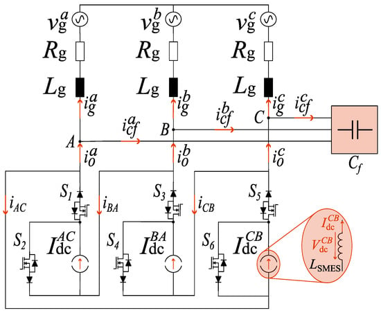
Figure 1.
Delta-type current source converter structure.
The following constraints must always be satisfied in a D-CSC to safely drive the branch switches:
- A conduction path for the DCs of each branch must always be guaranteed, meaning that at least one of the two switches of each branch must be in the on state at all times. This constraint is enforced through the use of overlap times between the on-going and off-going switches in each branch.
- The output phase terminals of the D-CSC must never be shorted to avoid damaging the output filter capacitor bank.
The second constraint is always satisfied when using switches with series diodes because the diodes inherently block the conduction of reverse currents when shorting the output terminals. However, particular attention must be given when using hybrid switches because these allow the current to flow in both directions. This issue can be addressed by appropriately setting the overlap times, e.g., by implementing the four-step commutation method proposed in [15] to avoid shorting the converter output terminals (A, B, and C) at any time.
Let us now compare the structure of the proposed D-CSC with that of a traditional CSC-based PCS, which uses a dedicated CSC for integrating each SMES unit [6], as shown in Figure 2. It is directly evident that—for the same number of storage units interfaced with the AC grid—the proposed solution requires one-third of the semiconductors (i.e., switches and reverse-blocking diodes) and, thus, also gate drivers, as well as one-third of the filtering capacitors. Therefore, the novel D-CSC-based PCS offers the possibility to integrate multiple ESSs with a significant reduction in the number of components and, consequently, of the complexity compared to a traditional CSC-based PCS.
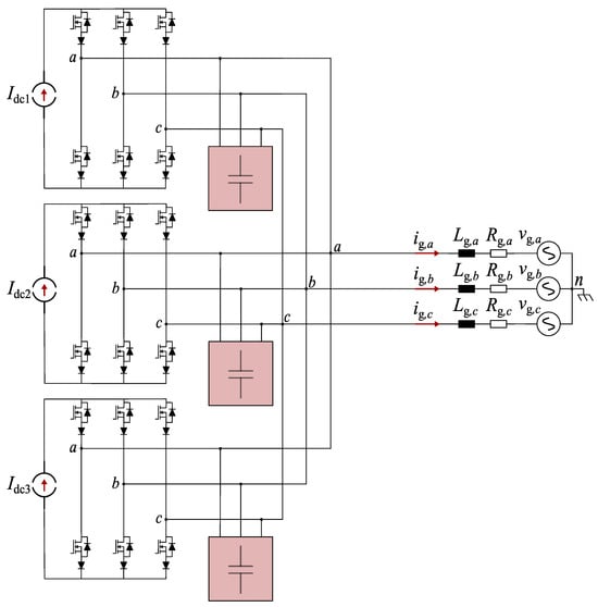
Figure 2.
Traditional CSC-based PCS, using three independent CSCs for interfacing three SMES devices.
3. Control Strategy
The control strategy of the D-CSC is organized into three separate blocks: the grid controller, average current controller, and energy balancing controller. Eventually, the three-phase current control signals synthesized as the sum of the outputs of these three blocks are provided as inputs to the modulator, which provides the gate signal to drive the six switches of the D-CSC. A detailed analysis of the control strategy blocks is presented in the following with the aid of the block diagrams shown in Figure 3 and Figure 4.
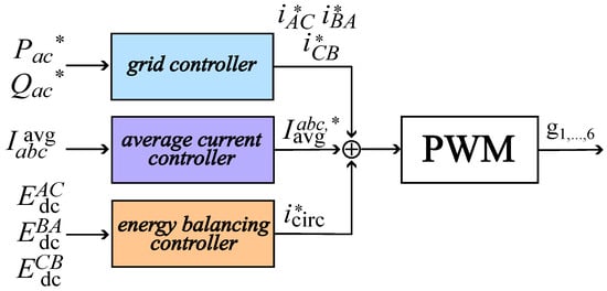
Figure 3.
D-CSC control strategy.
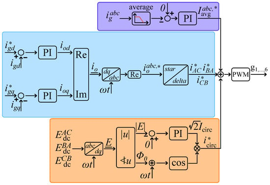
Figure 4.
Complete block diagram of D-CSC control strategy.
3.1. Grid Controller
The grid controller ensures the exchange of the desired active and reactive power and with the grid by properly defining the reference delta currents , and .
The active and reactive power exchange can be expressed in the dq rotating reference frame by applying the Park transformation to the three-phase line-to-ground grid voltages and currents, as follows [16]:
where , , , and are the d and q axis grid voltages and currents, respectively. By locking the phase of the line-to-ground grid voltage through a phase-locked loop (PLL) and fixing , the following is obtained:
Therefore, the decoupled control of and is achieved by regulating and . In the following, a mathematical analysis aimed at deriving the relationship between the grid currents and converter-generated delta currents is provided.
Space vector of the three converter output currents , , and with respect to a stationary reference frame of coordinates is expressed as follows:
where we have the following:
- is the space vector of the three-phase grid currents , , and
- is the space vector of the three-phase capacitor currents , , and .
The output capacitive filter is sized to provide a low-impedance path for the current harmonic components at the switching frequency. On the other hand, at the grid frequency, the impedance of these capacitors is much higher than the grid impedance. Hence, it follows that, because , the current absorbed by the capacitive filter can be neglected. Therefore, considering , the tuning of the grid controller can be performed as in [17].
Applying the inverse Park transformation to yields three current control signals , and . However, these currents are in reference to the grid side of the D-CSC, while the inverter modulation should synthesize the reference currents related to the delta-connected side where the six power switches are actually connected. Therefore, an additional step is necessary to transform into the delta-side current control signals , , and . Supposing that these currents are balanced, their relationship is given by the following:
3.2. Average Current Controller
In the presence of energetic imbalances between the three ESSs caused by different operating conditions, temperature drifts, manufacturing tolerances, aging characteristics, and other factors, undesired average grid current components arise. In particular, the amplitude of these average currents directly depends on the energy imbalance.
As an example, let us address the issue in reference to the target case study of this work: the integration of three SMES devices within the power grid of a marine vessel. Currents , , and are directly related to energy stored in the SMES coils. For example, if the latter have the same inductance but store different amounts of energy, the three constant currents , , and , are also different. These latter currents also represent the peak amplitudes of the three branch currents , , and , respectively, which have a value of either zero or , , and , depending on the state of the six switches of the D-CSC. As a result, in the presence of an energetic imbalance between the three storage units, the branch currents span from zero to three peak values, i.e., , and , which are different, thus resulting in three branch currents with different averages. Hence, three average components arise in , , and to enforce Kirchhoff’s current law at the converter phase terminals, . On the other hand, when the amounts of energy stored by the three SMES units are equal, then the three branch currents , and have equal peak amplitudes and average values, and no average current components arise in the grid currents.
Therefore, a specific control loop should be set up to eliminate the average grid currents by generating three current control signals, denoted as .
3.3. Energy Balancing Controller
The task of the energy balancing controller is to compensate for the energy imbalances arising between the three ESSs, without affecting the external power exchanged by the D-CSC with the grid. This requires enforcing the circulation of an additional zero-sequence current component, , which only flows within the delta-connected side of the converter.
Locking the phase of the grid voltage with a PLL, the fundamental harmonic components of the line-to-line voltages applied on the three branches of the D-CSC are given by the following:
where V is the RMS line-to-line voltage of each branch of the converter at its three output terminals A, B, and C. The zero-sequence circulating current component is expressed as follows:
where and are the peak amplitude and phase of the circulating current component, respectively. The power, , exchanged between the three ESSs, can be computed for branch , , and as follows:
It can easily be noticed that because , , hence, proving that the presence of does not affect the power exchange with the grid.
However, each term of (7) can be individually non-zero and represents the active power flowing from the ESS of each branch toward the other energy sources. This power flow can be controlled by appropriately setting the parameters and , with the purpose of equalizing the amounts of energy stored in the three ESSs. In particular, is related to the amount of power to be exchanged, while determines the direction of this power exchange, i.e., which source (or sources) must be charged and which must be discharged.
To implement a closed-loop energy equalization strategy, the following control algorithm was defined. The overall control scheme is reported in Figure 4. First, energy space vector should be computed by applying the Park transformation to the energy values, , , and , stored in the three ESSs, as follows [18]:
In this way, amplitude of is directly related to the amount of energy imbalance and only reaches zero when . Therefore, a simple PI regulator can be adopted to determine according to the error signal, i.e., . In addition, the power flow direction is provided by setting phase of equal to the phase of .
For the sake of clarification, let us provide a simple example: let us suppose that the amounts of energy , , and , stored by the three ESSs are different, as in Figure 5. In particular, , where the amplitude of indicates the amount of energy imbalance, while phase indicates the branch with the greatest charge. Vector is in the region delimited by vectors and , and is specifically closer to branch . This means that is the branch with the greatest charge, followed by . Thus, the phase of circulating current can be assigned by evaluating the phase of . In this way, combining (5) with (6) and (7) yields the power exchanged between the ESSs.
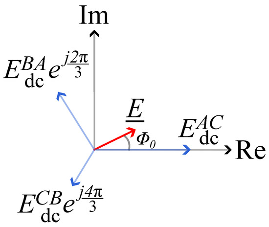
Figure 5.
Energy space vector example.
It must be highlighted that equalizing the amounts of energy stored by the three SMES devices also results in the elimination of the average grid current components, therefore achieving the same objective as the average current controller and making the action of this latter control loop unnecessary when the amounts of energy stored by the three ESSs are equal. Nevertheless, because the energy balancing control loop is slower than the average current control loop, using the latter makes it possible to operate the converter even if the amounts of energy stored by the ESSs are different. In other words, thanks to the average current controller, the D-CSC can exchange power with the grid while the energy balancing controller slowly brings the amounts of energy stored by the three SMES units to the same value. On the other hand, rather than equalizing the amounts of energy stored by the ESSs, the energy balancing controller might be tuned to maintain different energy values. In that case, the average current controller is always active and effectively enables an exchange of power with the grid by erasing the grid current average components.
4. Simulation Case Study
This section discusses the results of a simulation used to test the effectiveness of using the D-CSC to integrate three SMES devices into the electrical grid of a ship. Moreover, the results of a comparative analysis between the proposed D-CSC (Figure 1) and a traditional (Figure 2) CSC-based PCS are also presented. These analysis results highlight the better performances of the proposed D-CSC, in terms of efficiency, THD of the grid currents and overall cost reduction.
Let us consider three SMES units with a rated capacity of and inductance equal to each. Therefore, each SMES was modeled with a constant current source, , of . Furthermore, the D-CSC rated power, , was equal to . Nevertheless, the operation of the D-CSC was tested considering three different active power setpoints, (, and ) to show that the balancing controller action could prevent a significant discharge of the three SMES units. The reactive power set-point, , was instead kept at zero. A comprehensive set of simulation parameters is provided in Table 1. It is worth highlighting that, to reduce the joule losses related to the circulation of , the energy balancing controller activates only if the energetic imbalance overcomes a pre-defined arbitrary threshold, thus forcing the circulation of only if .

Table 1.
Simulation parameters.
Several different simulation case studies are presented to show the converter operation under both balanced and unbalanced energetic operating conditions.
4.1. Balanced Operating Conditions
In this scenario, the simulation starts with three SMES devices storing exactly the same amounts of energy, equal to , which results in . Moreover, the inductance values of the three SMES coils are fixed at the rated value of , hence neglecting deviations due to manufacturing tolerances.
Figure 6a shows the active power exchange between the D-CSC and the grid, demonstrating the capability of the grid controller to track the active power setpoint, . The three grid currents, , , and , are displayed in Figure 6c. It can be observed that—in the absence of energy imbalances among the three ESSs—the three-phase currents are symmetrical, and no average grid current component is present. Indeed, the total harmonic distortion is equal to 0.98%. The graph of Figure 6d depicts the amounts of energy stored by the three SMES devices over time, which are directly linked to the SMES currents depicted in Figure 6b. It is noteworthy that even when the active power output of the converter is zero (e.g., for and ), the amounts of energy stored by the SMESs decreases. This is caused by the conduction losses resulting from the SMES currents flowing in switches , , and .
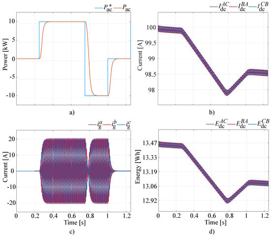
Figure 6.
Balanced operating conditions: (a) active power output, (b) SMES currents, (c) grid currents, and (d) SMES energies.
4.2. Unbalanced Operating Conditions
The operation of the D-CSC with three SMESs storing different initial amounts of energy was tested considering three separate cases.
- In the first scenario, a 20% inductance tolerance deviation was set: , and were equal to , and , respectively. Additionally, the initial SMES currents were equal to each other, i.e., .
- In the second scenario, the initial SMES currents varied by 10% between the three SMES units, with , and . Moreover, the SMES coils inductances are equal to each other, i.e., .
- The third scenario considered both different inductance values and different initial currents, with , and again equal to , and , respectively; and , and .
The active power reference profile used for these simulations followed the same pattern as that shown in Figure 6a, repeated over time. The activation of both the average current and energy balancing controllers occurred at . This delay was purposely introduced to highlight the effect of the energetic imbalances between the SMES units on the grid currents. Moreover, the grid connector closed at .
The simulation results for the first scenario are summarized in Figure 7. In this case, the amounts of energy stored by the SMES units were , and . The SMES currents started from the same value (i.e., 100 A): therefore, the average values of the three branch currents, , , and were equal, and the grid currents were symmetric, i.e., no average current component appeared. The action of the energy balancing controller is depicted by Figure 7d), where it is possible to observe that the amounts of energy stored by the three SMES equalized after almost 4 s. However, the three SMES currents, , , and became different. This was a consequence of the action of the energy balancing controller because the only way to balance the amounts of energy stored by the three coils with different inductance values was to force the circulation of three different SMES currents. Nevertheless, even if these currents were different, the combined action of the average current controller ensured that there was no evident effect on the three grid currents, , , and , as seen in Figure 7c.
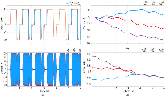
Figure 7.
Unbalanced operating conditions with different SMES coil inductances: (a) active power output, (b) SMES currents, (c) grid currents, and (d) SMES energy values.
The results for the second simulation scenario, in which the inductances of the SMES coils were all equal but the initial currents varied by 10% of the rated value, are depicted in Figure 8. In this case, , , and . In contrast to the previous scenario, it is possible to observe that because , , and are different from each other, average current offsets of , , and appear. As seen in Figure 8c, the average currents arose even when the grid connector was closed and zero active power was exchanged with the grid. Nevertheless, as shown in Figure 8c, after the activation of the average current controller at , these undesired current components are quickly disappeared, which guaranteed the proper grid operation. Moreover, just as in the previous scenario, under these conditions, the amounts of energy stored by the three ESSs, as well as their respective currents, became equal, as highlighted in Figure 8d,b.
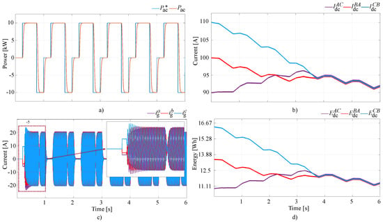
Figure 8.
Unbalanced operating conditions with different SMES currents: (a) active power output, (b) SMES currents, (c) grid currents, and (d) SMES energy values.
Finally, the results for the third unbalanced operating scenario were a mixture of the previous results. As seen in Figure 9a,c because , , and had different values at the start, average grid current components arose, as shown in Figure 8c. Again, they quickly disappeared as a result of the average current control loop. Moreover, just as in the first unbalanced scenario, because the three SMES coils had different inductances, the only way for the energy balancing controller to equalize the amounts of energy stored by the ESSs was to force the circulation of different SMES currents. In fact, as highlighted in Figure 9b, currents , , and were always different from each other. Nevertheless, the presence of these imbalances did not significantly affect the operation of the D-CSC, which was able to exchange power with the grid under every operating condition.
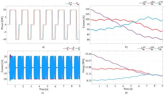
Figure 9.
Unbalanced operating conditions with different inductances and currents for the SMES coils: (a) active power output, (b) SMES currents, (c) grid currents, and (d) SMES energy values.
Finally, it is worth noting that in the third unbalanced operating scenario, more time was required for the equalization of the amounts of energy stored by the SMES units, compared to the other two unbalanced operation cases, because the energy difference between the ESSs was greater.
4.3. Proposed PCS Performance against Traditional Solution
The topology of a traditional CSC-based PCS is shown in Figure 2. It consists of three independent CSCs individually connected to the AC grid through a capacitive filter, as proposed in [6]. Each CSC integrates a single SMES on the DC side. A model of this PCS to assess its performances against those of the proposed D-CSC under the following assumptions.
- The three SMES units were represented as constant current sources, i.e., , , and , as represented in Figure 2. This avoided changes in the DC-side currents and, therefore, losses due to the charging/discharging of the storage devices. Balanced operating conditions were assumed, i.e., . Moreover, for the D-CSC , thus using the same equal constant current sources for both converter solutions.
- The amounts of capacitive energy stored by the capacitive filters were equal for both PCSs. Therefore, because the operating voltages of the filters were the same in both cases, this implied that each capacitor of the traditional PCS had 1/3 the capacitance of the capacitors employed for the D-CSC. In particular, for the traditional PCS, while for the PCS based on the D-CSC.
- The same grid controller and modulation strategy were employed for both PCS solutions, using equal tuning parameters.
- Both the efficiency and THD were evaluated considering the unitary modulation index as a maximum limit. This choice implied that the maximum apparent power exchanged with the grid was . Hence, the evaluation of both quantities was performed within this capability region for both PCSs solutions.
The semiconductor sizing requirements should be addressed first because these are of key importance for a fair comparison of the two PCSs. Consider the D-CSC structure presented in Figure 1, with a specific focus on branch AC. The SMES unit associated with this branch is either connected to the converter output terminals through switch S1, or bypassed through switch S2. Therefore, each switch must be capable of handling the full DC of each SMES in the case that where the D-CSC is suddenly disconnected from the grid. Indeed, when this disconnection occurs, the DC-side energy sources are short circuited by closing S2, S4, and S6. As a consequence, for the D-CSC, the RMS current ratings of the semiconductors (i.e., active switches and series reverse-blocking diodes) correspond to the full DC-side currents, i.e., , , and .
On the other hand, for the traditional PCS based on multiple CSCs shown in Figure 2, in a case of a grid disconnection, flow paths for the DC-side currents are provided by short-circuiting the storage devices through the CSCs switches. However, in contrast to the previous case, implementing a suitable control logic for the converter’s phase-leg can alternatively short-circuit the energy source for 1/3 of the grid fundamental period. Therefore, in contrast to the D-CSC, for this PCS topology, this operating condition does not represent the worst case to be analyzed when determining the rated currents of the semiconductors. Indeed, the worst case scenario occurs during the normal operation of the converters, in which, to adopt a scheme such as space vector modulation or sinusoidal PWM, the RMS currents of the active switches and series reverse-blocking diodes are equal to , independently from the modulation index.
The same considerations also hold for the reverse-blocking diodes because, as a result of the series connection with the MOSFETs, they are subject to the same currents. Regarding instead the semiconductors’ voltage ratings, they must be capable of withstanding the full peak AC phase-to-phase voltage, for both PCS solutions.
Hence, because the semiconductors’ current ratings with the CSC-based traditional PCS are lower than those of the D-CSC-based PCS (i.e., ), with equal voltage rating, the semiconductors’ power ratings are also lower. Thus, supposing that the semiconductor’s cost is directly related to their sizing power, the cost of the single semiconductor component for the former PCS solution is also times lower. Nevertheless, considering the whole PCS, the D-CSC requires a third of the semiconductors. Thus, in conclusion, the overall semiconductors cost for the traditional CSC-based PCS is (i.e., roughly 73%) times higher than that of the proposed D-CSC-based PCS. Moreover, the cost reduces further since the D-CSC also requires a third of the gate drivers.
Considering the previous requirements, MOSFETs and series diodes were chosen based on the market availability. In addition, the choice of the specific semiconductors employed for this comparison was performed by prioritizing the use of devices from the same manufacturer and production series, to avoid major differences in their realization, possibly providing efficiency advantages to one solution over the other. Indeed, the chosen SiC semiconductors were MOSFETs C3M0015065K and C3M0025065L for the D-CSC and classic CSC, respectively, and series diodes C6D50065D1 for both PCSs. All devices were produced by Wolfspeed, and their main parameters are reported in Table 2. Regarding the series diodes, three components in parallel were used for the D-CSC, in order to match the diode current requirement. In contrast, for each of the three traditional CSCs two diodes were connected in parallel.

Table 2.
Semiconductor s parameters.
Concerning the efficiency comparison, the results of the analysis are shown in Figure 10. It is evident that the D-CSC showed better performances over the entire operating range of the PCS. This was mostly related to the lower number of semiconductors compared to the traditional CSC-based PCS, which led to significant reductions in the converter losses.
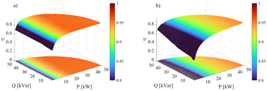
Figure 10.
Efficiency maps: (a) proposed D-CSC and (b) traditional PCS consisting of three CSCs.
Considering the THD of the grid currents, i.e., , and , the results of the comparison are shown in Figure 11. In this case also, the D-CSC performed better than its respective traditional CSC counterpart, injecting high-quality currents into the grid, achieving the same overall capacity (stored energy) of the filter capacitor banks. Indeed, while for the traditional CSC-based PCS, the current THD was higher than 5% over most of the operating range, for the D-CSC, the THD varied between 1% and 3%, depending on the specific setpoint. This was due to the fact that each of the three CSCs composing the traditional PCS operated at 1/3 of the apparent power setpoint of the proposed D-CSC. As a consequence, for the same output apparent power, the modulation index of each CSC was also lower, and this negatively affected the THD of the output currents.
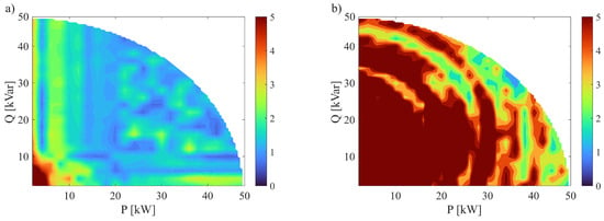
Figure 11.
Percentage THD maps: (a) proposed D-CSC and (b) traditional PCS consisting of three CSCs.
Hence, achieving the same output current THD as the proposed D-CSC solution would require a higher capacity for the output filter in traditional PCS solutions. However, a higher capacity would also imply a greater amount of stored energy, because the voltages applied to the filter capacitors would be the same in both cases. Therefore, because the cost of capacitors is proportional to their energetic rating, just as with the semiconductors, for the output filters, the overall cost of the CSC-based PCS would be higher than that of the novel D-CSC-based PCS if the same THD is required.
5. Conclusions
This paper presents a novel D-CSC that makes it possible to interface three independent ESSs with the power grid of a marine vessel. While the other CSC-based solutions found in the literature only allow the integration of a single ESS, the proposed D-CSC makes it possible to interface three independent storage units with the power grid, using the same number of components (i.e., power semiconductors) as a traditional CSC. Thus, if three ESSs need to be interconnected with the AC grid, the proposed solution allows a single D-CSC to be employed rather than three separate CSCs, significantly reducing the number of semiconductors compared to traditional solutions and thus considerably reducing the cost of the PCS.
In addition, this work introduces an innovative energy management strategy for controlling the D-CSC, which makes it possible to compensate for any energetic imbalance arising between the three energy sources. Indeed, these imbalances may occur due to manufacturing tolerances and different aging conditions for the converter components and ESSs, as well as temperature drifts, different operating set-points, inverter modulation errors, and other factors. As a result, in contrast to other CSC solutions proposed in the literature, even when the amounts of energy stored in the ESS are unequal, the D-CSC can properly operate and ensure the injection of high-quality symmetrical currents into the grid. This capability enables the use of the D-CSC for integrating both first and second-life storage devices or even ESSs with different rated characteristics, e.g., those produced by different manufacturers, thus significantly improving the flexibility of the PCS with respect to traditional CSC solutions.
Finally, the performances of the proposed D-CSC were compared with those of a traditional PCS, based on three independent CSCs, each one integrating a single SMES on the DC side. This comparative analysis highlighted the better performances of the proposed converter solution over the entire operating range of the PCS, both in terms of the efficiency and THD of the grid currents.
In conclusion, with reference to a traditional PCS solution based on three independent CSCs, the advantages of the proposed D-CSC are as follows:
- Because of its innovative topology, the D-CSC is able to interface with three independent ESS units. On the other hand, using the same number of components, a traditional CSC is only capable of integrating with one storage device. In other words, the integration of three energy storage devices is performed using one D-CSC instead of requiring three CSCs, thus reducing the number of components by three times (i.e., the power semiconductors and filter capacitors).
- Thanks to the innovative control strategy that was specifically developed for the D-CSC, the proposed converter solution ensures proper grid operation even if the amounts of energy stored by the three storage devices are unequal (e.g., because of manufacturing differences and different aging characteristics and tolerances). In addition, the adopted control strategy is capable of equalizing the amounts of energy stored by the ESSs without affecting the operation with the grid, hence making it possible to integrate both first and second-life storage devices.
- Compared with the aforementioned traditional PCS, the D-CSC provides better performances, in terms of the efficiency and THD of the output currents, over the entire operating range.
- Considering the lower number and power rating of the semiconductor components, a significant cost reduction is also made possible through the adoption of the proposed D-CSC.
Author Contributions
Conceptualization, M.B. and R.S.; methodology, M.B., D.D.S. and R.S.; software, D.D.S. and R.S.; validation, M.B., D.D.S. and R.S.; formal analysis, R.S.; investigation, R.S.; resources, L.P.; data curation, M.B., D.D.S., L.P. and R.S.; writing—original draft preparation, R.S.; writing—review and editing, M.B., D.D.S., L.P. and R.S.; visualization, R.S. and L.P.; supervision, L.P.; project administration, L.P.; and funding acquisition, L.P. All authors have read and agreed to the published version of the manuscript.
Funding
This research was funded by the framework of the V-Access project by the European Union under grant agreement ID 101096831.
Data Availability Statement
Data are contained within the article.
Conflicts of Interest
The authors declare no conflicts of interest.
References
- Abdelnabi, H.; Couture, D.T.; Elguindy, A.; Epp, B.; Fichaux, N.; Gibb, D.; Joubert, F.; Ledanois, N.; Levin, R.; Murdock, H.E.; et al. Renewables 2022 Global Status Report-Renewable Energy Policy Network for the 21st Century. Rep. No. REN21. 2022. Available online: https://www.ren21.net/reports/global-status-report/ (accessed on 22 February 2024).
- ENTSO-E. ENTSO-E Annual Report. 2022. Available online: https://www.entsoe.eu/publications/general-publications/annual-report/ (accessed on 22 February 2024).
- Adetokun, B.B.; Oghorada, O.; Abubakar, S.J.A. Superconducting magnetic energy storage systems: Prospects and challenges for renewable energy applications. J. Energy Storage 2022, 55, 105663. [Google Scholar] [CrossRef]
- de Jesús Hernández Hernández, R.; Cárdenas, V.; Espinosa-Pérez, G. Development of a current source inverter for energy storage systems. In Proceedings of the 2016 13th International Conference on Power Electronics (CIEP), Guanajuato, Mexico, 20–23 June 2016; pp. 283–288. [Google Scholar]
- Imaie, K.; Tsukamoto, O.; Nagai, Y. Control strategies for multiple parallel current-source converters of SMES system. IEEE Trans. Power Electron. 2000, 15, 377–385. [Google Scholar] [CrossRef]
- Wang, Z.; Jiang, L.; Zou, Z.; Cheng, M. Operation of SMES for the Current Source Inverter Fed Distributed Power System Under Islanding Mode. IEEE Trans. Appl. Supercond. 2013, 23, 5700404. [Google Scholar] [CrossRef]
- Alafnan, H.; Zhang, M.; Yuan, W.; Zhu, J.; Li, J.; Elshiekh, M.; Li, X. Stability Improvement of DC Power Systems in an All-Electric Ship Using Hybrid SMES/Battery. IEEE Trans. Appl. Supercond. 2018, 28, 5700306. [Google Scholar] [CrossRef]
- Elmorshedy, M.; Amin, M.M.; El-Sousy, F.F.M.; Mohammed, O.A. DC-bus voltage control of MPPT-based wind generation system using hybrid BESS-SMES system for pulse loads in ship power applications. In Proceedings of the IEEE Applied Power Electronics Conference and Exposition (APEC) IEEE, Phoenix, AZ, USA, 14–17 June 2021. [Google Scholar]
- Zheng, Z.; Chen, X.; Hu, W.; Wang, Y.; Zong, Y.; Huang, C.; Ni, F. Dual Model Predictive Controlled Hybrid Energy Storage System for Naval DC Microgrids. IEEE Trans. Transp. Electrif. 2023, 9, 156–168. [Google Scholar] [CrossRef]
- Monteiro, V.; Exposto, B.; Pinto, J.G.; Sepúlveda, M.J.; Meléndez, A.A.N.; Afonso, J.L. Three-phase three-level current-source converter for EVs fast battery charging systems. In Proceedings of the 2015 IEEE International Conference on Industrial Technology (ICIT), Seville, Spain, 17–19 March 2015; pp. 1401–1406. [Google Scholar]
- Klumpner, C. A New Single-Stage Current Source Inverter for Photovoltaic and Fuel Cell Applications using Reverse Blocking IGBTs. In Proceedings of the 2007 IEEE Power Electronics Specialists Conference, Orlando, FL, USA, 17–21 June 2007; pp. 1683–1689. [Google Scholar]
- Cossutta, P.; Aguirre, M.P.; Cao, A.; Raffo, S.; Valla, M.I. Single-Stage Fuel Cell to Grid Interface With Multilevel Current-Source Inverters. IEEE Trans. Ind. Electron. 2015, 62, 5256–5264. [Google Scholar] [CrossRef]
- Darwish, A.; Aggidis, G.A. A Review on Power Electronic Topologies and Control for Wave Energy Converters. Energies 2022, 15, 9174. [Google Scholar] [CrossRef]
- Huber, J.; Kolar, J.W. Monolithic Bidirectional Power Transistors. IEEE Power Electron. Mag. 2023, 10, 28–38. [Google Scholar] [CrossRef]
- Torres, R.A.; Dai, H.; Lee, W.; Sarlioglu, B.; Jahns, T. Current-Source Inverter Integrated Motor Drives Using Dual-Gate Four-Quadrant Wide-Bandgap Power Switches. IEEE Trans. Ind. Appl. 2021, 57, 5183–5198. [Google Scholar] [CrossRef]
- Akagi, H.; Kanazawa, Y.; Fujita, K.; Nabae, A. Generalized theory of the instantaneous reactive power and its application. Trans. Inst. Electr. Eng. Jpn. 1983, 103.7, 483–490. [Google Scholar] [CrossRef]
- Dash, P.P.; Kazerani, M. A multilevel current-source inverter based grid-connected photovoltaic system. In Proceedings of the 2011 North American Power Symposium, Boston, MA, USA, 4–6 August 2011; pp. 1–6. [Google Scholar]
- Brando, G.; Dannier, A.; Spina, I.; Tricoli, P. Integrated BMS-MMC Balancing Technique Highlighted by a Novel Space-Vector Based Approach for BEVs Application. Energies 2017, 10, 1628. [Google Scholar] [CrossRef]
Disclaimer/Publisher’s Note: The statements, opinions and data contained in all publications are solely those of the individual author(s) and contributor(s) and not of MDPI and/or the editor(s). MDPI and/or the editor(s) disclaim responsibility for any injury to people or property resulting from any ideas, methods, instructions or products referred to in the content. |
© 2024 by the authors. Licensee MDPI, Basel, Switzerland. This article is an open access article distributed under the terms and conditions of the Creative Commons Attribution (CC BY) license (https://creativecommons.org/licenses/by/4.0/).