1. Introduction
Valve-controlled hydraulic cylinders (VCCs) are used extensively in various industries, particularly in heavy load-carrying scenarios. VCCs offer numerous advantages, including a high power-to-weight ratio, flexible power transmission, inherent damping qualities, and a good liability. Despite decades of development, VCCs still face a major challenge: valve throttling losses. These losses are mainly from the system’s control and over-center valves [
1]. For instance, control valves account for approximately 29% to 35% of the total energy losses in an excavator equipped with load-sensing functionality [
2,
3]. VCCs require brake throttling valves to operate in more than two quadrants and lack energy recuperation capability under overrunning loads, indirectly amplifying energy losses. The demand for efficient hydraulic systems has become increasingly critical with the growing global energy demand, environmental considerations, and sustainable industrial practices. Therefore, designing hydraulic cylinder systems that deliver comparable performance as VCCs while removing the throttling losses is important. In response to this trend, motor-controlled hydraulic cylinders (MCCs) have emerged as a promising technology, offering a more efficient alternative to VCCs.
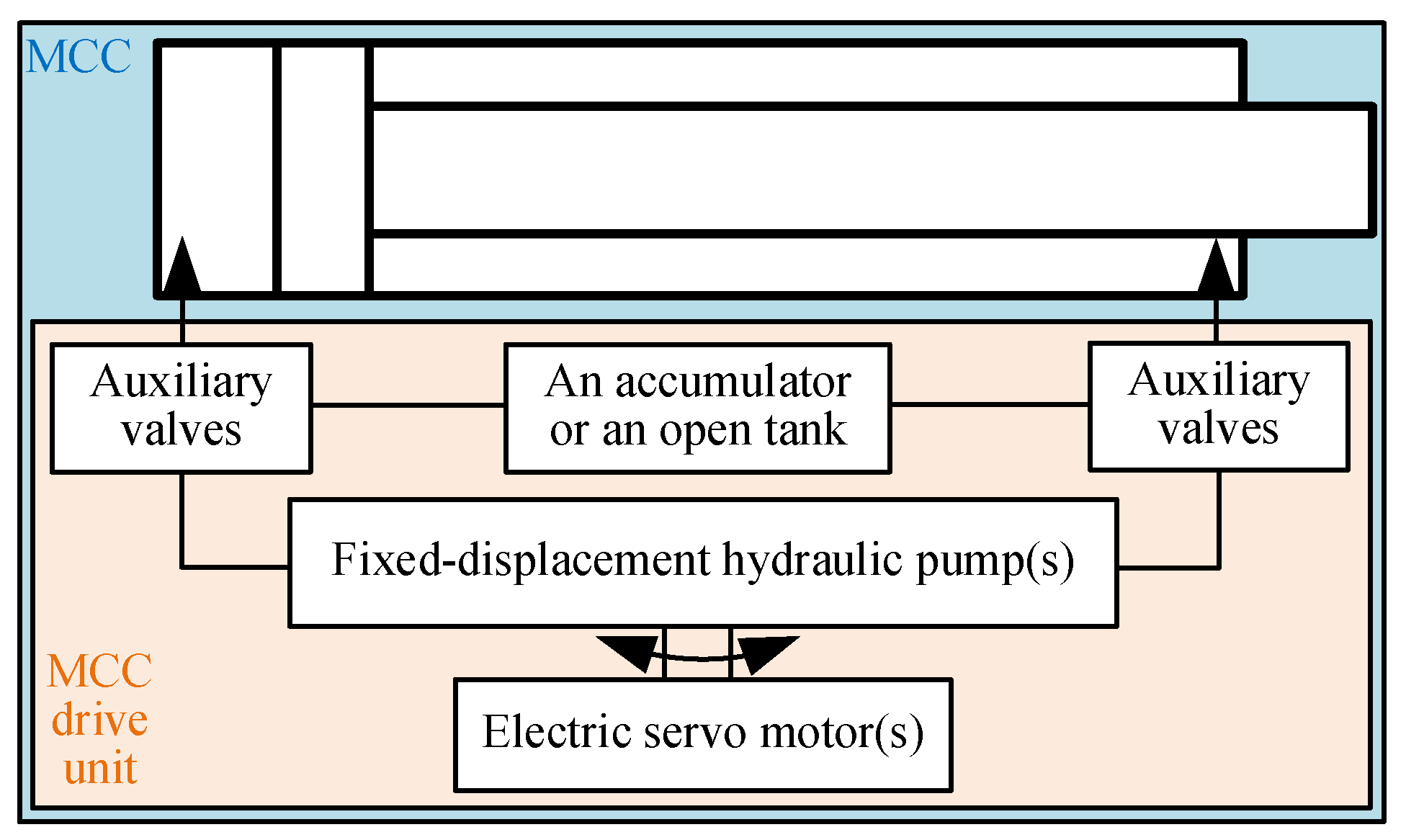
Figure 1 provides the general structure of an MCC. An MCC incorporates an electric motor(s) and hydraulic pump(s), an accumulator or an open tank, several auxiliary valves, and a differential hydraulic cylinder. The hydraulic cylinder is directly connected to one or two fixed-displacement hydraulic pumps driven by electric servo motors. Therefore, the cylinder motion is controlled by the electric servo motor’s angular velocity. The auxiliary valves compensate for the differential flow rate, enable load-holding functionality according to different MCC architectures, or avoid cavitation. MCCs can be classified into four groups based on the number of electric servo motors and fixed-displacement hydraulic pumps utilized: one-motor-one-pump (1M1P), one-motor-two-pumps (1M2P), one-motor-three-pumps (1M3P), and two-motors-two-pumps (2M2P) MCCs [
4]. In contrast to VCCs, the absence of valve throttling in an MCC greatly improves the system’s energy efficiency. For example, a single-boom crane driven by a 1M1P MCC has been shown to consume 62% less energy than one driven by a VCC [
5]. A study of implementing six 1M1P MCCs on an excavator was conducted, as described in [
6]. Experimental results demonstrated that the MCCs consumed 47.8% less energy than the valve-controlled counterparts in a given working cycle. Furthermore, an excavator powered by three 1M2P MCCs was shown to achieve a system efficiency of 73.3% in a given working cycle in simulations [
7]. This efficiency is significantly higher than that of the same excavator driven by three VCCs.
It was found that a single-boom crane driven by a 1M1P MCC achieved a 75% shorter settling time, 61% less overshoot, and 66% lower position tracking error compared to a single-boom crane driven by a VCC in a given working cycle [
8]. The MCC’s advantages have led to increased interest in MCCs from the industry. Several commercial MCC products have become available in recent years, for example, from Parker Hannifin [
9], Bosch Rexroth [
10], and Thomson [
11].
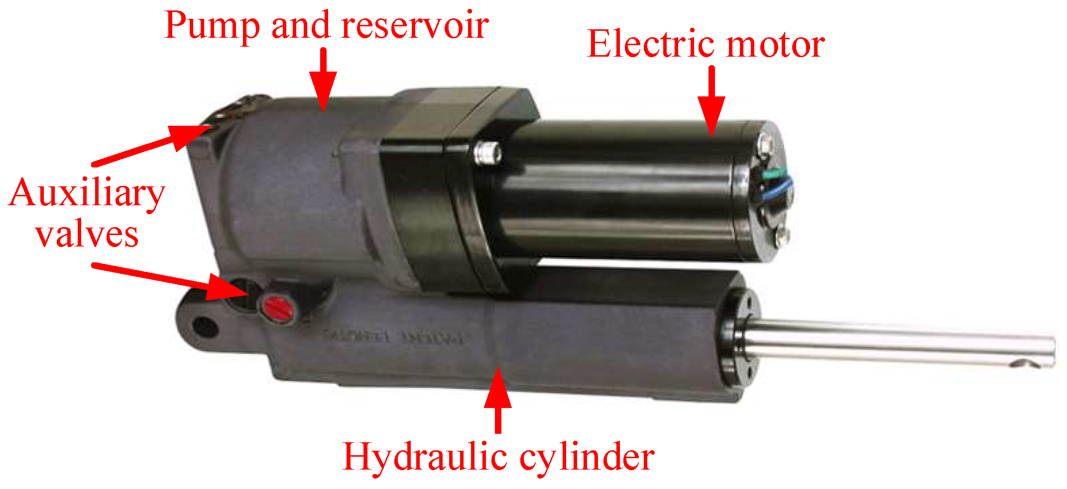
It is worth noting that most research and commercial products related to MCCs primarily focus on the compact installation approach [
12]. In this approach, all components are mounted as an integrated unit, as depicted in
Figure 2. This integrated design offers advantages in terms of saving total occupied space and simplified installation. However, it has been identified that MCCs in the compact installation approach may not be suitable for large-scale knuckle boom cranes for various reasons [
12]. In such cases, MCCs utilizing a remote installation approach become necessary, such as the MCC drive unit shown in
Figure 1 remotely installed in the crane hydraulic machine room and connected to the cylinder with pipelines [
12].
Nevertheless, achieving a passive load-holding function in MCCs with the remote installation approach is challenging. The load-holding function in four-quadrant operation is enforced by legislation when a cylinder is used in lifting applications characterized by overrunning external loads, such as cranes, trailer lifts, and scissors tables. Additionally, activating the load-holding function during a standstill command is essential for energy savings and precise position control. Counterbalance valves, a well-established and proven technology commonly employed in VCCs, can provide load-holding functions in MCCs in general and, in particular, during a loss of power supply or hose rupture [
13,
14]. However, including counterbalance valves in an MCC can decrease the system’s efficiency because of the throttling losses of counterbalance valves, particularly when the load is very low. Moreover, an MCC incorporating counterbalance valves cannot realize four-quadrant operation and energy regeneration because the pilot pressures are too low to open the counterbalance valves in the second and fourth quadrants.
Besides counterbalance valves, two on/off electric valves can be used in MCCs for an active load-holding function without introducing any throttling losses [
7,
15]. While the normally closed on/off electric valves can offer a load-holding function during loss of power supply, implementing load-holding functions during hose ruptures can pose challenges in a remotely installed MCC. A novel load-holding strategy for a 1M1P MCC was presented in [
16]. It incorporates two pilot-operated check valves (POCVs) as load-holding valves. An electric valve connects the pilot line to the cylinder load pressures. This configuration enables the load-holding valves to be opened by hydraulic pressures instead of electric signals. Nevertheless, similar to the concept of using two on/off electric valves, this strategy lacks the capability to provide load-holding functionality in the event of hose ruptures or sudden drops in line pressure.
A 2M2P MCC with a fully passive hydraulically driven load-holding device was introduced in [
17]. In that study, a secondary electric servo motor and a secondary hydraulic pump were incorporated into a 1M1P MCC to manage the differential flow rate and control the minimum cylinder pressure. The load-holding valves were opened by controlling the minimum cylinder pressure over a certain level. This setup provided the desired fully hydraulically driven load-holding function, handling hose ruptures or sudden line pressure drops. However, it is important to note that the 2M2P MCC is less suitable for four-quadrant operation because the secondary servo motor and hydraulic pump cannot contribute to the cylinder’s output power in quadrants II and III [
18]. Therefore, a 1M1P MCC with a fully hydraulically driven passive load-holding function best fits the four-quadrant operation. Nevertheless, further research in this area is currently lacking.
This paper proposes a new 1M1P MCC design that offers a hydraulically driven passive load-holding function to address the gap mentioned above. The proposed design’s functionalities are comprehensively analyzed and validated through simulations.
3. System Modeling
The dynamic system model of the proposed 1M1P MCC is derived based on the experimentally validated system model of a 2M2P MCC utilized in [
18]. The selected off-the-shelf components of the proposed 1M1P MCC are listed in
Table 1. The modeling parameters are from the datasheet of these components.
M is modeled by a second-order transfer function; see Equation (
1). In this equation,
denotes the input signal to the motor from the position controller, and
represents the resulting motor shaft velocity. The motor dynamics are characterized by a natural frequency
of 23.8 Hz and a damping ratio
of 0.73. According to the datasheet, the energy efficiency (
) of M is 95%. For the purposes of this paper, saturation limits for M are not reached and are thus disregarded.
P is rigidly connected to M and rotates at the same angular velocity
. The pump flow rate
is modeled using Equation (
2), with a displacement of
cc/rev. The modeling of leakages
and
in P uses Equations (
3) and (
4), respectively.
represents the pressure difference between the left side of the pump and the accumulator. In contrast,
represents the pressure difference between the right side of the pump and the accumulator. The pump leakage coefficient
is
L/min/bar. Therefore, the pump flow rates on the right side (
) and left side (
) are expressed in Equations (
5) and (
6), respectively. Experimental data in [
18] indicate that the leakage between the two sides of the cylinder is insignificant, and therefore, it is neglected.
The theoretical torque
of P is derived via Equation (
7). The torque loss
of P is derived by scaling a reference torque loss
from steady-state experimental data of a reference axial-piston unit with displacement equal to
= 75 cc/rev [
19].
is a function of
and
. The same method was also used in [
16]. The scaling factor
and torque loss
are calculated via Equations (
8) and (
9), respectively.
The hydraulic system is simulated using an approach where the effective bulk modulus (
) of the fluid in the
i-th hydraulic chamber is determined through a combination of Equations (
10)–(
12).
bar is the hydraulic oil’s bulk modulus.
is the pressure in the
i-th hydraulic chamber.
1 bar is the atmospheric pressure.
1.4 is the air adiabatic constant.
is the
i-th chamber entrapped air bulk modulus.
0.01 is the entrapped air relative volume at atmospheric pressure.
is the entrapped air relative volume in the
i-th chamber. The Greek letter
represents the volume ratio between undissolved gas and oil at atmospheric pressure.
The hydraulic cylinder model comprises three parts: pressure build-up, pressure-force conversion, and cylinder friction. The pressure build-up on the bore side (
) and rod side (
) of the cylinder are represented by Equations (
13) and (
14), respectively. The flow rates going in or out of the cylinder bore and rod sides are denoted by
and
, respectively. The piston position and velocity are represented by
and
, respectively. The bore and rod side areas are denoted by
and
, respectively. The maximum cylinder stroke is
400 mm, the bore side diameter is 63 mm, and the rod side diameter is 45 mm. The cylinder dead volume plus line volume is denoted by
. The pressure-force conversion
is modeled via Equation (
15). The friction between the cylinder and piston is modeled as Stribeck friction; see Equation (
16). The viscous friction coefficient is denoted as
and is equal to 4000 Ns/m. The Coulomb friction force is represented by
and is equal to 75 N. The hyperbolic tangent coefficient is
, which is equal to 250 s/m. The static friction force is
, with a value of 500 N. The static friction time constant is
, with a value of 0.02 m/s. It should be noted that the complexity of cylinder friction can vary, and incorporating factors like the pressure difference (
) may provide a more detailed representation. However, in this study, the pressure levels are similar across experiments. Therefore, the Stribeck friction model is considered adequate.
The modeling approach for the bladder accumulator follows the method proposed in [
20]. According to Equation (
17), the gas pressure
is equivalent to the fluid pressure
when the fluid pressure is greater than the pre-charged gas pressure (
0.96 bar), which, in this paper, is considered to be always true. When the gas pressure changes, the gas volume
is modeled via Equation (
18). The symbol
n represents the adiabatic gas constant. The fluid volume
is calculated as the difference in total accumulator volume
(2.8 L) and gas volume
, as shown in Equation (
19). The fluid pressure build-up
is modeled via Equation (
20). The fluid volume changing rate
is calculated via Equation (
21). The accumulator pressure
is equal to the fluid pressure
.
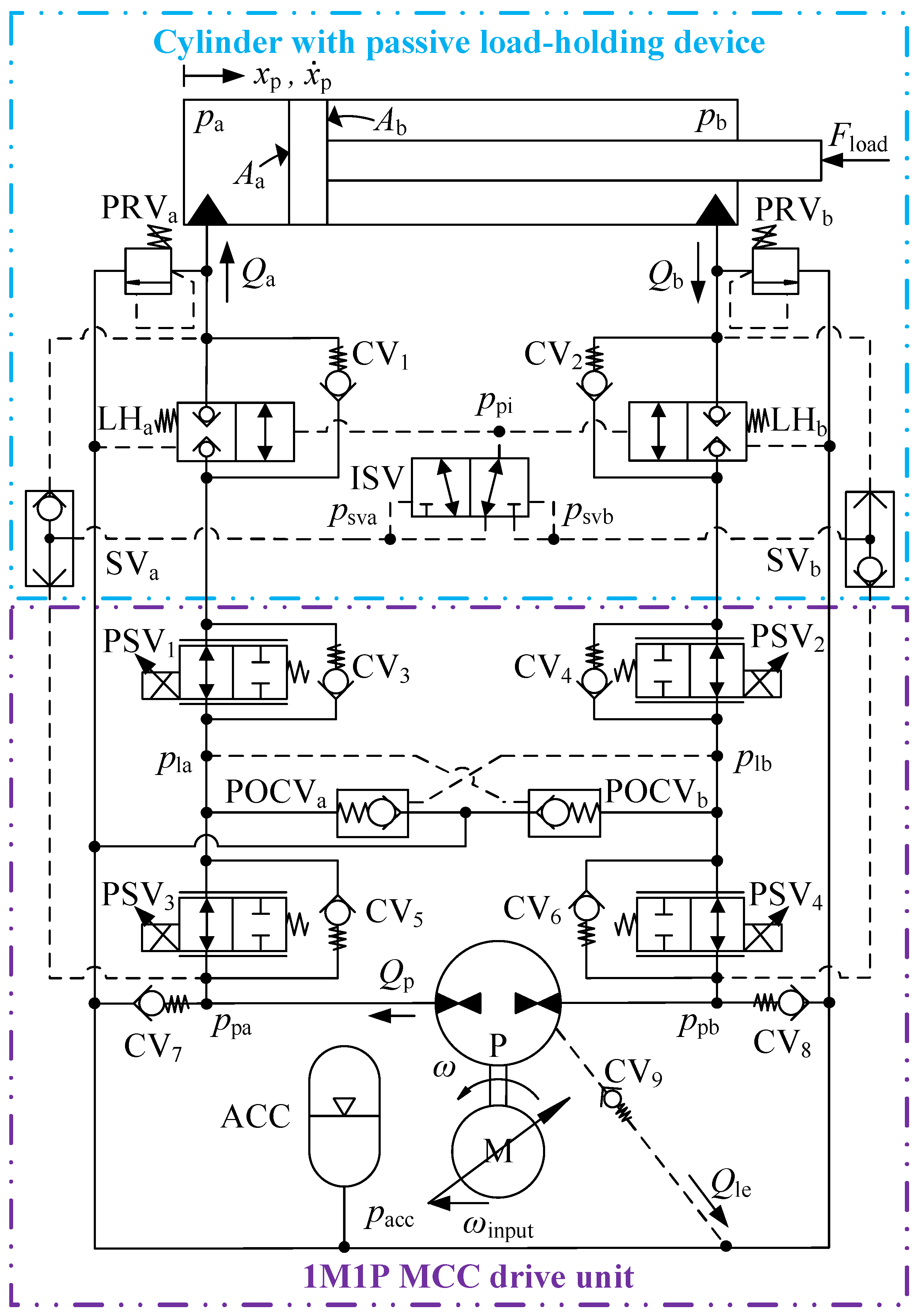
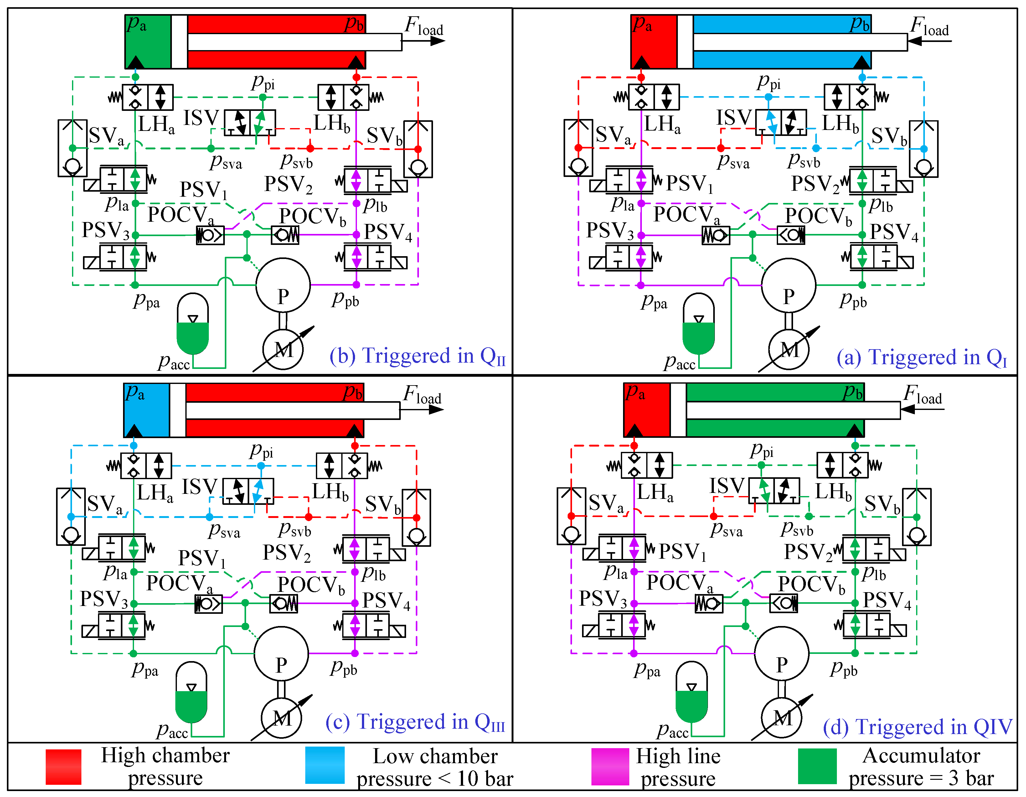
Nine CVs are used in the proposed 1M1P MCC, as shown in
Figure 3. Equation (
22) is used to model the behavior of all these CVs.
represents the pressure drop across the
i-th CV, and
denotes the corresponding flow rate. The same cracking pressure
0.2 bar is used for all CVs, and they all have the same CV flow rate constant of
500 L/min/bar.
Two SVs and an ISV are used in the pilot lines. They are modeled as logic elements. Equation (
23) shows the logic of ISV. Equations (
24) and (
25) show the logic of
and
, respectively.
The modeling approach for the two non-vented, pressure-operated check valves (POCVs) aligns with the method presented in [
16]. The calculation of the flow rates through POCVs, denoted as
, is performed using the orifice equation, Equation (
26).
This equation takes the following properties into account: a pressure differential across the valve
, a valve opening constant
, a dimensionless poppet lift
, a pilot ratio (
), fluid density
, a valve inlet pressure
, and a valve outlet pressure
. The symbol
i represents the
i-th POCV. The dimensionless poppet lift
is computed in two different ways depending on the mode of operation. If the POCV is acting as a regular check valve, it is computed via Equation (
27), and if it is acting as a pilot-operated check valve, it is computed via Equation (
28).
In the equations, represents the pilot pressure, represents the valve cracking pressure, and represents the pressure difference required to fully open the check valve.
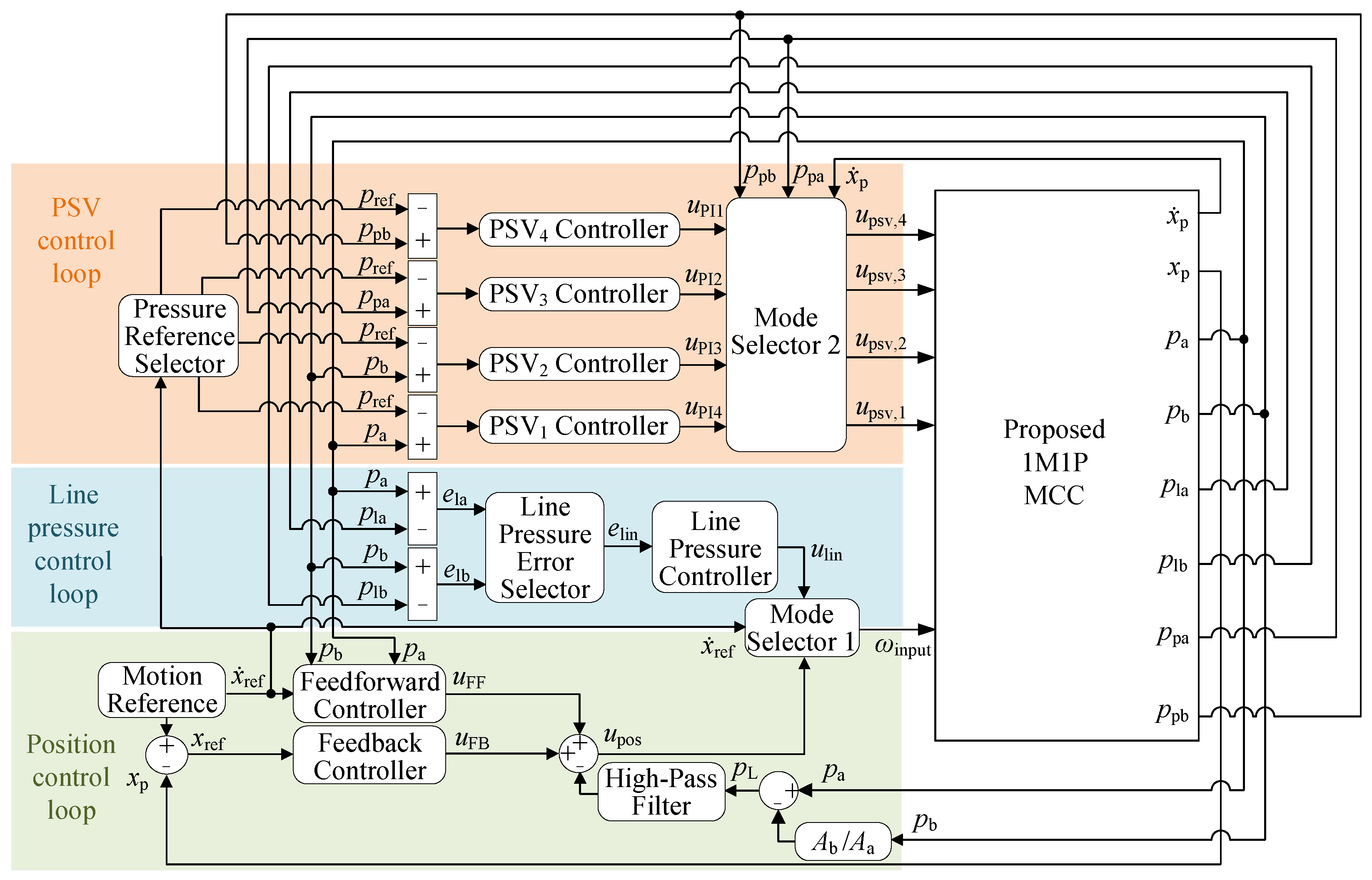
The modeling approach of four PSVs is similar to that of the POCVs, i.e., Equation (
29). The symbol
is the opening area constant for the
i-th PSV. The symbol
is the pressure differential across the
i-th PSV. The dimensionless opening for each PSV,
, is given by the control signal to the solenoid. Finally, the modeling approach for the two load-holding valves follows a similar orifice equation with the dimensionless opening defined from the pilot pressure
and the valve crack pressure.
,
,
, and
are calculated using the pressure build-up equations, as shown in Equations (
30)–(
33).
,
,
, and
are the volumes of the transmission lines. Because of
(or
), when the hose between
(or
) and
(or
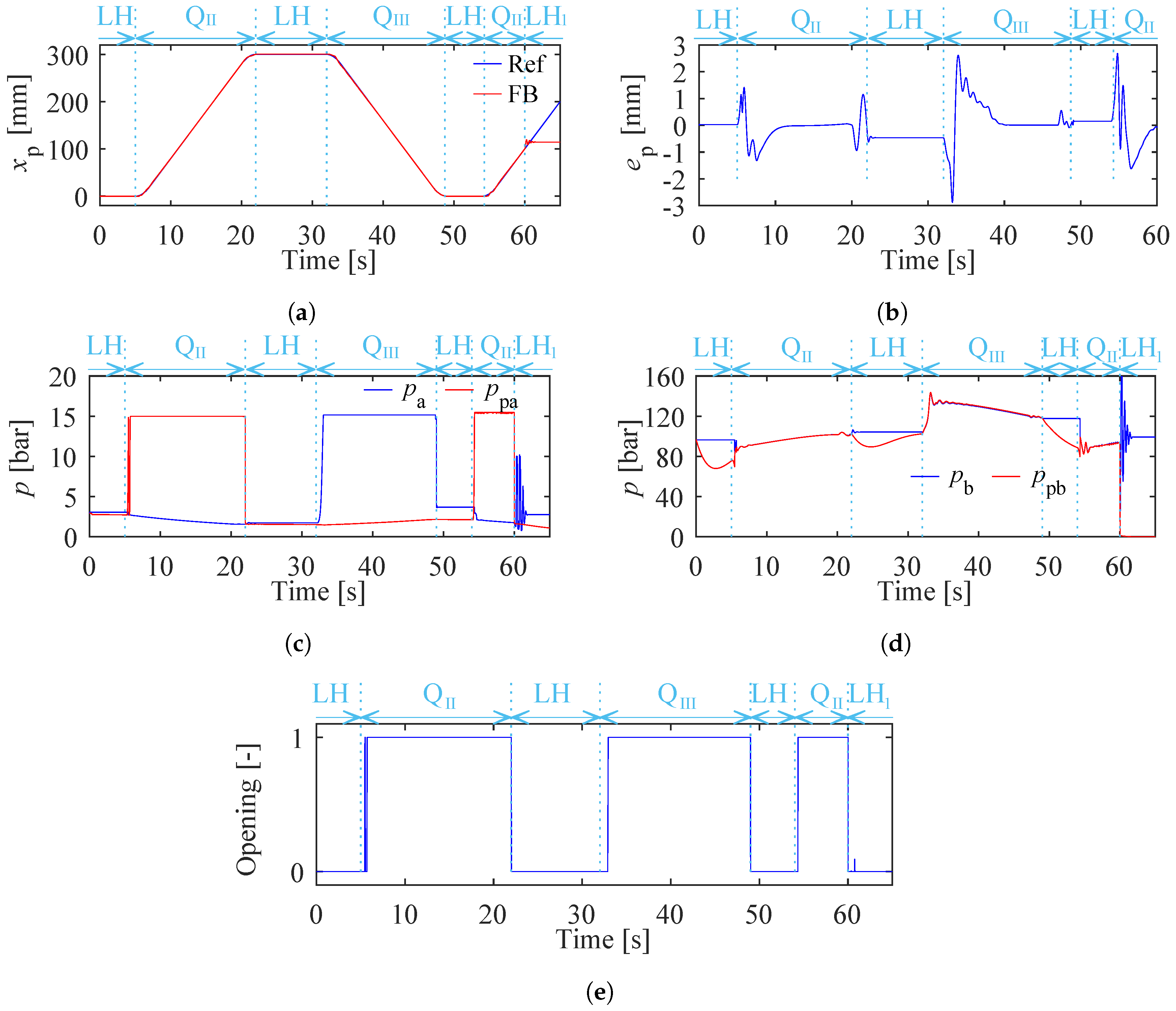
) ruptures,
(or
) becomes zero. Therefore, the hose rupture is realized by forcing
(or
) to zero at 60 s in simulations.
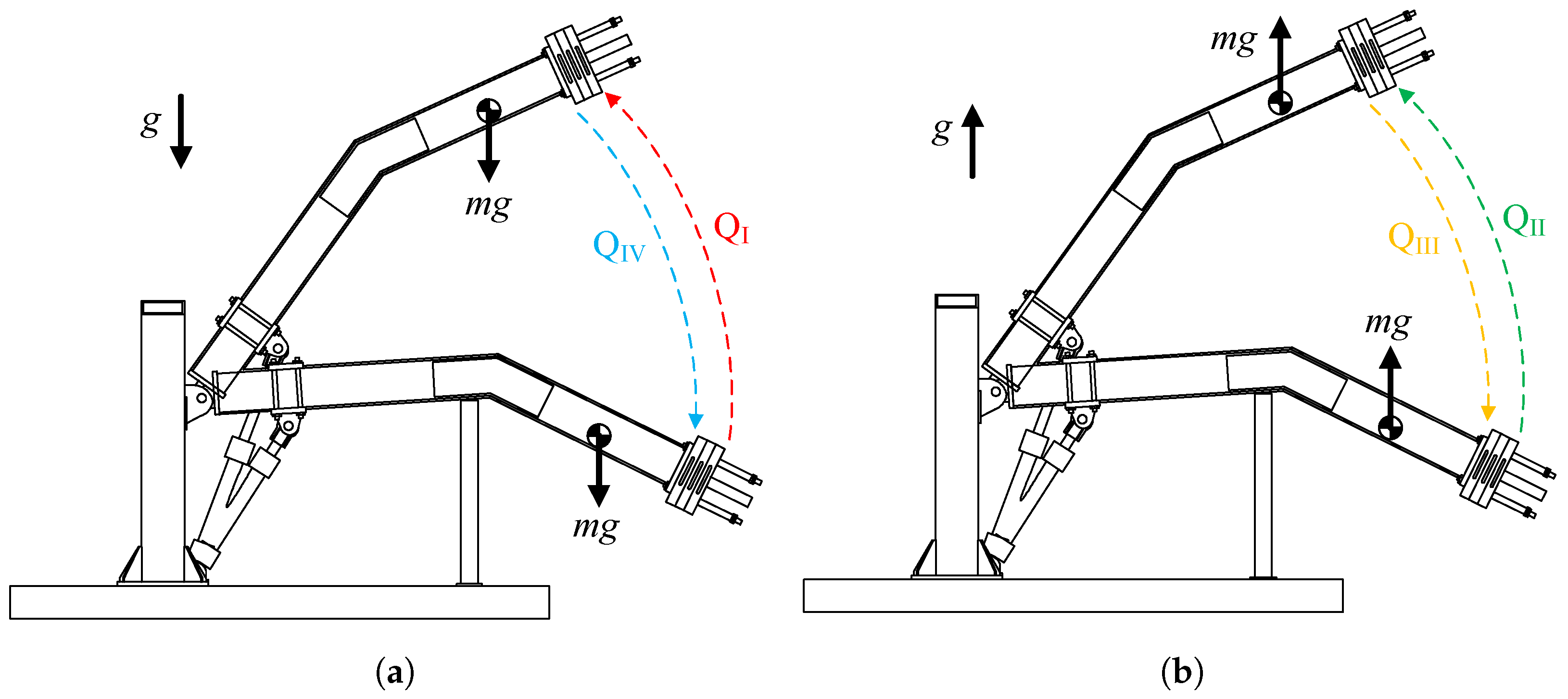
The laboratory single-boom crane investigated in a previous experimental study [
18] is used in this paper as an application to verify the proposed 1M1P MCC’s functionalities. This crane is modeled in the Simulink-Simscape. The crane model receives the hydraulic cylinder force from the hydraulic system model and provides piston position and velocity back to the hydraulic system model. The crane is shown in
Figure 6 with some of the main inertia data. The total mass of the crane boom and the payload is 300.8 kg, with the mass center located at a distance of 1.77 m from the hinge. It is important to emphasize that, within this crane system, our analysis solely incorporates the friction between the cylinder and the piston, as modeled by Equation (
16). Any additional frictional effects at the hinges have been disregarded for simplicity.
6. Discussion
The proposed 1M1P MCC can realize the system pressure control, four-quadrant operation, and passive load-holding function triggered by emergencies, such as power loss and hose rupture. Furthermore, it can be deployed in remote installation [
12], where the 1M1P MCC drive unit and the cylinder with a passive load-holding device are installed separately and connected via pipelines. Compared with the 2M2P MCC proposed in [
18], which can offer the same functionalities, 1M1P MCC has disadvantages and advantages.
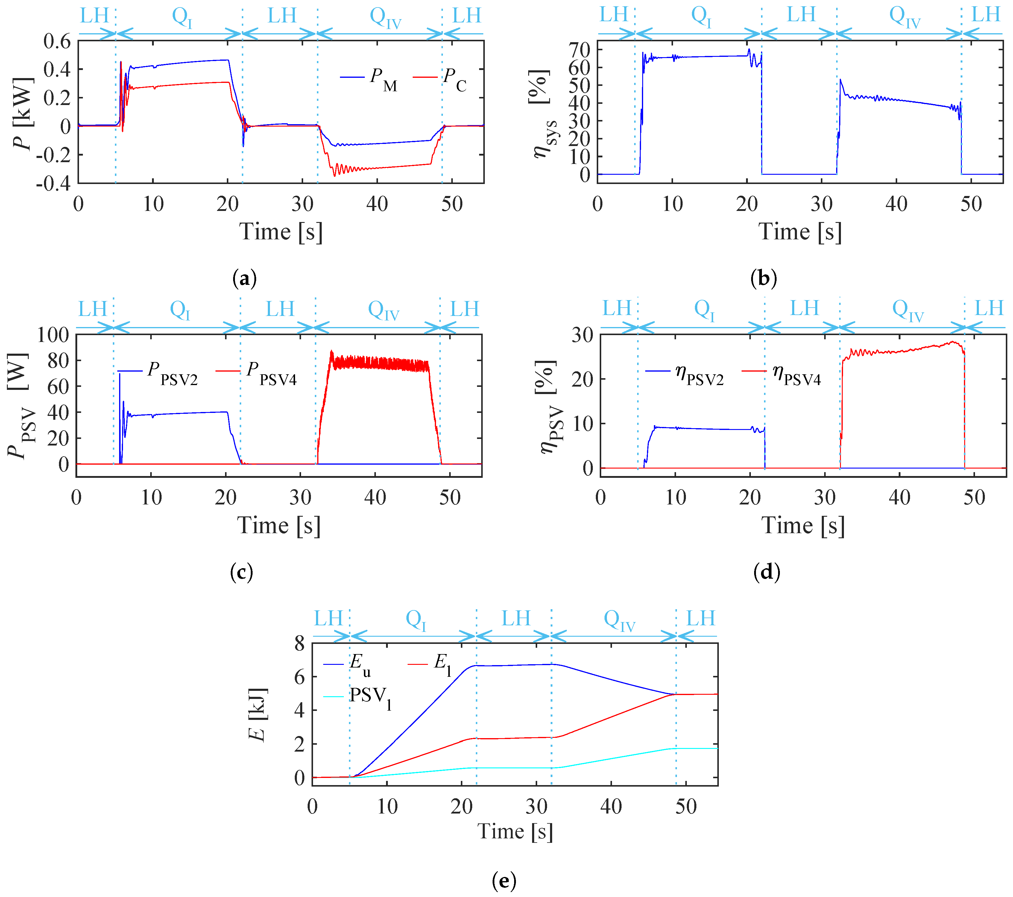
As described in
Section 5.3, the PSVs in the 1M1P MCC cause energy losses ranging from 8% to 26%, depending on the specific operational conditions. These losses are due to the throttling losses in the PSVs. It is important to note that the energy losses in PSVs remain independent of the output powers. Additionally, in scenario A, the highest working pressure is below 60 bar, considerably lower than typical industrial applications. Consequently, with increased load and output power, the proportion of PSV losses is expected to diminish significantly. In contrast, there were no throttling losses in the 2M2P MCC investigated in [
18]. This 2M2P MCC used the same load-holding circuit. Therefore, in theory, it has higher system energy efficiency than the proposed 1M1P MCC. Additionally, since no valves are required to compensate for the cylinder differential flow rate, the issue of pump mode oscillation does not arise in 2M2P MCCs.
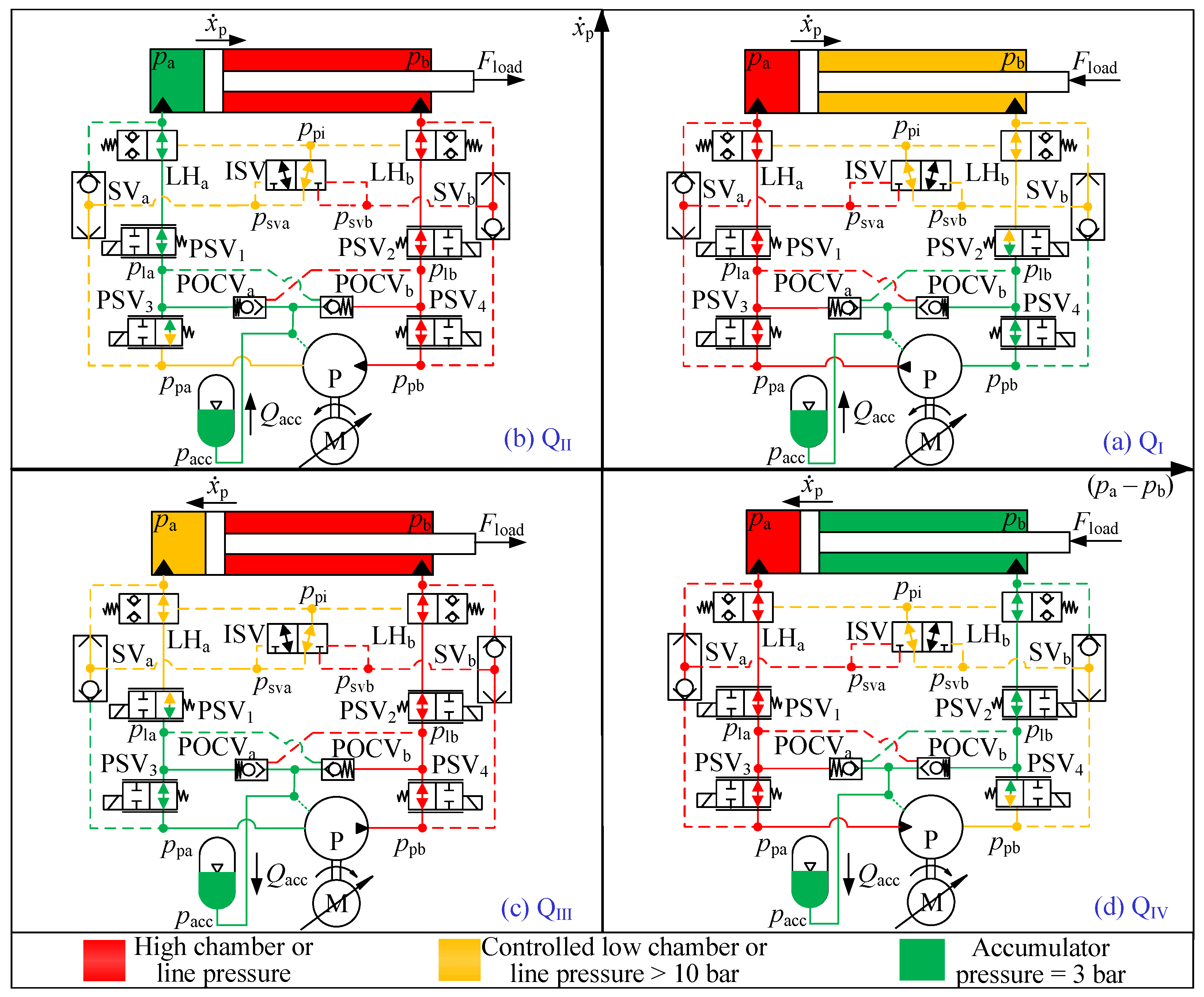
The proposed 1M1P MCC surpasses the 2M2P MCC in [
18] because of its superior suitability for four-quadrant operation. In the proposed 1M1P MCC, the electric servo motor and hydraulic pump/motor unit effectively contribute to the cylinder’s output power in
and
or engage in power regeneration in
and
. In contrast, the 2M2P MCC’s secondary electric servo motor and hydraulic pump/motor unit can only contribute to the cylinder’s output power in
or engage in power regeneration in
[
18]. Additionally, the secondary electric servo motor’s rated power in the 2M2P MCC must be greater than the main electric servo motor’s power because of the system pressure control [
18]. Consequently, when significant cylinder output power in
is required, an applicable 2M2P MCC becomes more costly and significantly larger than a 1M1P MCC. Therefore, the 2M2P MCC is more suitable for operations only in
and
.
The proposed control algorithm holds promise for application to other motor-controlled cylinders featuring a similar load-holding mechanism. However, adjustments are necessary to tailor the algorithm to accommodate varying numbers of hydraulic pumps and electric motors utilized in different setups. Moreover, while this paper introduces a novel concept in motor-controlled cylinder structures, the robustness and limitations of the control algorithm remain to be extensively explored. Further research efforts are needed in this regard.


